LT-1002_RAM-300LCD_Installation_and_Operation_Manual - Mircom
LT-1002_RAM-300LCD_Installation_and_Operation_Manual - Mircom
LT-1002_RAM-300LCD_Installation_and_Operation_Manual - Mircom

Create successful ePaper yourself
Turn your PDF publications into a flip-book with our unique Google optimized e-Paper software.
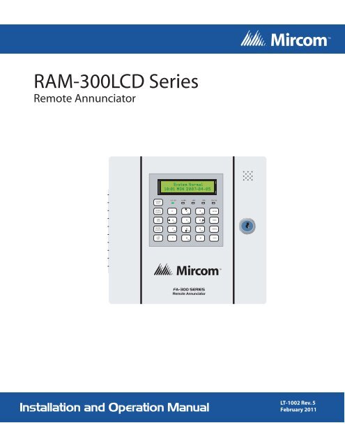
<strong>RAM</strong>-<strong>300LCD</strong> Series<br />
Remote Annunciator<br />
System Normal<br />
18:01 MON 2007-04-05<br />
SYSTEM<br />
RESET<br />
A.C. O N ALARM SUPV TRBL CPU FAIL<br />
SIG N AL<br />
SILEN CE<br />
1<br />
2<br />
ABC<br />
3<br />
DEF<br />
EN TER<br />
FIRE<br />
DRILL<br />
4<br />
5<br />
6<br />
GHI JKL MNO<br />
MEN U<br />
BUZZER<br />
SILEN CE<br />
7<br />
8<br />
9<br />
PRS TUV W XY<br />
CAN CEL<br />
LAMP<br />
TEST<br />
*<br />
0<br />
QZ<br />
#<br />
IN FO<br />
FA-300 SERIES<br />
Remote Annunciator<br />
<strong>Installation</strong> <strong>and</strong> <strong>Operation</strong> <strong>Manual</strong><br />
<strong>LT</strong>-<strong>1002</strong> Rev. 5<br />
February 2011
Table of Contents<br />
Table of Contents<br />
1.0 Introduction 7<br />
1.1 Contact Us ...................................................................................................................... 8<br />
1.1.1 General Inquiries ............................................................................................................ 8<br />
1.1.2 Customer Service ........................................................................................................... 8<br />
1.1.3 Technical Support ........................................................................................................... 8<br />
1.1.4 Website ........................................................................................................................... 8<br />
2.0 Mechanical <strong>Installation</strong> 9<br />
3.0 Functional Setup 10<br />
3.1 Jumpers .......................................................................................................................... 10<br />
3.2 Potentiometer ................................................................................................................. 10<br />
3.3 DIP Switches .................................................................................................................. 11<br />
4.0 Wiring 12<br />
5.0 Specifications & Features 14<br />
5.1 Enclosure ........................................................................................................................ 14<br />
5.2 Electrical Specifications .................................................................................................. 14<br />
5.3 Current Drain for Battery Calculations ............................................................................ 14<br />
5.4 Environmental Specifications ......................................................................................... 14<br />
6.0 Operating Instructions 15<br />
7.0 Warranty <strong>and</strong> Warning Information 16<br />
7.1 Warning Please Read Carefully .................................................................................... 16<br />
7.2 Note to Installers ............................................................................................................. 16<br />
7.3 System Failures .............................................................................................................. 16<br />
7.3.1 Inadequate <strong>Installation</strong> ................................................................................................... 16<br />
7.3.2 Power Failure ................................................................................................................. 16<br />
7.3.3 Failure of Replaceable Batteries .................................................................................... 16<br />
7.3.4 Compromise of Radio Frequency (Wireless) Devices .................................................... 17<br />
7.3.5 System Users ................................................................................................................. 17<br />
7.3.6 Automatic Alarm Initiating Devices ................................................................................. 17<br />
7.3.7 Software ......................................................................................................................... 17<br />
7.3.8 Alarm Notification Appliances ......................................................................................... 17<br />
7.3.9 Telephone Lines ............................................................................................................. 18<br />
7.3.10 Insufficient Time ............................................................................................................. 18<br />
3
Table of Contents<br />
7.3.11 Component Failure ......................................................................................................... 18<br />
7.3.12 Inadequate Testing ........................................................................................................ 18<br />
7.3.13 Security <strong>and</strong> Insurance .................................................................................................. 18<br />
7.4 Limited Warranty ............................................................................................................ 18<br />
7.4.1 International Warranty .................................................................................................... 18<br />
7.4.2 Conditions to Void Warranty .......................................................................................... 19<br />
7.5 Warranty Procedure ....................................................................................................... 19<br />
7.6 Disclaimer of Warranties ................................................................................................ 19<br />
7.7 Out of Warranty Repairs ................................................................................................ 19<br />
4
List of Figures <strong>and</strong> Tables<br />
List of Figures <strong>and</strong> Tables<br />
Figure 1 Remote Annunciator Dimensions ................................................................................... 7<br />
Figure 2 Mechanical <strong>Installation</strong> ................................................................................................... 9<br />
Figure 3 Annunciator Component Descriptions ............................................................................ 10<br />
Table 1 Jumpers .......................................................................................................................... 10<br />
Table 2 <strong>RAM</strong>-<strong>300LCD</strong> Address DIP Switch Setup ...................................................................... 11<br />
Table 3 DIP switch SW31 settings ............................................................................................... 11<br />
Table 4 Maximum Wiring Run to Last Annunciator ..................................................................... 12<br />
Figure 4 <strong>RAM</strong>-<strong>300LCD</strong> Wiring ...................................................................................................... 13<br />
5
6<br />
List of Figures <strong>and</strong> Tables
Introduction<br />
1.0 Introduction<br />
The <strong>RAM</strong>-<strong>300LCD</strong> is a remote annunciator used for the FA-300 Series <strong>and</strong> FX-350/351 Series<br />
Fire Alarm Panels. It provides remote access to the fire alarm panel.<br />
i<br />
Note:<br />
Configuration of the FA-300 Series <strong>and</strong> FX-350/351 Series fire alarm panels from<br />
this remote annunciator is not allowed.<br />
The <strong>RAM</strong>-<strong>300LCD</strong> has an LCD display, common feature LEDs <strong>and</strong> pushbuttons, as well as an<br />
alpha numeric keypad for the LCD.<br />
The <strong>RAM</strong>-<strong>300LCD</strong> comes complete with an enclosure <strong>and</strong> can be surface mounted.<br />
7.7"<br />
SYSTEM NORMAL<br />
18:01 MON 2011-02-07<br />
SYSTEM<br />
RESET<br />
A.C. ON ALARM SUPV TRBL CPU FAIL<br />
SIGNAL<br />
SILENCE<br />
1<br />
2<br />
ABC<br />
3<br />
DEF<br />
ENTER<br />
7.2"<br />
FIRE<br />
DRILL<br />
4<br />
5<br />
6<br />
GHI JKL MNO<br />
MENU<br />
BUZZER<br />
SILENCE<br />
7<br />
8<br />
9<br />
PRS TUV WXY<br />
CANCEL<br />
LAMP<br />
TEST<br />
*<br />
0<br />
QZ<br />
#<br />
INFO<br />
FA-300 SERIES<br />
Remote Annunciator<br />
1.25"<br />
Figure 1<br />
Remote Annunciator Dimensions<br />
Each <strong>RAM</strong>-<strong>300LCD</strong> has its own address. Addresses available are 1 to <strong>and</strong> including 7. The<br />
buttons on the left side may be individually disabled if required, by setting DIP Switch SW31,<br />
see Functional Setup section following.<br />
This annunciator may be selected to operate as an ancillary device using DIP Switch SW31-6<br />
to disable all buttons except, Lamp Test, Buzzer Silence, Info <strong>and</strong> Arrow Buttons.<br />
i<br />
Note:<br />
This ancillary device option, if selected takes priority over any other selections<br />
made on DIP Switch SW31.<br />
7
1.1 Contact Us<br />
For General Inquiries, Customer Service <strong>and</strong> Technical Support you can contact us Monday to<br />
Friday 8:00 A.M. to 5:00 P.M. E.S.T.<br />
1.1.1 General Inquiries<br />
Toll Free<br />
1-888-660-4655 (North America Only)<br />
Local 905-660-4655<br />
Email<br />
mail@mircom.com<br />
1.1.2 Customer Service<br />
Toll Free<br />
1-888-MIRCOM5 (North America Only)<br />
Local 905-695-3535<br />
Toll Free Fax<br />
1-888-660-4113 (North America Only)<br />
Local Fax 905-660-4113<br />
Email<br />
salessupport@mircom.com<br />
1.1.3 Technical Support<br />
Toll Free<br />
1-888-MIRCOM5 (North America Only)<br />
888-647-2665<br />
International 905-647-2665<br />
Email<br />
techsupport@mircom.com<br />
1.1.4 Website<br />
www.mircom.com<br />
8
Mechanical <strong>Installation</strong><br />
2.0 Mechanical <strong>Installation</strong><br />
To mount the <strong>RAM</strong>-<strong>300LCD</strong> open the front door, remove the dead front plate <strong>and</strong> mount the<br />
backbox to the wall using the four screws provided. This enclosure may also be mounted to a<br />
4” square electrical box. There are two conduit areas provided at the bottom center of the<br />
enclosure. With the dead front plate removed, you may do the functional setup <strong>and</strong> wiring<br />
before replacing the dead front, see following sections.<br />
7.5"<br />
6.0"<br />
7.0<br />
FOUR<br />
MOUNTING<br />
HOLES<br />
5.9"<br />
1.22"<br />
Figure 2<br />
Mechanical <strong>Installation</strong><br />
9
Functional Setup<br />
3.0 Functional Setup<br />
LCD CONTRAST<br />
ADJUSTMENT<br />
JW1, JW2, JW3 ARE<br />
FOR FACTORY USE<br />
LEAVE JUMPERS<br />
JW2 AND JW3 IN<br />
PLACE.<br />
VR1<br />
JW1<br />
JW2<br />
JW3<br />
P2<br />
SYSTEM<br />
RESET<br />
SIGNAL<br />
SILENCE<br />
SYSTEM NORMAL<br />
18:01 MON 2011-02-07<br />
A.C. ON ALARM SUPV TRBL CPU FAIL<br />
1<br />
2<br />
ABC<br />
3<br />
DEF<br />
ENTER<br />
FIRE<br />
DRILL<br />
4<br />
5<br />
6<br />
GHI JKL MNO<br />
MENU<br />
THESE PINS ARE<br />
FOR FACTORY USE<br />
ONLY<br />
24V IN/OUT<br />
- +<br />
CUT JUMPER JW8 TO<br />
MAKE <strong>RAM</strong>-<strong>300LCD</strong> AN<br />
ANCILLARY DEVICE.<br />
JW8<br />
BUZZER<br />
SILENCE<br />
ON<br />
LAMP<br />
TEST<br />
1 2 3 4 5 6 7 8<br />
SW31<br />
Figure 3<br />
7<br />
8<br />
9<br />
PRS TUV WXY<br />
*<br />
0<br />
QZ<br />
SW31 DIP Switch<br />
for various<br />
system functions<br />
#<br />
CANCEL<br />
INFO<br />
SW30<br />
ON<br />
1 2 3 4<br />
RS-485 IN/OUT<br />
+ - S<br />
SW30 DIP Switch for annunciator<br />
address setting. Valid addresses<br />
1 to 7.<br />
Annunciator Component Descriptions<br />
P1<br />
THIS<br />
CONNECTOR IS<br />
FOR FACTORY<br />
USE ONLY<br />
Place the 120 ohm<br />
EOL resistor between<br />
+ <strong>and</strong> - terminals of<br />
the RS-485 on the<br />
last annunciator<br />
only.<br />
3.1 Jumpers<br />
Table 1 Jumpers<br />
Jumper<br />
JW1<br />
JW2<br />
JW3<br />
JW8<br />
Jumper Function<br />
FACTORY USE ONLY (JUMPER OFF)<br />
FACTORY USE ONLY (JUMPER INSTALLED)<br />
FACTORY USE ONLY (JUMPER INSTALLED)<br />
CUT jumper to set the <strong>RAM</strong>-<strong>300LCD</strong> as an ancillary device. Use NP-2051 blank labels<br />
to cover the System Reset, Signal Silence, Fire Drill, Enter, Menu <strong>and</strong> Cancel buttons<br />
for the Ancillary Device Feature. Only Buzzer Silence, Lamp Test <strong>and</strong> Info are used.<br />
3.2 Potentiometer<br />
VR1 is a potentiometer used for LCD contrast adjustment <strong>and</strong> is located in the top left corner<br />
of the <strong>RAM</strong>-<strong>300LCD</strong> board.<br />
10
Functional Setup<br />
3.3 DIP Switches<br />
There are two DIP switches to be set. SW30 is found at the bottom right corner of the board<br />
<strong>and</strong> is used to select the annunciator address. Valid addresses are 1 to 6 inclusive for FA-300<br />
Series, 1 to 7 for FX-350/351. Set address as follows:<br />
Table 2 <strong>RAM</strong>-<strong>300LCD</strong> Address DIP Switch Setup<br />
Address SW30-1 SW30-2 SW30-3<br />
1 ON OFF OFF<br />
2 OFF ON OFF<br />
3 ON ON OFF<br />
4 OFF OFF ON<br />
5 ON OFF ON<br />
6 OFF ON ON<br />
7 (FX-350/351) ON ON ON<br />
i<br />
Note:<br />
SW30-4 DIP switch is not used.<br />
i<br />
Note:<br />
For the FX-350/351 Series Fire Alarm Panels, if the number of annunciators<br />
programmed is 5, then the first five addresses (1 to 5 inclusive) must be assigned<br />
to the <strong>RAM</strong>-<strong>300LCD</strong> annunciators.<br />
DIP switch SW31 is found at the bottom left h<strong>and</strong> corner <strong>and</strong> is used to select a number of<br />
features. DIP switch SW31 is set as follows:<br />
Table 3 DIP switch SW31 settings<br />
DIP Switch SW31 Position Function<br />
1 ON Disable System Reset Button<br />
1 OFF Enable System Reset Button<br />
2 ON Disable Signal Silence Button<br />
2 OFF Enable Signal Silence Button<br />
3 ON Disable Fire Drill Button<br />
3 OFF Enable Fire Drill Button<br />
4 ON Disable Lamp Test Button<br />
4 OFF Enable Lamp Test Button<br />
5 ON Disable Buzzer Silence Button<br />
5 OFF Enable Buzzer Silence Button<br />
6 NOT USED<br />
7 ON 16 bit checksum (for FX-350/351 panels)<br />
7 OFF 8 bit checksum (for FA-300 Series panels)<br />
8 NOT USED<br />
11
Wiring<br />
4.0 Wiring<br />
To wire the <strong>RAM</strong>-<strong>300LCD</strong>, you must first remove the dead front plate. Wire from the last <strong>RAM</strong>-<br />
<strong>300LCD</strong> to the next <strong>RAM</strong>-<strong>300LCD</strong> <strong>and</strong> so on; then from the first <strong>RAM</strong>-<strong>300LCD</strong> to the Fire<br />
Alarm Panel. There are only two connections to be made, one for power <strong>and</strong> the RS-485 loop.<br />
Replace the dead front plate once all functional setup <strong>and</strong> wiring is complete.<br />
The RS-485 Wiring to the <strong>RAM</strong>-<strong>300LCD</strong> is recommended to be Twisted Shielded Pair. The<br />
wire gauge may be<br />
• 22 AWG up to 2000 ft.<br />
• 20 AWG up to 4000 ft.<br />
The 24V DC field wiring needs to be of an appropriate gauge for the number of annunciators<br />
<strong>and</strong> the total wiring run length. See Current Drain for Battery Calculations on page 14 <strong>and</strong><br />
calculate the Maximum current for all annunciators summed together.<br />
i<br />
Note:<br />
All circuits are power limited <strong>and</strong> must use type FPL, FPLR or FPLP Power<br />
Limited Cable.<br />
!<br />
Attention: Accidentally connecting any of the 24V DC wires to the RS-485 wiring will<br />
result in damage to the Annunciator <strong>and</strong>/or to the Fire Alarm Control Panel to<br />
which it is connected.<br />
Table 4 Maximum Wiring Run to Last Annunciator<br />
Max for all<br />
Annunciators<br />
18AWG 16AWG 14AWG 12AWG<br />
Max Loop<br />
Resistance<br />
Amperes ft m ft m ft m ft m Ohms<br />
0.12 1180 360 1850 567 3000 915 4250 1296 15<br />
0.30 470 143 750 229 1200 366 1900 579 6<br />
0.60 235 71 375 114 600 183 850 259 3<br />
0.90 156 47 250 76 400 122 570 174 2<br />
1.20 118 36 185 56 300 91 425 129 1.5<br />
1.50 94 29 150 46 240 73 343 105 1.2<br />
1.70 78 24 125 38 200 61 285 87 1.0<br />
12
Wiring<br />
The <strong>RAM</strong>-<strong>300LCD</strong> is wired as shown below. Additional <strong>RAM</strong>-<strong>300LCD</strong>s are wired in the same<br />
manner, make sure ONLY the last <strong>RAM</strong>-<strong>300LCD</strong> has the 120 ohm E.O.L. resistor connected<br />
to the RS-485 positive <strong>and</strong> negative terminals.<br />
MAKE SURE<br />
THERE IS A<br />
120 OHM E.O.L.<br />
RESISTOR<br />
BETWEEN + AND -<br />
ON THE LAST<br />
ANNUNCIATOR<br />
ONLY<br />
- 24V IN /OUT + RS-485 IN/OUT<br />
S - +<br />
<strong>RAM</strong>-<strong>300LCD</strong><br />
ADDRESS 2<br />
RS-485 IN/OUT<br />
- 24V IN /OUT + S - +<br />
<strong>RAM</strong>-<strong>300LCD</strong><br />
ADDRESS 1<br />
RS-485 +<br />
+ -<br />
-<br />
S<br />
FA-300 FIRE<br />
ALARM PANEL<br />
AUX<br />
SUPPLY<br />
Figure 4<br />
<strong>RAM</strong>-<strong>300LCD</strong> Wiring<br />
13
Specifications & Features<br />
5.0 Specifications & Features<br />
5.1 Enclosure<br />
Enclosure may be mounted on a 4” square electrical box or on a wall.<br />
5.2 Electrical Specifications<br />
• 24 VDC nominal voltage<br />
• LCD Display, Pushbutton Controls <strong>and</strong> LED indicators.<br />
• Local Buzzer, Indicators (AC-On, Alarm, Supervisory, Trouble <strong>and</strong> CPU Fail), <strong>and</strong><br />
Controls (System Reset, Signal Silence, Fire Drill, Buzzer Silence <strong>and</strong> Lamp Test,).<br />
• Annunciation of up to 16 Points.<br />
• Not Exp<strong>and</strong>able.<br />
• St<strong>and</strong>by 16 mA Max., Alarm 40mA Max. All LEDs illuminated 40 mA Max.<br />
5.3 Current Drain for Battery Calculations<br />
The maximum normal current drain will be during Lamp Test when all lamps are illuminated on<br />
one chassis at a time. Thus the currents are:<br />
• Normal St<strong>and</strong>by =16 mA<br />
• Maximum=40 mA<br />
The Normal St<strong>and</strong>by Current is used for battery size calculations (see the FA-300 Series or<br />
FX-350/351 Series Fire Alarm Control Panel manual for battery calculations) <strong>and</strong> includes the<br />
current drain for the Trouble Buzzer, Trouble LED, <strong>and</strong> one Alarm LED. The Maximum<br />
Current is used to calculate the wire size (see Wiring section above).<br />
5.4 Environmental Specifications<br />
This annunciator is intended for indoor use only.<br />
14
Operating Instructions<br />
6.0 Operating Instructions<br />
Normal<br />
Alarm<br />
Silencing of<br />
Alarm<br />
All indicators are normally OFF except for the green A.C. ON light which illuminates steadily.<br />
Operate Alarm Initiating Devices to activate Indicating Appliances. Signals will sound,<br />
common alarm will illuminate red.<br />
Press Signal Silence button momentarily to silence all audible signals.<br />
i<br />
Note:<br />
The signal silencing function may be inhibited for up to one minute. The Signal<br />
silence button will not operate until the inhibit period has expired.<br />
Waterflow<br />
Supervisory<br />
System<br />
Reset<br />
Trouble<br />
Fire Drill<br />
Lamp Test<br />
CPU Fail LED<br />
Menu Button<br />
Enter, Cancel<br />
<strong>and</strong> Info<br />
Buttons<br />
Keypad<br />
Indicating appliances <strong>and</strong> other output circuits that are activated in response to an alarm<br />
initiated by a designated Waterflow Zone cannot be silenced (manual or automatic).<br />
Activation of any initiating devices for supervisory will sound the buzzer continuously. The<br />
Common supervisory indicator will illuminate amber (steady). The Common Supervisory<br />
indicator remains "ON" when the buzzer is silenced.<br />
Press the Reset button momentarily to restore normal operation. All alarm indicators will<br />
extinguish & all latched functions are restored.<br />
Any system trouble will sound the buzzer intermittently <strong>and</strong> common Trouble indicator will<br />
flash amber until the fault is corrected. Specific types of trouble will be indicated by the LCD<br />
display by pressing the INFO button. Call for service.<br />
Press the Fire Drill button momentarily to sound all audible signals without initiating an<br />
alarm. Press the button again for normal system operation. Note: Auxiliary relays will not<br />
operate when Fire Drill is operated.<br />
Press the Lamp Test button momentarily to test all indicators. All indicators should be lit <strong>and</strong><br />
buzzer will sound. Holding down this button will display the firmware version.<br />
Will illuminate amber for an onboard CPU error.<br />
Press the Menu button to access the associated FA-300 Series Fire Alarm Panel. The Menu<br />
button operates as it does on the main FA-300 Series Fire Alarm Panel, refer to the fire<br />
alarm manual for further explanation. Use the keypad arrow keys (2, 4, 6 <strong>and</strong> 8) to scroll<br />
through the menu. Configuration of the fire alarm panel cannot be accessed from the <strong>RAM</strong>-<br />
<strong>300LCD</strong>. The Menu button does not operate for the FX-350/351 Series Fire Alarm Panels.<br />
The Enter <strong>and</strong> Cancel buttons are used to input <strong>and</strong> erase some data for the fire alarm panel<br />
<strong>and</strong> the Info button is used to view the fire alarm panel logs. The Enter <strong>and</strong> Cancel buttons<br />
do not operate for the FX-350/351 Series Fire Alarm Panels.<br />
The numbered keys <strong>and</strong>/or letter keys function as they do at the FA-300 Series Fire Alarm<br />
Panel, refer to the fire alarm manual for further explanation. The keypad does not operate<br />
for the FX-350/351 Series Fire Alarm Panels.<br />
15
Warranty <strong>and</strong> Warning Information<br />
7.0 Warranty <strong>and</strong> Warning Information<br />
7.1 Warning Please Read Carefully<br />
i<br />
Note to End UsersThis equipment is subject to terms <strong>and</strong> conditions of sale as follows:<br />
7.2 Note to Installers<br />
This warning contains vital information. As the only individual in contact with system users, it is<br />
your responsibility to bring each item in this warning to the attention of the users of this<br />
system. Failure to properly inform system end-users of the circumstances in which the system<br />
might fail may result in over-reliance upon the system. As a result, it is imperative that you<br />
properly inform each customer for whom you install the system of the possible forms of failure.<br />
7.3 System Failures<br />
This system has been carefully designed to be as effective as possible. There are<br />
circumstances, such as fire or other types of emergencies where it may not provide protection.<br />
Alarm systems of any type may be compromised deliberately or may fail to operate as<br />
expected for a variety of reasons. Some reasons for system failure include:<br />
7.3.1 Inadequate <strong>Installation</strong><br />
A Fire Alarm system must be installed in accordance with all the applicable codes <strong>and</strong><br />
st<strong>and</strong>ards in order to provide adequate protection. An inspection <strong>and</strong> approval of the initial<br />
installation, or, after any changes to the system, must be conducted by the Local Authority<br />
Having Jurisdiction. Such inspections ensure installation has been carried out properly.<br />
7.3.2 Power Failure<br />
Control units, smoke detectors <strong>and</strong> many other connected devices require an adequate power<br />
supply for proper operation. If the system or any device connected to the system operates<br />
from batteries, it is possible for the batteries to fail. Even if the batteries have not failed, they<br />
must be fully charged, in good condition <strong>and</strong> installed correctly. If a device operates only by<br />
AC power, any interruption, however brief, will render that device inoperative while it does not<br />
have power. Power interruptions of any length are often accompanied by voltage fluctuations<br />
which may damage electronic equipment such as a fire alarm system. After a power<br />
interruption has occurred, immediately conduct a complete system test to ensure that the<br />
system operates as intended.<br />
7.3.3 Failure of Replaceable Batteries<br />
Systems with wireless transmitters have been designed to provide several years of battery life<br />
under normal conditions. The expected battery life is a function of the device environment,<br />
usage <strong>and</strong> type. Ambient conditions such as high humidity, high or low temperatures, or large<br />
temperature fluctuations may reduce the expected battery life. While each transmitting device<br />
has a low battery monitor which identifies when the batteries need to be replaced, this monitor<br />
16
Warranty <strong>and</strong> Warning Information<br />
may fail to operate as expected. Regular testing <strong>and</strong> maintenance will keep the system in<br />
good operating condition.<br />
7.3.4 Compromise of Radio Frequency (Wireless) Devices<br />
Signals may not reach the receiver under all circumstances which could include metal objects<br />
placed on or near the radio path or deliberate jamming or other inadvertent radio signal<br />
interference.<br />
7.3.5 System Users<br />
A user may not be able to operate a panic or emergency switch possibly due to permanent or<br />
temporary physical disability, inability to reach the device in time, or unfamiliarity with the<br />
correct operation. It is important that all system users be trained in the correct operation of the<br />
alarm system <strong>and</strong> that they know how to respond when the system indicates an alarm.<br />
7.3.6 Automatic Alarm Initiating Devices<br />
Smoke detectors, heat detectors <strong>and</strong> other alarm initiating devices that are a part of this<br />
system may not properly detect a fire condition or signal the control panel to alert occupants of<br />
a fire condition for a number of reasons, such as: the smoke detectors or heat detector may<br />
have been improperly installed or positioned; smoke or heat may not be able to reach the<br />
alarm initiating device, such as when the fire is in a chimney, walls or roofs, or on the other<br />
side of closed doors; <strong>and</strong>, smoke <strong>and</strong> heat detectors may not detect smoke or heat from fires<br />
on another level of the residence or building.<br />
7.3.7 Software<br />
Most <strong>Mircom</strong> products contain software. With respect to those products, <strong>Mircom</strong> does not<br />
warranty that the operation of the software will be uninterrupted or error-free or that the<br />
software will meet any other st<strong>and</strong>ard of performance, or that the functions or performance of<br />
the software will meet the user’s requirements. <strong>Mircom</strong> shall not be liable for any delays,<br />
breakdowns, interruptions, loss, destruction, alteration or other problems in the use of a<br />
product arising our of, or caused by, the software.<br />
Every fire is different in the amount <strong>and</strong> rate at which smoke <strong>and</strong> heat are generated. Smoke<br />
detectors cannot sense all types of fires equally well. Smoke detectors may not provide timely<br />
warning of fires caused by carelessness or safety hazards such as smoking in bed, violent<br />
explosions, escaping gas, improper storage of flammable materials, overloaded electrical<br />
circuits, children playing with matches or arson.<br />
Even if the smoke detector or heat detector operates as intended, there may be circumstances<br />
when there is insufficient warning to allow all occupants to escape in time to avoid injury or<br />
death.<br />
7.3.8 Alarm Notification Appliances<br />
Alarm Notification Appliances such as sirens, bells, horns, or strobes may not warn people or<br />
waken someone sleeping if there is an intervening wall or door. If notification appliances are<br />
located on a different level of the residence or premise, then it is less likely that the occupants<br />
will be alerted or awakened. Audible notification appliances may be interfered with by other<br />
noise sources such as stereos, radios, televisions, air conditioners or other appliances, or<br />
passing traffic. Audible notification appliances, however loud, may not be heard by a hearingimpaired<br />
person.<br />
17
Warranty <strong>and</strong> Warning Information<br />
7.3.9 Telephone Lines<br />
If telephone lines are used to transmit alarms, they may be out of service or busy for certain<br />
periods of time. Also the telephone lines may be compromised by such things as criminal<br />
tampering, local construction, storms or earthquakes.<br />
7.3.10 Insufficient Time<br />
There may be circumstances when the system will operate as intended, yet the occupants will<br />
not be protected from the emergency due to their inability to respond to the warnings in a<br />
timely manner. If the system is monitored, the response may not occur in time enough to<br />
protect the occupants or their belongings.<br />
7.3.11 Component Failure<br />
Although every effort has been made to make this system as reliable as possible, the system<br />
may fail to function as intended due to the failure of a component.<br />
7.3.12 Inadequate Testing<br />
Most problems that would prevent an alarm system from operating as intended can be<br />
discovered by regular testing <strong>and</strong> maintenance. The complete system should be tested as<br />
required by national st<strong>and</strong>ards <strong>and</strong> the Local Authority Having Jurisdiction <strong>and</strong> immediately<br />
after a fire, storm, earthquake, accident, or any kind of construction activity inside or outside<br />
the premises. The testing should include all sensing devices, keypads, consoles, alarm<br />
indicating devices <strong>and</strong> any other operational devices that are part of the system.<br />
7.3.13 Security <strong>and</strong> Insurance<br />
Regardless of its capabilities, an alarm system is not a substitute for property or life insurance.<br />
An alarm system also is not a substitute for property owners, renters, or other occupants to act<br />
prudently to prevent or minimize the harmful effects of an emergency situation.<br />
IMPORTANT NOTE: End-users of the system must take care to ensure that the system,<br />
batteries, telephone lines, etc. are tested <strong>and</strong> examined on a regular basis to ensure the<br />
minimization of system failure.<br />
7.4 Limited Warranty<br />
<strong>Mircom</strong> Technologies Ltd. together with its subsidiaries <strong>and</strong> affiliates (collectively, the “<strong>Mircom</strong><br />
Group of Companies”) warrants the original purchaser that for a period of three years from the<br />
date of shipment, the product shall be free of defects in materials <strong>and</strong> workmanship under<br />
normal use. During the warranty period, <strong>Mircom</strong> shall, at its option, repair or replace any<br />
defective product upon return of the product to its factory, at no charge for labor <strong>and</strong> materials.<br />
Any replacement <strong>and</strong>/or repaired parts are warranted for the remainder of the original warranty<br />
or ninety (90) days, whichever is longer. The original owner must promptly notify <strong>Mircom</strong> in<br />
writing that there is defect in material or workmanship, such written notice to be received in all<br />
events prior to expiration of the warranty period.<br />
7.4.1 International Warranty<br />
The warranty for international customers is the same as for any customer within Canada <strong>and</strong><br />
the United States, with the exception that <strong>Mircom</strong> shall not be responsible for any customs<br />
fees, taxes, or VAT that may be due.<br />
18
Warranty <strong>and</strong> Warning Information<br />
7.4.2 Conditions to Void Warranty<br />
This warranty applies only to defects in parts <strong>and</strong> workmanship relating to normal use. It does<br />
not cover:<br />
• damage incurred in shipping or h<strong>and</strong>ling;<br />
• damage caused by disaster such as fire, flood, wind, earthquake or lightning;<br />
• damage due to causes beyond the control of <strong>Mircom</strong> such as excessive voltage,<br />
mechanical shock or water damage;<br />
• damage caused by unauthorized attachment, alterations, modifications or foreign<br />
objects;<br />
• damage caused by peripherals (unless such peripherals were supplied by <strong>Mircom</strong>);<br />
• defects caused by failure to provide a suitable installation environment for the products;<br />
• damage caused by use of the products for purposes other than those for which it was<br />
designed;<br />
• damage from improper maintenance;<br />
• damage arising out of any other abuse, mish<strong>and</strong>ling or improper application of the<br />
products.<br />
7.5 Warranty Procedure<br />
To obtain service under this warranty, please return the item(s) in question to the point of<br />
purchase. All authorized distributors <strong>and</strong> dealers have a warranty program. Anyone returning<br />
goods to <strong>Mircom</strong> must first obtain an authorization number. <strong>Mircom</strong> will not accept any<br />
shipment whatsoever for which prior authorization has not been obtained. NOTE: Unless<br />
specific pre-authorization in writing is obtained from <strong>Mircom</strong> management, no credits will be<br />
issued for custom fabricated products or parts or for complete fire alarm system. <strong>Mircom</strong> will at<br />
its sole option, repair or replace parts under warranty. Advance replacements for such items<br />
must be purchased.<br />
Note: <strong>Mircom</strong>’s liability for failure to repair the product under this warranty after a reasonable<br />
number of attempts will be limited to a replacement of the product, as the exclusive remedy for<br />
breach of warranty.<br />
7.6 Disclaimer of Warranties<br />
This warranty contains the entire warranty <strong>and</strong> shall be in lieu of any <strong>and</strong> all other warranties,<br />
whether expressed or implied (including all implied warranties of merchantability or fitness for<br />
a particular purpose) And of all other obligations or liabilities on the part of <strong>Mircom</strong> neither<br />
assumes nor authorizes any other person purporting to act on its behalf to modify or to change<br />
this warranty, nor to assume for it any other warranty or liability concerning this product.<br />
This disclaimer of warranties <strong>and</strong> limited warranty are governed by the laws of the province of<br />
Ontario, Canada.<br />
7.7 Out of Warranty Repairs<br />
<strong>Mircom</strong> will at its option repair or replace out-of-warranty products which are returned to its<br />
factory according to the following conditions. Anyone returning goods to <strong>Mircom</strong> must first<br />
19
Warranty <strong>and</strong> Warning Information<br />
obtain an authorization number. <strong>Mircom</strong> will not accept any shipment whatsoever for which<br />
prior authorization has not been obtained.<br />
Products which <strong>Mircom</strong> determines to be repairable will be repaired <strong>and</strong> returned. A set fee<br />
which <strong>Mircom</strong> has predetermined <strong>and</strong> which may be revised from time to time, will be charged<br />
for each unit repaired.<br />
Products which <strong>Mircom</strong> determines not to be repairable will be replaced by the nearest<br />
equivalent product available at that time. The current market price of the replacement product<br />
will be charged for each replacement unit.<br />
The preceding information is accurate as of the date of publishing <strong>and</strong> is subject to change or revision<br />
without prior notice at the sole discretion of the Company.<br />
WARNING: <strong>Mircom</strong> recommends that the entire system be completely tested on a regular<br />
basis. However, despite frequent testing, <strong>and</strong> due to, but not limited to, criminal tampering or<br />
electrical disruption, it is possible for this product to fail to perform as expected.<br />
NOTE: Under no circumstances shall <strong>Mircom</strong> be liable for any special, incidental, or<br />
consequential damages based upon breach of warranty, breach of contract, negligence,<br />
strict liability, or any other legal theory. Such damages include, but are not limited to, loss of<br />
profits, loss of the product or any associated equipment, cost of capital, cost of substitute or<br />
replacement equipment, facilities or services, down time, purchaser’s time, the claims of<br />
third parties, including customers, <strong>and</strong> injury to property.<br />
MIRCOM MAKES NO WARRANTY OF MERCHANTABILITY OR FITNESS FOR A PARTICULAR<br />
PURPOSE WITH RESPECT TO ITS GOODS DELIVERED, NOR IS THERE ANY OTHER<br />
WARRANTY, EXPRESSED OR IMPLIED, EXCEPT FOR THE WARRANTY CONTAINED HEREIN.<br />
20
CANADA - Main Office<br />
25 Interchange Way<br />
Vaughan, ON L4K 5W3<br />
Tel: (888) 660-4655<br />
(905) 660-4655<br />
Fax: (905) 660-4113<br />
U.S.A<br />
4575 Witmer Industrial Estates<br />
Niagara Falls, NY 14305<br />
Tel: (888) 660-4655<br />
(905) 660-4655<br />
Fax: (905) 660-4113<br />
TECHNICAL SUPPORT<br />
North America<br />
Tel: (888) <strong>Mircom</strong>5<br />
(888) 647-2665<br />
International<br />
Tel: (905) 647-2665<br />
© <strong>Mircom</strong> 2011<br />
Printed in Canada<br />
Subject to change without prior notice<br />
www.mircom.com