LT-1002_RAM-300LCD_Installation_and_Operation_Manual - Mircom
LT-1002_RAM-300LCD_Installation_and_Operation_Manual - Mircom
LT-1002_RAM-300LCD_Installation_and_Operation_Manual - Mircom

You also want an ePaper? Increase the reach of your titles
YUMPU automatically turns print PDFs into web optimized ePapers that Google loves.
Functional Setup<br />
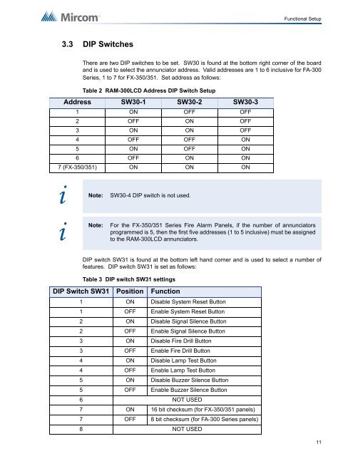
3.3 DIP Switches<br />
There are two DIP switches to be set. SW30 is found at the bottom right corner of the board<br />
<strong>and</strong> is used to select the annunciator address. Valid addresses are 1 to 6 inclusive for FA-300<br />
Series, 1 to 7 for FX-350/351. Set address as follows:<br />
Table 2 <strong>RAM</strong>-<strong>300LCD</strong> Address DIP Switch Setup<br />
Address SW30-1 SW30-2 SW30-3<br />
1 ON OFF OFF<br />
2 OFF ON OFF<br />
3 ON ON OFF<br />
4 OFF OFF ON<br />
5 ON OFF ON<br />
6 OFF ON ON<br />
7 (FX-350/351) ON ON ON<br />
i<br />
Note:<br />
SW30-4 DIP switch is not used.<br />
i<br />
Note:<br />
For the FX-350/351 Series Fire Alarm Panels, if the number of annunciators<br />
programmed is 5, then the first five addresses (1 to 5 inclusive) must be assigned<br />
to the <strong>RAM</strong>-<strong>300LCD</strong> annunciators.<br />
DIP switch SW31 is found at the bottom left h<strong>and</strong> corner <strong>and</strong> is used to select a number of<br />
features. DIP switch SW31 is set as follows:<br />
Table 3 DIP switch SW31 settings<br />
DIP Switch SW31 Position Function<br />
1 ON Disable System Reset Button<br />
1 OFF Enable System Reset Button<br />
2 ON Disable Signal Silence Button<br />
2 OFF Enable Signal Silence Button<br />
3 ON Disable Fire Drill Button<br />
3 OFF Enable Fire Drill Button<br />
4 ON Disable Lamp Test Button<br />
4 OFF Enable Lamp Test Button<br />
5 ON Disable Buzzer Silence Button<br />
5 OFF Enable Buzzer Silence Button<br />
6 NOT USED<br />
7 ON 16 bit checksum (for FX-350/351 panels)<br />
7 OFF 8 bit checksum (for FA-300 Series panels)<br />
8 NOT USED<br />
11