Installation Guide & User Manual - Williams Sound
Installation Guide & User Manual - Williams Sound
Installation Guide & User Manual - Williams Sound

Create successful ePaper yourself
Turn your PDF publications into a flip-book with our unique Google optimized e-Paper software.
<strong>Installation</strong><br />
<strong>Guide</strong> &<br />
<strong>User</strong><br />
<strong>Manual</strong><br />
<strong>Sound</strong>Plus ® WIR TX300 Infrared System<br />
Large Area Infrared Listening System<br />
Modulator Model WIR MOD 1<br />
Transmitter Model WIR TX3<br />
Receiver Models WIR RX1, RX3, RX4<br />
<strong>Williams</strong> <strong>Sound</strong> ®<br />
Helping People Hear<br />
MAN 046C
<strong>Sound</strong>Plus ® WIR TX300 Infrared Listening System<br />
<strong>Installation</strong> and <strong>User</strong> <strong>Manual</strong><br />
Contents:<br />
Page<br />
Introduction 4<br />
Controls and Features<br />
MOD 1 Front Panel 5<br />
MOD 1 Rear Panel 5<br />
TX3 Transmitter 6<br />
Infrared Transmitter Setup<br />
Selecting a Transmitter Location 7<br />
Mounting TX3 Transmitter To Wall or Ceiling 8<br />
Transmitter Power Wiring 9<br />
95 kHz Carrier Cable Connection 10<br />
Modulator <strong>Installation</strong><br />
Power Connection 10<br />
95 kHz Carrier Cable Connection 11<br />
Audio Source Connection 11<br />
Using a Microphone 11<br />
Hi-Pass Filter Setting 11<br />
Testing the System 12<br />
Receiver Instructions 12<br />
Battery Information 13<br />
Suggestions For Receiver Management 14<br />
Troubleshooting 14<br />
Warranty 14<br />
Specifications 15<br />
Note: Taking a few minutes now to read these instructions will save time and ensure proper<br />
system operation.<br />
<strong>Williams</strong> <strong>Sound</strong> ®<br />
Helping People Hear<br />
3
MOD 1 Infrared System Modulator<br />
I<br />
0<br />
Power<br />
Ok<br />
Audio Level<br />
Hi<br />
- +<br />
Adjust<br />
<strong>Williams</strong> <strong>Sound</strong><br />
Infrared<br />
Test Out<br />
Tape<br />
Out<br />
I<br />
0<br />
Power<br />
Ok<br />
Audio Level<br />
Hi<br />
- +<br />
Adjust<br />
Introduction<br />
The <strong>Williams</strong> <strong>Sound</strong> WIR TX300 Infrared System<br />
consists of a MOD 1 Modulator and one or more<br />
TX3 Transmitters (also called emitters) which use<br />
invisible infrared (IR) light waves to broadcast<br />
speech or music to wireless infrared receivers. The<br />
Modulator accepts a variety of audio inputs and<br />
sends a 95 kHz frequency modulated signal to the<br />
Transmitter via a coaxial cable. The Transmitter<br />
emits invisible infrared light into the listening area.<br />
Infrared receivers detect the transmission and<br />
convert the light signals back into audio signals.<br />
The system is designed to broadcast high quality<br />
audio for hearing assistance and language translation<br />
applications. Because the system uses infrared light<br />
for transmission, it is not affected by interference<br />
from radio equipment and does not interfere with<br />
radio equipment.<br />
A single TX3 infrared transmitter will cover<br />
approximately 10,000 square feet of listening area.<br />
Larger areas can be covered with additional<br />
transmitters. The transmission is confined within<br />
opaque walls if security is an issue, such as<br />
courtrooms and corporate boardrooms. The <strong>Williams</strong><br />
<strong>Sound</strong> Infrared System can also be used where<br />
multiple systems are needed in adjacent rooms, such<br />
as movie theaters and conference centers, without<br />
“spillover” from adjacent rooms.<br />
The system can be used with a microphone as a<br />
stand-alone system, or it can be connected to an<br />
existing sound system. Infrared Systems cannot be<br />
used in bright sunlight, which contains large<br />
amounts of interfering infrared light.<br />
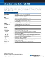
Fig. 1: Typical System Configurations<br />
(1) Modulator and (1) Transmitter<br />
TX3<br />
MOD 1<br />
MOD 1 Infrared System Modulator<br />
<strong>Williams</strong> <strong>Sound</strong><br />
Infrared<br />
Test Out<br />
Tape<br />
Out<br />
Mod Out<br />
<strong>Williams</strong> <strong>Sound</strong> ®<br />
Helping People Hear<br />
Mod In<br />
Power<br />
Supply<br />
Power Supply<br />
(1) Modulator and (2) Transmitters<br />
TX3<br />
TX3<br />
MOD 1<br />
Mod Out<br />
<strong>Williams</strong> <strong>Sound</strong> ®<br />
Helping People Hear<br />
<strong>Williams</strong> <strong>Sound</strong> ®<br />
Helping People Hear<br />
Mod In Mod Out Mod In<br />
Power<br />
Supply<br />
Power Supply<br />
Power<br />
Supply<br />
Modulation Signal<br />
Modulation Signal<br />
4<br />
<strong>Williams</strong> <strong>Sound</strong> ®<br />
Helping People Hear
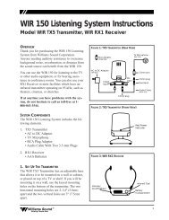
Controls and Features:<br />
MOD 1 Front Panel<br />
Power Switch:<br />
Turns modulator power on/off.<br />
Power Indicator:<br />
Green LED indicates power on.<br />
Audio Level Indicators:<br />
“Ok” amber LED indicates proper audio input level.<br />
“Hi” red LED indicates excessive audio input level.<br />
Audio Level Control:<br />
Screwdriver rotary adjustment for audio input level.<br />
Infrared Test LED:<br />
Infrared LED provides a modulated IR signal for<br />
receiver testing, monitoring, audio source testing.<br />
Tape Output:<br />
RCA Jack provides unbalanced, line-level audio<br />
output signal for tape recorders, etc.<br />
MOD 1 Rear Panel<br />
Balanced Microphone-Level Input:<br />
Female XLR jack for use with low impedance (150 -<br />
200Ω) microphones. Supplies simplex DC power<br />
per DIN 45596 for condenser microphones.<br />
Balanced Line-Level Input:<br />
Female XLR jack for balanced, line-level inputs.<br />
Can also accept unbalanced input, and 4Ω, 8Ω, or<br />
16Ω speaker line.<br />
70V (Hi-Level) Input:<br />
Female XLR jack for direct connection to a 70V or<br />
25V speaker line.<br />
Input Level Switch:<br />
Three-position switch selects mic-level, line-level, or<br />
70V input for the XLR input jack.<br />
Unbalanced Audio Inputs:<br />
Two RCA jacks for unbalanced line-level audio<br />
inputs. Inputs are mixed internally with the balanced<br />
input signal.<br />
High-Pass Filter:<br />
Three position switch provides 6dB/octave lowfrequency<br />
roll-off to reduce noise, improve speech<br />
intelligibility, compensate for typical high-frequency<br />
hearing loss.<br />
Modulator Outputs:<br />
Two F-type connectors provide 95 kHz frequency<br />
modulated outputs to feed two TX3 Transmitters.<br />
Power Input:<br />
Two-screw terminals for low-voltage power supply,<br />
24VAC, 50 or 60Hz, 2.4VA.<br />
Fig. 2: MOD 1 Front & Rear Panels<br />
MOD 1 Infrared System Modulator<br />
<strong>Williams</strong> <strong>Sound</strong><br />
I<br />
0<br />
Power<br />
Audio Level<br />
- +<br />
Ok Hi Adjust<br />
Infrared<br />
Test Out<br />
Tape<br />
Out<br />
Made in USA<br />
Audio Input<br />
Balanced<br />
Mic<br />
Input Level<br />
Line<br />
Model WIR MOD1 Infrared System Modulator<br />
70V<br />
Audio Inputs<br />
Unbalanced<br />
Left<br />
Right<br />
Hi-Pass Filter<br />
175 Hz<br />
20 Hz 725 Hz<br />
6dB/octave<br />
<strong>Williams</strong> <strong>Sound</strong> Corp.<br />
Modulator<br />
Out<br />
75 Ohm<br />
Modulator<br />
Out<br />
75 Ohm<br />
Power: 24 VAC,<br />
50-60 Hz, 10VA<br />
Plug<br />
Power: 24 VAC, 60 Hz, 50VA<br />
<strong>Williams</strong> <strong>Sound</strong> ®<br />
Helping People Hear<br />
5
Modulation Out<br />
RISK OF ELECTRIC SHOCK<br />
DO NOT OPEN<br />
WARNING: TO REDUCE THE RISK OF FIRE OR<br />
ELECTRIC SHOCK DO NOT EXPOSE THIS<br />
EQUIPMENT TO RAIN OR MOISTURE.<br />
Fig. 3: TX3 Front & Rear<br />
<strong>Williams</strong> <strong>Sound</strong> ®<br />
Helping People Hear<br />
Omnimount<br />
25-STXMP<br />
For Ceiling Mount<br />
Infrared Transmitter<br />
Model WIR TX3<br />
Power Supply Wiring:<br />
Use NEC, Class 2 Wiring,<br />
18 ga. Min<br />
200 ft. Max. Length (18 ga.)<br />
Internal Fuse:<br />
1.25 A, 250V, 3AG<br />
Modulation Signal Wiring:<br />
Use RG59U Coax,<br />
1000 ft. Max. Length<br />
Omnimount<br />
25-STXMP<br />
For Wall Mount<br />
Note: It is normal for this unit<br />
to feel warm while it is in<br />
operation.<br />
CAUTION<br />
(75 Ohm)<br />
Modulation In<br />
(75 Ohm)<br />
24 VAC Power In,<br />
50-60 Hz, 35W<br />
<strong>Williams</strong> <strong>Sound</strong> Corp., Minneapolis, Minnesota, USA<br />
Made in U.S.A.<br />
<strong>Williams</strong> <strong>Sound</strong> ®<br />
Helping People Hear<br />
TX3 Transmitter<br />
Power Input:<br />
Two–screw terminal strip for low-voltage power<br />
supply. 24VAC, 50 or 60Hz, 50VA. Each TX3<br />
requires a separate power supply.<br />
Power Indicator LED (front panel):<br />
Located on the front panel in the center of the LED<br />
window. Red indicator light glows when power is on<br />
and the 95 kHz carrier is present.<br />
NOTE: The TX3 shuts off when no 95 kHz carrier<br />
is present.<br />
Modulation In:<br />
Connects to the Modulator Out jack of the MOD 1<br />
modulator or another TX3 transmitter.<br />
Modulation Out:<br />
Connects to the Modulation In jack of of the next<br />
TX3 transmitter in the chain when multiple<br />
transmitters are used.<br />
Mounting Bracket:<br />
An omnidirectional mounting bracket is included<br />
with the Transmitter. Positions are indicated for wall<br />
and ceiling mounts. An optional tripod stand kit is<br />
also available (WSC Part #SS-2).<br />
6<br />
TX3 Front<br />
TX3 Rear<br />
Step 1: Infrared Transmitter<br />
Set-Up<br />
Selecting a Transmitter Mounting<br />
Location<br />
Rule 1: The <strong>Williams</strong> <strong>Sound</strong> Infrared System<br />
should not be installed outdoors or indoors<br />
where there is considerable direct sunlight.<br />
Sunlight generates infrared interference.<br />
Certain types of high-efficiency<br />
fluorescent lighting use 100kHz<br />
modulation that can also interfere with<br />
infrared systems.<br />
Rule 2: The most important principle to<br />
understand when installing an infrared<br />
system is that invisible infrared light<br />
behaves just like visible light. It does not<br />
pass through opaque objects like walls and<br />
curtains and people. It does pass through<br />
windows and door openings and it can<br />
bounce and scatter off reflective walls,<br />
floors, and ceilings. The IR transmitter<br />
panels cannot be concealed or covered up.<br />
The IR “eye” on the receiver unit cannot<br />
be covered up and works best with a clear<br />
line-of-sight to the transmitter panel(s).<br />
Rule 3: If you are not getting sufficient coverage<br />
with a properly installed transmitter panel,<br />
you need to add one or more additional<br />
transmitter panels.<br />
<strong>Williams</strong> <strong>Sound</strong> ®<br />
Helping People Hear
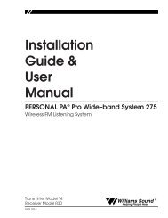
Fig. 4: Infrared Illumination Pattern<br />
TX3<br />
25°<br />
25°<br />
130 ft.<br />
250 ft.<br />
Figures 4, 5, and 6 illustrate infrared light patterns<br />
and recommended transmitter locations. In listening<br />
areas up to 10,000 square feet, the TX3 transmitter<br />
panel should be installed on the left or right side of<br />
the front wall of the listening area It needs to be<br />
above the audience to permit a direct line of sight<br />
between the transmitter and people wearing receivers<br />
when the people are standing or sitting.<br />
It’s helpful to think of the IR transmitter as an<br />
invisible floodlight. You want to aim it so listeners<br />
are “flooded” with infrared light.<br />
Many listening areas will require two IR transmitters<br />
for complete coverage. Place one transmitter panel<br />
on the left side of the front wall and the other on the<br />
right hand side. The two transmitters will be<br />
connected together with a coaxial cable.<br />
Fig. 5: Maximizing Coverage<br />
Top Perspective<br />
Using Two Transmitters For Greater Coverage Area<br />
The infrared illumination pattern from a single<br />
transmitter is a cone-shaped beam, with a 50° angle.<br />
The horizontal and vertical patterns are identical.<br />
Figures 4 and 5 show examples of coverage patterns.<br />
These patterns are the direct radiation pattern. The<br />
infrared radiation does not drop to zero outside the<br />
illustrated patterns; it decreases. It still may be<br />
useable at a greater distance, depending on receiver<br />
sensitivity and reflection characteristics of the room.<br />
Infrared light reflects off light-colored surfaces and<br />
scatters, which increases the coverage area. Dark<br />
colored surfaces tend to absorb infrared light,<br />
minimizing reflections, and limiting coverage to the<br />
direct illumination pattern. It’s O.K. (and desirable)<br />
for the illumination patterns to overlap when<br />
Fig. 6: Side Perspective<br />
120'<br />
Center Of Emitter Beam<br />
30'<br />
6'<br />
SCREEN<br />
STAGE<br />
<strong>Williams</strong> <strong>Sound</strong> ®<br />
Helping People Hear<br />
7
multiple transmitters are used. Placing the<br />
transmitter high above the audience (15 to 30 feet)<br />
and aimed slightly downward (5 to 15°) will ensure<br />
the longest “throw” of the infrared beam. Angling<br />
the transmitter inward towards the center of the room<br />
also increases the coverage of the seating area.<br />
Fig. 7: SB-3 Wall/Ceiling Mount<br />
Mounting Plate<br />
Ballshaft<br />
Clamp Plate<br />
Remember that opaque objects block the infrared<br />
light. Thus, transmitters cannot be concealed behind<br />
an opaque walls, curtains, etc. Neither should<br />
transmitters be used in areas of extreme high or low<br />
temperatures, humidity, or chemical environments.<br />
To<br />
Wall<br />
Or<br />
Ceiling<br />
Jaw<br />
To<br />
Transmitter<br />
Mounting the TX3 to a wall or ceiling:<br />
Step 1: Use the 5/32" allen wrench to loosen the<br />
tension bolt in the clamp assembly enough<br />
to release the ball. DO NOT unscrew the<br />
tension bolt completely. Using the<br />
mounting plate as a template, mark the<br />
hole locations on the mounting surface.<br />
Use fasteners appropriate for the mounting<br />
surface (wood screws, lag bolt, wall<br />
anchor) to attach the mounting plate.<br />
Recommended fastener size is 1/4".<br />
Step 2: Attach the clamp plate to the rear of the<br />
transmitter, using (2) 1/4 x 20 x 1/2"<br />
socket head screws and 3/16 hex wrench<br />
provided. Place the mounting plate in the<br />
position indicated for ceiling or wall<br />
mounting.<br />
Step 3: Place the transmitter/clamp plate assembly<br />
onto the the mounting plate ballshaft. Aim<br />
the transmitter at the desired downward<br />
angle and support it fully while using the<br />
hex wrench to tighten the tension screw.<br />
After initial installation, the ball will<br />
slowly compress under pressure. Check<br />
the tension screw after 15 minutes and retighten<br />
if necessary. DO NOT overtighten.<br />
If rotational adjustment is required, use a<br />
7/16" open-end wrench to loosen the jam<br />
nut on the ballshaft. Rotate the transmitter<br />
and re-tighten the jam nut.<br />
Tension Screw<br />
Fig. 8: Bracket 012 Ceiling Mounting<br />
Fig. 9: Bracket 012 Wall Mounting<br />
Jam Nut<br />
Front of TX3<br />
8<br />
<strong>Williams</strong> <strong>Sound</strong> ®<br />
Helping People Hear
Step 2: Transmitter Power<br />
Wiring<br />
WARNING! BE SURE AC POWER IS TURNED<br />
OFF AT THE OUTLET WHILE INSTALLING THE<br />
POWER TRANSFORMER. A METAL COVER<br />
PLATE COULD SLIP AND SHORT ACROSS THE<br />
TRANSFORMER PLUG DURING INSTALLATION,<br />
CREATING A SHOCK HAZARD.<br />
SHORTING THE POWER SUPPLY TERMINALS<br />
WILL BLOW A NON-REPLACEABLE INTERNAL<br />
FUSE, DESTROYING THE POWER SUPPLY<br />
UNIT1<br />
The TX3 transmitter is supplied with a low-voltage<br />
wall transformer power supply. The transmitter must<br />
be located within 6 feet of an AC wall outlet or the<br />
24 Volt power cord must be extended. Additional<br />
two-conductor, 18 ga. zipcord is included with the<br />
transmitter. If the transmitter power supply can be<br />
located near the modulator, use the combination<br />
cable to carry the modulation signal and low-voltage<br />
power to the transmitter. The zipcord can be<br />
<strong>Williams</strong> separated <strong>Sound</strong> from ® the combination cable if the power<br />
Helping People Hear<br />
Omnimount<br />
supply is located near the transmitter.<br />
25-STXMP<br />
DO NOT CONNECT THE POWER SUPPLY TO<br />
AC POWER YET!!!<br />
Step 1:<br />
Power Supply Wiring:<br />
Use NEC, Class 2 Wiring,<br />
18 ga. Min<br />
200 ft. Max. Length (18 ga.)<br />
Internal Fuse:<br />
1.25 A, 250V, 3AG<br />
Modulation Signal Wiring:<br />
Use RG59U Coax,<br />
1000 ft. Max. Length<br />
For Ceiling Mount<br />
Determine the length of zipcord needed to<br />
reach from the transmitter to the AC wall<br />
outlet where the power supply will be<br />
Omnimount<br />
plugged in. Cut the<br />
25-STXMP<br />
zipcord to length.<br />
Zipcord length must not exceed 200 feet.<br />
For Wall Mount<br />
Strip the ends and install the crimp-on<br />
Step 2:<br />
Infrared Transmitter<br />
Model WIR TX3<br />
spade terminals supplied. Connect one end<br />
of the zipcord to the transmitter power<br />
input screw terminals. Connect the other<br />
end to the power supply screw terminals.<br />
Make sure to.switch AC power to the<br />
outlet OFF at the fuse or circuit breaker.<br />
Remove the wallplate cover screw and<br />
plug the transformer into the outlet.<br />
Secure the transformer with the cover plate<br />
screw. Turn the AC power back on at the<br />
breaker box AFTER the transformer is<br />
installed.<br />
The indicator light on the front panel of<br />
the TX3 will not glow unless there is a<br />
95 kHz carrier. This auto shut-off feature<br />
preserves the life of the IR LED’s and<br />
reduces power consumption when the<br />
transmitter is not in use. The wall<br />
transformer can be plugged into a switched<br />
outlet that turns on when the other sound<br />
equipment is turned on. This system is<br />
designed for Class 2, low-voltage wiring.<br />
Always follow local electrical codes when<br />
doing low voltage wiring.<br />
Note: It is normal for this unit<br />
to feel warm while it is in<br />
operation.<br />
CAUTION<br />
RISK OF ELECTRIC SHOCK<br />
DO NOT OPEN<br />
WARNING: TO REDUCE THE RISK OF FIRE OR<br />
ELECTRIC SHOCK DO NOT EXPOSE THIS<br />
EQUIPMENT TO RAIN OR MOISTURE.<br />
Fig. 10: TX3 Wiring Detail<br />
Modulation Out<br />
(75 Ohm)<br />
Modulation In<br />
(75 Ohm)<br />
24 VAC Power In,<br />
50-60 Hz, 35W<br />
<strong>Williams</strong> <strong>Sound</strong> Corp., Minneapolis, Minnesota, USA<br />
Made in U.S.A.<br />
Baseband Output Connection<br />
Connect to MOD 1 here<br />
using RG-59 cable.<br />
Power Connection<br />
Plug in Power Supply<br />
<strong>Williams</strong> <strong>Sound</strong> ®<br />
Helping People Hear<br />
9
Step 3: 95 kHz Carrier<br />
Cable <strong>Installation</strong><br />
Step 1:<br />
Step 2:<br />
Step 3:<br />
Determine the length of RG59 coaxial<br />
cable needed to reach from the transmitter<br />
to the modulator unit. The modulator is<br />
usually located near the other sound<br />
equipment to simplify audio connections.<br />
100 feet of coaxial cable is included with<br />
each transmitter. You will need to cut it to<br />
length and install F-connectors on both<br />
ends. Additional RG59 coax can be added,<br />
up to 1000 feet maximum. Make sure you<br />
leave some slack at each end.<br />
Install the F-connectors on each end of the<br />
cable. You will need a CATV-type coax<br />
stripper and crimper.<br />
Connect the 95 kHz carrier cable to either<br />
Modulator Out jack on the MOD 1<br />
modulator and to the Modulator In jack on<br />
the TX3 transmitter.<br />
If you are using more than one transmitter:<br />
Step 1: Determine the length of coaxial cable<br />
needed to reach between the transmitters.<br />
100 feet of coaxial cable is included with<br />
each transmitter. You will need to cut it to<br />
length and install F-connectors on both<br />
ends. Additional RG59 coax can be added,<br />
up to 1000 feet maximum. Make sure you<br />
leave some slack at each end.<br />
Step 2: Install the F-connectors on each end of the<br />
cable. You will need a CATV-type coax<br />
stripper and crimper.<br />
Step 3:<br />
Connect the modulation cable from the<br />
Modulation Out Jack on the first<br />
transmitter in the chain (the one connected<br />
to the MOD 1 Modulator) to the<br />
Modulation In jack on the next TX3<br />
transmitter in the chain. Use the cable<br />
clamps and screws provided to secure the<br />
cable. The coax can also be routed through<br />
conduit. You can chain as many<br />
transmitters together as you need.<br />
Remember that each transmitter needs its<br />
own power supply.<br />
Fig. 11: Modulator Wiring Detail<br />
Made in USA<br />
Audio Input<br />
Balanced<br />
Mic<br />
Input Level<br />
Line<br />
Model WIR MOD1 Infrared System Modulator<br />
70V<br />
Audio Inputs<br />
Unbalanced<br />
Left<br />
Right<br />
Hi-Pass Filter<br />
175 Hz<br />
20 Hz 725 Hz<br />
6dB/octave<br />
<strong>Williams</strong> <strong>Sound</strong> Corp.<br />
Modulator<br />
Out<br />
75 Ohm<br />
Modulator<br />
Out<br />
75 Ohm<br />
Power: 24 VAC,<br />
50-60 Hz, 10VA<br />
Plug<br />
Power: 24 VAC, 60 Hz, 50VA<br />
Baseband Output Connection<br />
Connect to TX3 here using RG-59 cable.<br />
Power Connection<br />
Plug in Power Supply<br />
10<br />
<strong>Williams</strong> <strong>Sound</strong> ®<br />
Helping People Hear
Step 4: MOD 1 Modulator<br />
<strong>Installation</strong><br />
Location:<br />
The Modulator is usually located near the sound<br />
system amplifier or mixer for easy access to an audio<br />
input signal. For portable systems, the modulator can<br />
be placed near the transmitter or wherever is most<br />
convenient.<br />
Power Connection<br />
Step 1: Connect the power supply wires to the two<br />
center screw terminals on the terminal<br />
block located on the rear of the Modulator.<br />
Step 2: Plug the power supply into an AC outlet.<br />
95 kHz Cable Connection<br />
Connect the coaxial cable to either F-type<br />
“Modulator Out” jack on the MOD 1. For systems<br />
having multiple transmitters, both modulator outputs<br />
can be used to run a separate coax cable to<br />
transmitters on each side of a stage, screen, etc. The<br />
MOD 1 drives one transmitter per modulator output.<br />
The transmitters then repeat the 95 kHz signal, so<br />
any number of transmitters can be used. The<br />
modulator outputs CANNOT be split with CATV<br />
splitters.<br />
Audio Connection<br />
Mono, Unbalanced Source:<br />
Use the RCA to RCA audio cable supplied to<br />
connect either MOD 1 unbalanced “Audio Input”<br />
jack to an appropriate unbalanced, line-level audio<br />
output jack on the sound system mixer or amplifier.<br />
Suitable connections are:<br />
1st Choice:<br />
2nd Choice:<br />
TAPE OUT or LINE OUT Jack<br />
BOOSTER or BRIDGING Jack<br />
If your amplifier or mixer does not have RCA-type<br />
connectors, you can obtain adaptors from your<br />
<strong>Williams</strong> <strong>Sound</strong> Authorized Dealer or a local radio<br />
parts store. If the TAPE OUT jack is already in use,<br />
a Y-Cord can be used to connect the MOD 1 and a<br />
second device to the same jack.<br />
Stereo, Unbalanced Source:<br />
For stereo sources, use an additional RCA to RCA<br />
cable and connect the left and right signals to the two<br />
inputs on the MOD 1. They will be mixed into a<br />
mono signal for transmission.<br />
Three–Channel, Unbalanced Source<br />
(Left, Right, Center Channel):<br />
Set the input level switch to “Line.” Use the two<br />
unbalanced inputs and the XLR balanced input. You<br />
will have to make an RCA to XLR adaptor cable. To<br />
unbalance the XLR input, wire XLR pin 2 to the<br />
positive audio pin on the RCA plug and wire XLR<br />
pin 1 and pin 3 together to the audio ground sleeve<br />
on the RCA plug. The three signals will be mixed<br />
into a mono signal for transmission.<br />
Balanced, Line–Level Source:<br />
Set the Input Level Switch to “Line.” The XLR input<br />
jack can be connected to any balanced, line-level<br />
audio signal. It has an input impedance of<br />
100 KOhms, so it will not load the signal.<br />
Balanced, Microphone Source:<br />
Set the Input Level switch to “Mic.” Any lowimpedance,<br />
balanced microphone can be plugged<br />
into the XLR input jack. Simplex power is supplied<br />
for condenser microphones.<br />
4 or 8 Ohm Speaker Line Source:<br />
Set the Input Level Switch to “Line.” Wire an<br />
adaptor cable with the positive speaker line<br />
connected to XLR pin 2. Connect the negative or<br />
ground speaker line to XLR pin 3.<br />
25 or 70V Speaker Line Source:<br />
Set the Input Level Switch to “70V.” Wire an adaptor<br />
cable with the positive speaker line connected to<br />
XLR pin 2. Connect the negative or ground speaker<br />
line to XLR pin 3.<br />
Hi-Pass Filter Setting<br />
The normal setting is the center (175Hz) position.<br />
For language interpretation or visual description, the<br />
20Hz setting can be used. For hearing assistance, the<br />
725Hz setting can be used to compensate for typical<br />
high-frequency hearing loss. Ask the users what<br />
sounds best to them.<br />
<strong>Williams</strong> <strong>Sound</strong> ®<br />
Helping People Hear<br />
11
Step 5: Testing the System<br />
Step 1:<br />
Step 2:<br />
Step 3:<br />
Step 4:<br />
Step 5:<br />
After the 95 kHz carrier cable, power<br />
cables, and audio source are connected,<br />
turn the MOD 1 power switch on. The<br />
green LED on the front of the MOD 1<br />
should light.<br />
Make sure the sound system is on and your<br />
audio source is active. Adjust the Audio<br />
Level control on the front of the MOD 1<br />
until the “OK” light flashes with the audio<br />
signal. It is okay if the red “Hi” light<br />
flashes occasionally, but it should not stay<br />
lit constantly. If you can't get the “Ok”<br />
light to come on, make sure the Input<br />
Level switch is set properly. If it is, you<br />
need to boost the signal source.<br />
Look at the transmitter panel(s). With the<br />
modulation signal and power connected, a<br />
red light should be visible in the center of<br />
the panel.<br />
Hold a receiver near the “Infrared Test<br />
Out” hole on the front of the MOD 1. Turn<br />
the receiver on and adjust the volume. You<br />
should be able to hear the audio signal<br />
through the receiver. If not, make sure the<br />
audio “Ok” light is still flashing. If the<br />
light is not flashing, check your audio<br />
source or the setting of the input level<br />
switch and input level control. If the audio<br />
light is flashing, but you don’t hear<br />
anything from the receiver, try a different<br />
receiver to make sure the receiver is<br />
working.<br />
Take a receiver into the listening area and<br />
walk around to check the reception. Make<br />
sure the “eye” on the receiver is not<br />
covered up when in use. The receiver will<br />
not work if it is placed in a pocket or<br />
purse. The receiver eye must be able to<br />
“see” the transmitter panel. It may be<br />
necessary to adjust the angle of the<br />
transmitter(s) to obtain the best coverage.<br />
If coverage is not adequate, additional<br />
transmitter panels must be used.<br />
Receiver Operating<br />
Instructions<br />
Receiver Model WIR RX1<br />
The RX1 is a stethoscope-style receiver with built-in<br />
earphones. Make sure the “eye” on the front of the<br />
receiver is not covered up when in use. The receiver<br />
is intended to be worn on the front of the body,<br />
hanging from the ears.<br />
Step 1:<br />
Step 2:<br />
Battery <strong>Installation</strong>: The RX1 uses two<br />
AAA Alkaline batteries. To insert, remove<br />
the cover, press the batteries into<br />
place,then replace the cover.<br />
Turn the power on by rotating the volume<br />
control. Continue rotating until a<br />
comfortable volume level is reached. To<br />
avoid draining the battery, make sure the<br />
receiver is turned off when not in use.<br />
Receiver Model WIR RX3<br />
Make sure the “eye” on the front of the receiver is<br />
not covered up when in use. The receiver is intended<br />
to be worn on the front of the body, hanging from the<br />
lanyard attached to the receiver. The receiver will not<br />
work if it is placed in a pocket or purse. A variety of<br />
earphones, headphones, or a neckloop telecoil<br />
coupler can be used with the RX3 Receiver.<br />
Step 1:<br />
Step 2:<br />
Step 3:<br />
Battery <strong>Installation</strong>: Open the battery<br />
compartment by lifting the tab at the<br />
bottom of the receiver. Press the battery<br />
into place, observing proper battery<br />
polarity.<br />
Plug the earphone or headphone into the<br />
earphone jack.<br />
Turn the receiver on by rotating the<br />
volume control in the direction of the<br />
arrow on top of the case. Turning the knob<br />
in the direction of the arrow will increase<br />
the volume. Turning the knob against the<br />
arrow will decrease the volume. To avoid<br />
draining the battery, make sure the receiver<br />
is turned off when not in use.<br />
12<br />
<strong>Williams</strong> <strong>Sound</strong> ®<br />
Helping People Hear
Receiver Model WIR RX4<br />
The RX4 is a headset-style receiver. Make sure the<br />
“eye” on top of the receiver is not covered up when<br />
in use.<br />
Step 1:<br />
Step 2:<br />
Battery <strong>Installation</strong>: Open the battery<br />
compartment by sliding the battery door<br />
open on the earpiece. Press two AAA<br />
batteries into place, observing proper<br />
battery polarity. Slide the battery door<br />
closed, taking care not to crush the plastic<br />
locking tabs.<br />
Turn the power switch on top of the<br />
receiver on. Adjust the volume control<br />
wheel located on the bottom of the<br />
headset.<br />
leaving the receiver on for several hours and then<br />
immediately recharge it.<br />
Receivers can be left charging continuously when<br />
not in use.<br />
DO NOT ATTEMPT TO RECHARGE DISPOSABLE<br />
BATTERIES!<br />
AVOID SHORTING PLUS AND MINUS BATTERY<br />
TERMINALS TOGETHER WITH METAL OBJECTS.<br />
BATTERY DAMAGE AND BURNS CAN RESULT!<br />
DO NOT MIX RECHARGEABLE BATTERIES &<br />
CHARGERS FROM DIFFERENT<br />
MANUFACTURERS.<br />
Battery Information for Receivers<br />
For the RX3 Receiver in normal use, a heavy-duty 9<br />
Volt battery such as the Eveready 216 will last about<br />
10 hours. Alkaline batteries such as the Eveready<br />
522 will provide about 17 hours of use. For the RX4,<br />
alkaline AAA batteries will last about 20 hours. If<br />
the sound becomes weak or distorted, replace the<br />
battery. The indicator light may still be on, even<br />
with a battery that is weak. Do not leave dead<br />
batteries in the receivers, they may leak and damage<br />
the receiver.<br />
Rechargeable Batteries:<br />
The RX3 receivers can also use a rechargeable<br />
battery. We recommend only the 7-cell, 8.4 Volt<br />
types<br />
(BAT 003). A fully-charged battery (<strong>Williams</strong> BAT<br />
003) will provide about 5 hours of use per charge.<br />
The battery may be recharged without removing it<br />
from the receiver.<br />
The BAT 005 Single Charger has a cord that plugs<br />
into the receiver “EAR” jack to charge the battery.<br />
The CHG 1269 Multiple Charger can charge 12<br />
receivers simultaneously through the receiver “EAR”<br />
jacks.<br />
The receiver should always be turned OFF while<br />
charging. It takes about 14 hours to fully charge the<br />
battery. If the battery is providing very short service<br />
life (under 1 hour of use) let it drain completely by<br />
<strong>Williams</strong> <strong>Sound</strong> ®<br />
Helping People Hear<br />
13
Suggestions for Receiver<br />
Management:<br />
Different types of facilities will use different<br />
approaches for receiver management and earphone<br />
sanitation. Following are some alternatives that other<br />
customers have used successfully:<br />
1. Regular users purchase their own receiver and<br />
take care of their own batteries and earphone.<br />
2. Some facilities label the receiver and earphone<br />
with the names of regular users so each person<br />
uses the same receiver and earphone.<br />
3. Ushers issue receivers to people who request<br />
them. Earphones are sanitized after use. Foam<br />
ear cushions can be replaced or washed with a<br />
mild detergent, rinsed thoroughly and airdried.<br />
The EAR 022 Surround Earphone can<br />
be sanitized with an alcohol pad.<br />
4. The receivers are stored in a multiple<br />
compartment storage case with a credit card or<br />
driver's license left as collateral for the<br />
receiver.<br />
5. Regular users purchase their own earphone or<br />
headphone and bring them to use with<br />
receivers at the facility.<br />
Troubleshooting:<br />
Transmitter “Power” light not on.<br />
1. Make sure the wall transformer is plugged into<br />
the transmitter and the power switch or any<br />
remote power switch is on..<br />
2. Make sure the electrical outlet is on.<br />
3. Make sure the MOD1 is on. The TX3 shuts off<br />
when there is no 95kHz modulation signal.<br />
4. Make sure the 24VAC power supplies are<br />
working.<br />
No sound through receivers.<br />
1. If some of the receivers work but others don’t,<br />
check for bad batteries or earphones on the<br />
receivers that aren’t working.<br />
2. If none of the receivers work, check to see if<br />
the power and 95 kHz carrier cable are<br />
connected to the transmitter and the “Power”<br />
like is ON.<br />
3. Check to see if the modulator is connected<br />
properly to the sound system. The audio level<br />
lights should be flashing on the modulator.<br />
4. Make sure the “eye” is not covered up on the<br />
receiver. There must be clear line of sight<br />
between the receiver eye and the transmitter<br />
panel.<br />
<strong>Sound</strong> through the receivers is weak<br />
and noisy.<br />
1. Hold a receiver in front of the Infrared Test<br />
LED on the front of the MOD 1 modulator and<br />
listen to the signal. If the signal is weak and<br />
noisy here, check the Input Level switch and<br />
Input Level Control settings. Increase the input<br />
signal level from the sound system by turning<br />
up a mixer control. If the signal sounds okay,<br />
you may need to re-position the transmitter<br />
panels or add additional panels.<br />
Buzzing or humming noise in sound<br />
system.<br />
1. Check for ground loops or noise on the input<br />
signal. Call your Authorized Dealer or<br />
<strong>Williams</strong> <strong>Sound</strong> for help.<br />
Warranty<br />
<strong>Williams</strong> <strong>Sound</strong> Transmitters and Receivers are<br />
warranted against defects in workmanship and<br />
materials for FIVE YEARS. Microphones,<br />
earphones, cables, carry cases, rechargeable batteries<br />
and chargers are warranted against defects in<br />
workmanship and materials for 90 DAYS. This<br />
warranty does not extend to intentional or accidental<br />
physical damage. This warranty applies only to<br />
products returned to <strong>Williams</strong> <strong>Sound</strong> for service. To<br />
return a product for service, call <strong>Williams</strong> <strong>Sound</strong><br />
Corp. at 1-800-843-3544 and request a Return<br />
Authorization (RA) number.<br />
14<br />
<strong>Williams</strong> <strong>Sound</strong> ®<br />
Helping People Hear
<strong>Sound</strong>Plus WIR TX300 Infrared Listening System Specifications<br />
Infrared Audio Processor/Modulator, Model MOD 1<br />
Dimensions, Weight:<br />
Color:<br />
Rack Mount:<br />
Power:<br />
Modulation:<br />
AGC:<br />
Operating Req.:<br />
8.45" (21.5 cm) W x 8.18" (20.8 cm) D x<br />
1.72" (4.4 cm) H, 3 lbs. (1.5 kg)<br />
Black epoxy paint with white legends<br />
One IEC rack space high, one or two<br />
units can be mounted in a single rack<br />
space with optional RPK 005 (single) or<br />
RPK 006 (double) Rack Mount Kits<br />
External power supply, 24VAC, 50 or<br />
60Hz, 2.4VA, 82mA max. current drain<br />
95kHz FM, ± 15kHz deviation, 75Ω source<br />
impedance, 75µsec pre-emphasis,<br />
Variable slope compressor/limiter<br />
0-50°C ambient temperature, noncondensing,<br />
non-corrosive atmosphere<br />
Front Panel:<br />
Power Switch:<br />
Two-position rocker, ON/OFF<br />
Power Indicator: Green LED<br />
Audio Indicators: Amber LED "Ok" for nominal input signal<br />
level<br />
Red LED "Hi" for excessive input signal level<br />
Audio Level Control: Rotary pot, screwdriver adjust, used<br />
with audio indicator lights<br />
Tape Output:<br />
RCA jack, 600mV, 1200Ω source<br />
impedance, 10KΩ nominal load<br />
impedance<br />
Infrared Test LED: IR LED for receiver testing, monitoring,<br />
and audio signal testing<br />
Rear Panel:<br />
Audio Inputs:<br />
Balanced Audio In:<br />
Mic Input:<br />
Line Input:<br />
All three inputs are actively mixed into a<br />
single signal, allowing use of mono,<br />
stereo, or 3 channel audio sources<br />
3-pin female XLR, accepts microphone,<br />
line, 25V or 70V audio input<br />
lo-Z, 100µV min. to 50mV max. 1mV<br />
nominal, 3kΩ input impedance Supplies<br />
simplex power 20V (DIN45296) for<br />
condenser mics<br />
21mV min. to 10V max., 212mV nominal,<br />
100KΩ input impedance<br />
70 Volt Input: 216mV min. to 100V max., 2.16V<br />
nominal, 100KΩ input impedance<br />
Unbalanced Audio Ins: (2) RCA, 21mV min. to 10V max., 212mV<br />
nominal, 50KΩ input impedance<br />
Input Selector:<br />
3-position slide-type switch, selects:<br />
mic/line/70V on balanced audio input<br />
High-Pass Filter: 3-position slide-type switch, 20Hz, 175Hz,<br />
or 725Hz, 6dB/octave roll-off<br />
Modulation Outputs: (2) F-type connectors, 75Ω, 95kHz FM,<br />
±15kHz deviation, 0.5V P-P signal uses<br />
RG-59 cable, 1000 ft. (304 m) max.<br />
CATV splitters cannot be used<br />
Power Connections: 2-conductor, screw-terminals<br />
Transmitter Type: For use with <strong>Williams</strong> <strong>Sound</strong> WIR TX1, WIR<br />
TX2, WIR TX3 Transmitter/Emitter panels.<br />
Each MOD 1 Modulator can drive two<br />
Transmitter panels directly. For multitransmitter<br />
systems, each TX3 repeats<br />
the modulation signal to drive the next<br />
transmitter in the chain.<br />
Infrared Transmitter, Model TX3<br />
Dimensions, Weight:<br />
Color:<br />
Wall Mount:<br />
Tripod Mount:<br />
Power:<br />
Operating Req.:<br />
Coverage Area:<br />
11.125" (28.3 cm) W x 8.125" (20.6 cm)<br />
H x 3.25" (8.3 cm) D, 3.25 lbs. (1.6 kg)<br />
Black epoxy paint with white legends,<br />
red acrylic window<br />
Omnidirectional mount included for<br />
wall and ceiling mounting.<br />
Optional SS-2 Tripod Stand Kit available<br />
External power supply, 24VAC, 50 or<br />
60Hz, 50VA, 0.9A nom. current drain<br />
Transmitter shuts off when modulation<br />
signal is not present<br />
0-50° C ambient temperature, noncondensing,<br />
non-corrosive atmosphere<br />
10,000 sq. ft. (930 sq. m), 50° cone<br />
pattern, see coverage diagram<br />
TX3 Front Panel:<br />
Power Indicator:<br />
TX3 Rear Panel:<br />
Mounting Holes:<br />
Red LED, visible in center of window,<br />
also indicates 95 kHz signal is present<br />
Two sets of threaded holes for use with<br />
omnidirectional mount (included) two<br />
threaded holes on sides of the cabinet<br />
for Tripod Stand Kit<br />
Modulation Input: F-type connector, 75Ω, 95kHz FM, 0.5V<br />
P-P signal from MOD 1 Modulator<br />
Modulation Output: F-type connector, 75Ω, 95kHz FM, 0.5V<br />
P-P signal output to additional TX3<br />
Power Connection: 2-conductor, screw-terminals<br />
95 kHz Carrier Cable: RG-59 Coax, F-connectors<br />
Power Cable:<br />
NEC Class 2 wiring, 2-conductor, 18 ga.<br />
min., 200 foot (61 m) max. length (for<br />
18 ga. wire), each TX3 Transmitter<br />
requires its own 24VAC Power Supply.<br />
<strong>Williams</strong> <strong>Sound</strong> ®<br />
Helping People Hear<br />
15
<strong>Williams</strong> <strong>Sound</strong> Corp.<br />
10321 West 70th St., Eden Prairie, MN 55344-3446<br />
U.S.A. 800-843-3544 / 952-943-2252 / FAX: 952-943-2174<br />
© 1996, <strong>Williams</strong> <strong>Sound</strong> Corp. MAN 046C