Installation Guide & User Manual - Williams Sound
Installation Guide & User Manual - Williams Sound
Installation Guide & User Manual - Williams Sound
- No tags were found...

Create successful ePaper yourself
Turn your PDF publications into a flip-book with our unique Google optimized e-Paper software.
<strong>Installation</strong><br />
<strong>Guide</strong> &<br />
<strong>User</strong><br />
<strong>Manual</strong><br />
PERSONAL PA ® Pro Wide–band System 275<br />
Wireless FM Listening System<br />
Transmitter Model T4<br />
Receiver Model R30<br />
<strong>Williams</strong> <strong>Sound</strong> ®<br />
Helping People Hear<br />
MAN 103 A
PRO WIDE–BAND SYSTEM, MODEL PPA 275<br />
INSTALLATION GUIDE & USER MANUAL<br />
Contents<br />
Page<br />
FAST SET-UP PROCEDURE 4<br />
SYSTEM OVERVIEW 6<br />
CONTROLS AND CONNECTORS 8<br />
DETAILED SET-UP PROCEDURE 4<br />
MOUNTING THE TRANSMITTER<br />
INSTALLING THE ANTENNA<br />
CHOOSING A CHANNEL<br />
CHOOSING AND CONNECTING AN AUDIO SOURCE<br />
CHOOSING AN AUDIO SOURCE FOR THE HEARING IMPAIRED<br />
CONNECTING THE POWER SUPPLY<br />
ADJUSTING THE AUDIO INPUT CONTROL<br />
AUDIO PROCESSOR OPTIONS 16<br />
ASSURING EXCELLENT PERFORMANCE 17<br />
RECEIVER USE INSTRUCTIONS 18<br />
BATTERY INFORMATION 19<br />
RADIO INTERFERENCE TUNING INSTRUCTIONS 20<br />
SUGGESTIONS FOR RECEIVER MANAGEMENT 21<br />
TROUBLESHOOTING GUIDE 22<br />
WARRANTY 25<br />
SYSTEM SPECIFICATIONS 26<br />
<strong>Williams</strong> <strong>Sound</strong> ®<br />
Helping People Hear<br />
3
FAST SETUP PROCEDURE<br />
Step 1<br />
Choose a Location for the Transmitter<br />
It’s usually most convenient to locate the T4 next to the public address equipment. The<br />
location must have the audio feed and 120 VAC power available. Place the transmitter on a<br />
level surface where there are no substantial metal or other electrically conductive objects<br />
between the antenna and the listening area.<br />
After initial adjustments, there should be no need to access the unit.<br />
Step 2<br />
Choose a Location and Install the Antenna<br />
The T4 is equipped with a short flexible antenna (ANT 021). The ANT 021 threads onto a<br />
stud recessed in a hole on the top of the transmitter. Do not use excessive force to tighten the<br />
antenna; it need only be finger tight.<br />
The T4 Transmitter can also be purchased with a coaxial antenna (ANT 005) or Wall Mount<br />
Dipole Antenna (ANT 024).<br />
See Remote Antenna Location Tips on page 11 for more detail.<br />
Step 3<br />
Choose a Channel<br />
Both the T4 Transmitter and R30 Receivers are set to 72.9 MHz at the factory, unless<br />
otherwise specified. However, you may easily set the T4 to any of the 10 available channels<br />
using the FM Channel/FM Power Switch. You may wish to use a different channel if there is<br />
already another hearing assistance system or some other authorized radio service operating<br />
on 72.9 MHz in your area.<br />
Receivers must also be set to the same frequency as the transmitter. See page 22 for receiver<br />
tuning instructions.<br />
Step 4<br />
Choose and Connect an Audio Source<br />
Plug the T4’s audio cable into a Line Out, Record Out, Tape Out or Auxiliary Out jack on<br />
your system amplifier. If these outputs are already in use, a simple Y–cord can be used to<br />
make the connection. Plug the other end of the audio cable into the T4’s Audio Input Jack on<br />
the rear panel. If all line level outputs are in use, the T4’s line out jack on the transmitter’s<br />
rear panel can be used to feed other devices.<br />
IMPORTANT: If you choose to connect to 70 Volt Speaker line, be certain to set the<br />
Audio Config switch correctly. Transmitter damage will occur if you do not.<br />
4<br />
<strong>Williams</strong> <strong>Sound</strong> ®<br />
Helping People Hear
Step 5<br />
Set the Audio Select DIP Switches<br />
Set the Audio Select switch for the type of source you’re using.<br />
If you have used the audio cable provided with the PPA 275, there is no need to change<br />
the factory set configuration.<br />
If you have used a different type of cable, see the T4’s top panel and pages 10 and 13 for the<br />
appropriate switch configurations and plug wiring diagrams. See page 15 for Compress vs.<br />
Limit adjustments.<br />
Step 6<br />
Connect the Power Supply<br />
Plug the T4’s transformer into a standard 120 VAC outlet and connect the attached cable to<br />
the transmitter. The cable connector has a retaining catch which must be installed toward the<br />
top of the transmitter as illustrated on the T4’s back panel. The T4 will not operate if you<br />
install the cable upside down, though no damage will result.<br />
Neither the T4, nor its power supply, are equipped with a power switch. Because there is no<br />
“wear out” mechanism and power consumption is minimal, continuous operation is not a<br />
problem.<br />
Step 7<br />
Adjust the Audio Input Control<br />
Play a compact disc or other good audio source through the complete sound system at a level<br />
that is typical of normal operation.<br />
Adjust the Audio Input control so that the Level Indicator 0 dB LED generally lights and the<br />
+6 dB LED lights occasionally.<br />
Step 8<br />
Listen with the Receiver<br />
Install the batteries, plug in the earphone, turn on the receiver and walk around the listening<br />
area. The signal should be clear and quite loud when the volume is turned up. See page 17<br />
for performance checks.<br />
For more detailed installation procedures, see page 11. For more detailed system description,<br />
see page 8.<br />
<strong>Williams</strong> <strong>Sound</strong> ®<br />
Helping People Hear<br />
5
Frequency Synthesized, Channel-Selectable<br />
Decrease<br />
Increase<br />
Lo Ok<br />
Ok<br />
Too Hi<br />
SYSTEM OVERVIEW<br />
The PPA 275 is a Wide-band FM Listening System which operates in the 72–76 MHz<br />
frequency band.<br />
Developed for hearing assistance in places of public access, the PPA 275 is designed for<br />
those who need help overcoming background noise, reverberation, or distance from the<br />
sound source. It includes a complete audio processor optimized for the needs of hearing<br />
impaired persons and is easily integrated with your existing sound system. The PPA 275 can<br />
also be used with a microphone as a stand-alone system.<br />
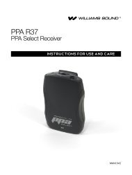
Your PPA 275 has two principle parts: the T4 Transmitter and the R30 Receivers. Much like<br />
a miniature radio station, the transmitter and microphone pick up the sounds you want to hear<br />
and broadcast them over an FM radio signal. The receivers pick up the broadcast up to 500<br />
feet away.<br />
Listeners may sit anywhere and can make the audio signal as loud as they wish without<br />
causing PA system feedback or disturbing others.<br />
To avoid difficulties, read through this manual as you begin to use the system. Then save it<br />
for questions that arise as you continue to use your PPA system.<br />
If you have any problems with this <strong>Williams</strong> <strong>Sound</strong> product, don’t hesitate to call us toll-free<br />
at 1-800-843-3544.<br />
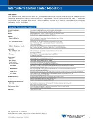
FIGURE 1: OVERALL SYSTEM DIAGRAM<br />
Microphones<br />
Loudspeakers<br />
Line-Level<br />
Output<br />
<strong>Sound</strong> System Amplifier<br />
Line-Level<br />
Input<br />
PPA T4 Professional FM Auditory Assistance Transmitter<br />
Audio Adjust<br />
Audio Level<br />
Power -12dB -6dB 0dB +6dB<br />
RF Carrier<br />
<strong>Williams</strong> <strong>Sound</strong><br />
T4 Transmitter<br />
Phones<br />
R30 Receivers<br />
w/Earphones<br />
6<br />
<strong>Williams</strong> <strong>Sound</strong> ®<br />
Helping People Hear
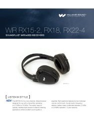
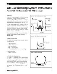
FIGURE 2: T4 TRANSMITTER CONTROLS & FEATURES<br />
Audio Level Indicators<br />
Four-LED array shows audio level in 6 dB steps. Optimum level<br />
is reached when the amber 0 light usually blinks and the red +6<br />
light blinks occasionally.<br />
Phones Jack<br />
1/4" jack, 220 Ω source impedance. Drives mono or stereo<br />
headphone. Monitors exactly what is being transmitted.<br />
PPA T4 Professional FM Auditory Assistance Transmitter<br />
Frequency Synthesized, Channel-Selectable<br />
Audio Adjust<br />
Audio Level<br />
Power -12dB -6dB 0dB +6dB<br />
RF Carrier<br />
<strong>Williams</strong> <strong>Sound</strong><br />
Phones<br />
Decrease<br />
Increase<br />
Lo<br />
Ok<br />
Ok<br />
Too Hi<br />
Power On Indicator<br />
Green LED<br />
Audio Level Control<br />
Rotary pot, screwdriver adjust,<br />
used with audio level indicator lights<br />
RF Indicator<br />
Green LED indicates transmitter RF is on<br />
Audio Select Switches<br />
DIP switch, sets input characteristics, audio<br />
processing mode, and input filter cutoff<br />
frequency. (See top panel chart or Figure 3)<br />
Line Out<br />
Line level output of the fully<br />
processed, as transmitted, audio.<br />
Can be used for monitoring,<br />
recording, or as a feed for other<br />
equipment.<br />
Audio Select<br />
Audio Input<br />
(XLR) Bal. Mic<br />
Bal./Unbal line or 70V<br />
(TRS) Bal./Unbal .<br />
Line or 70V<br />
Line Out<br />
Model PPA T4 Auditory Assistance FM Transmitter<br />
FM Channel,<br />
Power<br />
<strong>Williams</strong> <strong>Sound</strong> Corp., Minneapolis, MN USA<br />
Antenna<br />
Power: 24 VAC,<br />
50-60 Hz, 10VA<br />
1 2 3 4 5 6 7 8 1 2 3 4 5 6 7 8<br />
To configure, see chart on top.<br />
See chart on top.<br />
75 Ohms<br />
Plug<br />
Balanced/Unbalanced Audio Input<br />
Combination 3-pin female XLR/1/4" stereo jack, accepts<br />
balanced or unbalanced microphone and line level inputs,<br />
25 V or 70 V audio input<br />
IMPORTANT: If you choose to connect to 70 Volt<br />
Speaker line, be certain to set the Audio Select switch<br />
correctly. Transmitter damage will occur if you do not.<br />
FM Channel/FM Power Switches<br />
DIP switch for setting channel frequency and<br />
RF output power level. See chart on top of<br />
unit for switch configurations (Fig. 3, page 8).<br />
Power<br />
Connection<br />
3-pin, Molex<br />
connector for TFP<br />
016 power supply<br />
<strong>Williams</strong> <strong>Sound</strong> ®<br />
Helping People Hear<br />
7
CONTROLS AND CONNECTORS<br />
FRONT PANEL<br />
POWER INDICATOR<br />
Indicates that the transmitter has power available and that the unit is on.<br />
AUDIO ADJUST CONTROL<br />
Controls level of audio signal and is connected between the input amplifier and the audio<br />
level processing circuit.<br />
AUDIO LEVEL INDICATOR<br />
A four-LED array shows audio level in 6 dB steps. Indicator is average responding and is<br />
calibrated so that optimum level is reached when the amber 0 light usually blinks and the red<br />
+6 light blinks occasionally.<br />
RF CARRIER INDICATOR<br />
The RF Carrier On Indicator shows when the transmitter is actually transmitting.<br />
PHONES JACK<br />
The Phones Jack monitors the processed, “as transmitted” audio. It accommodates standard<br />
professional headphones with a 1/4" inch Tip-Ring-Sleeve (Stereo) plug. It can accept any<br />
other type of headphone or earphone including those with Tip-Sleeve (Mono) plugs.<br />
Earphones with 3.5 mm plugs can be used with a suitable adapter (i.e., Radio Shack Part<br />
#274-367). Listening to this signal gives an accurate indication of the audio actually heard by<br />
users.<br />
REAR PANEL<br />
AUDIO SELECT SWITCH<br />
Input characteristics, audio processing mode, and input filter cutoff frequency are set by this<br />
DIP switch. A chart of settings is shown in Figure 3 and on the top of the unit. “On” and<br />
“Off” are labeled on the body of the DIP switches.<br />
Figure 3: Audio Select Switch Settings<br />
AUDIO CONFIG SWITCH<br />
AUDIO PROCESSOR<br />
HI PASS FILTER<br />
AUDIO INPUT<br />
3 PIN<br />
MIC<br />
MIC W/SIMPLEX<br />
BAL/UNBAL LINE<br />
BAL/UNBAL 70 V<br />
LIMIT<br />
COMPRESS<br />
FLAT<br />
– 3 dB AT 200 Hz<br />
– 3 dB AT 730 Hz<br />
TRS PHONE<br />
BAL/UNBAL LINE<br />
BAL/UNBAL LINE<br />
BAL/UNBAL LINE<br />
BAL/UNBAL 70 V<br />
SWITCH SETTINGS<br />
1 2 3 4 5 6 7 8<br />
ON<br />
OFF<br />
OFF OFF<br />
ON OFF<br />
OFF ON<br />
OFF OFF ON ON ON<br />
ON<br />
OFF<br />
ON<br />
OFF<br />
ON<br />
ON<br />
ON<br />
ON<br />
ON<br />
OFF<br />
OFF OFF OFF OFF OFF<br />
Switch 1 selects between Limit<br />
and Compress Modes<br />
Switches 2 and 3 control the<br />
Hi Pass Filter<br />
Switches 4-8 must be matched<br />
to your audio input<br />
See page 13 for plug wiring diagrams.<br />
8<br />
<strong>Williams</strong> <strong>Sound</strong> ®<br />
Helping People Hear
INPUT<br />
The input can be configured to accept three types of signal sources: Balanced or Unbalanced<br />
Microphone, Balanced or Unbalanced Line, and 70 V speaker line. The input is configured to<br />
accept various combinations of these inputs by means of the Audio Select switch. (See<br />
Figure 3, page 8.)<br />
PROFESSIONAL MICROPHONE<br />
Most dynamic, ribbon, or condenser microphones equipped with a balanced output and a<br />
3-pin XLR connector can be used. Power can be supplied for condenser microphones<br />
according to DIN 45596. It can be turned off for dynamic and ribbon mics, though this is not<br />
usually required. Microphones are connected in the normal industry standard pin<br />
arrangement. The “in phase” signal conductor is connected to pin 2, the “out of phase” signal<br />
conductor is connected to pin 3, and the shield is connected to pin 1 of the XLR connector.<br />
Optimum performance is attained with 200 Ω microphones.<br />
LOW COST MICROPHONE<br />
Most low cost dynamic or condenser (with an internal battery) microphones equipped with a<br />
two conductor 1/4" plug can be connected if an appropriate adapter is used. A suitable<br />
adapter is Radio Shack ® part number 274-017.<br />
BALANCED LINE<br />
Any balanced line level source can be connected to the 1/4" jack or the 3-pin XLR input. The<br />
Audio Select switch must be set properly. The “in phase” signal conductor is connected to<br />
the Tip of the 1/4" jack or to pin 2 of the XLR connector. The “out of phase” signal<br />
conductor is connected to the Ring of the 1/4" jack or to pin 3 of the XLR connector. The<br />
shield is connected to the sleeve of the 1/4" jack or to pin 1 of the XLR connector. The input<br />
impedance is approximately 20 KΩ and performance is improved with a low source<br />
impedance. With most professional audio equipment, connecting the input directly to a line<br />
level output is best.<br />
UNBALANCED LINE<br />
Any unbalanced line level source can be connected to the 1/4" jack or the 3-pin XLR input.<br />
The Audio Select switch must be set properly. The “hot” conductor is connected to the Tip of<br />
the 1/4" jack or to pin 2 of the XLR connector. The shield is connected to the sleeve of the<br />
1/4" jack or to pins 1 and 3 of the XLR connector. If a Tip-Ring-Sleeve 1/4" jack is used, the<br />
Ring must be connected to the Sleeve. Input impedance is approximately 20 KΩ.<br />
Performance is improved with a low source impedance. With most professional audio<br />
equipment, connecting the input directly to a line level output is best.<br />
2 TO 16 Ω OR 70 V SPEAKER LINE<br />
The T4 input can also be connected directly to 2 to 16 Ω or 70 Volt speaker lines.<br />
IMPORTANT: If you choose to connect to 70 Volt Speaker line, be certain to set the<br />
Audio Select switch correctly. Transmitter damage will occur if you do not.<br />
When making such connections, it’s very important to avoid creating ground loops. Pin 1 of<br />
the 3-pin connector and the sleeve of the 1/4" jack are connected directly to the chassis.<br />
Normally, one of these would be connected to the common output terminal of the power<br />
amplifier connected to the speaker line. But in most installations, there cannot be an external<br />
connection from the common terminal of a power amplifier to ground. To avoid this<br />
<strong>Williams</strong> <strong>Sound</strong> ®<br />
Helping People Hear<br />
9
unacceptable situation, use a connection scheme like those described in the section Avoiding<br />
Ground Loops.<br />
Set the Audio Select Switch for Line input when connecting to 2-16 Ω speakers. Set the<br />
Audio Select Switch for 70 V when connecting to 25 V or 70 V speaker lines.<br />
Speaker lines are most often equalized, making them an inferior signal source. Source signals<br />
should not be equalized.<br />
TAPE OUTPUT<br />
A line level output of the fully processed, “as transmitted” audio is provided through this<br />
jack. Use it for monitoring audio quality, providing a processed signal for recording, or for<br />
other uses.<br />
FM CHANNEL/FM POWER SWITCH<br />
The channel frequency and RF output power level are set according to a chart shown in<br />
Figure 4 as well as on the top of the unit. “On” and “Off” are labeled on the body of the DIP<br />
switches. 10 wide band FM frequencies are available.<br />
Once the FM Channel/FM Power Switch is set, no further adjustment is required. RF output<br />
can be reduced to alleviate problems caused by inadequate immunity to RF in some audio<br />
equipment. <strong>Williams</strong> <strong>Sound</strong> offers a document (Technical Bulletin: Buzz Or Hum In The<br />
<strong>Sound</strong> System, FRM 531) giving suggestions for improving RF immunity in existing audio<br />
equipment.<br />
Figure 4: FM Channel Switch Settings<br />
RF CONFIG SWITCH<br />
SWITCH SETTINGS<br />
1 2 3 4 5<br />
FREQUENCY<br />
72.100 MHz ON ON ON ON OFF<br />
72.300 MHz ON ON OFF ON OFF<br />
72.500 MHz ON OFF ON ON OFF<br />
72.700 MHz ON OFF OFF ON OFF<br />
72.900 MHz OFF ON ON ON OFF<br />
74.700 MHz OFF ON OFF OFF ON<br />
75.300 MHz ON ON ON OFF OFF<br />
75.500 MHz ON ON OFF OFF OFF<br />
75.700 MHz ON OFF ON OFF OFF<br />
75.900 MHz ON OFF OFF OFF OFF<br />
RF OUTPUT POWER<br />
FULL<br />
HALF<br />
QUARTER<br />
OFF<br />
6 7 8<br />
OFF OFF<br />
OFF<br />
ON<br />
ON<br />
OFF<br />
ON ON<br />
Switches 1-5 toggles control<br />
frequency settings<br />
Switch 6 is not used<br />
Switches 7 and 8 control RF output<br />
power. The factory setting is FULL, and<br />
can be adjusted if conditions warrant.<br />
See Troubleshooting <strong>Guide</strong>.<br />
Remember: If you change the<br />
transmitter frequency, you must also<br />
change receiver frequencies.<br />
POWER IN<br />
21 VAC to 26 VAC only, 50 or 60 Hz as used with the TFP 016 Power Supply (included with<br />
system). Current consumption is approximately 200 mA. One side of power input is<br />
connected directly to circuit common (Chassis).<br />
10<br />
<strong>Williams</strong> <strong>Sound</strong> ®<br />
Helping People Hear
DETAILED SETUP PROCEDURE<br />
STEP 1:<br />
CHOOSE A LOCATION AND INSTALL THE TRANSMITTER<br />
It’s usually most convenient to locate the T4 next to the public address equipment because<br />
your transmitter location must have the audio feed and 120 VAC power available.<br />
FOR SIMPLE INSTALLATIONS<br />
Place the transmitter on a level surface where there are no substantial metal or other<br />
electrically conductive objects between the antenna and the listening area. After initial<br />
adjustments, there will be no need to access the unit.<br />
FOR ENGINEERED INSTALLATIONS<br />
The transmitter can be mounted in an equipment rack. Use a <strong>Williams</strong> <strong>Sound</strong> rack mount kit<br />
(RPK 005 or RPK 006). Make sure there is good electrical contact between the transmitter<br />
chassis and the rack cabinet.<br />
Ambient temperature of the transmitter location must not exceed 125° F.<br />
STEP 2:<br />
CHOOSE A LOCATION AND INSTALL THE ANTENNA<br />
The T4 is equipped with a short flexible antenna (ANT 021). The ANT 021 threads onto a<br />
stud recessed in a hole on the top of the transmitter. Do not use excessive force to tighten the<br />
antenna; it need only be finger tight.<br />
The T4 can also be purchased with a coaxial antenna (ANT 005) or Wall Mount Dipole<br />
Antenna (ANT 024).<br />
REMOTE ANTENNA LOCATION TIPS<br />
<br />
Install the ANT 005 or ANT 024 with its elements vertical. It should be near or within<br />
the listening area and somewhat above the seats. However, do not install the antenna<br />
directly overhead. There is a null in the coverage area off the ends of the antenna.<br />
<br />
<br />
<br />
<br />
The antenna is best installed on a wall 10 to 15 feet above the floor. It may be located in<br />
the next room from the listening area if the separating wall does not contain metal lath,<br />
steel studs, or significant ductwork. Do not install the antenna in an organ chamber. The<br />
numerous pipes of an organ significantly deflect and absorb the radio signal.<br />
The ANT 005 and ANT 024 feedline is classified under the National Electrical Code as<br />
Class II wiring and may be installed in conduit with other Class II wiring. It SHOULD<br />
NOT be installed with Class I (power) wiring.<br />
Even though regulations allow the feedline to be installed with other audio system<br />
wiring, you might still choose not to do this. Because all coaxial cable leaks to some<br />
degree, other improperly shielded audio equipment might be interfered with. In these<br />
cases, either avoid such installation or take steps as outlined in <strong>Williams</strong> <strong>Sound</strong>’s<br />
Technical Bulletin: Buzz Or Hum In The <strong>Sound</strong> System (FRM 531). Other audio<br />
equipment will not disturb the transmitter or its antenna.<br />
Do not connect the coaxial cable to the building or electrical ground in any way.<br />
<strong>Williams</strong> <strong>Sound</strong> ®<br />
Helping People Hear<br />
11
AVOIDING UNDESIRABLE ANTENNA INSTALLATIONS<br />
Transmission (range, directional properties) can be severely impaired by improper<br />
installation of the antenna.<br />
<br />
<br />
<br />
<br />
DO NOT install the antenna within any metal enclosure.<br />
DO NOT install the antenna where it is within about 4 feet of any metal object that is<br />
more than about 2 feet long.<br />
DO NOT install the antenna where it is separated from the listening area by any<br />
substantial metal object, such as heating ducts, structural steel, foil backed insulation,<br />
steel studs or metal lath.<br />
DO NOT install the antenna with its elements horizontal. It is a technical advantage to<br />
use vertical polarization as well as an FCC requirement.<br />
STEP 3:<br />
CHOOSE A CHANNEL<br />
Normally, the T4’s factory-set channel (72.9 MHz) requires no change. However, it may<br />
prove necessary to use an alternate channel if another hearing assistance system or authorized<br />
radio service is operating on 72.9 MHz in your area.<br />
In this case, you may easily set the T4 Transmitter to any of the 10 available channels using<br />
the FM Channel/Power Switch. Remember, receivers must also be set to the same frequency.<br />
See page 22 for receiver tuning instructions.<br />
IMPORTANT: Some cities have other radio services licensed on hearing assistance<br />
channels, and under FCC rules governing hearing assistance, you must yield<br />
to them. A list is included with the transmitter of cities where other radio<br />
services are known to exist. Do not use frequencies that are known to be<br />
used by licensed radio services in your city, either if they are on the list or if<br />
you discover one.<br />
NOTE:<br />
If you seem to be having interference problems, the best course of action is<br />
to first work through the Troubleshooting <strong>Guide</strong>—in case the problem is not<br />
caused by interference. Try retuning if the problem remains.<br />
FIGURE 5: USING THE AUDIO CABLE SUPPLIED FOR UNBALANCED CONNECTIONS<br />
From <strong>Sound</strong> System<br />
Amplifier's Line Output<br />
To T4 Audio Input<br />
RCA to RCA Cable<br />
RCA to 1/4" Adapter<br />
12<br />
<strong>Williams</strong> <strong>Sound</strong> ®<br />
Helping People Hear
STEP 4:<br />
CHOOSE AND CONNECT AN AUDIO SOURCE<br />
Your choice of audio source can greatly affect the usefulness of your hearing assistance<br />
system.<br />
SIMPLE INSTALLATIONS<br />
In simple sound systems, the best audio source is usually a Tape or Auxiliary output jack on<br />
the system’s amplifier. Set the Audio Select switch for the type of source you have (see<br />
Figure 3 and 6) and plug in a suitable audio cable. If those jacks are already in use, a simple<br />
“Y cord” can easily make the connection. See Figure 5, page 12 for use of the PPA 275’s<br />
audio cable.<br />
ENGINEERED INSTALLATIONS<br />
In an engineered audio system, use good wiring practice to properly connect the audio feed<br />
as you would connect any other piece of high quality audio equipment. See the section<br />
Avoiding Ground Loops and Choosing A Good Audio Source.<br />
MULTI–CHANNEL SOURCES<br />
By constructing a simple resistive mixer, stereo (or 3 channel) sources can be connected to<br />
the T4. Additional channels can be accommodated by adding a resistor for each source.<br />
Necessary resistors can be obtained from <strong>Williams</strong> <strong>Sound</strong> (Part Number RFC 472) or from<br />
any local electronics parts supplier. See Figure 6.<br />
FIGURE 6: AUDIO SOURCE CONNECTIONS<br />
From Microphone<br />
3 Pin Connector<br />
In Phase<br />
1 2<br />
3<br />
In Phase<br />
Low Impedance Microphone<br />
Balanced Line Using 1/4' Connector<br />
In Phase<br />
3 Pin Connector<br />
1 2<br />
3<br />
Balanced Line Using 3–Pin Connector<br />
Unbalanced Line Using 1/4" Connector<br />
4.7 K<br />
3 Pin Connector<br />
1 2<br />
3<br />
Source A<br />
Source B<br />
4.7 K<br />
Unbalanced Line Using 3–Pin Connector<br />
Connecting To A Stereo Source<br />
<strong>Williams</strong> <strong>Sound</strong> ®<br />
Helping People Hear<br />
13
2 TO 16 Ω OR 70 V SPEAKER LINE<br />
The T4 input can also be connected directly to 2 to 16 Ω or 70 Volt speaker lines. If you<br />
choose to connect to 70 Volt Speaker line, be certain to set the Audio Select switch<br />
correctly. Transmitter damage will occur if you do not. When making such connections,<br />
it’s very important to avoid creating ground loops. Pin 1 of the 3-pin connector and the<br />
sleeve of the 1/4" jack are connected directly to the chassis. Normally, one of these would be<br />
connected to the common output terminal of the power amplifier connected to the speaker<br />
line. But in most installations, there cannot be an external connection from the common<br />
terminal of a power amplifier to ground. To avoid this unacceptable situation, use a<br />
connection scheme like those described in the section Avoiding Ground Loops.<br />
Set the Audio Select Switch for Line input when connecting to 2-16 Ω speakers. Set the<br />
Audio Select Switch for 70 V when connecting to 25 V or 70 V speaker lines.<br />
Speaker lines are most often equalized, making them an inferior signal source. Source signals<br />
should not be equalized.<br />
AVOIDING GROUND LOOPS<br />
Sometimes the normal way of connecting a T4 transmitter to other audio equipment creates a<br />
“ground loop”. If other ground conditions are favorable, ground loops can often be<br />
eliminated by using the T4’s balanced input amplifier (even on unbalanced sources), and<br />
connecting a capacitor in series with the audio line shield to the transmitter’s ground. This<br />
method also maintains good RF shielding. Determining the effectiveness of this method for<br />
your installation usually requires experimentation. (See Figure 7.)<br />
FIGURE 7: AVOIDING GROUND LOOPS<br />
In Phase<br />
.01 uF Ceramic<br />
Disc Capacitor<br />
.01 uF Ceramic<br />
Disc Capacitor<br />
1 2<br />
3<br />
3–Pin Connector<br />
Breaking A Ground Loop when<br />
Connecting to an Unbalanced Line<br />
Breaking A Ground Loop when<br />
Connecting to an Balanced Line<br />
CHOOSING A GOOD AUDIO SOURCE FOR THE HEARING IMPAIRED<br />
In engineered sound systems, the designer can specifically provide an advantageous mix for<br />
the hearing impaired. Here is a list of attributes that improve the installation’s usefulness:<br />
<br />
<br />
<br />
The audio should be “dry,” with minimal reverberation, either natural or artificially<br />
generated.<br />
The signal should be “flat,” with no equalization as might be found in the feed for house<br />
speaker amplifiers. Connect the transmitter’s input ahead of any equalizers. However,<br />
equalization provided by the parametric equalizers on each input channel of a console<br />
can be helpful.<br />
The audio should not be subject to a compressor, limiter, or other signal processing<br />
equipment. The transmitter has an effective audio processor. Additional compression is<br />
14<br />
<strong>Williams</strong> <strong>Sound</strong> ®<br />
Helping People Hear
not helpful to the hearing impaired and can contribute to excessive noise in the receiver<br />
outputs. See the section below, Deciding Between Compress Or Limit Settings.<br />
<br />
<br />
If an audio delay is available for use in large auditoriums, it’s usually best to use it.<br />
Because radio signals travel faster than sound, delaying the transmitted audio so that an<br />
average listener (in the middle of the listening area) hears the transmitted audio a few<br />
milliseconds after audio from the main sound reinforcement system speaker is helpful.<br />
This will also help audience members who lip read.<br />
The FM hearing assistance system transmits audio with very good fidelity, using the<br />
same technical standards as commercial FM broadcast radio. Its quality is usually limited<br />
by the audio source and by the earphones used with the receivers. Therefore, the audio<br />
source signal should be of the highest quality possible.<br />
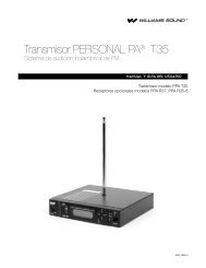
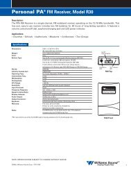
DECIDING BETWEEN COMPRESS OR LIMIT SETTINGS<br />
It’s easy to select Compress or Limit using one position of the Audio Select Switch. When<br />
choosing which mode to use, the system operator should consider the expected audience and<br />
program material. Figure 8 shows response curves for the compressor/limiter circuitry.<br />
A hearing impaired person’s perception of what is “too loud” is usually similar to a normal<br />
hearing person’s. However, they often don’t hear soft sounds as well. In other words, their<br />
dynamic range is reduced. To compensate, the T4’s Audio Processor can compress the audio<br />
signal, reducing the dynamic range and making it more useful to the hearing impaired.<br />
Some hearing impaired people cannot tolerate as loud a sound as those with normal hearing.<br />
When accompanied with hearing loss, their dynamic range is significantly reduced, both for<br />
soft and for loud sounds. Compression is especially useful for these individuals.<br />
In some situations, however, such as concerts, compression is annoying to listeners<br />
—especially musical purists. Limiting provides control of the modulation level and is<br />
optimized to cause a minimum of disturbance to the sound. It’s acceptable to the most<br />
discerning listeners, but not as helpful to hearing impaired people as compression.<br />
FIGURE 8: T4 AUDIO PROCESSOR PERFORMANCE<br />
+10<br />
0<br />
Hard Limiter (Always Functional)<br />
RELATIVE OUTPUT LEVEL<br />
–10<br />
–20<br />
Compress<br />
Limit<br />
–30<br />
Audio "-12 dB" Light ON<br />
Audio "0 dB" Light ON<br />
–40<br />
–40<br />
–30<br />
–20 –10<br />
0<br />
RELATIVE INPUT LEVEL<br />
+10 +20<br />
<strong>Williams</strong> <strong>Sound</strong> ®<br />
Helping People Hear<br />
15
STEP 5:<br />
CONNECT THE POWER SUPPLY<br />
The T4 transmitter is powered by a wall mounted transformer supplying 24 VAC. Plug the<br />
transformer into a suitable 120 VAC outlet and connect the attached cable to the transmitter.<br />
The cable connector has a retaining catch which must be installed toward the top of the<br />
transmitter as shown on the T4’s back panel. Though no damage will result, the T4 will not<br />
operate if you install the cable upside down.<br />
Neither the T4, nor its power supply, are equipped with a power switch. Because there is no<br />
“wear out” mechanism and power consumption is minimal, continuous operation is not a<br />
problem. If you want to control power to the transmitter, connect the power transformer to a<br />
switched 120 VAC supply or a master switched outlet for the entire sound system.<br />
STEP 6:<br />
ADJUST THE AUDIO INPUT CONTROL<br />
Play a compact disc or other quality audio source through the complete sound system at a<br />
level that is typical of normal operation. Adjust the Audio Input control so that the Level<br />
Indicator 0 dB LED generally lights and the +6 dB LED lights occasionally.<br />
16<br />
<strong>Williams</strong> <strong>Sound</strong> ®<br />
Helping People Hear
ASSURING EXCELLENT PERFORMANCE<br />
The PPA 275 consists of a transmitter and several receivers used to deliver an audio signal to<br />
listeners who are hard of hearing. The audio signal is usually provided by equipment<br />
manufactured and installed by others. The PPA 275 provides excellent audio performance<br />
under most conditions. However, <strong>Williams</strong> <strong>Sound</strong> equipment does not correct faults in<br />
incoming audio. This section is intended to help installers and users recognize proper<br />
operation and correct faults whenever possible.<br />
The following tests can be done without instruments to assure that a system is working<br />
properly.<br />
HOW TO RECOGNIZE PROPER OPERATION<br />
Step 1: Play a compact disc through the complete sound system at a level that is typical of<br />
normal operation. Listen to the hearing assistance system using a receiver with a<br />
factory-supplied earphone. Set the volume on the receiver at about 3. Comfortable<br />
listening is usually achieved with a setting of 2, or even lower. If you have normal<br />
hearing, a volume control setting of 3 will likely be too loud for comfortable<br />
listening. There should be no audible distortion, hum or noise.<br />
<strong>Williams</strong> <strong>Sound</strong> wide-band FM systems transmit audio using the same technical<br />
standards as FM Broadcast radio. Therefore, the received sound should be of high<br />
quality. Using a suitable adapter (Radio Shack Part #274-361), you can connect a<br />
professional headphone to a receiver for a critical evaluation.<br />
Step 2: Pause or stop the CD.<br />
There should be no significant increase in noise or hum immediately after the<br />
sound is stopped.<br />
Step 3: Play the CD again.<br />
Listen to the system using a receiver. Check for coverage in the listening area.<br />
Walk through and around the entire audience area. The sound in the receiver<br />
should remain clear and noise–free within the audience area.<br />
Some small spots in the listening area will seem to “dropout,” getting no signal.<br />
This is normal and is caused by RF signal reflections from relatively large<br />
electrically conductive objects. In most installations, the areas of reduced reception<br />
are less than one foot wide and few in number. Moving the receiver only a few<br />
inches usually restores reception.<br />
<strong>Williams</strong> <strong>Sound</strong> ®<br />
Helping People Hear<br />
17
RECEIVER USE INSTRUCTIONS<br />
RECEIVER MODEL PPA R30<br />
Receiver Model PPA R30 has a single, wheel-type volume control and an earphone output jack.<br />
BATTERY INSTALLATION<br />
Open the battery compartment using a coin in the slot in the bottom of the receiver. Press the<br />
batteries into place, observing proper battery polarity. Incorrect insertion of the batteries is<br />
difficult, and may cause both mechanical and electrical damage to the receiver not covered<br />
by the 5 year warranty. The receiver will not work with the batteries incorrectly installed.<br />
CONNECTING EARPHONES<br />
Plug an earphone into the jack near the thumb wheel volume control. Only monophonic<br />
earphones will operate properly. If stereo headphones are used, sound will be heard only in<br />
one side. A suitable adapter (Radio Shack Part #274-368), can be used so that stereo<br />
earphones operate on both sides. <strong>Williams</strong> <strong>Sound</strong> extensively evaluates the earphones and<br />
headphones included with the PPA 275. We can only assure optimum performance when<br />
<strong>Williams</strong> <strong>Sound</strong> earphones and headphones are used.<br />
OPERATING THE RECEIVER<br />
Turn the receiver on by rotating the volume control in the direction of the arrow on top of the<br />
case. The “On” indicator will light.<br />
Turning the knob in the direction of the arrow will increase the volume. Turning the knob<br />
against the arrow will decrease the volume. To avoid depleting the batteries, make sure the<br />
receiver is turned off when not in use.<br />
If you’re using the PPA 275 with an existing sound system, make sure the sound system is<br />
turned on. Have someone speak into a sound system microphone while you listen with the<br />
receiver and earphone. You should be able to hear their voice through the receiver.<br />
If you’re using the PPA 275 with a microphone—and not a complete sound system—have<br />
someone speak into the microphone while you listen with the receiver and earphone. You<br />
should be able to hear their voice through the receiver.<br />
Note:<br />
The earphone cord is the receiving antenna. Do not bunch up the cord or wrap it<br />
around the receiver, while in use.<br />
ADDITIONAL RECEIVER INSTRUCTIONS<br />
MODELS PPA R7-4 AND PPA R7-6<br />
The R7-4 and R7-6 receivers feature a channel selector knob on top of the receiver. Turn the<br />
selector knob until you hear the desired program.<br />
MODEL PFM R16:<br />
The R16 Receiver features an environmental microphone input and dual volume controls.<br />
The taller knob turns the receiver on and off and controls the transmitted signal level. The<br />
18<br />
<strong>Williams</strong> <strong>Sound</strong> ®<br />
Helping People Hear
shorter knob controls the microphone signal level. By adjusting the two volume controls, you<br />
can hear a mixture of the transmitted signal and nearby sounds.<br />
Note:<br />
Some users may not be helped by this system. Severe hearing loss may require<br />
using the system with a telecoil coupler (i.e., Neckloop) and personal hearing aid.<br />
USING A RECEIVER WITH A HEARING AID<br />
<strong>Williams</strong> <strong>Sound</strong> PPA Receivers can be used with hearing aids using three different methods:<br />
NECKLOOP TELECOIL COUPLER<br />
Neckloops are cords which hang around the neck and couple magnetically with T-Coil<br />
equipped hearing aids.<br />
SILHOUETTE TELECOIL COUPLER<br />
These telecoil couplers are worn behind the ear, right next to telecoil-equipped hearing aids.<br />
DIRECT AUDIO INPUT (DAI) CORD<br />
Direct Audio Input cords can be used with compatible hearing aids as well as with Cochlear<br />
Implant Processors.<br />
<strong>Williams</strong> <strong>Sound</strong> ®<br />
Helping People Hear<br />
19
BATTERY INFORMATION<br />
DISPOSABLE BATTERIES<br />
In normal use, two AA 1.5 V non-rechargeable Alkaline batteries will last about 80 hours. If<br />
the sound becomes weak or distorted, replace the battery. The indicator light may still be on,<br />
even with a battery that is weak. Do not leave dead batteries in the receivers. Battery<br />
corrosion is not covered by the <strong>Williams</strong> <strong>Sound</strong> five year warranty.<br />
RECHARGEABLE BATTERIES<br />
The R30 can also use two AA 1.5 V Ni-Cad rechargeable batteries (BAT 026). Two fully<br />
charged BAT 026’s will provide up to 50 hours of use. Damage from improper charging is<br />
not covered by the <strong>Williams</strong> <strong>Sound</strong> five year warranty.<br />
The batteries installed in the receiver may be recharged in the receiver only if they are<br />
Nickel Cadmium batteries, and only if the correct <strong>Williams</strong> <strong>Sound</strong> charger is used.<br />
Recharge batteries only with a <strong>Williams</strong> <strong>Sound</strong> CHG 200A 3V Dual Multi Charger or the<br />
CHG 1600 Multiple Battery Charger. Make sure the receiver is turned off during charging. A<br />
complete recharge cycle takes about 14 hours. Receivers should not be left charging<br />
continuously when not in use.<br />
!! IMPORTANT WARNINGS !!<br />
DO NOT ATTEMPT TO RECHARGE ZINC CARBON (“HEAVY DUTY”), ALKALINE, OR<br />
LITHIUM BATTERIES!<br />
DO NOT ATTEMPT TO RECHARGE DISPOSABLE BATTERIES! These batteries may heat up<br />
and explode, causing possible injury and damage to the equipment.<br />
Avoid shorting the plus and minus battery terminals together with metal objects. Battery<br />
damage and burns can result!<br />
Use only <strong>Williams</strong> <strong>Sound</strong> supplied chargers and batteries!<br />
20<br />
<strong>Williams</strong> <strong>Sound</strong> ®<br />
Helping People Hear
FREQUENCY CHANGE INSTRUCTIONS<br />
Normally, the PPA 275’s factory-set channel (usually 72.9 MHz) requires no change.<br />
However, if another hearing assistance system or authorized radio service is operating on<br />
72.9 MHz in your area, it may prove necessary to use an alternate channel.<br />
In this event, the PPA System 275’s operating frequency can easily be changed to an alternate<br />
channel to avoid interference.<br />
See the following sections for instructions on changing frequencies.<br />
TRANSMITTER FREQUENCY CHANGE PROCEDURE:<br />
Set the T4 Transmitter to any of the 10 available channels using the FM Channel/FM Power<br />
Switch. See figure 9.<br />
IMPORTANT: Some cities have other radio services licensed on hearing assistance<br />
channels. Under FCC rules governing hearing assistance, you must yield to<br />
them. A list of cities where other radio services are known to exist is<br />
included with the transmitter. Do not use frequencies that are known to be<br />
used by licensed radio services in your city, either if they are on the list or if<br />
you discover one.<br />
Figure 9: FM Channel/FM Power Switch Settings<br />
RF CONFIG SWITCH<br />
SWITCH SETTINGS<br />
1 2 3 4 5<br />
FREQUENCY<br />
72.100 MHz ON ON ON ON OFF<br />
72.300 MHz ON ON OFF ON OFF<br />
72.500 MHz ON OFF ON ON OFF<br />
72.700 MHz ON OFF OFF ON OFF<br />
72.900 MHz OFF ON ON ON OFF<br />
74.700 MHz OFF ON OFF OFF ON<br />
75.300 MHz ON ON ON OFF OFF<br />
75.500 MHz ON ON OFF OFF OFF<br />
75.700 MHz ON OFF ON OFF OFF<br />
75.900 MHz ON OFF OFF OFF OFF<br />
RF OUTPUT POWER<br />
FULL<br />
HALF<br />
QUARTER<br />
OFF<br />
6 7 8<br />
OFF OFF<br />
OFF<br />
ON<br />
ON<br />
OFF<br />
ON ON<br />
Switches 1-5 toggles control<br />
frequency settings<br />
Switch 6 is not used<br />
Switches 7 and 8 control RF output<br />
power. The factory setting is FULL, and<br />
can be adjusted if conditions warrant.<br />
See Troubleshooting <strong>Guide</strong>.<br />
Remember: If you change the<br />
transmitter frequency, you must also<br />
change receiver frequencies.<br />
“On” and “Off” are labeled on the<br />
body of the DIP switches.<br />
<strong>Williams</strong> <strong>Sound</strong> ®<br />
Helping People Hear<br />
21
RECEIVER FREQUENCY CHANGE INSTRUCTIONS<br />
Tuning for the R7, R30, R31, and R32 receivers is determined by a single tuning coil. In the<br />
R7-4 and R7-6, one coil is assigned to each switch position. See the following 6 figures and<br />
receiver types to locate the coils to be adjusted. A plastic tuning wrench (PLT 005) will be<br />
needed to adjust these receiver tuning coils.<br />
1<br />
2<br />
1 2<br />
IC01<br />
TUNING COIL<br />
R30 R-31 R-32<br />
Ferrite Tuning<br />
"Slug"<br />
1<br />
2<br />
3<br />
4<br />
R7Y R7-4 R7-6<br />
5<br />
6<br />
1<br />
2<br />
3<br />
4<br />
Most <strong>Williams</strong> <strong>Sound</strong> single channel Receivers are set at the factory to 72.9 MHz. The<br />
standard four-channel receivers (R7-4NA), Channels 1-4, are usually set to frequencies 72.1,<br />
72.5, 72.9, 75.7 MHz respectively. The standard six-channel receivers (R7-6N), channels 1-<br />
6, are set to frequencies 72.1, 72.5, 72.9, 75.7, 74.7 and 75.3 MHz respectively.<br />
The Receiver must be tuned with a weak and somewhat noisy signal. If tuned too close<br />
to the transmitter, with a strong signal, the most accurate tuning of the receiver is not<br />
possible.<br />
To Change the Frequency to Another Channel:<br />
Step 1:<br />
Step 2:<br />
Step 3:<br />
Step 4:<br />
Set the transmitter to the channel desired and remove the antenna.<br />
Connect an audio source to the transmitter such as a CD or cassette player or<br />
microphone.<br />
Move the receiver about 25 feet away from the transmitter to set the tuning.<br />
Open the battery compartment, then lift up on the battery door to open the back<br />
of the receiver. This will expose the tuning coil or coils to be adjusted.<br />
22<br />
<strong>Williams</strong> <strong>Sound</strong> ®<br />
Helping People Hear
Step 5:<br />
Step 6:<br />
Step 7:<br />
Step 8:<br />
Step 9:<br />
Locate the Tuning Coil. (See figure on previous page). Each tuning coil is a<br />
small, square, shiny metal can with a screwdriver slot in a tuning slug in the top<br />
center. The Tuning Slug is usually black or gray.<br />
With the earphone or headphone supplied with the receiver plugged into the Ear<br />
Jack, turn the volume control to a comfortable level, and listen for the transmitted<br />
signal.<br />
Gently put the tip of the tuning wrench into the slot in the tuning slug. Be careful<br />
not to push hard on the slug so as not to damage the threads in the coil, and do<br />
not screw it down more than 3 turns into the coil.<br />
Turn the tuning slug in a counter-clockwise direction about two turns. Then,<br />
slowly turn the tuning slug in the clockwise direction until the signal is heard.<br />
There may be two signal points heard. The one which is received first is a false<br />
response. Be sure to continue tuning slightly further to the correct point, which<br />
will be much louder. Tune back and forth to find the center of the point of best<br />
response to the program being heard.<br />
Mark down the date, and if a new frequency has been chosen, mark it down<br />
inside the receiver case for future reference.<br />
SUGGESTIONS FOR RECEIVER MANAGEMENT<br />
Different types of facilities use varying approaches to receiver management and earphone<br />
sanitation. Below are some options that customers have used successfully.<br />
1. Regular users purchase or are given their own receiver and take care of their own<br />
batteries and earphones.<br />
2. The facility labels a receiver and earphone for each regular user. The facility<br />
maintains the units.<br />
3. Ushers issue receivers to people who request them.<br />
Earphones are sanitized after use. Foam ear cushions can be replaced or washed<br />
with a mild detergent, rinsed thoroughly and air-dried. The EAR 022 Surround<br />
Earphone can be sanitized with an alcohol pad.<br />
The receivers can be stored in a multiple compartment storage case with a credit<br />
card or driver’s license left as collateral for the receiver.<br />
4. Regular users purchase their own earphone or headphone and bring them to use<br />
with receivers at the facility.<br />
<strong>Williams</strong> <strong>Sound</strong> ®<br />
Helping People Hear<br />
23
TROUBLE SHOOTING GUIDE<br />
NO TRANSMITTER OPERATION<br />
POWER LIGHT NOT ON<br />
<br />
Most likely, there is no power. Make sure the power outlet is working and that the PPA<br />
275’s power supply (TFP 016) is connected correctly.<br />
AUDIO DIFFICULTIES (AS HEARD IN PHONES JACK ON TRANSMITTER)<br />
NO AUDIO HEARD IN PHONES JACK<br />
<br />
Check to see if there is a signal coming from your audio source. Check and correct your<br />
audio source if necessary.<br />
<br />
<br />
Check to see if the Audio Level control has been turned all the way down. If so, adjust it.<br />
Check to see if there is an incorrect or defective connection from your audio source. See<br />
page 13-14 for detailed connection instructions.<br />
NOISE IN AUDIO<br />
<br />
Check to see if there is noise in source audio. To find out, disconnect the audio cable. If<br />
the noise disappears your noise problem is in the source. Correct or repair your audio<br />
source.<br />
<br />
Check to see if your source level is too low. If so, readjust your source audio level or<br />
reset Audio Select switch to match the existing source level.<br />
BUZZ OR HUM IN AUDIO<br />
<br />
Check to see if the buzz or hum is in the source. If so, correct or repair your audio<br />
source.<br />
<br />
Check to see if there is an incorrect or defective connection from source. If so, correct<br />
your connections. See page 13-14 for detailed instructions.<br />
DISTORTED AUDIO<br />
<br />
Check to see if the source audio is distorted source. If so, correct or repair your audio<br />
source.<br />
<br />
<br />
<br />
Perhaps the Audio Select switch is not set to match your audio source. If this is the case,<br />
reset the Audio Select switch to match and/or readjust the source.<br />
Check to see if the Audio Level control is set too high. If the +6 level indicator is on all<br />
the time, adjust the Level control counter–clockwise.<br />
If the Audio Level control is set near fully counter–clockwise, the Audio Select switch is<br />
set incorrectly. Set Audio Select switch to match your audio source and/or readjust the<br />
source.<br />
NOISE IN AUDIO “GROWS” WHEN PROGRAM IS SILENT<br />
<br />
The Audio Level control is set too high. You’re probably also seeing the +6 level<br />
indicator lighting all the time. To correct, adjust the Audio Level control.<br />
24<br />
<strong>Williams</strong> <strong>Sound</strong> ®<br />
Helping People Hear
It could be that the T4’s Audio Processor is set for Compress when Limit might be more<br />
appropriate for the type of program being transmitted. Reset the Audio Select switch for<br />
Limit. See page 15.<br />
RECEPTION (AT RECEIVER) DIFFICULTIES<br />
Check Audio Difficulties (as heard in phones jack on transmitter) before checking reception.<br />
NO RECEPTION<br />
<br />
If the T4’s RF Indicator LED is not on, it’s possible that an invalid channel is set on the<br />
FM Channel/FM Power Switch. Reset this switch to a valid channel.<br />
<br />
<br />
Check to see if the antenna has been disconnected. If so, attach the antenna correctly.<br />
Check to see if the output power is set to “OFF.” If so, reset the FM Channel/FM Power<br />
Switch for FULL, HALF, or QUARTER RF output.<br />
INSUFFICIENT RANGE, GOOD RECEPTION NEAR TRANSMITTER, POOR AT A DISTANCE<br />
<br />
Check to see if the transmitting antenna was installed incorrectly. If so, correct or replace<br />
the antenna. The signal should be clearly audible at a 300 foot distance with the<br />
ANT 021 and a 500 foot distance with the ANT 005.<br />
<br />
<br />
Make sure the transmitting antenna is not in an unsuitable location.<br />
Perhaps the transmitting antenna was installed inside a metal enclosure or is separated<br />
from the reception area by electrically conducting objects. (i.e., steel stud walls, heating<br />
ducts, substantial structural steel, or 2x2 or 2x4 ceiling grid.) In either case, reinstall the<br />
antenna according to installation instructions, locating it outside metal enclosures and<br />
away from electrically conducting objects.<br />
Perhaps there is a strong interfering signal. If so, make sure the transmitter and antenna<br />
are correctly installed. Set the transmitter to FULL power output. If this does not solve<br />
the problem, change the PPA 275’s frequency by setting the FM Channel/FM Power<br />
Switch according to the instructions on page 21.<br />
DROPOUTS: AREAS OF NO RECEPTION WITHIN NORMAL RECEPTION AREA<br />
<br />
If dropout areas are few and less than 2 feet across, there is no problem. This is part of<br />
normal operation.<br />
<br />
If dropouts are many and large, see the section on insufficient range above.<br />
POPS OR SIMILAR LARGE DEFECTS IN RECEIVED AUDIO<br />
<br />
Check to see if there is defective audio at the transmitter. If so, See the Audio Difficulties<br />
section on page 24.<br />
<br />
<br />
Check to see if the receivers are incorrectly tuned. If so, adjust receiver according to<br />
instructions on page 22.<br />
Check to see if there is a strong interfering signal by listening to the receiver with the<br />
transmitter turned off. If an interfering signal is causing overload in the receivers, see the<br />
section on insufficient range above. If changing channels does not remedy the problem,<br />
<strong>Williams</strong> <strong>Sound</strong> ®<br />
Helping People Hear<br />
25
use other technology, such as <strong>Williams</strong> <strong>Sound</strong> Narrow Band FM or <strong>Williams</strong> <strong>Sound</strong><br />
Infrared.<br />
USERS MUST TURN RECEIVER VOLUME CONTROLS WAY UP (TO 4 OR 5) TO GET ENOUGH VOLUME<br />
Perhaps there is insufficient audio level. If so, the audio level indicator will read too low<br />
because the audio level is set incorrectly on the transmitter. Correct the Audio Level<br />
control setting.<br />
<br />
<br />
It could be that the input is not configured for the audio source used. If not, correct the<br />
setting of the Audio Select switch.<br />
Some users may not be helped by this system. Severe hearing loss may require using the<br />
system with a telecoil coupler (i.e., Neckloop) and personal hearing aid.<br />
USERS COMPLAIN OF NOT HEARING LOW LEVEL SOUNDS<br />
<br />
Check to see if the Audio Level is set too low. If so, adjust the Audio Level, carefully<br />
noting the Level Indicator. The +6 LED should light occasionally.<br />
<br />
Check to see if the transmitter is set for Limit when the program material would benefit<br />
from Compress mode. If so, set the Audio Select switch for Compress.<br />
USERS COMPLAIN OF TOO MUCH NOISE DURING SOFT AUDIO. DYNAMIC RANGE OF MUSIC REDUCED TOO<br />
GREATLY.<br />
<br />
Check to see if the Audio Level control is set too high. This problem is more likely to<br />
occur in Compress Mode, but can also occur in Limit Mode. To reduce this noise, adjust<br />
the Audio Level, carefully noting the Level Indicator. The +6 LED should light<br />
occasionally.<br />
<br />
Perhaps the transmitter is set for Compress when Limit Mode would be more suitable,<br />
given the program material. If so, set the Audio Select switch for Limit.<br />
BUZZ IN OTHER EQUIPMENT WHEN TRANSMITTER IS ON OR OFF<br />
<br />
This is not an RF problem. Instead, it is likely caused by incorrect audio connections, a<br />
ground loop, or defective equipment. To remedy, use proper audio wiring practice to<br />
make connections described on page 14.<br />
BUZZ OR OTHER NOISE IN EQUIPMENT ONLY WHEN TRANSMITTER IS ON<br />
<br />
This is likely an RF–induced disturbance in the other equipment. To remedy, try these<br />
steps in order until the buzz is eliminated:<br />
1. Make certain the transmitter chassis is connected to the equipment cabinet rails.<br />
2. Make sure antenna connections are secure.<br />
3. Set the T4 Transmitter to HALF or QUARTER power output using the<br />
FM Channel/FM Power Switch.<br />
4. Install transmitter at a distance from sensitive equipment.<br />
5. Use a remote antenna (ANT 005 or ANT 024).<br />
6. Make sensitive equipment more immune to RFI/EMI. The manufacturers of your<br />
audio equipment may offer application notes for this purpose. <strong>Williams</strong> <strong>Sound</strong> offers<br />
a document giving suggestions for improving RF immunity in existing audio<br />
equipment (Technical Bulletin: Buzz Or Hum In The <strong>Sound</strong> System, FRM 531).<br />
26<br />
<strong>Williams</strong> <strong>Sound</strong> ®<br />
Helping People Hear
WARRANTY<br />
The <strong>Williams</strong> <strong>Sound</strong> T4 Transmitter and R30 Receiver are engineered and<br />
designed to provide you with many years of reliable service. <strong>Williams</strong> <strong>Sound</strong><br />
warrants it against defects in materials and workmanship for FIVE (5) years<br />
EXCEPT FOR earphones, headphones, rechargeable batteries, chargers,<br />
cables, antennas, carry cases, and all other accessory products. Accessory<br />
products carry a 90 day warranty.<br />
If the product fails within the specified warranty period, <strong>Williams</strong> <strong>Sound</strong> will<br />
determine whether to repair or replace the defective equipment. This<br />
warranty does not apply to physical damage, abuse, mis-use, or products that<br />
have been modified.<br />
If you experience difficulty with your system, call for Customer Assistance:<br />
1-800-328-6190.<br />
If it is necessary to return the system for service, a <strong>Williams</strong> <strong>Sound</strong><br />
representative will give you a Return Authorization Number (RA) and<br />
shipping instructions. Pack the system carefully and send it to:<br />
<strong>Williams</strong> <strong>Sound</strong> Corp.<br />
10399 West 70th Street<br />
Eden Prairie, MN 55344-3459 USA<br />
Phone: 800-843-3544 / 952-943-2252<br />
Fax: 952-943-2174<br />
TTY: 952-943-9675<br />
e-mail: info@williamssound.com<br />
Your warranty becomes effective the date you purchase your system. Your<br />
returned warranty card is our way of knowing when your warranty begins. It<br />
also gives us important information about your system including the serial<br />
number. This information will help us serve you better in the future. Please<br />
take a moment to complete and mail the attached card. Thank you.<br />
<strong>Williams</strong> <strong>Sound</strong> ®<br />
Helping People Hear<br />
27
Pro Wide–band System, Model PPA 275 SPECIFICATIONS<br />
PERSONAL PA Transmitter Model T4<br />
Dimensions, Weight: 8.45" (21.5 cm) W x 8.18" (20.8 cm) D<br />
x 1.72" (4.4 cm) H, 3lbs. (1.5 kg)<br />
Color:<br />
Black epoxy paint with white legends<br />
Rack Mount:<br />
One EIA rack space high, 1/2 space wide<br />
1–2 units can be mounted in a single rack<br />
space with optional RPK 005 (single) or<br />
RPK 006 (double) Rack Mount Kits<br />
Power:<br />
21 VAC minimum; 26 VAC maximum,<br />
50 or 60 Hz 4.8 VA nominal; 10 VA maximum;<br />
Wall mount transformer for 105 to 130 VAC<br />
included<br />
FCC ID:<br />
CNMT4<br />
Operating Freqs: 72.1–75.9 MHz *<br />
10 wide–band channels, selectable<br />
Frequency Accuracy: ±.005% stability, 0-50˚ C<br />
Deviation:<br />
± 75 kHz maximum<br />
Pre-Emphasis:<br />
75 µsec<br />
RF Field Strength: Does not exceed 8 mV/m at 3 m<br />
Nominal Range: 300-500 ft. (90-150 m)<br />
Audio Proc. Functions: Soft Knee Limit or Compress<br />
Compression 10 dB add’l gain when input is –20 dB<br />
20 dB add’l gain when input is –40 dB<br />
Soft Limiting > 10 dB add’l gain when input is –45 dB<br />
Frequency Response: 30 – 16000 Hz, +1, -3 dB<br />
Signal to Noise Ratio: More than 70 dB below 75 kHz deviation<br />
in Limit mode<br />
Note:<br />
Maximum transmitter range is achieved<br />
using the ANT 005 coaxial antenna<br />
T4 Transmitter Front Panel<br />
PPA T4 Professional FM Auditory Assistance Transmitter<br />
Frequency Synthesized, Channel-Selectable<br />
Audio Adjust<br />
Audio Level<br />
Power -12dB -6dB 0dB +6dB<br />
RF Carrier<br />
<strong>Williams</strong> <strong>Sound</strong><br />
Phones<br />
Decrease<br />
Increase<br />
Lo<br />
Ok<br />
Ok<br />
Too Hi<br />
Power Indicator:<br />
Audio Level Control:<br />
Green LED<br />
Rotary pot, screwdriver adjust,<br />
used with audio level indicator lights<br />
Audio Level Indicators: 4 LED array, reads -12, -6, 0, and +6 dB<br />
RF Carrier On Indicator: Green LED indicates transmitter RF is on<br />
Phones Jack:<br />
1/4" TRS (Stereo) jack<br />
T4 Transmitter Rear Panel<br />
Audio Select<br />
Audio Input<br />
(XLR) Bal. Mic<br />
Bal./Unbal line or 70V<br />
(TRS) Bal./Unbal .<br />
Line or 70V<br />
Model PPA T4 Auditory Assistance FM Transmitter<br />
<strong>Williams</strong> <strong>Sound</strong> Corp., Minneapolis, MN USA<br />
Line Out<br />
FM Channel,<br />
Power<br />
Antenna<br />
Power: 24 VAC,<br />
50-60 Hz, 10VA<br />
1 2 3 4 5 6 7 8 1 2 3 4 5 6 7 8<br />
To configure, see chart on top.<br />
See chart on top.<br />
75 Ohms<br />
Plug<br />
Audio Select Switch: Eight–section DIP switch<br />
Audio Input:<br />
Combination 3-pin XLR, 1/4" TRS jack<br />
Line Output:<br />
RCA jack, 0.6 V output, impedance 1000 Ω<br />
FM Channel Switch: Eight–section DIP switch (Seven used)<br />
Antenna Outputs: Hard-wired 75 Ω Coaxial Antenna (ANT 005)<br />
uses RG-59 cable, 400 ft. (122 m) max.<br />
cable length<br />
PERSONAL PA Receiver, Model PPA R30<br />
Dimensions:<br />
3-5/8" L x 2-3/8" W x 7/8" H<br />
(92.1 mm x 60.3 mm x 22.2 mm)<br />
Weight:<br />
4.6 oz (130 g) with batteries<br />
Color:<br />
Gray<br />
Battery Type:<br />
Two (2) AA 1.5 V non-rechargeable Alkaline<br />
batteries (BAT 001), 14 mA nominal current drain, 80<br />
hours approx. life<br />
(OR)<br />
Two (2) AA 1.5 V Ni-Cad rechargeable batteries<br />
(BAT 026), 14 mA nominal current drain, 50 hours<br />
per charge approx., recharges in 14–16 hours, uses<br />
CHG 1600 Charger or CHG 200 Charger<br />
FCC ID:<br />
CNM R30<br />
Industry Canada Cert.: 13601021234<br />
Operating Freq.: Pre-Tuned, Adjustable, 72 MHz - 76 MHz *<br />
*Note: FCC Rules limit the use of the 72–79 MHz band to hearing<br />
assistance for the handicapped only.<br />
Power Connections: 3-pin Molex ® connector<br />
Input Levels Minimum Nominal Maximum<br />
Microphone 100 µV 1 mV 100 mV<br />
Bal or Unbal Line 10 mV 100 mV 10 V<br />
Bal or Unbal<br />
70 V speaker line 2.3 V 23 V 230 V<br />
IMPORTANT: If you choose to connect to 70 Volt Speaker line,<br />
be certain to set the Audio Select switch correctly. Severe<br />
damage will occur if you do not.<br />
Intermediate Freq.: 75 kHz<br />
FM Deviation:<br />
75 kHz<br />
De-Emphasis: 75 µS<br />
AFC Range:<br />
± 120 kHz<br />
Sensitivity:<br />
4 µV at 12 dB Sinad<br />
Input Overload:<br />
20 mV<br />
Frequency Response: 100 – 10 kHz, ± 3 dB<br />
Signal-to-Noise Ratio: 50 dB at 10 µV<br />
Receive Antenna: Integral with earphone/headphone cord<br />
Audio Output:<br />
35 mW, max. at 16 Ω<br />
Output Connector: 3.5 mm mono phone jack<br />
Earphone:<br />
Earbud-type with foam cushion, 3.5 mm plug, 32 Ω<br />
Warranty:<br />
Five Years, Parts and Labor.<br />
90 days on cords, earphones, headphones,<br />
batteries and other accessories<br />
Notes: The R30 Receiver can be field tuned to any of 10<br />
wideband channels using the PLT 005 Tuning Tool.<br />
Your Authorized <strong>Williams</strong> <strong>Sound</strong> Dealer Is:<br />
© 2000, <strong>Williams</strong> <strong>Sound</strong> Corp. MAN 103 A