Installation Guide & User Manual - Williams Sound
Installation Guide & User Manual - Williams Sound
Installation Guide & User Manual - Williams Sound
- No tags were found...

You also want an ePaper? Increase the reach of your titles
YUMPU automatically turns print PDFs into web optimized ePapers that Google loves.
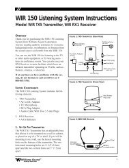
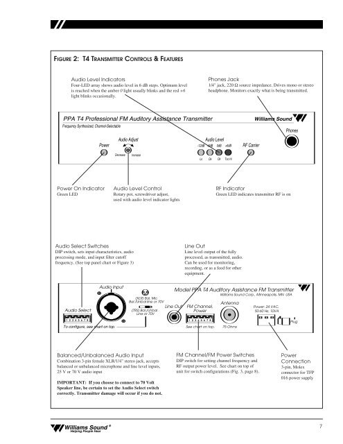
FIGURE 2: T4 TRANSMITTER CONTROLS & FEATURES<br />
Audio Level Indicators<br />
Four-LED array shows audio level in 6 dB steps. Optimum level<br />
is reached when the amber 0 light usually blinks and the red +6<br />
light blinks occasionally.<br />
Phones Jack<br />
1/4" jack, 220 Ω source impedance. Drives mono or stereo<br />
headphone. Monitors exactly what is being transmitted.<br />
PPA T4 Professional FM Auditory Assistance Transmitter<br />
Frequency Synthesized, Channel-Selectable<br />
Audio Adjust<br />
Audio Level<br />
Power -12dB -6dB 0dB +6dB<br />
RF Carrier<br />
<strong>Williams</strong> <strong>Sound</strong><br />
Phones<br />
Decrease<br />
Increase<br />
Lo<br />
Ok<br />
Ok<br />
Too Hi<br />
Power On Indicator<br />
Green LED<br />
Audio Level Control<br />
Rotary pot, screwdriver adjust,<br />
used with audio level indicator lights<br />
RF Indicator<br />
Green LED indicates transmitter RF is on<br />
Audio Select Switches<br />
DIP switch, sets input characteristics, audio<br />
processing mode, and input filter cutoff<br />
frequency. (See top panel chart or Figure 3)<br />
Line Out<br />
Line level output of the fully<br />
processed, as transmitted, audio.<br />
Can be used for monitoring,<br />
recording, or as a feed for other<br />
equipment.<br />
Audio Select<br />
Audio Input<br />
(XLR) Bal. Mic<br />
Bal./Unbal line or 70V<br />
(TRS) Bal./Unbal .<br />
Line or 70V<br />
Line Out<br />
Model PPA T4 Auditory Assistance FM Transmitter<br />
FM Channel,<br />
Power<br />
<strong>Williams</strong> <strong>Sound</strong> Corp., Minneapolis, MN USA<br />
Antenna<br />
Power: 24 VAC,<br />
50-60 Hz, 10VA<br />
1 2 3 4 5 6 7 8 1 2 3 4 5 6 7 8<br />
To configure, see chart on top.<br />
See chart on top.<br />
75 Ohms<br />
Plug<br />
Balanced/Unbalanced Audio Input<br />
Combination 3-pin female XLR/1/4" stereo jack, accepts<br />
balanced or unbalanced microphone and line level inputs,<br />
25 V or 70 V audio input<br />
IMPORTANT: If you choose to connect to 70 Volt<br />
Speaker line, be certain to set the Audio Select switch<br />
correctly. Transmitter damage will occur if you do not.<br />
FM Channel/FM Power Switches<br />
DIP switch for setting channel frequency and<br />
RF output power level. See chart on top of<br />
unit for switch configurations (Fig. 3, page 8).<br />
Power<br />
Connection<br />
3-pin, Molex<br />
connector for TFP<br />
016 power supply<br />
<strong>Williams</strong> <strong>Sound</strong> ®<br />
Helping People Hear<br />
7