Install Instructions - Williams Sound
Install Instructions - Williams Sound
Install Instructions - Williams Sound

Create successful ePaper yourself
Turn your PDF publications into a flip-book with our unique Google optimized e-Paper software.
<strong>Install</strong>ationGuide &UserManualPERSONAL PA ® Pro Wide–band System 250Wireless FM Listening SystemTransmitter Model T4Receiver Models R7, R7–4<strong>Williams</strong> <strong>Sound</strong> ®Helping People HearMAN 071 D
PRO WIDE–BAND SYSTEM, MODEL PPA 250INSTALLATION GUIDE & USER MANUALContentsPageFAST SET-UP PROCEDURE 4SYSTEM OVERVIEW 6CONTROLS AND CONNECTORS 8DETAILED SET-UP PROCEDURE 4MOUNTING THE TRANSMITTERINSTALLING THE ANTENNACHOOSING A CHANNELCHOOSING AND CONNECTING AN AUDIO SOURCECHOOSING AN AUDIO SOURCE FOR THE HEARING IMPAIREDCONNECTING THE POWER SUPPLYADJUSTING THE AUDIO INPUT CONTROLAUDIO PROCESSOR OPTIONS 16ASSURING EXCELLENT PERFORMANCE 17RECEIVER USE INSTRUCTIONS 18BATTERY INFORMATION 19RADIO INTERFERENCE TUNING INSTRUCTIONS 20SUGGESTIONS FOR RECEIVER MANAGEMENT 21TROUBLE SHOOTING GUIDE 22WARRANTY 25SYSTEM SPECIFICATIONS 26<strong>Williams</strong> <strong>Sound</strong> ®Helping People Hear3
FAST SETUP PROCEDUREStep 1Choose a Location for the TransmitterIt’s usually most convenient to locate the T4 next to the public address equipment. Thelocation must have the audio feed and 120 VAC power available. Place the transmitter on alevel surface where there are no substantial metal or other electrically conductive objectsbetween the antenna and the listening area.After initial adjustments, there should be no need to access the unit.Step 2Choose a Location and <strong>Install</strong> the AntennaThe T4 is equipped with a with a short flexible antenna (ANT 021). The ANT 021 threadsonto a stud recessed in a hole on the top of the transmitter. Do not use excessive force totighten the antenna; it need only be finger tight.The T4 Transmitter can also be purchased with a with a coaxial antenna (ANT 005) or WallMount Dipole Antenna (ANT 024).See Remote Antenna Location Tips on page 11 for more detail.Step 3Choose a ChannelBoth the T4 Transmitter and R7 Receivers are set to 72.9 MHz at the factory, unlessotherwise specified. However, you may easily set the T4 to any of the 10 available channelsusing the FM Channel/FM Power Switch. You may wish to use a different channel if there isalready another hearing assistance system or operations by some other authorized radioservice operating on 72.9 MHz in your area.Receivers must also be set to the same frequency. See page 20 for receiver tuninginstructions.Step 4Choose and Connect an Audio SourcePlug the T4’s audio cable into either Line Out, Record Out, Tape Out or Auxiliary Out jackon your system amplifier. If these outputs are already in use, a simple Y–cord can be used tomake the connection. Plug the other end of the audio cable into the T4’s Audio Input Jack onthe rear panel. If all line level outputs are in use, the T4’s line out jack on the transmitter’srear panel can be used to feed other devices.IMPORTANT: If you choose to connect to 70 Volt Speaker line, be certain to set theAudio Config switch correctly. Severe damage will occur if you do not.4<strong>Williams</strong> <strong>Sound</strong> ®Helping People Hear
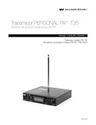
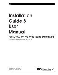
Frequency Synthesized, Channel-SelectableDecreaseIncreaseLoOkOk Too HiSYSTEM OVERVIEWThe PPA 250 is a Wide-band FM Listening System which operates in the 72–76 MHzfrequency band.Developed for hearing assistance in places of public access, the PPA 250 is designed forthose who need help overcoming background noise, reverberation, or distance from thesound source. It includes a complete audio processor optimized for the needs of hearingimpaired persons and is easily integrated with your existing sound system. The PPA 250 canalso be used with a microphone as a stand-alone system.Your PPA 250 has two principal parts: the T4 Transmitter and the R7 Receivers. Much like aminiature radio station, the transmitter and microphone pick up the sounds you want to hearand broadcast them over an FM radio signal. The receivers pick up the broadcast up to 500feet away.Listeners may sit anywhere and can make the audio signal as loud as they wish withoutcausing PA system feedback or disturbing others.To avoid difficulties, read through this manual as you begin to use the system. Then save itfor questions that arise as you continue to use your PPA system.If you have any problems with this <strong>Williams</strong> <strong>Sound</strong> product, don’t hesitate to call us toll-freeat 1-800-843-3544.FIGURE 1: OVERALL SYSTEM DIAGRAMMicrophonesLoudspeakersLine-LevelOutput<strong>Sound</strong> System AmplifierLine-LevelInputPPA T4 Professional FM Auditory Assistance TransmitterAudio AdjustAudio LevelPower -12dB -6dB 0dB +6dBRF Carrier<strong>Williams</strong> <strong>Sound</strong>T4 TransmitterPhonesR7 / R7-4 Receiversw/Earphones6<strong>Williams</strong> <strong>Sound</strong> ®Helping People Hear
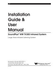
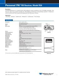
FIGURE 2: T4 TRANSMITTER CONTROLS & FEATURESAudio Level IndicatorsFour-LED array shows audio level in 6 dB steps. Optimum levelis reached when the amber 0 light usually blinks and the red +6light blinks occasionally.Phones Jack1/4" jack, 220 Ω source impedance. Drives mono or stereoheadphone. Monitors exactly what is being transmitted.PPA T4 Professional FM Auditory Assistance TransmitterFrequency Synthesized, Channel-SelectableAudio AdjustAudio LevelPower -12dB -6dB 0dB +6dBRF Carrier<strong>Williams</strong> <strong>Sound</strong>PhonesDecreaseIncreaseLoOkOkToo HiPower IndicatorGreen LEDAudio Level ControlRotary pot, screwdriver adjust,used with audio indicator lightsRF IndicatorGreen LED indicates transmitter RF is onAudio Select SwitchesDIP switch, sets input characteristics, audioprocessing mode, and input filter cutofffrequency. (See top panel chart or Figure 3)Line OutLine level output of the fullyprocessed, as transmitted, audio.Can be used for monitoring,recording, or as a feed for otherequipment.Audio SelectAudio Input(XLR) Bal. MicBal./Unbal line or 70V(TRS) Bal./Unbal .Line or 70VLine OutModel PPA T4 Auditory Assistance FM TransmitterFM Channel,Power<strong>Williams</strong> <strong>Sound</strong> Corp., Minneapolis, MN USAAntennaPower: 24 VAC,50-60 Hz, 10VA1 2 3 4 5 6 7 8 1 2 3 4 5 6 7 8To configure, see chart on top.See chart on top.75 OhmsPlugBalanced/Unbalanced Audio InputCombination 3-pin female XLR/1/4" stereo jack, acceptsbalanced or unbalanced microphone and line level inputs,25 V or 70 V audio inputIMPORTANT: If you choose to connect to 70 VoltSpeaker line, be certain to set the Audio Config switchcorrectly. Severe damage will occur if you do not.FM Channel/FM Power SwitchesDIP switch for setting channel frequency andRF output power level. See chart on top ofunit for switch configurations.PowerConnection3-pin, Molexconnector for TFP016 power supply<strong>Williams</strong> <strong>Sound</strong> ®Helping People Hear7
CONTROLS AND CONNECTORSFRONT PANELPOWER INDICATORIndicates that the transmitter has power available and that the unit is on.AUDIO ADJUST CONTROLControls level of audio signal and is connected between the input amplifier and the audiolevel processing circuit.AUDIO LEVEL INDICATORA four-LED array shows audio level in 6 dB steps. Indicator is average responding and iscalibrated so that optimum level is reached when the amber 0 light usually blinks and the red+6 light blinks occasionally.RF CARRIER INDICATORThe RF Carrier On Indicator shows when the transmitter is actually transmitting.PHONES JACKThe Phones Jack monitors the processed, “as transmitted” audio. It accommodates standardprofessional headphones with a 1/4" inch Tip-Ring-Sleeve (Stereo) plug. It can accept anyother type of headphone or earphone including those with Tip-Sleeve (Mono) plugs.Earphones with 3.5 mm plugs can be used with a suitable adapter (i.e., Radio Shack Part#274-367). Listening to this signal gives an accurate indication of the audio actually heard byusers.REAR PANELAUDIO SELECT SWITCHInput characteristics, audio processing mode, and input filter cutoff frequency are set by thisDIP switch. A chart of settings is shown in Figure 3 and on the top of the unit. “On” and“Off” are labeled on the body of the DIP switches.Figure 3: Audio Select Switch SettingsAUDIO CONFIG SWITCHAUDIO PROCESSORHI PASS FILTERAUDIO INPUT3 PINMICMIC W/SIMPLEXBAL/UNBAL LINEBAL/UNBAL 70 VLIMITCOMPRESSFLAT– 3 dB AT 200 Hz– 3 dB AT 730 HzTRS PHONEBAL/UNBAL LINEBAL/UNBAL LINEBAL/UNBAL LINEBAL/UNBAL 70 VSWITCH SETTINGS1 2 3 4 5 6 7 8ONOFFOFF OFFON OFFOFF ONOFF OFF ON ON ONONOFFONOFFONONONONONOFFOFF OFF OFF OFF OFFSwitch 1 selects between Limitand Compress ModesSwitches 2 and 3 control theHi Pass FilterSwitches 4-8 must be matchedto your audio inputSee page 13 for plug wiring diagrams.8<strong>Williams</strong> <strong>Sound</strong> ®Helping People Hear
INPUTThe input can be configured to accept three types of signal sources: Balanced or UnbalancedMicrophone, Balanced or Unbalanced Line, and 70 V speaker line. The input is configured toaccept various combinations of these inputs by means of the Audio Select switch. (SeeFigure 3.)PROFESSIONAL MICROPHONEMost dynamic, ribbon, or condenser microphones equipped with a balanced output and a3-pin XLR connector can be used. Power can be supplied for condenser microphonesaccording to DIN 45596. It can be turned off for dynamic and ribbon mics, though this is notusually required. Microphones are connected in the normal industry standard pinarrangement. The “in phase” signal conductor is connected to pin 2, the “out of phase” signalconductor is connected to pin 3, and the shield is connected to pin 1 of the XLR connector.Optimum performance is attained with 200 Ω microphones.LOW COST MICROPHONEMost low cost dynamic or condenser (with an internal battery) microphones equipped with atwo conductor 1/4" plug can be connected if an appropriate adapter is used. A suitableadapter is Radio Shack ® part number 274-017.BALANCED LINEAny balanced line level source can be connected to the 1/4" jack or the 3-pin XLR input. TheAudio Select switch must be set properly. The “in phase” signal conductor is connected tothe Tip of the 1/4" jack or to pin 2 of the XLR connector. The “out of phase” signalconductor is connected to the Ring of the 1/4" jack or to pin 3 of the XLR connector. Theshield is connected to the sleeve of the 1/4" jack or to pin 1 of the XLR connector. The inputimpedance is approximately 20 KΩ and performance is improved with a low sourceimpedance. With most professional audio equipment , connecting the input directly to a linelevel output is best.UNBALANCED LINEAny unbalanced line level source can be connected to the 1/4" jack or the 3-pin XLR input.The Audio Select switch must be set properly. The “hot” conductor is connected to the Tip ofthe 1/4" jack or to pin 2 of the XLR connector. The shield is connected to the sleeve of the1/4" jack or to pins 1 and 3 of the XLR connector. If a Tip-Ring-Sleeve 1/4" jack is used, theRing must be connected to the Sleeve. Input impedance is approximately 20 KΩ.Performance is improved with a low source impedance. With most professional audioequipment , connecting the input directly to a line level output is best.2 TO 16 Ω OR 70 V SPEAKER LINEThe T4 input can also be connected directly to 2 to 16 Ω or 70 Volt speaker lines.IMPORTANT: If you choose to connect to 70 Volt Speaker line, be certain to set theAudio Select switch correctly. Severe damage will occur if you do not.When making such connections, it’s very important to avoid creating ground loops. Pin 1 ofthe 3-pin connector and the sleeve of the 1/4" jack are connected directly to the chassis.Normally, one of these would be connected to the common output terminal of the poweramplifier connected to the speaker line. But in most installations, there cannot be an externalconnection from the common terminal of a power amplifier to ground. To avoid this<strong>Williams</strong> <strong>Sound</strong> ®Helping People Hear9
unacceptable situation, use a connection scheme like those described in the section AvoidingGround Loops.Set the Audio Select Switch for Line input when connecting to 2-16 Ω speakers. Set theAudio Select Switch for 70 V when connecting to 25 V or 70 V speaker lines.Speaker lines are most often equalized, making them an inferior signal source. Source signalsshould not be equalized.TAPE OUTPUTA line level output of the fully processed, “as transmitted” audio is provided through thisjack. Use it for monitoring audio quality, providing a processed signal for recording, or forother uses.FM CHANNEL/FM POWER SWITCHThe channel frequency and RF output power level are set according to a chart shown inFigure 4 as well as on the top of the unit. “On” and “Off” are labeled on the body of the DIPswitches. 10 wide band FM frequencies are available.Once the FM Channel/FM Power Switch is set, no further adjustment is required. RF outputcan be reduced to alleviate problems caused by inadequate immunity to RF in some audioequipment. <strong>Williams</strong> <strong>Sound</strong> offers a document (Technical Bulletin: Buzz Or Hum In The<strong>Sound</strong> System, FRM 531) giving suggestions for improving RF immunity in existing audioequipment.Figure 4: FM Channel Switch SettingsRF CONFIG SWITCHSWITCH SETTINGS1 2 3 4 5FREQUENCY72.100 MHz ON ON ON ON OFF72.300 MHz ON ON OFF ON OFF72.500 MHz ON OFF ON ON OFF72.700 MHz ON OFF OFF ON OFF72.900 MHz OFF ON ON ON OFF74.700 MHz OFF ON OFF OFF ON75.300 MHz ON ON ON OFF OFF75.500 MHz ON ON OFF OFF OFF75.700 MHz ON OFF ON OFF OFF75.900 MHz ON OFF OFF OFF OFFRF OUTPUT POWERFULLHALFQUARTEROFF6 7 8OFF OFFOFFONONOFFON ONSwitches 1-5 toggles controlfrequency settingsSwitch 6 is not usedSwitches 7 and 8 control RF outputpower. The factory setting is FULL, andcan be adjusted if conditions warrant.See Troubleshooting Guide.Remember: If you change thetransmitter frequency, you must alsochange receiver frequencies.POWER IN21 VAC to 26 VAC only, 50 or 60 Hz (TFP 016 Power Supply included with system).Current consumption is approximately 200 mA. One side of power input is connecteddirectly to circuit common (Chassis).10<strong>Williams</strong> <strong>Sound</strong> ®Helping People Hear
DETAILED SETUP PROCEDURESTEP 1:CHOOSE A LOCATION AND INSTALL THE TRANSMITTERIt’s usually most convenient to locate the T4 next to the public address equipment becauseyour transmitter location must have the audio feed and 120 VAC power available.FOR SIMPLE INSTALLATIONSPlace the transmitter on a level surface where there are no substantial metal or otherelectrically conductive objects between the antenna and the listening area. After initialadjustments, there will be no need to access the unit.FOR ENGINEERED INSTALLATIONSThe transmitter can be mounted in an equipment rack. Use a <strong>Williams</strong> <strong>Sound</strong> rack mount kit(RPK 005 or RPK 006). Make sure there is good electrical contact between the transmitterchassis and the rack cabinet.Ambient temperature of the transmitter location must not exceed 125° F.STEP 2:CHOOSE A LOCATION AND INSTALL THE ANTENNAThe T4 is equipped with a with a short flexible antenna (ANT 021). The ANT 021 threadsonto a stud recessed in a hole on the top of the transmitter. Do not use excessive force totighten the antenna; it need only be finger tight.The T4 can also be purchased with a coaxial antenna (ANT 005) or Wall Mount DipoleAntenna (ANT 024).REMOTE ANTENNA LOCATION TIPS<strong>Install</strong> the ANT 005 or ANT 024 with its elements vertical. It should be near or withinthe listening area and somewhat above the seats. However, do not install the antennadirectly overhead. There is a null in the coverage area off the ends of the antenna.The antenna is best installed on a wall 10 to 15 feet above the floor. It may be located inthe next room from the listening area if the separating wall does not contain metal lath,steel studs, or significant ductwork. Do not install the antenna in an organ chamber. Thenumerous pipes of an organ significantly deflect and absorb the radio signal.The ANT 005 and ANT 024 feedline is classified under the National Electrical Code asClass II wiring and may be installed in conduit with other Class II wiring. It SHOULDNOT be installed with Class I (power) wiring.Even though regulations allow the feedline to be installed with other audio systemwiring, you might still choose not to do this. Because all coaxial cable leaks to somedegree, other improperly shielded audio equipment might be interfered with. In thesecases, either avoid such installation or take steps as outlined in <strong>Williams</strong> <strong>Sound</strong>’sTechnical Bulletin: Buzz Or Hum In The <strong>Sound</strong> System (FRM 531). Other audioequipment will not disturb the transmitter or its antenna.Do not connect the coaxial cable to the building or electrical ground in any way.<strong>Williams</strong> <strong>Sound</strong> ®Helping People Hear11
AVOIDING UNDESIRABLE ANTENNA INSTALLATIONSTransmission (range, directional properties) can be severely impaired by improperinstallation of the antenna.DO NOT install the antenna within any metal enclosure.DO NOT install the antenna where it is within about 4 feet of any metal object that ismore than about 2 feet long.DO NOT install the antenna where it is separated from the listening area by anysubstantial metal object, such as heating ducts, structural steel, foil backed insulation,steel studs or metal lath.DO NOT install the antenna with its elements horizontal. It is a technical advantage touse vertical polarization as well as an FCC requirement.STEP 3:CHOOSE A CHANNELNormally, the T4’s factory-set channel (72.9 MHz) requires no change. However, it mayprove necessary to use an alternate channel if another hearing assistance system or authorizedradio service is operating on 72.9 MHz in your area.In this case, you may easily set the T4 Transmitter to any of the 10 available channels usingthe FM Channel/Power Switch. Remember, receivers must also be set to the same frequency.See page 20 for receiver tuning instructions.IMPORTANT: Some cities have other radio services licensed on hearing assistancechannels, and under FCC rules governing hearing assistance, you must yieldto them. A list is included with the transmitter of cities where other radioservices are known to exist. Do not use frequencies that are known to beused by licensed radio services in your city, either if they are on the list or ifyou discover one.NOTE:If you seem to be having interference problems, the best course of action isto first work through the Trouble Shooting Guide—in case the problem isnot caused by interference. Try retuning if the problem remains.FIGURE 5: USING THE AUDIO CABLE SUPPLIED FOR UNBALANCED CONNECTIONSFrom <strong>Sound</strong> SystemAmplifier's Line OutputTo T4 Audio InputRCA to RCA CableRCA to 1/4" Adapter12<strong>Williams</strong> <strong>Sound</strong> ®Helping People Hear
STEP 4:CHOOSE AND CONNECT AN AUDIO SOURCEYour choice of audio source can greatly affect the usefulness of your hearing assistancesystem.SIMPLE INSTALLATIONSIn simple sound systems, the best audio source is usually a Tape or Auxiliary output jack onthe system’s amplifier. Set the Audio Select switch for the type of source you have (SeeFigure 6.) and plug in a suitable audio cable. If those jacks are already in use, a simple “Ycord” can easily make the connection. See Figure 5 for use of the PPA 250’s audio cable.ENGINEERED INSTALLATIONSIn an engineered audio system, use good wiring practice to properly connect the audio feedas you would connect any other piece of high quality audio equipment. See the sectionAvoiding Ground Loops and Choosing A Good Audio Source.MULTI–CHANNEL SOURCESBy constructing a simple resistive mixer, stereo (or 3 channel) sources can be connected tothe T4. Additional channels can be accommodated by adding a resistor for each source.Necessary resistors can be obtained from <strong>Williams</strong> <strong>Sound</strong> (Part Number RFC 472) or fromany local electronics parts supplier. See Figure 6.FIGURE 6: AUDIO SOURCE CONNECTIONSFrom Microphone3 Pin ConnectorIn Phase1 23In PhaseLow Impedance MicrophoneBalanced Line Using 1/4' ConnectorIn Phase3 Pin Connector1 23Balanced Line Using 3–Pin ConnectorUnbalanced Line Using 1/4" Connector4.7 K3 Pin Connector1 23Source ASource B4.7 KUnbalanced Line Using 3–Pin ConnectorConnecting To A Stereo Source<strong>Williams</strong> <strong>Sound</strong> ®Helping People Hear13
2 TO 16 Ω OR 70 V SPEAKER LINEThe T4 input can also be connected directly to 2 to 16 Ω or 70 Volt speaker lines. If youchoose to connect to 70 Volt Speaker line, be certain to set the Audio Select switchcorrectly. Severe damage will occur if you do not. When making such connections, it’svery important to avoid creating ground loops. Pin 1 of the3-pin connector and the sleeve of the 1/4" jack are connected directly to the chassis.Normally, one of these would be connected to the common output terminal of the poweramplifier connected to the speaker line. But in most installations, there cannot be an externalconnection from the common terminal of a power amplifier to ground. To avoid thisunacceptable situation, use a connection scheme like those described in the section AvoidingGround Loops.Set the Audio Select Switch for Line input when connecting to 2-16 Ω speakers. Set theAudio Select Switch for 70 V when connecting to 25 V or 70 V speaker lines.Speaker lines are most often equalized, making them an inferior signal source. Source signalsshould not be equalized.AVOIDING GROUND LOOPSSometimes the normal way of connecting a T4 transmitter to other audio equipment creates a“ground loop”. If other ground conditions are favorable, ground loops can often beeliminated by using the T4’s balanced input amplifier (even on unbalanced sources), andconnecting a capacitor in series with the audio line shield to the transmitter’s ground. Thismethod also maintains good RF shielding. Determining the effectiveness of this method foryour installation usually requires experimentation. (See Figure 7.)FIGURE 7: AVOIDING GROUND LOOPSIn Phase.01 uF CeramicDisc Capacitor.01 uF CeramicDisc Capacitor1 233–Pin ConnectorBreaking A Ground Loop whenConnecting to an Unbalanced LineBreaking A Ground Loop whenConnecting to an Balanced LineCHOOSING A GOOD AUDIO SOURCE FOR THE HEARING IMPAIREDIn engineered sound systems, the designer can specifically provide an advantageous mix forthe hearing impaired. Here is a list of attributes that improve the installation’s usefulness:The audio should be “dry,” with minimal reverberation, either natural or artificiallygenerated.The signal should be “flat,” with no equalization as might be found in the feed for housespeaker amplifiers. Connect the transmitter’s input ahead of any equalizers. However,equalization provided by the parametric equalizers on each input channel of a consolecan be helpful.The audio should not be subject to a compressor, limiter, or other signal processingequipment. The transmitter has an effective audio processor. Additional compression is14<strong>Williams</strong> <strong>Sound</strong> ®Helping People Hear
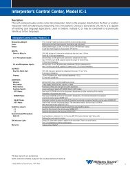
not helpful to the hearing impaired and can contribute to excessive noise in the receiveroutputs. See the section below, Deciding Between Compress Or Limit Settings.If an audio delay is available for use in large auditoriums, it’s usually best to use it.Because radio signals travel faster than sound, delaying the transmitted audio so that anaverage listener (in the middle of the listening area) hears the transmitted audio a fewmilliseconds after audio from the main sound reinforcement system speaker is helpful.This will also help audience members who lip read.The FM hearing assistance system transmits audio with very good fidelity, using thesame technical standards as commercial FM broadcast radio. Its quality is usually limitedby the audio source and by the earphones used with the receivers. Therefore, the audiosource signal should be of the highest quality possible.DECIDING BETWEEN COMPRESS OR LIMIT SETTINGSIt’s easy to select Compress or Limit using one position of the Audio Select Switch. Whenchoosing which mode to use, the system operator should consider the expected audience andprogram material. Figure 8 shows response curves for the compressor/limiter circuitry.A hearing impaired person’s perception of what is “too loud” is usually similar to a normalhearing person’s. However, they often don’t hear soft sounds as well. In other words, theirdynamic range is reduced. To compensate, the T4’s Audio Processor can compress the audiosignal, reducing the dynamic range and making it more useful to the hearing impaired.Some hearing impaired people cannot tolerate as loud a sound as those with normal hearing.When accompanied with hearing loss, their dynamic range is significantly reduced, both forsoft and for loud sounds. Compression is especially useful for these individuals.In some situations, however, such as concerts, compression is annoying to listeners—especially musical purists. Limiting provides control of the modulation level and isoptimized to cause a minimum of disturbance to the sound. It’s acceptable to the mostdiscerning listeners, but not as helpful to hearing impaired people as compression.FIGURE 8: T4 AUDIO PROCESSOR PERFORMANCE+100Hard Limiter (Always Functional)RELATIVE OUTPUT LEVEL–10–20CompressLimit–30Audio "-12 dB" Light ONAudio "0 dB" Light ON–40–40–30–20 –100RELATIVE INPUT LEVEL+10 +20<strong>Williams</strong> <strong>Sound</strong> ®Helping People Hear15
STEP 5:CONNECT THE POWER SUPPLYThe T4 transmitter is powered by a wall mounted transformer supplying 24 VAC. Plug thetransformer into a suitable 120 VAC outlet and connect the attached cable to the transmitter.The cable connector has a retaining catch which must be installed toward the top of thetransmitter as shown on the T4’s back panel. Though no damage will result, the T4 will notoperate if you install the cable upside down.Neither the T4, nor its power supply, are equipped with a power switch. Because there is no“wear out” mechanism and power consumption is minimal, continuous operation is not aproblem. If you want to control power to the transmitter, connect the power transformer to aswitched 120 VAC supply or a master switched outlet for the entire sound system.STEP 6:ADJUST THE AUDIO INPUT CONTROLPlay a compact disc or other quality audio source through the complete sound system at alevel that is typical of normal operation. Adjust the Audio Input control so that the LevelIndicator 0 dB LED generally lights and the +6 dB LED lights occasionally.16<strong>Williams</strong> <strong>Sound</strong> ®Helping People Hear
ASSURING EXCELLENT PERFORMANCEThe PPA 250 consists of a transmitter and several receivers used to deliver an audio signal tolisteners who are hard of hearing. The audio signal is usually provided by equipmentmanufactured and installed by others. The PPA 250 provides excellent audio performanceunder most conditions. However, <strong>Williams</strong> <strong>Sound</strong> equipment does not correct faults inincoming audio. This section is intended to help installers and users recognize properoperation and correct faults whenever possible.The following tests can be done without instruments to assure that a system is workingproperly.HOW TO RECOGNIZE PROPER OPERATIONStep 1: Play a compact disc through the complete sound system at a level that is typical ofnormal operation.Listen to the hearing assistance system using a receiver with a factory-suppliedearphone. Set the volume on the receiver at about 3. Comfortable listening isusually achieved with a setting of 2, or even lower. If you have normal hearing, avolume control setting of 3 will likely be too loud for comfortable listening. Thereshould be no audible distortion, hum or noise.<strong>Williams</strong> <strong>Sound</strong> wide band FM systems transmit audio using the same technicalstandards as FM Broadcast radio. Therefore, the received sound should be of highquality. Using a suitable adapter (Radio Shack Part #274-361), you can connect aprofessional headphone to a receiver for a critical evaluation.Step 2: Pause or stop the CD.There should be no significant increase in noise or hum immediately after thesound is stopped.Step 3: Play the CD again.Listen to the system using a receiver. Check for coverage in the listening area.Walk through and around the entire audience area. The sound in the receivershould remain clear and noise–free within the audience area.Some small spots in the listening area will seem to “dropout”, getting no signal.This is normal and is caused by RF signal reflections from relatively largeelectrically conductive objects. In most installations, the areas of reduced receptionare less than one foot wide and few in number. Moving the receiver only a fewinches usually restores reception.<strong>Williams</strong> <strong>Sound</strong> ®Helping People Hear17
RECEIVER USE INSTRUCTIONSRECEIVER MODEL PPA R7Receiver Model PPA R7 has a single, wheel-type volume control and an earphone output jack.BATTERY INSTALLATIONOpen the battery compartment using a coin in the slot in the bottom of the receiver. Press thebattery into place, observing proper battery polarity. Incorrect insertion of the battery isdifficult, and may cause both mechanical and electrical damage to the receiver not coveredby the 5 year warranty. The receiver will not work with the battery incorrectly installed.CONNECTING EARPHONESPlug an earphone into the jack near the thumb wheel volume control. Only monophonicearphones will operate properly. If stereo headphones are used, sound will be heard only inone side. A suitable adapter (Radio Shack Part #274-368), can be used so that stereoearphones operate on both sides. <strong>Williams</strong> <strong>Sound</strong> extensively evaluates the earphones andheadphones included with the PPA 250. We can only assure optimum performance when<strong>Williams</strong> sound earphones and headphones are used.OPERATING THE RECEIVERTurn the receiver on by rotating the volume control in the direction of the arrow on top of thecase. The “On” indicator will light.Turning the knob in the direction of the arrow will increase the volume. Turning the knobagainst the arrow will decrease the volume. To avoid depleting the battery, make sure thereceiver is turned off when not in use.If you’re using the PPA 250 with an existing sound system, make sure the sound system isturned on. Have someone speak into a sound system microphone while you listen with thereceiver and earphone. You should be able to hear their voice through the receiver.If you’re using the PPA 250 with a microphone—and not a complete sound system—havesomeone speak into the microphone while you listen with the receiver and earphone. Youshould be able to hear their voice through the receiver.Note:The earphone cord is the receiving antenna. Do not bunch up the cord or wrap itaround the receiver.ADDITIONAL RECEIVER INSTRUCTIONSMODELS PPA R7-4 AND PPA R7-6The R7-4 and R7-6 receivers feature a channel selector knob on top of the receiver. Turn theselector knob until you hear the desired program.MODEL PFM R16:The R16 Receiver features an environmental microphone input and dual volume controls.The taller knob turns the receiver on and off and controls the transmitted signal level. The18<strong>Williams</strong> <strong>Sound</strong> ®Helping People Hear
shorter knob controls the microphone signal level. By adjusting the two volume controls, youcan hear a mixture of the transmitted signal and nearby sounds.Note:Some users may not be helped by this system. Severe hearing loss may requireusing the system with a telecoil coupler (i.e., Neckloop) and personal hearing aid.USING A RECEIVER WITH A HEARING AID<strong>Williams</strong> <strong>Sound</strong> PPA Receivers can be used with hearing aids using three different methods:NECKLOOP TELECOIL COUPLERNeckloops are cords which hang around the neck and couple magnetically with T-Coilequipped hearing aids.SILHOUETTE TELECOIL COUPLERThese telecoil couplers are worn behind the ear, right next to telecoil-equipped hearing aids.DIRECT AUDIO INPUT (DAI) CORDDirect Audio Input cords can be used with compatible hearing aids as well as with CochlearImplant Processors.<strong>Williams</strong> <strong>Sound</strong> ®Helping People Hear19
BATTERY INFORMATIONDISPOSABLE BATTERIESIn normal use, a heavy-duty 9 Volt battery such as the Eveready 216 will last about 10 hours.Alkaline batteries such as the Eveready 522 will provide about 32 hours of use. If the soundbecomes weak or distorted, replace the battery. The indicator light may still be on, even witha battery that is weak. Do not leave dead batteries in the receivers. Battery corrosion is notcovered by the <strong>Williams</strong> <strong>Sound</strong> five year warranty.RECHARGEABLE BATTERIESThe R7 can also use 6 or 7 cell nickel cadmium rechargeable batteries. Optimal battery lifeis achieved with 7 cell batteries, such as the <strong>Williams</strong> <strong>Sound</strong> BAT 003. 6 cell batteries areusually marked “7.2 V”; 7 cell batteries are marked “8.4 V”. A fully charged 7 cell batterysuch as the BAT 003 will provide about 6 hours of operation per charge. Damage fromimproper charging is not covered by the <strong>Williams</strong> <strong>Sound</strong> five year warranty.The battery installed in the receiver may be recharged in the receiver only if it is a NickelCadmium battery, and only if the correct <strong>Williams</strong> <strong>Sound</strong> charger is used.Recharge batteries only with a <strong>Williams</strong> <strong>Sound</strong> BAT 005 Single Charger or a <strong>Williams</strong> <strong>Sound</strong>CHG 1269A Multiple Charger. The charger is connected to the receiver through the EARjack. Make sure the receiver is turned off during charging. A complete recharge cycle takesabout 14 hours. Receivers should not be left charging continuously when not in use.!! IMPORTANT WARNINGS !!DO NOT ATTEMPT TO RECHARGE ZINC CARBON (“HEAVY DUTY”), ALKALINE, ORLITHIUM BATTERIES!DO NOT ATTEMPT TO RECHARGE DISPOSABLE BATTERIES! These batteries may heat upand explode, causing possible injury and damage to the equipment.Avoid shorting the plus and minus battery terminals together with metal objects. Batterydamage and burns can result!Use only <strong>Williams</strong> <strong>Sound</strong> Supplied chargers and batteries!20<strong>Williams</strong> <strong>Sound</strong> ®Helping People Hear
FREQUENCY CHANGE INSTRUCTIONSNormally, the PPA 250’s factory-set channel (usually 72.9 MHz) requires no change.However, if another hearing assistance system or authorized radio service is operating on72.9 MHz in your area, it may prove necessary to use an alternate channelIn this event, the PPA System 250’s operating frequency can easily be changed to an alternatechannel to avoid interference.See the following sections for instructions on changing frequencies.TRANSMITTER FREQUENCY CHANGE PROCEDURE:Set the T4 Transmitter to any of the 10 available channels using the FM Channel/FM PowerSwitch. See figure 9.IMPORTANT: Some cities have other radio services licensed on hearing assistancechannels. Under FCC rules governing hearing assistance, you must yield tothem. A list of cities where other radio services are known to exist isincluded with the transmitter. Do not use frequencies that are known to beused by licensed radio services in your city, either if they are on the list or ifyou discover one.Figure 9: FM Channel/FM Power Switch SettingsRF CONFIG SWITCHSWITCH SETTINGS1 2 3 4 5FREQUENCY72.100 MHz ON ON ON ON OFF72.300 MHz ON ON OFF ON OFF72.500 MHz ON OFF ON ON OFF72.700 MHz ON OFF OFF ON OFF72.900 MHz OFF ON ON ON OFF74.700 MHz OFF ON OFF OFF ON75.300 MHz ON ON ON OFF OFF75.500 MHz ON ON OFF OFF OFF75.700 MHz ON OFF ON OFF OFF75.900 MHz ON OFF OFF OFF OFFRF OUTPUT POWERFULLHALFQUARTEROFF6 7 8OFF OFFOFFONONOFFON ONSwitches 1-5 toggles controlfrequency settingsSwitch 6 is not usedSwitches 7 and 8 control RF outputpower. The factory setting is FULL, andcan be adjusted if conditions warrant.See Troubleshooting Guide.Remember: If you change thetransmitter frequency, you must alsochange receiver frequencies.“On” and “Off are labeled on thebody of the DIP switches.<strong>Williams</strong> <strong>Sound</strong> ®Helping People Hear21
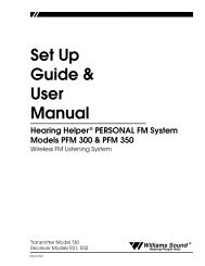
RECEIVER FREQUENCY CHANGE INSTRUCTIONSFIGURE 10: R7 RECEIVER TUNINGTuning CoilThis is a small, square, bright metal can with ascrewdriver slot in the top center. Using a plastictuning tool (PLT 005), rotate the Tuning Coilslowly and gently. Do not press down on theadjustment. When you find the signal transmittedby your system, adjust for the loudest and clearestsound possible.Tuning for the R7 and R-16 Receivers is determined by a single tuning coil. (See Figure 10.)A plastic tuning wrench (PLT 005) is needed to adjust the receiver tuning coil.Most <strong>Williams</strong> <strong>Sound</strong> receivers, including R7’s, are set at the factory to 72.9 MHz. (Yoursmay have been set to another channel when they were ordered.) To change the frequency ofR7 receivers:Step 1:Step 2:Step 3:Step 4:Step 5:Step 6:The receiver must be tuned under moderate or weak signal conditions. Set the T4Transmitter’s RF Output Power to QUARTER. (See Figure 9.) Play a CD orcassette through the sound system, or have someone speak into a microphone.Make sure the transmitter is set for the channel to which you want to tune thereceiver, then move 50-75 feet away from the transmitting antenna.Open the battery compartment, then lift up on the battery flap to open the back ofthe receiver. This will expose the circuit board.Locate the tuning coil. (See Figure 10.) The only adjustable item in the unit, thetuning coil is a small, square, bright metal can with a screwdriver slot in the topcenter.Use the earphone supplied with the receiver to listen for the transmitted signal.Slowly and gently rotate the tuning coil with a plastic tuning tool(PLT 005), Do not press down on the coil. When you find the signal transmitted byyour system, adjust for the loudest and clearest sound possible.Re-tune all the receivers, marking the new frequency inside each’s case for futurereference.22<strong>Williams</strong> <strong>Sound</strong> ®Helping People Hear
SUGGESTIONS FOR RECEIVER MANAGEMENTDifferent types of facilities use varying approaches to receiver management and earphonesanitation. Below are some options that customers have used successfully.1. Regular users purchase or are given their own receiver and take care of their ownbatteries and earphones.2. The facility labels a receiver and earphone for each regular user. The facilitymaintains the units.3. Ushers issue receivers to people who request them.Earphones are sanitized after use. Foam ear cushions can be replaced or washedwith a mild detergent, rinsed thoroughly and air-dried. The EAR 022 SurroundEarphone can be sanitized with an alcohol pad.The receivers can be stored in a multiple compartment storage case with a creditcard or driver’s license left as collateral for the receiver.4. Regular users purchase their own earphone or headphone and bring them to usewith receivers at the facility.<strong>Williams</strong> <strong>Sound</strong> ®Helping People Hear23
TROUBLE SHOOTING GUIDENO TRANSMITTER OPERATIONPOWER LIGHT NOT ONMost likely, there is no power. Make sure the power outlet is working and that the PPA250’s power supply (TFP 016) is connected correctly.AUDIO DIFFICULTIES (AS HEARD IN PHONES JACK ON TRANSMITTER)NO AUDIO HEARD IN PHONES JACKCheck to see if there is a signal coming from your audio source. Check and correct youraudio source if necessary.Check to see if the Audio Level control has been turned all the way down. If so, adjust it.Check to see if there is an incorrect or defective connection from your audio source. Seepage 13-14 for detailed connection instructions.NOISE IN AUDIOCheck to see if there is noise in source audio. To find out, disconnect the audio cable. Ifthe noise disappears you noise problem is in the source. Correct or repair your audiosource.Check to see if your source level is too low. If so, readjust your source audio level orreset Audio Select switch to match the existing source level.BUZZ OR HUM IN AUDIOCheck to see if the buzz or hum in in the source. If so, correct or repair your audiosource.Check to see if there is an incorrect or defective connection from source. If so, correctyour connections. See page 13-14 for detailed instructions.DISTORTED AUDIOCheck to see if the source audio is distorted source. If so, correct or repair your audiosource.Perhaps the Audio Select switch is not set to match your audio source. If this is the case,reset the Audio Select switch to match and/or readjust the source.Check to see if the Audio Level control is set too high. If the +6 level indicator is on allthe time, adjust the Level control counter–clockwise.If the Audio Level control is set near fully counter–clockwise, the Audio Select switch isset incorrectly. Set Audio Select switch to match your audio source and/or readjust thesource.24<strong>Williams</strong> <strong>Sound</strong> ®Helping People Hear
NOISE IN AUDIO “GROWS” WHEN PROGRAM IS SILENTThe Audio Level control is set too high. You’re probably also seeing the +6 levelindicator lighting all the time. To correct, adjust the Audio Level control.It could be that the T4’s Audio Processor is set for Compress when Limit might be moreappropriate for the type of program being transmitted. Reset the Audio Select switch forLimit. See page 15.RECEPTION (AT RECEIVER) DIFFICULTIESCheck Audio Difficulties (as heard in phones jack on transmitter) before checking reception.NO RECEPTIONIf the the T4’s RF Indicator LED is not on, it’s possible that an invalid channel is set onthe FM Channel/FM Power Switch. Reset this switch to a valid channel.Check to see if the antenna has been disconnected. If so, attach the antenna correctly.Check to see if the output power is set to “OFF”. If so, reset the FM Channel/FM PowerSwitch for FULL, HALF, or QUARTER RF output.INSUFFICIENT RANGE, GOOD RECEPTION NEAR TRANSMITTER, POOR AT A DISTANCECheck to see if the transmitting antenna was installed incorrectly. If so, correct or replacethe antenna. The signal should be clearly audible at a 300 foot distance with theANT 021 and a 500 foot distance with the ANT 005.Make sure the transmitting antenna is not in an unsuitable location.Perhaps the transmitting antenna was installed inside a metal enclosure or is separatedfrom the reception area by electrically conducting objects. (i.e., steel stud walls, heatingducts, substantial structural steel, or 2x2 or 2x4 ceiling grid.) In either case, reinstall theantenna according to installation instructions, locating it outside metal enclosures andaway from electrically conducting objects.Perhaps there is a strong interfering signal. If so, make sure the transmitter and antennaare correctly installed. Set the transmitter to FULL power output. If this does not solvethe problem, change the PPA 250’s frequency by setting the FM Channel/FM PowerSwitch according to the instructions on page 24.0DROPOUTS: AREAS OF NO RECEPTION WITHIN NORMAL RECEPTION AREAIf dropout areas are few and less than 2 feet across, there is no problem. This is part ofnormal operation.If dropouts are many and large, see the section on insufficient range above.POPS OR SIMILAR LARGE DEFECTS IN RECEIVED AUDIOCheck to see if there is defective audio at the transmitter. If so, See the Audio Difficultiessection.Check to see if the receivers are incorrectly tuned. If so, adjust receiver according toinstructions on page 20.<strong>Williams</strong> <strong>Sound</strong> ®Helping People Hear25
Check to see if there is a strong interfering signal by listening to the receiver with thetransmitter turned off. If an interfering signal is causing overload in the receivers, see thesection on insufficient range above. If changing channels does not remedy the problem,use other technology, such as <strong>Williams</strong> <strong>Sound</strong> Narrow Band FM or <strong>Williams</strong> <strong>Sound</strong>Infrared.USERS MUST TURN RECEIVER VOLUME CONTROLS WAY UP (TO 4 OR 5) TO GET ENOUGH VOLUME Perhaps there is insufficient audio level. If so, the audio level indicator will read too lowbecause the audio level is set incorrectly on the transmitter. Correct the Audio Levelcontrol setting.It could be that the input is not configured for the audio source used. If not, correct thesetting of the Audio Select switch.Some users may not be helped by this system. Severe hearing loss may require using thesystem with a telecoil coupler (i.e., Neckloop) and personal hearing aid.USERS COMPLAIN OF NOT HEARING LOW LEVEL SOUNDSCheck to see if the Audio Level is set too low. If so, adjust the Audio Level, carefullynoting the Level Indicator. The +6 LED should light occasionally.Check to see if the transmitter is set for Limit when the program material would benefitfrom Compress mode. If so, set the Audio Select switch for Compress.USERS COMPLAIN OF TOO MUCH NOISE DURING SOFT AUDIO. DYNAMIC RANGE OF MUSIC REDUCED TOOGREATLY.Check to see if the Audio Level control is set too high. This problem is more likely tooccur in Compress Mode, but can also occur in Limit Mode. To reduce this noise, adjustthe Audio Level, carefully noting the Level Indicator. The +6 LED should lightoccasionally.Perhaps the transmitter is set for Compress when Limit Mode would be more suitable,given the program material. If so, set the Audio Select switch for Limit.BUZZ IN OTHER EQUIPMENT WHEN TRANSMITTER IS ON OR OFFThis is not an RF problem. Instead, it is likely caused by incorrect audio connections, aground loop, or defective equipment. To remedy, use proper audio wiring practice tomake connections described on page 14.BUZZ OR OTHER NOISE IN EQUIPMENT ONLY WHEN TRANSMITTER IS ONThis is likely an RF–induced disturbance in the other equipment. To remedy, try thesesteps in order until the buzz is eliminated:1. Make certain the transmitter chassis is connected to the equipment cabinet rails.2. Make sure antenna connections are secure.3. Set the T4 Transmitter to HALF or QUARTER power output using theFM Channel/FM Power Switch.4. <strong>Install</strong> transmitter at a distance from sensitive equipment.5. Use a remote antenna. (ANT 005 or ANT 024)6. Make sensitive equipment more immune to RFI/EMI. The manufacturers of your26<strong>Williams</strong> <strong>Sound</strong> ®Helping People Hear
audio equipment may offer application notes for this purpose.<strong>Williams</strong> <strong>Sound</strong> offers a document giving suggestions forimproving RF immunity in existing audio equipment. (TechnicalBulletin: Buzz Or Hum In The <strong>Sound</strong> System, FRM 531)WARRANTYThe <strong>Williams</strong> <strong>Sound</strong> T4 Transmitter and R7, R7-4, R7-6, and R16 Receiversare warranted against defects in workmanship and materials for FIVEYEARS.Microphones, earphones, cables, carry cases, rechargeable batteries andchargers are warranted against defects in workmanship and materials forNINETY DAYS.This warranty does not extend to intentional or accidental physical damage.This warranty applies only to products returned to <strong>Williams</strong> <strong>Sound</strong> forservice.To return a product for service, call 1-800-843-3544 and request a ReturnAuthorization (RA) number.<strong>Williams</strong> <strong>Sound</strong> ®Helping People Hear27
Pro Wide–band System, Model PPA 250 SPECIFICATIONSPERSONAL PA Transmitter Model T4Dimensions, Weight: 8.45" (21.5 cm) W x 8.18" (20.8 cm) Dx 1.72" (4.4 cm) H, 3lbs. (1.5 kg)Color:Black epoxy paint with white legendsRack Mount:One EIA rack space high, 1/2 space wide1–2 units can be mounted in a single rackspace with optional RPK 005 (single) orRPK 006 (double) Rack Mount KitsPower:21 VAC minimum; 26 VAC maximum,50 or 60 Hz 4.8 VA nominal; 10 VA maximum;Wall mount transformer for 105 to 130 VACincludedFCC ID:CNMT4Operating Freqs: 72.1–75.9 MHz *10 wide–band channels, selectableFrequency Accuracy: ±.005% stability, 0-50˚ CDeviation:± 75 kHz maximumPre-Emphasis:75 µsecRF Field Strength: Does not exceed 8 mV/m at 3 mNominal Range: 300-500 ft. (90-150 m)Audio Proc. Functions: Soft Knee Limit or CompressCompression 10 dB add’l gain when input is –20 dB20 dB add’l gain when input is –40 dBSoft Limiting > 10 dB add’l gain when input is –45 dBFrequency Response: 30 – 16000 Hz, +1, -3 dBSignal to Noise Ratio: More than 70 dB below 75 kHz deviationin Limit modeNote:Maximum transmitter range is achievedusing the ANT 005 coaxial antennaT4 Transmitter Front PanelPPA T4 Professional FM Auditory Assistance TransmitterFrequency Synthesized, Channel-SelectableAudio AdjustAudio LevelPower -12dB -6dB 0dB +6dBRF Carrier<strong>Williams</strong> <strong>Sound</strong>PhonesDecreaseIncreaseLoOkOkToo HiPower Indicator:Audio Level Control:Green LEDRotary pot, screwdriver adjust,used with audio level indicator lightsAudio Level Indicators: 4 LED array, reads -12, -6, 0, and +6 dBRF Carrier On Indicator: Green LED indicates transmitter RF is onPhones Jack:1/4" TRS (Stereo) jackT4 Transmitter Rear PanelAudio SelectAudio Input(XLR) Bal. MicBal./Unbal line or 70V(TRS) Bal./Unbal .Line or 70VModel PPA T4 Auditory Assistance FM Transmitter<strong>Williams</strong> <strong>Sound</strong> Corp., Minneapolis, MN USALine OutFM Channel,PowerAntennaPower: 24 VAC,50-60 Hz, 10VA1 2 3 4 5 6 7 8 1 2 3 4 5 6 7 8To configure, see chart on top.See chart on top.75 OhmsPlugAudio Select Switch: Eight–section DIP switchAudio Input:Combination 3-pin XLR, 1/4" TRS jackLine Output:RCA jack, 0.6 V output impedance 1000 ΩFM Channel Switch: Eight–section DIP switch (Seven used)Antenna Outputs: Hard-wired 75 Ω Coaxial Antenna (ANT 005)uses RG-59 cable, 400 ft. (122 m) max.cable lengthPERSONAL PA Receiver, Model PPA R7Power Connections: 3-pin Molex ® connectorInput Levels Minimum Nominal MaximumMicrophone 100 µV 1 mV 100 mVBal or Unbal Line 10 mV 100 mV 10 VBal or Unbal or70 V speaker line 2.3 V 23 V 230 VIMPORTANT: If you choose to connect to 70 Volt Speaker line,be certain to set the Audio Config switch correctly. Severedamage will occur if you do not.Dimensions & Weight: 3-5/8" L x 2-3/8" W x 7/8" H(92.1 mm x 60.3 mm x 22.2 mm)3.2 oz (90 g) with batteryColor:GrayBattery Type:9 Volt, Eveready 216 Carbon Zinc,Eveready 522 Alkaline, or BAT 003 Ni-CadBattery Drain:14 mA, nominalBattery Life: 10 hours with Eveready 21632 hours with Eveready 5226 hours/charge with BAT 003FCC ID:CNM R7YOperating Freq.: Pre-Tuned, Adjustable, 72 MHz - 76 MHz *Intermediate Freq.: 70 kHzFM Deviation:75 kHzDe-Emphasis: 75 µS* Note: FCC Rules limit the use of the 72–79 MHz band to hearing assistance for the handicapped only.Your Authorized <strong>Williams</strong> <strong>Sound</strong> Dealer Is:<strong>Williams</strong> <strong>Sound</strong> Corp.10399 West 70th St., Eden Prairie, MN 55344-3459U.S.A. 800-328-6190 / 952-943-2252 / FAX: 952-943-2174AFC Range:± 300 kHzSensitivity:2 µV at 12 dB Sinad with squelch defeatedSquelch:Squelches at 10 µV for min. 50 dB S/N ratioInput Overload: 20 mVFrequency Response: 100 – 10 kHz, ± 3 dBSignal-to-Noise Ratio: 50 dB at 10 µVReceive Antenna: Integral with earphone/headphone cordAudio Output:250 mW, max. at 16 OhmsOutput Connector: 3.5 mm mini phone jack, also serves as acharging jack for rechargeable batteryEarphone:Earbud-type with foam cushion,3.5 mm plug, 32 ΩNote:The R7 Receiver can be field tuned to any of10 wideband channels using the PLT 005Tuning Tool.www.williamssound.com © 2000, <strong>Williams</strong> <strong>Sound</strong> Corp. MAN 071 D