Flier: Strong-Drive® Structural Wood Screws for Interior and Exterior ...
Flier: Strong-Drive® Structural Wood Screws for Interior and Exterior ...
Flier: Strong-Drive® Structural Wood Screws for Interior and Exterior ...

You also want an ePaper? Increase the reach of your titles
YUMPU automatically turns print PDFs into web optimized ePapers that Google loves.
STRONG-DRIVE ®<br />
STRUCTURAL<br />
WOOD SCREWS<br />
<strong>for</strong> <strong>Interior</strong> <strong>and</strong> <strong>Exterior</strong><br />
Fastening Applications<br />
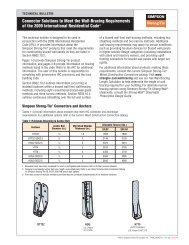
Easy to Drive Washer Head Tested Per<strong>for</strong>mance
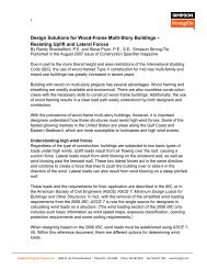
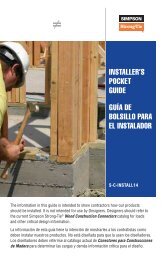
<strong>Strong</strong>-Drive ® <strong>Structural</strong> <strong>Wood</strong> <strong>Screws</strong><br />
High Strength <strong>and</strong> Easy<br />
Installation <strong>for</strong> <strong>Interior</strong> <strong>and</strong><br />
<strong>Exterior</strong> Applications<br />
Simpson <strong>Strong</strong>-Tie has exp<strong>and</strong>ed the<br />
<strong>Strong</strong>-Drive ® SDW wood screw product<br />
line with two new screws designed to<br />
provide an easy-to-install, high-strength<br />
alternative to through-bolting <strong>and</strong> traditional<br />
lag screws. The new SDWS <strong>and</strong> SDWH<br />
structural wood screws are ideal <strong>for</strong> the<br />
contractor <strong>and</strong> do-it-yourselfer alike.<br />
Features:<br />
• Bold thread design provides<br />
superior holding power<br />
• Patented 4CUT tip ensures<br />
fast starts, reduces installation<br />
torque <strong>and</strong> eliminates the need <strong>for</strong><br />
pre-drilling in most applications<br />
• Under-head nibs offer greater installer<br />
control when seating the head<br />
• Large washer head provides<br />
maximum bearing area<br />
SDWS<br />
(6-lobe drive)<br />
SDWH<br />
(Hex head)<br />
F-SDWSSDWH12C © 2012 Simpson <strong>Strong</strong>-Tie Company Inc.<br />
2
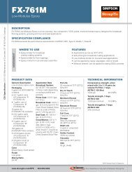
SDWS <strong>Structural</strong> <strong>Wood</strong> <strong>Screws</strong><br />
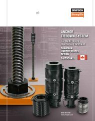
<strong>Strong</strong>-Drive ® SDWS<br />
<strong>Structural</strong> <strong>Wood</strong> Screw<br />
The Simpson <strong>Strong</strong>-Tie ® <strong>Strong</strong>-Drive ® SDWS wood screw is<br />
specifically designed <strong>for</strong> structural wood-to-wood applications<br />
<strong>and</strong> is also ideal <strong>for</strong> a wide variety of projects where a highstrength<br />
attachment is needed. This 0.220" diameter fastener<br />
requires less torque to install than comparable fasteners,<br />
making it easier to drive, <strong>and</strong> the corrosion-resistant coating<br />
makes it suitable <strong>for</strong> interior or exterior applications.<br />
Features:<br />
• Deep, 6-lobe recess<br />
reduces cam-out, making<br />
driving easier<br />
• Low-profile head design<br />
provides a clean look <strong>and</strong><br />
less interference after<br />
installation<br />
• Double-barrier coating<br />
provides corrosion resistance<br />
equivalent to hot-dip<br />
galvanization, making it<br />
suitable <strong>for</strong> certain exterior<br />
<strong>and</strong> preservative-treated<br />
wood applications<br />
The 6-lobe drive prevents<br />
cam-out <strong>and</strong> head stripping<br />
L<br />
0.220"<br />
TL<br />
0.75"<br />
SDWS<br />
U.S. Patents 5,897,280;<br />
7,101,133, <strong>and</strong> patent pending<br />
Identification on all<br />
SDWS screw heads<br />
Lengths<br />
3"<br />
4"<br />
5"<br />
6"<br />
8"<br />
10"<br />
Stamp<br />
WS22<br />
3<br />
WS22<br />
5<br />
WS22<br />
8<br />
WS22<br />
4<br />
WS22<br />
6<br />
WS22<br />
Installs best with a<br />
low-speed 1 ⁄2" drill<br />
motor with a T-40 bit<br />
(bit included in each package).<br />
10<br />
Available in retail packs<br />
as well as mini-bulk <strong>and</strong><br />
bulk buckets<br />
F-SDWSSDWH12C © 2012 Simpson <strong>Strong</strong>-Tie Company Inc.<br />
The SDWS screw is designed <strong>for</strong> structural fastening<br />
applications such as deck ledgers.<br />
Easy to drive.<br />
3
SDWS <strong>Structural</strong> <strong>Wood</strong> <strong>Screws</strong><br />
SDWS Screw Product In<strong>for</strong>mation<br />
Size<br />
Dia. x L<br />
(in.)<br />
Fasteners<br />
Per Pack<br />
Retail Pack 1 Mini-Bulk Bucket 1 Mini-Bulk 1 Bulk 1<br />
Packs<br />
Per<br />
Master<br />
Carton<br />
Model No.<br />
Fasteners<br />
Per Pack<br />
Packs<br />
Per<br />
Master<br />
Carton<br />
Model No.<br />
Fasteners<br />
Per Pack<br />
Model No.<br />
Fasteners<br />
Per Pack<br />
Model No.<br />
0.220 x 3 12 10 SDWS22300DB-RC12 50 6 SDWS22300DB-R50 250 SDWS22300DBMB 950 SDWS22300DB<br />
0.220 x 4 12 10 SDWS22400DB-RC12 50 6 SDWS22400DB-R50 250 SDWS22400DBMB 600 SDWS22400DB<br />
0.220 x 5 12 10 SDWS22500DB-RC12 50 6 SDWS22500DB-R50 250 SDWS22500DBMB 600 SDWS22500DB<br />
0.220 x 6 12 10 SDWS22600DB-RC12 50 6 SDWS22600DB-R50 250 SDWS22600DBMB 500 SDWS22600DB<br />
0.220 x 8 12 10 SDWS22800DB-RC12 50 6 SDWS22800DB-R50 250 SDWS22800DBMB 400 SDWS22800DB<br />
0.220 x 10 12 10 SDWS221000DBRC12 50 6 SDWS221000DB-R50 — — 250 SDWS221000DB<br />
1. Retail <strong>and</strong> mini-bulk packs include one deep, 6-lobe, T-40 driver bit; bulk packs include two driver bits.<br />
Factored Resistances <strong>for</strong> D.Fir-L Members (lbs.)<br />
Size<br />
Dia. x L<br />
(in.)<br />
See footnotes below.<br />
Model<br />
Thread<br />
Length<br />
TL<br />
(in.)<br />
D.Fir-L<br />
Factored Lateral Resistance (K D<br />
=1.00)<br />
<strong>Wood</strong> Side Member Thickness (in.)<br />
1.5 2 2.5 3 3.5 4 4.5 6 8<br />
Factored<br />
Withdrawal<br />
Resistance<br />
0.220 x 3 SDWS22300DB 1½ 340 — — — — — — — — 485<br />
0.220 x 4 SDWS22400DB 2⅜ 445 455 430 — — — — — — 795<br />
0.220 x 5 SDWS22500DB 2¾ 445 505 540 490 430 — — — — 935<br />
0.220 x 6 SDWS22600DB 2¾ 460 515 565 565 560 505 445 — — 935<br />
0.220 x 8 SDWS22800DB 2¾ 460 515 565 565 565 565 565 505 — 935<br />
0.220 x 10 SDWS221000DB 2¾ 460 515 565 565 565 565 565 565 505 935<br />
L<br />
TL<br />
Factored Resistances <strong>for</strong> S-P-F Members (lbs.)<br />
Size<br />
Dia. x L<br />
(in.)<br />
Model<br />
Thread<br />
Length<br />
TL<br />
(in.)<br />
1. Factored resistances shown have been developed in accordance with 10.11<br />
CSA O86-09 based on testing per ICC-ES AC233. Apply the adjustment factors<br />
K D<br />
, K SF<br />
<strong>and</strong> K T<br />
as per 10.11.4.1 when applicable. Do not install in end grain.<br />
2. Factored withdrawal resistances shown are only applicable<br />
to short term loads as per 10.11.5.1 CSA O86-09.<br />
3. Factored withdrawal resistances shown assume the entire threaded portion<br />
of the screw is installed into the main member. Where the penetration<br />
S-P-F<br />
Factored Lateral Resistance (K D<br />
=1.00)<br />
<strong>Wood</strong> Side Member Thickness (in.)<br />
1.5 2 2.5 3 3.5 4 4.5 6 8<br />
into the main member is less than the length of the thread, the factored<br />
resistances may be calculated by multiplying the length of penetration<br />
of the threads x 355 lbs/in (62 N/mm) <strong>for</strong> D.Fir-L <strong>and</strong> 270 lbs/in (47<br />
N/mm) <strong>for</strong> S-P-F. to a maximum of the tabulated value above.<br />
4. Minimum spacing, edge <strong>and</strong> end distances shall be in accordance with<br />
10.9.2.1 CSA O86-09 using a diameter value of 0.30". See table below.<br />
5. Divide table value by 224.8 to convert to kN (1 kN = 224.8 lbs).<br />
Factored<br />
Withdrawal<br />
Resistance<br />
0.220 x 3 SDWS22300DB 1½ 290 — — — — — — — — 370<br />
0.220 x 4 SDWS22400DB 2⅜ 390 390 380 — — — — — — 605<br />
0.220 x 5 SDWS22500DB 2¾ 395 445 485 430 380 — — — — 620<br />
0.220 x 6 SDWS22600DB 2¾ 405 455 505 510 495 445 395 — — 620<br />
0.220 x 8 SDWS22800DB 2¾ 405 455 505 510 510 510 510 445 — 620<br />
0.220 x 10 SDWS221000DB 2¾ 405 455 505 510 510 510 510 510 445 620<br />
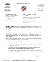
Spacing Requirements<br />
Geometry<br />
Minimum Dimensions<br />
(in)<br />
D.Fir-L<br />
S-P-F<br />
a - Spacing parallel to grain 6 5<br />
b - End distance parallel to grain 6 6<br />
c - Spacing perpendicular to grain 3 2 1 ⁄2<br />
d - Edge distance perpendicular to grain 1 7 ⁄16 1 7 ⁄16<br />
6" Min.<br />
end distance<br />
(b)<br />
Spacing<br />
between<br />
fasteners<br />
perpendicular<br />
to grain<br />
(c)<br />
1 7 ∕16" Min.<br />
edge distance<br />
(d)<br />
Spacing between fasteners<br />
parallel to grain<br />
(a)<br />
F-SDWSSDWH12C © 2012 Simpson <strong>Strong</strong>-Tie Company Inc.<br />
1. Additional screws may be staggered diagonally between rows.<br />
Spacing Requirements<br />
4
SDWS <strong>Structural</strong> <strong>Wood</strong> <strong>Screws</strong><br />
Maximum Fastener Spacing <strong>for</strong> Solid Sawn Lumber Deck Ledger to Rim Board (in.)<br />
Ledger<br />
Size<br />
2x<br />
Model<br />
SDWS22400DB<br />
2-2x SDWS22500DB<br />
Specified<br />
Live Load<br />
40 psf<br />
(1.9 kPa)<br />
50 psf<br />
(2.4 kPa)<br />
100 psf<br />
(4.8 kPa)<br />
40 psf<br />
(1.9 kPa)<br />
50 psf<br />
(2.4 kPa)<br />
100 psf<br />
(4.8 kPa)<br />
Rim Board<br />
1. Solid Sawn lumber ledger board shall be a minimum of 2x8<br />
or 2-2x8. Spacings apply to S-P-F, Hem-Fir or D.Fir-L.<br />
2. Minimum structural panel thickness shall be 0.30" (7.5 mm)<br />
fastened to the rim board per applicable code.<br />
3. Multi-ply 2-2x ledger board must be fastened together to<br />
act as one unit independent of the SDWS screws.<br />
4. Spacing requirements are based on testing per ICC-ES AC233 <strong>and</strong> AC13 modified<br />
to meet the requirements of 10.11 CSA O86-09 assuming wet service conditions.<br />
For dry service conditions, multiply the tabulated spacing values by 1.5.<br />
Maximum Deck Joist Span (ft.)<br />
6 8 10 12 14 16<br />
1" OSB 10 7 6 5 4 3<br />
1⅛" OSB 10 8 6 5 4 4<br />
1¼" LSL 11 8 6 5 4 4<br />
2x SPF 12 9 7 6 5 4<br />
1" OSB 8 6 5 4 3 3<br />
1⅛" OSB 9 6 5 4 3 3<br />
1¼" LSL 9 7 5 4 4 3<br />
2x SPF 10 7 6 5 4 3<br />
1" OSB 4 3 — — — —<br />
1⅛" OSB 4 3 — — — —<br />
1¼" LSL 5 3 3 — — —<br />
2x SPF 5 4 3 — — —<br />
1" OSB 13 10 8 6 5 5<br />
1⅛" OSB 14 10 8 7 6 5<br />
1¼" LSL 14 11 8 7 6 5<br />
2x SPF 15 11 9 7 6 5<br />
1" OSB 11 8 6 5 4 4<br />
1⅛" OSB 11 8 7 5 5 4<br />
1¼" LSL 12 9 7 6 5 4<br />
2x SPF 12 9 7 6 5 4<br />
1" OSB 6 4 3 3 - -<br />
1⅛" OSB 6 4 3 3 - -<br />
1¼" LSL 6 4 3 3 - -<br />
2x SPF 6 5 4 3 - -<br />
5. Tabulated values are based on the listed specified live loads in<br />
combination with 10 psf (0.50 kPa) specified dead load.<br />
6. For 1¼" LVL rim board made with Douglas Fir or Southern<br />
Pine veneers, use the values listed <strong>for</strong> 1¼" LSL.<br />
7. SDWS screws shall be placed no less than 1½" from the top <strong>and</strong> bottom of the<br />
ledger or rim boards. The minimum end distance shall be 6" <strong>and</strong> the minimum<br />
spacing perpendicular to grain shall be 3". See figures below <strong>for</strong> full details.<br />
F-SDWSSDWH12C © 2012 Simpson <strong>Strong</strong>-Tie Company Inc.<br />
<strong>Exterior</strong> cladding<br />
<strong>and</strong> flashing not<br />
shown <strong>for</strong> clarity<br />
Floor<br />
joist or<br />
blocking<br />
Rim board<br />
per Table<br />
Ledger-to-Rim Board Assembly<br />
(<strong>Wood</strong>-framed lower floor acceptable,<br />
concrete wall shown <strong>for</strong> illustration purposes)<br />
<strong>Wood</strong> structural<br />
panel sheathing<br />
7.5 mm min. thickness<br />
fastened per code<br />
SDWS wood screws<br />
stagger vertically<br />
space in accordance<br />
with Table<br />
2" nominal deck<br />
ledger shown<br />
(double 2"<br />
ledger similar)<br />
1 1 ⁄2" minimum from<br />
top of ledger <strong>and</strong> rim board<br />
6" from end<br />
of ledger<br />
On-center<br />
spacing of<br />
SDWS wood<br />
screws<br />
SDWS Screw Spacing Detail<br />
1 1 ⁄2" minimum from<br />
bottom of ledger<br />
<strong>and</strong> rim board<br />
3" minimum<br />
row spacing<br />
5
SDWH <strong>Structural</strong> <strong>Wood</strong> <strong>Screws</strong><br />
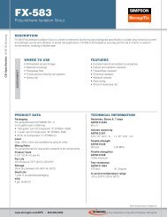
<strong>Strong</strong>-Drive ® SDWH<br />
<strong>Structural</strong> <strong>Wood</strong> Screw<br />
The Simpson <strong>Strong</strong>-Tie ® <strong>Strong</strong>-Drive ® SDWH screw<br />
is ideal <strong>for</strong> structural <strong>and</strong> general-purpose fastening<br />
applications where a hex-head drive is preferred. This<br />
0.195" diameter fastener requires less torque to install<br />
than comparable fasteners, making it easier to drive;<br />
while the corrosion-resistant coating makes it suitable<br />
<strong>for</strong> interior <strong>and</strong> exterior applications.<br />
Features:<br />
• Large hex-washer head<br />
provides excellent bearing<br />
area <strong>for</strong> a secure connection<br />
• Hex drive reduces cam-outs<br />
<strong>for</strong> easier driving<br />
• Double-barrier coating<br />
provides corrosion resistance<br />
equivalent to hot-dip<br />
galvanization, making it<br />
suitable <strong>for</strong> certain exterior<br />
<strong>and</strong> preservative-treated<br />
wood applications<br />
Hex-washer head provides<br />
excellent bearing area<br />
L<br />
0.195"<br />
TL<br />
0.64"<br />
SDWH<br />
U.S. Patents 5,897,280;<br />
7,101,133, <strong>and</strong> patent pending<br />
Identification on all<br />
SDWH screw heads<br />
Lengths<br />
3"<br />
4"<br />
6"<br />
8"<br />
10"<br />
Stamp<br />
193<br />
196<br />
1910<br />
194<br />
198<br />
Installs best with a<br />
low-speed 1 ⁄2" drill motor<br />
with a 5 ⁄16" hex driver<br />
(driver included in each package)<br />
Available in retail packs<br />
as well as mini-bulk <strong>and</strong><br />
bulk buckets<br />
The SDWH can replace multiple smaller fasteners<br />
in many applications.<br />
The SDWH screw is designed <strong>for</strong> structural fastening<br />
applications such as ledgers.<br />
F-SDWSSDWH12C © 2012 Simpson <strong>Strong</strong>-Tie Company Inc.<br />
6
XXX<br />
XXX<br />
XXX<br />
XXX<br />
XXX<br />
SDWH <strong>Structural</strong> <strong>Wood</strong> <strong>Screws</strong><br />
SDWH Screw Product In<strong>for</strong>mation<br />
Size<br />
Dia. x L<br />
(in.)<br />
Fasteners<br />
Per Pack<br />
Retail Pack 1 Mini-Bulk Bucket 1 Mini-Bulk 1 Bulk 1<br />
Packs<br />
Per<br />
Master<br />
Carton<br />
Model No.<br />
Fasteners<br />
Per Pack<br />
Packs<br />
Per<br />
Master<br />
Carton<br />
Model No.<br />
Fasteners<br />
Per Pack<br />
Model No.<br />
Fasteners<br />
Per Pack<br />
Model No.<br />
0.195 x 3 12 10 SDWH19300DB-RC12 50 6 SDWH19300DB-R50 250 SDWH19300DBMB 1000 SDWH19300DB<br />
0.195 x 4 12 10 SDWH19400DB-RC12 50 6 SDWH19400DB-R50 250 SDWH19400DBMB 800 SDWH19400DB<br />
0.195 x 6 12 10 SDWH19600DB-RC12 50 6 SDWH19600DB-R50 250 SDWH19600DBMB 600 SDWH19600DB<br />
0.195 x 8 12 10 SDWH19800DB-RC12 50 6 SDWH19800DB-R50 250 SDWH19800DBMB 500 SDWH19800DB<br />
0.195 x 10 12 10 SDWH191000DBRC12 50 6 SDWH191000DB-R50 — — 250 SDWH191000DB<br />
1. Retail <strong>and</strong> mini-bulk packs include one 5∕16" Hex driver bit; bulk packs include two driver bits.<br />
Factored Resistances <strong>for</strong> D.Fir-L Member (lbs.)<br />
Size<br />
Dia. x L<br />
(in.)<br />
See footnotes below.<br />
Model<br />
Thread<br />
Length<br />
TL<br />
(in.)<br />
D.Fir-L<br />
Factored Lateral Resistance (K D<br />
=1.00)<br />
<strong>Wood</strong> Side Member Thickness (in.)<br />
1.5 2 2.5 3 3.5 4 4.5 6 8<br />
Factored<br />
Withdrawal<br />
Resistance<br />
0.195 x 3 SDWH19300DB 1½ 305 — — — — — — — — 440<br />
0.195 x 4 SDWH19400DB 2⅜ 380 415 370 — — — — — — 715<br />
0.195 x 6 SDWH19600DB 2¾ 390 440 460 460 460 430 375 — — 840<br />
0.195 x 8 SDWH19800DB 2¾ 390 440 460 460 460 460 460 430 — 840<br />
0.195 x 10 SDWH191000DB 2¾ 390 440 460 460 460 460 460 460 430 840<br />
L<br />
TL<br />
Factored Resistances <strong>for</strong> S-P-F Members (lbs.)<br />
F-SDWSSDWH12C © 2012 Simpson <strong>Strong</strong>-Tie Company Inc.<br />
Size<br />
Dia. x L<br />
(in.)<br />
Model<br />
Spacing Requirements<br />
Geometry<br />
Thread<br />
Length<br />
TL<br />
(in.)<br />
1. Factored resistances shown have been developed in accordance with 10.11<br />
CSA O86-09 based on testing per ICC-ES AC233. Apply the adjustment factors<br />
K D<br />
, K SF<br />
<strong>and</strong> K T<br />
as per 10.11.4.1 when applicable. Do not install in end grain.<br />
2. Factored withdrawal resistances shown are only applicable<br />
to short term loads as per 10.11.5.1 CSA O86-09.<br />
3. Factored withdrawal resistances shown assume the entire threaded portion<br />
of the screw is installed into the main member. Where the penetration<br />
into the main member is less than the length of the thread, the factored<br />
Minimum Dimensions<br />
(in.)<br />
D.Fir-L<br />
S-P-F<br />
a - Spacing parallel to grain 6 5<br />
b - End distance parallel to grain 6 6<br />
c - Spacing perpendicular to grain 3 2 1 ⁄2<br />
d - Edge distance perpendicular to grain 1 7 ⁄16 1 7 ⁄16<br />
resistances may be calculated by multiplying the length of penetration of<br />
the threads x 315 lbs/in (55 N/mm) <strong>for</strong> D.Fir-L <strong>and</strong> 240 lbs/in (42 N/mm)<br />
<strong>for</strong> S-P-F. to a maximum of the tabulated value above.<br />
4. Minimum spacing, edge <strong>and</strong> end distances shall be in<br />
accordance with 10.9.2.1 CSA O86-09 using a diameter value<br />
of 0.268". See spacing requirements in<strong>for</strong>mation below.<br />
5. Divide table value by 224.8 to convert to kN (1kN = 224.8 lbs.).<br />
6" Min.<br />
end distance<br />
(b)<br />
Spacing<br />
between<br />
fasteners<br />
perpendicular<br />
to grain<br />
(c)<br />
1 7 ∕16" Min.<br />
edge distance<br />
(d)<br />
S-P-F<br />
Factored Lateral Resistance (K D<br />
=1.00)<br />
<strong>Wood</strong> Side Member Thickness (in.)<br />
1.5 2 2.5 3 3.5 4 4.5 6 8<br />
Spacing between fasteners<br />
parallel to grain<br />
(a)<br />
Factored<br />
Withdrawal<br />
Resistance<br />
0.195 x 3 SDWH19300DB 1½ 260 — — — — — — — — 335<br />
0.195 x 4 SDWH19400DB 2⅜ 335 355 325 — — — — — — 545<br />
0.195 x 6 SDWH19600DB 2¾ 345 390 415 415 415 380 330 — — 620<br />
0.195 x 8 SDWH19800DB 2¾ 345 390 415 415 415 415 415 380 — 620<br />
0.195 x 10 SDWH191000DB 2¾ 345 390 415 415 415 415 415 415 380 620<br />
1. Additional screws may be staggered diagonally between rows.<br />
Spacing Requirements<br />
7
XXX<br />
XXX<br />
XXX<br />
XXX<br />
SDWH <strong>Structural</strong> <strong>Wood</strong> <strong>Screws</strong><br />
Maximum Fastener Spacing <strong>for</strong> Solid Sawn Lumber Deck Ledger to Rim Board (in.)<br />
Ledger<br />
Size<br />
2x<br />
Model<br />
SDWH19400DB<br />
Specified<br />
Live Load<br />
40 psf<br />
(1.9 kPa)<br />
50 psf<br />
(2.4 kPa)<br />
100 psf<br />
(4.8 kPa)<br />
1. Solid Sawn lumber ledger board shall be a minimum of 2x8<br />
or 2-2x8. Spacings apply to S-P-F, Hem-Fir or D.Fir-L.<br />
2. Minimum structural panel thickness shall be 0.30" (7.5 mm)<br />
fastened to the rim board per applicable code.<br />
3. Multi-ply 2-2x ledger board must be fastened together to<br />
act as one unit independent of the SDWS screws.<br />
4. Spacing requirements are based on testing per ICC-ES AC233 <strong>and</strong> AC13 modified<br />
to meet the requirements of 10.11 CSA O86-09 assuming wet service conditions.<br />
For dry service conditions, multiply the tabulated spacing values by 1.5.<br />
Rim Board<br />
Maximum Deck Joist Span (ft.)<br />
6 8 10 12 14 16<br />
1" OSB 9 7 5 4 4 3<br />
1⅛" OSB 9 7 5 4 4 3<br />
1¼" LSL 10 7 6 5 4 3<br />
2x SPF 11 8 6 5 4 4<br />
1" OSB 7 5 4 3 3 —<br />
1⅛" OSB 8 6 4 4 3 3<br />
1¼" LSL 8 6 5 4 3 3<br />
2x SPF 9 6 5 4 3 3<br />
1" OSB 4 3 — — — —<br />
1⅛" OSB 4 3 — — — —<br />
1¼" LSL 4 3 — — — —<br />
2x SPF 4 3 — — — —<br />
5. Tabulated values are based on the listed specified live loads in<br />
combination with 10 psf (0.50 kPa) specified dead load.<br />
6. For 1¼" LVL rim board made with Douglas Fir or Southern<br />
Pine veneers, use the values listed <strong>for</strong> 1¼" LSL.<br />
7. SDWH screws shall be placed no less than 1½" from the top <strong>and</strong> bottom of the<br />
ledger or rim boards. The minimum end distance shall be 6" <strong>and</strong> the minimum<br />
spacing perpendicular to grain shall be 3". See figures below <strong>for</strong> full details.<br />
<strong>Exterior</strong> cladding<br />
<strong>and</strong> flashing not<br />
shown <strong>for</strong> clarity<br />
<strong>Wood</strong> structural<br />
panel sheathing<br />
7.5 mm min. thickness<br />
fastened per code<br />
Rim board<br />
per Table<br />
1 1 ⁄2" minimum from<br />
top of ledger <strong>and</strong> rim board<br />
Floor<br />
joist or<br />
blocking<br />
Ledger-to-Rim Board Assembly<br />
(<strong>Wood</strong>-framed lower floor acceptable,<br />
concrete wall shown <strong>for</strong> illustration purposes)<br />
SDWH wood screws<br />
stagger vertically<br />
space in accordance<br />
with Table<br />
2" nominal deck<br />
ledger shown<br />
(double 2"<br />
ledger similar)<br />
6" from end<br />
of ledger<br />
On-center<br />
spacing of<br />
SDWH wood<br />
screws<br />
SDWH Screw Spacing Detail<br />
1 1 ⁄2" minimum from<br />
bottom of ledger<br />
<strong>and</strong> b<strong>and</strong> joist<br />
3" minimum<br />
row spacing<br />
F-SDWSSDWH12C © 2012 Simpson <strong>Strong</strong>-Tie Company Inc.<br />
This flier is effective until December 31, 2014, <strong>and</strong> reflects in<strong>for</strong>mation available as of September 1, 2012.<br />
This in<strong>for</strong>mation is updated periodically <strong>and</strong> should not be relied upon after December 31, 2014; contact<br />
Simpson <strong>Strong</strong>-Tie <strong>for</strong> current in<strong>for</strong>mation <strong>and</strong> limited warranty or see www.strongtie.com.<br />
© 2012 Simpson <strong>Strong</strong>-Tie Company Inc. • P.O. Box 10789, Pleasanton, CA 94588 F-SDWSSDWH12C 9/12 exp. 12/31/15<br />
800-999-5099<br />
www.strongtie.com