Installation Guide - WEB·HOME - Danfoss.com
Installation Guide - WEB·HOME - Danfoss.com
Installation Guide - WEB·HOME - Danfoss.com

You also want an ePaper? Increase the reach of your titles
YUMPU automatically turns print PDFs into web optimized ePapers that Google loves.
Article: 08090696<br />
Version: 01.01<br />
www.devi.<strong>com</strong>
GB<br />
<strong>Installation</strong> <strong>Guide</strong> - WEB·HOME
I n s t a l l a t i o n G u i d e - W E B · H O M E <br />
Install thermostats<br />
Pages 2 - 23<br />
Install WEB·HOME unit<br />
Pages 24 - 31<br />
Configure WEB·HOME<br />
Pages 32 - 51<br />
Read and pass on customer’s user ID<br />
Page 52
Before you start<br />
Devireg 550 thermostats must be connected<br />
and the basic setting must be done by an authorised<br />
electrician. Inappropriate installation or<br />
basic setting may cause damage to the heating<br />
system or floor construction.<br />
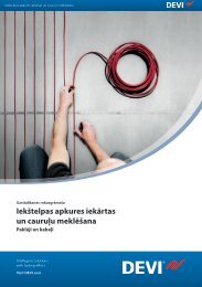
With regard to the reception conditions in the<br />
current holiday house it may in certain conditions<br />
be necessary to change to an alternative<br />
aerial and possibly an aerial extension cable<br />
(contact Support - see page 30). This aerial can<br />
be mounted either indoors and or outdoors.<br />
If your laptop <strong>com</strong>puter has no serial port<br />
input, use a serial-to-USB converter that can be<br />
ordered separately (contact Support - see page<br />
30).<br />
USB Converter<br />
Alternative aerial
step<br />
I n s t a l l a t i o n G u i d e - W E B · H O M E
WEB•HOME - Introduction<br />
Introduction<br />
WEB•HOME consists of the WEB•HOME<br />
unit, which is installed in the electrical cabinet<br />
in the holiday house, and via a GSM based modem<br />
<strong>com</strong>municates with a server that the owner<br />
of the holiday house can log on to via the Internet.<br />
The WEB•HOME unit can be connected<br />
to a network of Devireg 550 thermostats.<br />
WEB•HOME functions exclusively together<br />
with Devireg 550 thermostats.<br />
You can test and control whether the installation<br />
works in situ. DEVI has developed a configuration<br />
tool, devi<strong>com</strong> configurator, which provides<br />
assurance that WEB•HOME functions before<br />
you leave the holiday house. The tool contains<br />
a thorough check list that guides you systematically<br />
through the configuration tasks. This<br />
means that you afterwards can leave the holiday<br />
house with an easy mind, perfectly confident<br />
that WEB·HOME is functioning correctly.<br />
Installing WEB•HOME takes 4 steps that are<br />
described in detail on the following pages.<br />
Step 1: <strong>Installation</strong> of the required number of<br />
Devireg 550 thermostats in the holiday house.<br />
Step 2: <strong>Installation</strong> of the WEB•HOME unit<br />
and connections (e.g. thermostats, third party<br />
burglar alarm system and water heater).<br />
Step 3: Configuration of the WEB•HOME<br />
system using laptop pc.<br />
Step 4: Reading and passing on the customer’s<br />
user ID for logging on toWEB•HOME on the<br />
Internet.
I n s t a l l a t i o n G u i d e - W E B · H O M E <br />
Step 1: Install thermostats<br />
Re<strong>com</strong>mended placing of each thermostat<br />
step step<br />
• <strong>Installation</strong> height, typically between 80- 150 cm., when<br />
Devireg 550 is used as room sensor.<br />
• The thermostat must not be placed in places<br />
where it will be exposed to splashes of water<br />
or damp.<br />
step<br />
• Away from windows/doors that will be left open occasionally.<br />
step
WEB·HOME - Step 1<br />
• Not on a wall where it will be subjected to direct sunlight.<br />
• Not on a wall where it will be covered by curtains, towels<br />
etc. hanging in front of the thermostat.<br />
• Devireg 550 must not be installed in small rooms with<br />
insufficient ventilation, such as bathrooms. In these cases<br />
the thermostat must be placed outside the room and a floor<br />
sensor (FS) used instead.<br />
• Not on a wall facing the outside.
I n s t a l l a t i o n G u i d e - W E B · H O M E <br />
Install Devireg 550 thermostat<br />
1 2<br />
step step<br />
1 Remove the front cover by gently pressing<br />
the release tab in the top (center hole).<br />
2 Lift off the cover.<br />
3 Unscrew the two screws, one in each side.<br />
4 Gently pull off the display module.<br />
3 4<br />
step<br />
step<br />
5 Remove the frame from the thermostat.<br />
5
Step 1: Install thermostats<br />
6 Connect the thermostat.<br />
As Devireg 550 is not equipped with an<br />
earth terminal, the earth screen of the heating<br />
cable must be connected to the earth from the<br />
supply via the earth terminal in the surface<br />
mounted box or the recessed metal box which<br />
ever is used.<br />
Heating element<br />
Max. load 16 Amp.<br />
Mains supply<br />
180-250 V<br />
50/60 Hz<br />
Network<br />
connection<br />
NTC floor sensor<br />
Network<br />
connection<br />
NTC floor sensor
I n s t a l l a t i o n G u i d e - W E B · H O M E <br />
step step<br />
step<br />
step<br />
5 When installing the Devireg 550 you need<br />
to choose the type of heating and thus which<br />
sensors should be used.<br />
You have three options:<br />
Comfort heating: Constant temperature on<br />
the floor in bathrooms and other rooms that<br />
are often used with bare feet.<br />
Install the Floor sensor and choose only the<br />
Floor sensor in Basic Settings (see page 9).<br />
Total room heating: Control of room temperature<br />
in living rooms etc.<br />
Install the Floor sensor and choose both<br />
Floor sensor and Room sensor in Basic Settings<br />
(see page 9).<br />
No floor sensor: A floor sensor is not present,<br />
and cannot be installed.<br />
Choose Room sensor only in Basic Settings (see<br />
page 9).<br />
Be aware that temperature control is less<br />
accurate without the floor sensor. DEVI re<strong>com</strong>mend<br />
that a floor sensor is always installed.<br />
Do not use Devireg 550 without a floor<br />
sensor when the heating element is installed on<br />
or beneath wooden surfaces and other surfaces<br />
sensitive to temperature!
Step 1: Install thermostats<br />
6 You can now mount the thermostat on the<br />
wall using any of the eight screw holes in the<br />
base module.<br />
Screw holes<br />
When working on thermostats connected<br />
to a network, ensure the mains supply for all<br />
thermostats in the network is disconnected<br />
before work is started.<br />
7 Reassemble the thermostat by first replacing<br />
the frame, then mount the display module,<br />
and finally press the front cover into place.<br />
The display must be gently remounted on<br />
the base module, ensuring that the 8-pin plug<br />
is placed accurately by using the four tabs<br />
surrounding it.<br />
When inserting the two screws in the display<br />
module, please do not over tighten them.<br />
Do not over tighten!
I n s t a l l a t i o n G u i d e - W E B · H O M E <br />
step step<br />
Activate Devireg 550<br />
When the thermostat is connected to the mains<br />
for the first time, you must choose a code to get<br />
access to the basic settings. The word COdE will<br />
be displayed.<br />
1 Turn the button and keep turning until the<br />
code 0044 is shown.<br />
2 Press the button.<br />
step<br />
step
Step 1: Install thermostats<br />
3 Now select the sensors to be used for the<br />
heating system:<br />
Devireg 550 is able to use two sensors:<br />
• a built-in sensor<br />
• an external sensor to be placed in the floor.<br />
Turn the button to choose either<br />
• room sensor (rS),<br />
• floor sensor (FS),<br />
• or both room and floor sensors (rFS).<br />
4 Press the button when you have made your<br />
choice of sensor.<br />
If Devireg 550 only uses a floor sensor, the<br />
display will not show the actual temperature<br />
(5° to 35°), but a scale from 0 to 10.<br />
Always use a floor sensor when the heating<br />
element is installed on or beneath wooden<br />
surfaces!
I n s t a l l a t i o n G u i d e - W E B · H O M E <br />
step step<br />
Change basic settings<br />
Do as follows to change the basic setting of the<br />
thermostat:<br />
1 Press and hold the button for 12 seconds.<br />
Then the word COdE will be displayed.<br />
2 Turn the button to choose code.<br />
12 sec.<br />
step<br />
3 Turn until code 0044 is shown.<br />
4 Press the button.<br />
step<br />
10
Step 1: Install thermostats<br />
Now you have access to the menu of basic settings for the following items:<br />
Setting<br />
Type of network<br />
Temperature units<br />
Sensor<br />
Max. temperature<br />
Offset<br />
Timer (economy set-back)<br />
Hours<br />
Display<br />
<br />
<br />
<br />
<br />
<br />
<br />
<br />
<br />
<br />
<br />
<br />
<br />
<br />
<br />
<br />
<br />
<br />
<br />
<br />
<br />
<br />
<br />
<br />
ALO<br />
<br />
<br />
<br />
<br />
<br />
<br />
<br />
<br />
<br />
<br />
C<br />
OF FS<br />
L O<br />
<br />
<br />
24<br />
<br />
<br />
<br />
<br />
<br />
<br />
<br />
<br />
<br />
<br />
<br />
<br />
<br />
<br />
<br />
<br />
<br />
<br />
<br />
<br />
<br />
For each item you can choose a setting (by first turning and then pressing the button) or go on<br />
to the next item by pressing the button (accepting the current setting).<br />
11
I n s t a l l a t i o n G u i d e - W E B · H O M E <br />
step step<br />
step<br />
step<br />
Type of network<br />
The first thing to set up in the basic settings is<br />
whether the Devireg 550 must operate<br />
ALOne,<br />
as MASter thermostat,<br />
• or as a SLAve thermostat.<br />
All Devireg 550 thermostats in a building can<br />
be linked in a network enabling central adjustment<br />
of clock setting and other parameters. In<br />
a network only one of the thermostats can be set<br />
up as Master. Set up the slaves first. You can read<br />
more about networks on page 20. If you do not<br />
want to set up a network with master and slaves,<br />
you must select ALO.<br />
1 Turn the button to choose ALO, MAS or SLA.<br />
2 Press the button when you have made a<br />
choice.<br />
If you choose Slave, not all Basic Settings will<br />
appear. The settings left out can be set from the<br />
Master unit.<br />
Connection of the thermostat network to<br />
WEB•HOME later on does not require a network<br />
set-up with master and slave thermostats.<br />
12
Step 1: Install thermostats<br />
Temperature units<br />
Choose whether the thermostat uses Celsius (C)<br />
or Fahrenheit (F) to display temperature.<br />
1 Turn the button to choose C° or F°.<br />
2 Press the button when you have made your<br />
choice.<br />
13
I n s t a l l a t i o n G u i d e - W E B · H O M E <br />
step step<br />
step<br />
Sensor<br />
Now you must choose the sensor(s) to be used<br />
for this thermostat.<br />
Devireg 550 can use two sensors, a built-in<br />
room sensor and an external sensor, which can<br />
be placed in the floor, for instance.<br />
1 Turn the button to choose either<br />
• room sensor (rS),<br />
• floor sensor (FS)<br />
• or both room and floor sensor (rFS).<br />
2 Press the button when you have made your<br />
choice.<br />
If Devireg 550 only uses a floor sensor, the<br />
display will not show the current temperature<br />
(5° to 35°), but a value on a scale from 0 to 10.<br />
step<br />
14
Step 1: Install thermostats<br />
Maximum temperature<br />
Due to different floor constructions it is possible<br />
to choose a maximum floor temperature (Mt),<br />
which must not be exceeded. The temperature<br />
range is 20°C to 50°C.<br />
1 Turn the button until the required maximum<br />
floor temperature is shown.<br />
2 Press the button when you have made your<br />
choice.<br />
Maximum temperature setting for different floor<br />
constructions:<br />
Tiles on chipboard 30°C<br />
Carpet/vinyl on chipboard 35°C<br />
Wooden floors (parquet, plank, etc.) 30°C<br />
Other (concrete, screed, etc.) 45°C<br />
Maximum floor temperature is preset at the<br />
factory to 45°C for cable temperature safety.<br />
Local building regulations must be observed<br />
when changing the maximum preset temperature.<br />
For wooden floor constructions DEVI<br />
re<strong>com</strong>mend the temperature is limited to a<br />
maximum of 30°C.<br />
15
I n s t a l l a t i o n G u i d e - W E B · H O M E <br />
step step<br />
step<br />
Offset<br />
Offset (OFFS) can be used to <strong>com</strong>pensate for any<br />
difference between the thermostat and a room<br />
thermometer.<br />
If the thermometer, for instance, shows 1°C<br />
more than the thermostat, it is possible to adjust<br />
the offset by +1°C. Then the thermostat will<br />
show the same temperature as the thermometer.<br />
The range is -5.5°C to +5.5°C.<br />
1 Turn the button until the wanted adjustment<br />
of offset is displayed.<br />
2 Press the button when you have made your<br />
choice.<br />
step<br />
16
Step 1: Install thermostats<br />
Use of timer<br />
Using the built-in timer, the thermostat can be<br />
programmed to lower the temperature (LO), for<br />
example during the night.<br />
The range is 0°C to -30°C.<br />
For example, choose -5°C if the temperature<br />
should be lowered by 5 degrees.<br />
1 Turn the button to choose economy set-back<br />
level.<br />
2 Press the button when you have made your<br />
choice.<br />
If normal room heating is installed we re<strong>com</strong>mend<br />
not lowering the temperature at night by<br />
more than about -5°C.<br />
17
I n s t a l l a t i o n G u i d e - W E B · H O M E <br />
step<br />
step<br />
12 hour (AM/PM) or 24 hour clock<br />
Finally, the type of clock can be set. Choose 24<br />
or 12 hour clock<br />
1 Turn the button to choose 12 or 24 hours.<br />
2 Press the button when you have made your<br />
choice.<br />
This <strong>com</strong>pletes the basic settings, and the display<br />
will return to the daily operation menu.<br />
step<br />
Regarding how to set the clock and timer,<br />
please refer to the user’s guide to Devireg 550<br />
thermostat.<br />
step<br />
18
Step 1: Install thermostats<br />
Factory settings<br />
The thermostat is preset with the following parameters:<br />
Operation Factory setting Options<br />
Type of network Alone Alone, Master or Slave<br />
Temperature units C° C° or F°<br />
Sensor Room and floor sensor rFS) Room sensor (rS), floor sensor (FS) or<br />
room and floor sensor (rFS)<br />
Max. temperature +45°C +20°C to +50°C<br />
Offset 0.0°C -5,5°C to +5,5°C<br />
Timer -5°C 0° to -30°C<br />
Day of week 1 1, 2, 3, 4, 5, 6, 7<br />
Hours 24 12 hours AM/PM or 24 hours<br />
Time --:-- --:--<br />
Timer settings - Up to 336/week<br />
19
I n s t a l l a t i o n G u i d e - W E B · H O M E <br />
step<br />
step<br />
step<br />
step<br />
Network connections<br />
The Devireg 550 features a network capability.<br />
All Devireg 550’s installed in a building can be<br />
linked together via the network facility, allowing<br />
central adjustment of programming and parameters,<br />
for example clock setting.<br />
The network can include up to 32 units, i.e. 1<br />
master and up to 31 slave units.<br />
It is only possible to have one master unit.<br />
A Devireg 550 can be set as a stand-alone unit,<br />
even though it is connected to the network. It<br />
will not respond to or send information to a<br />
master unit, but it will count as one of the maximum<br />
of 32 units in the network.<br />
The network is a separate two wire net, where<br />
the cables are unshielded, untwisted and unpolarised<br />
for easy installation. The maximum<br />
length of the network cables is 500 metres.<br />
If more master units are configured on the network,<br />
an error message will flash in the display,<br />
and the unit will need to be re-configured.<br />
If a Devireg 550 is configured as a slave unit,<br />
the following set-up parameters are controlled<br />
from the master unit:<br />
• Time<br />
• Day of week<br />
• C° or F°<br />
• 12 or 24 hour clock<br />
• Timer program<br />
Network accessories:<br />
Network cable, single core 0,75 mm² (100 m).<br />
At long distances, use 1,5 mm2 cable.<br />
Contact Support - see page 30.<br />
20
Step 1: Install thermostats<br />
Error messages<br />
Devireg 550 has a built-in system that constantly<br />
checks the heating system, the thermostat itself<br />
and a possible network for any malfunctions.<br />
If an error occurs, the display will flash together<br />
with a code for the detected fault, which will be<br />
shown as a number from 1 to 7.<br />
To do a reset after an error message, enter the<br />
basic settings and go through all items (see<br />
page 10).<br />
No Error<br />
A fault on the floor sensor/sensor cable or<br />
thermostat overheating will result in the heating<br />
being switched off.<br />
.<br />
What to do<br />
2 Configured as Master, but another Master<br />
unit detected.<br />
3 Configured as a Slave, but cannot find any<br />
Master unit.<br />
4 The thermostat is switched off because of<br />
overheating.<br />
Only one unit may be configured as a Master<br />
One unit must be configured as Master.<br />
Let the thermostat cool for a period.<br />
Then enter basic set-up to leave error mode.<br />
5 Sensor fault. Floor sensor short-circuit. Change the floor sensor.<br />
6 Sensor fault. Floor sensor open circuit. Change the floor sensor.<br />
7 Clock is not set. Set the clock<br />
21
I n s t a l l a t i o n G u i d e - W E B · H O M E <br />
Technical specifications for Devireg 550 thermostat<br />
step step<br />
step<br />
Temperature range +5° to +35°C or OFF<br />
Floor temperature limit +20° to +50°C<br />
Voltage<br />
180 - 250 V ~ 50/60 Hz<br />
Resistive load<br />
250 V ~ 16 A<br />
Inductive load<br />
cos ϕ = 0.3 Max. 1 A<br />
Power consumption < 500 mW<br />
Battery backup<br />
100 hours<br />
Economy set-back 0° to -30°C<br />
Offset -5<br />
IP class IP 30<br />
Type of sensor<br />
NTC floor sensor<br />
Sensor value<br />
15 kOhm/25°C<br />
step<br />
22
Step 1: Install thermostats<br />
Devireg 550 connection diagram<br />
NTC floor sensor<br />
Network<br />
connection<br />
23
I n s t a l l a t i o n G u i d e - W E B · H O M E <br />
Step 2: Install WEB·HOME unit<br />
step step<br />
Connect power supply<br />
The power supply to WEB•HOME consists<br />
of a 24V unit that must be connected to the<br />
WEB•HOME unit.<br />
Connect the power supply to the terminal points<br />
13 and 14 on the WEB•HOMEunit.<br />
Please ensure correct polarity.<br />
step<br />
step<br />
To thermostat<br />
24
WEB·HOME - Step 3<br />
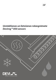
Connect aerial<br />
The aerial for WEB•HOME consists of<br />
two parts: a plug that is inserted in the<br />
WEB•HOME unit, and the aerial itself with<br />
cable and magnet base.<br />
The aerial with magnet base must only be<br />
used indoors.<br />
1 Connect the two aerial parts.<br />
2 Plug the aerial connector firmly into the<br />
aerial socket on the WEB•HOME unit.<br />
3 Place the magnet base of the aerial in an appropriate<br />
position.<br />
Re<strong>com</strong>mendations for placing the aerial:<br />
• It must be placed away from the electrical<br />
cabinet.<br />
• The aerial must not ’lean’ against metal.<br />
• Move, if necessary, the aerial higher up in the<br />
house.<br />
Press hard !<br />
25
I n s t a l l a t i o n G u i d e - W E B · H O M E <br />
step step<br />
step<br />
step<br />
Connect aerial<br />
Later on during the installation when you<br />
configure WEB•HOME using the devi<strong>com</strong><br />
configurator (read more in step 3), you must test<br />
the reception conditions on site and determine<br />
whether the aerial should be placed somewhere<br />
else to achieve optimum reception. To improve<br />
reception it is most important to follow the<br />
re<strong>com</strong>mendations for placing the aerial (see<br />
previous page).<br />
In certain conditions it may be necessary to<br />
change to an alternative aerial and possibly an<br />
aerial extension cable (contact Support - see<br />
page 30). This aerial can be mounted either<br />
indoors and or outdoors.<br />
If you use an alternative aerial, it must be attached<br />
to the aerial socket of the WEB•HOME<br />
unit.<br />
26
Step 2: Install WEB·HOME unit<br />
Connect Devireg 550 thermostats<br />
Connect one of the linked Devireg 550 thermostats<br />
to WEB•HOME by connecting to devinet<br />
(terminals 11 and 12) on the WEB•HOME<br />
unit.<br />
Minimum thickness of cable used for wiring<br />
and connecting thermostats is 0,75 mm2.<br />
A maximum of 31 linked Devireg 550 thermostats<br />
can be connected to WEB•HOME.<br />
NTC floor sensor<br />
Network connection<br />
27
I n s t a l l a t i o n G u i d e - W E B · H O M E <br />
step step<br />
Using relay output<br />
The relay output on the WEB•HOME unit can<br />
for example be used to control a water heater.<br />
Connect the unit (e.g. water heater) to terminals<br />
1 and 2 on the WEB•HOME unit.<br />
For safety you must not connect anything to<br />
the relay output, which in any way may present<br />
a danger, for instance by lighting a fire (towel on<br />
radiator without overheating cut-out), switching<br />
on devices (e.g. oven in sauna where towels may<br />
be lying about), etc.<br />
Max. 2A<br />
WEB·HOME<br />
step<br />
step<br />
Example: water heater<br />
28
Step 2: Install WEB·HOME unit<br />
Using input<br />
The input on the WEB•HOME unit can be<br />
used for connecting a temperature sensor or for<br />
instance a burglar alarm.<br />
When you (at a later stage) configure<br />
WEB•HOME (using Devi<strong>com</strong> configurator)<br />
and the input, you can choose between a temperature<br />
sensor or digital input (see page 43).<br />
If the input is a temperature sensor, choose<br />
Temperature sensor during the configuration.<br />
You may connect the DEVI standard thermostat<br />
floor sensor with 3 metres of cable (contact Support<br />
- see page 30) as the temperature sensor to<br />
the input. If the input is a burglar alarm (on/off<br />
input), choose Digital input during the configuration.<br />
Connect temperature sensor, burglar alarm, or<br />
other user device to terminals 7 and 8 on the<br />
WEB•HOME unit.<br />
29
I n s t a l l a t i o n G u i d e - W E B · H O M E <br />
step step<br />
step<br />
step<br />
Support<br />
If you need support for WEB•HOME, please<br />
contact:<br />
DEVI A/S, Sales Denmark<br />
Boedkervej 8, Vinding<br />
DK-7100 Vejle<br />
Phone: +45 75 85 85 85<br />
E-mail: mail@devi.dk<br />
Extra possibilities for connections to<br />
WEB•HOME<br />
There are other possibilities for making connections<br />
and extensions to WEB•HOME. Read<br />
more in Extra Possibilities for Connections to<br />
WEB•HOME.<br />
Battery back-up in WEB•HOME The<br />
WEB•HOME unit has been provided with<br />
battery back-up, so the customer will be notified<br />
- also in case the power fails.<br />
The backup battery in WEB•HOME has<br />
only been designed for ‘emergency calls’ relating<br />
to WEB•HOME (e.g. about power failure).<br />
Thus, it will not work after the ‘emergency<br />
call’ has been made, and therefore not inform<br />
customers about any errors from external<br />
equipment that may have been connected to<br />
WEB•HOME (e.g. burglar alarm) either.<br />
SIM card<br />
The SIM card in the WEB•HOMEunit<br />
is locked to the unit and can not be used for<br />
mobile telephony.<br />
30
Step 2: Install WEB·HOME unit<br />
Technical specifications for<br />
WEB•HOME unit<br />
Power consumption<br />
Relay:<br />
- Resistive load<br />
- Inductive load<br />
Max. 3 W<br />
IP class IP20<br />
Surrounding temperature<br />
Indicator<br />
Size<br />
250V ~ 2A<br />
1A (power factor 0,3)<br />
-10°C to +40°C<br />
2x16 character display<br />
with backlight.<br />
D/H/W<br />
53x86x105mm<br />
Technical specifications for<br />
power supply<br />
Input voltage 230 VAC +10%/-20%<br />
Output voltage<br />
Output power<br />
IP class:<br />
Surrounding temperature<br />
Size<br />
24 VDC<br />
24 W<br />
IP20<br />
-10°C til +40°C<br />
D/H/W<br />
53x86x70mm<br />
31
I n s t a l l a t i o n G u i d e - W E B · H O M E <br />
Step 3: Configure WEB·HOME<br />
step<br />
step<br />
step step<br />
Connect laptop <strong>com</strong>puter to WEB•HOME<br />
1 Switch off your laptop <strong>com</strong>puter and the<br />
WEB•HOME unit.<br />
2 Insert <strong>com</strong>puter cable into the <strong>com</strong>puter<br />
socket on the WEB•HOME unit.<br />
3 Insert <strong>com</strong>puter cable into serial port input<br />
on the laptop <strong>com</strong>puter.<br />
If your laptop <strong>com</strong>puter has no serial port<br />
input, use a serial-to-USB converter that can be<br />
ordered separately (contact Support - see page<br />
30).<br />
32
WEB·HOME - Step 3<br />
Install Devi<strong>com</strong> configurator on <strong>com</strong>puter<br />
1 Turn on the laptop <strong>com</strong>puter.<br />
2 Insert the CD-ROM with the Devi<strong>com</strong> configurator<br />
for WEB•HOME in the CD-ROM<br />
drive.<br />
Now the Devi<strong>com</strong> configuratur setup program<br />
will automatically start. After a while<br />
the Wel<strong>com</strong>e window will be shown.<br />
If the Microsoft .NET Framework 1.1<br />
Package is not available on your <strong>com</strong>puter,<br />
the setup program will automatically ensure<br />
that it is installed prior to the installation of<br />
the Devi<strong>com</strong> configurator.<br />
3 Click Next.<br />
33
I n s t a l l a t i o n G u i d e - W E B · H O M E <br />
4 Optionally specify a different folder for the<br />
Devi<strong>com</strong> configurator program.<br />
step<br />
step<br />
step step<br />
You can also decide if only you (Just me) shall<br />
have access to the program, or whether it<br />
should be available to all (Everyone).<br />
Click Next.<br />
5 Click Next to begin the installation of<br />
Devi<strong>com</strong> configurator on the <strong>com</strong>puter.<br />
34
Step 3: Configure WEB·HOME<br />
6 When the installation is <strong>com</strong>plete you will<br />
receive a message telling you that the installation<br />
has finished.<br />
Click Close.<br />
A shortcut to the Devi<strong>com</strong> configurator<br />
will automatically be placed on the <strong>com</strong>puter<br />
desktop.<br />
35
I n s t a l l a t i o n G u i d e - W E B · H O M E <br />
step<br />
step<br />
step step<br />
Open Devi<strong>com</strong> configurator<br />
Click the Devi<strong>com</strong> configurator icon on the<br />
desktop.<br />
Then the Devi<strong>com</strong> configurator window will be<br />
displayed<br />
Choose a language for Devi<strong>com</strong> configurator<br />
If you want to use the configuration program<br />
in another language, click the flag and select a<br />
language.<br />
Begin configuration of WEB•HOME<br />
Click Open.<br />
36
Step 3: Configure WEB·HOME<br />
The Devi<strong>com</strong> WEB•HOME window<br />
where you can configure the current<br />
WEB•HOMEinstallation will be shown.<br />
In the left part you can navigate among the various<br />
units connected to WEB•HOME.<br />
You can click the plus/minus signs to open/close<br />
various parts of units.<br />
The right part of the window shows your choice<br />
in the navigation part, i.e. it will show information<br />
about the unit you have clicked on in the<br />
navigation part.<br />
The bottom part shows a task list with all the<br />
tasks required to perform configuration of<br />
WEB•HOME.<br />
37
I n s t a l l a t i o n G u i d e - W E B · H O M E <br />
step<br />
step<br />
step step<br />
Enter house name<br />
1 Click WEB•HOME in the navigation part.<br />
The Name of the house field shows a<br />
number signifying the ID of the current<br />
WEB•HOME unit.<br />
2 Delete the ID number in the Name of the<br />
house field and enter instead the name<br />
of the holiday house with the current<br />
WEB•HOME installation.<br />
3 Click Save.<br />
38
Step 3: Configure WEB·HOME<br />
Enter thermostat names<br />
1 Below Devireg 550 system in the navigation<br />
part all thermostat units that have been<br />
connected to the WEB•HOME unit in the<br />
house will be displayed. Each thermostat is<br />
represented by a unique ID<br />
Check the number of thermostats in the<br />
list is the same as the number of Devireg 550<br />
thermostats installed in the house. Any thermostats<br />
that have not been linked to the network<br />
of thermostats connected to WEB•HOME will<br />
not appear on the list<br />
39
I n s t a l l a t i o n G u i d e - W E B · H O M E <br />
step<br />
step<br />
step step<br />
2 Before you can name a thermostat you first<br />
need to find the thermostat in the house.<br />
Go to the thermostat that you want to name<br />
and turn it off.<br />
In order to turn it off, the timer must be deactivated,<br />
i.e. the clock icon should not be<br />
displayed. You can turn the timer on/off by<br />
pressing thermostat button.<br />
Now keep turning the button to the left until<br />
it says OFF on the display. Then the thermostat<br />
has been de-activated, and in the list of<br />
thermostats in Devi<strong>com</strong> configurator it will<br />
be marked with a yellow question mark.<br />
3 Click thermostat with the yellow question<br />
mark.<br />
4 Type in a memorable name (e.g. the name<br />
of the room where the thermostat has been<br />
installed) in the Description field.<br />
If you disable the thermostat (it is by default<br />
enabled) by removing the check mark in the<br />
Enabled field, it will not be visible and accessable<br />
to the customer logging on WEB•HOME on<br />
the Internet.<br />
40
Step 3: Configure WEB·HOME<br />
The Information area shows various pieces<br />
of information about the selected thermostat,<br />
for instance status and devinet quality (for<br />
trouble shooting) and the temperature in the<br />
room where the thermostat is installed.<br />
5 To get more information about a thermostat<br />
(e.g. its unique ID and version), click the<br />
Information button. Then a window with<br />
device information is shown.<br />
6 Finally, click Save to save your entry. The<br />
name of the thermostat that you have typed<br />
in will be displayed in the navigation part,<br />
where it will have a green marking.<br />
7 Do not forget to go back to the thermostat<br />
and re-activate the timer and thermostat.<br />
Continue naming thermostats on the list in the<br />
Devi<strong>com</strong> configurator by repeating steps 1-7.<br />
When you finished naming all thermostats the<br />
task will be marked as done on the task list in<br />
the bottom part of the window.<br />
41
I n s t a l l a t i o n G u i d e - W E B · H O M E <br />
step<br />
step<br />
step step<br />
Enable and name Auxiliary input<br />
1 Go to Auxiliary input/output.<br />
2 Click Temperature sensor.<br />
Then the corresponding tab is displayed to<br />
the right.<br />
3 Enable the temperature sensor by setting a<br />
check mark in the Enabled field.<br />
4 Type in a description of the temperature<br />
sensor in the Description field.<br />
5 Now you can click Save to save your entries<br />
or continue to set alarm settings for the input<br />
unit (refer to next page).<br />
42
Step 3: Configure WEB·HOME<br />
Select sensor type<br />
When selecting alarm settings for the input unit,<br />
you must first set the sensor type:<br />
• Digital input (On/Off), for example a thirdparty<br />
burglar alarm.<br />
• Temperature sensor (analog) or measuring<br />
temperature (e.g. with DEVI standard thermostat<br />
floor sensor).<br />
43
I n s t a l l a t i o n G u i d e - W E B · H O M E <br />
step<br />
step<br />
step step<br />
Alarm settings for temperature sensor<br />
1 Select Temperature sensor in Input settings.<br />
2 Choose one of the following alarm settings:<br />
• Disabled, no alarms will be sent.<br />
• Send alarm if input value LESS than the<br />
specified alarm limit.<br />
• Send alarm if input value GREATER than<br />
the specified alarm limit.<br />
3 Enter a numerical value in the Alarm limit<br />
field.<br />
4 Click Save.<br />
44
Step 3: Configure WEB·HOME<br />
Alarm settings for digital input<br />
1 Select Digital input in Input settings.<br />
2 Choose one of the following alarm settings:<br />
• Disabled, no alarms will be sent.<br />
• Send alarm if input changes from LOW<br />
to HIGH (when the input is broken).<br />
• Send alarm if input changes from HIGH<br />
to LOW (when the input short-circuits).<br />
3 Click Save.<br />
45
I n s t a l l a t i o n G u i d e - W E B · H O M E <br />
step<br />
step<br />
step step<br />
Enable and name auxiliary output (relay)<br />
1 Click Relay output. The corresponding tab is<br />
displayed to the right.<br />
2 Enable the output by setting a check mark in<br />
the Enabled field.<br />
3 Type in a description of the relay device in<br />
the Description field.<br />
You can test that the relay output works<br />
correctly by:<br />
• Turning relay output on by selecting Relay<br />
ON.<br />
• Turning relay output off by selecting Relay<br />
OFF.<br />
4 Click Save.<br />
46
Step 3: Configure WEB·HOME<br />
Ensure good signal quality<br />
Click WEB•HOME in the navigation part.<br />
The signal quality will be shown to the right.<br />
Below GSM network registration / signal quality<br />
you can at any time see the current signal quality.<br />
• If in the red area, there is insufficient signal,<br />
and you have to increase the signal by changing<br />
the position of the aerial (refer to next page).<br />
• If in the yellow area, there is a risk of outages,<br />
and we re<strong>com</strong>mend that you try to improve the<br />
quality by changing the position of the aerial<br />
(refer to next page).<br />
• If in the green area, the quality is fine, and<br />
there is no need for adjustment.<br />
47
I n s t a l l a t i o n G u i d e - W E B · H O M E <br />
step<br />
step<br />
step step<br />
Improve signal quality<br />
To improve the signal quality, do as follows:<br />
1 Follow the re<strong>com</strong>mendations for placing the<br />
magnetic aerial:<br />
• It must be placed away from the electrical<br />
cabinet.<br />
• The aerial must not ’lean’ against metal.<br />
2 If this does not improve signal quality, move,<br />
if necessary, the aerial higher up (in the<br />
house).<br />
3 If this does not improve signal quality, it may<br />
under certain circumstances be necessary<br />
to change to an alternative aerial and maybe<br />
antenna extension cable (contact Support<br />
- see page 30).<br />
The alternative aerial can be used both indoors<br />
and outdoors.<br />
If you mount the alternative aerial, it must be<br />
attached to the aerial connection part for the<br />
WEB•HOME unit (refer to page 25-26).<br />
If, contrary to expectations, you do not succeed<br />
in getting a satisfactory signal quality, please<br />
contact DEVI Support (refer to page 303).<br />
48
Step 3: Configure WEB·HOME<br />
Test connection to the server<br />
The last task on the task list is to test the connection<br />
to the server.<br />
1 Click WEB HOME in the navigation part.<br />
2 Click the Test connection to the server<br />
button.<br />
Then a series of messages will be displayed in<br />
the Status area with Dialing up to the server<br />
being the first.<br />
3 After some time the Information window<br />
telling you that <strong>com</strong>munication with the<br />
server succeeded, will be displayed<br />
4 Click OK.<br />
Finally the message Ready will appear in<br />
Status area.<br />
49
I n s t a l l a t i o n G u i d e - W E B · H O M E <br />
step<br />
step<br />
step step<br />
Colour markings of thermostats<br />
When thermostats are shown in the Devi<strong>com</strong><br />
configurator below Devireg 550 system in the<br />
navigation part, they may have different icons<br />
and colour markings signifying various things<br />
(see below). If you want to know more about a<br />
thermostat, click its name/ID in the navigation<br />
part and look at the detailed information to the<br />
right of the window.<br />
• Grey marking: The thermostat has been disabled<br />
in the Devi<strong>com</strong> configurator.<br />
• Green triangle: The thermostat is okay.<br />
• Yellow question mark: The thermostat has<br />
been turned off.<br />
Kitchen<br />
Bedroom<br />
17435<br />
Sitting room<br />
Child’s room<br />
50
Trin 3: Konfigurere WEB·HOME<br />
• Blue exclamation mark: Error on thermostat.<br />
Example: The thermostat is of an older version<br />
(older than version 6.02), which is not<br />
supported by WEB•HOME.<br />
Solution: Change thermostat into a newer<br />
version.<br />
The error may also be due to the thermostat<br />
being set up as a ’slave’, without another thermostat<br />
being defined as ’master’.<br />
Solution: Change the setting of thermostat<br />
into ’alone’ or define another thermostat as<br />
‘master’ (refer to page 20).<br />
• Red cross: WEB•HOME cannot <strong>com</strong>municate<br />
with the thermostat, e.g. because it is<br />
defective.<br />
Solution: Check both the cable connected to<br />
the thermostat and the thermostat itself.<br />
51
I n s t a l l a t i o n G u i d e - W E B · H O M E <br />
Step 4: Read and pass on customer’s user ID<br />
step<br />
step<br />
step step<br />
Read and pass on customer’s user ID<br />
When you have performed steps 1-3, and the installation<br />
of WEB•HOME has been finished<br />
and functions correctly, you must finally read<br />
the customer’s user ID, consisting of six<br />
digits, on the WEB•HOME unit.<br />
The customer needs to have this user ID<br />
in order to be able to make the first logon<br />
to WEB•HOME on the Internet.<br />
1 Press and hold the i button to the top right<br />
of the unit. A number will be displayed.<br />
2 Type the number from the User ID field<br />
on the back cover of the User’s <strong>Guide</strong> to<br />
WEB•HOME.<br />
3 Put the User’s <strong>Guide</strong> to WEB•HOME in an<br />
envelope and post the letter to the customer.<br />
4 Fill in the guarantee certificate, too.<br />
The ID is also printed on rear side of the unit.<br />
52
T h e D E V I W a r r a n t y<br />
W a r r a n t y C e r t i f i c a t e<br />
WEB·HOME - Step 4<br />
You have purchased WEB•HOME, which forms an integrated<br />
part of a deviheat system, which we are certain will improve your<br />
home <strong>com</strong>fort and economy. Deviheat provides <strong>com</strong>plete heating<br />
solutions with deviflex heating cables or devimat heating mats,<br />
devireg thermostats and devifast fitting bands.<br />
If, however, contrary to all expectations, a problem should occur<br />
with your Devireg heating system, we at DEVI, with manufacturing<br />
units in Denmark, are, as European Union suppliers, subject<br />
to general product liability rules, as stated in Directive 85/374/CEE,<br />
and all relevant national laws which implies that:<br />
DEVI provides a warranty for deviflex heating cables and<br />
devimat heating mats for a 10 year period and all other DEVI<br />
products for a 2 year period against defects in material and production.<br />
The guarantee is granted on the condition that the Warranty<br />
Certificate on the overleaf is filled out properly in accordance to<br />
instructions and that the defect is inspected by, or presented to,<br />
DEVI or authorised DEVI distributor.<br />
Please note that the wording of the Warranty Certificate must be<br />
provided in English or local language with the ISO code for your<br />
country in the upper left corner of the front page of the installation<br />
instructions in order to release the warranty.<br />
The obligation of DEVI will be to repair or supply a new unit, free<br />
of charge to the customer, without secondary charges linked to repairing<br />
the unit. In case of defective devireg thermostats, DEVI<br />
reserves the right to repair the unit free of charge and without<br />
unreasonable delay to the customer.<br />
The DEVI warranty does not cover installations made by<br />
unauthorised electricians, or faults caused by incorrect designs<br />
supplied by others, misuse, damage caused by others, or incorrect<br />
installation or any subsequent damage that may occur. If DEVI<br />
is required to inspect or repair any defects caused by any of the<br />
above, then all work will be fully chargeable.<br />
The DEVI warranty is void, if payment of the equipment is in<br />
default. At all times, we at DEVIwill respond honestly, efficiently<br />
and promptly to all queries and reasonable requests from our customers.<br />
The above mentioned warranty concerns product liability<br />
whereas matters in relation to legislation on sale of goods shall be<br />
referred to national law.<br />
Name:________________________________________________<br />
Address:______________________________________________<br />
Postal code:___________________________________________<br />
Phone:_______________________________________________<br />
Please note:<br />
In order to obtain the DEVI Warranty, the following<br />
must be carefully filled in!<br />
I n s t a l l a t i o n G u i d e - W E B · H O M E <br />
Index<br />
A<br />
activate thermostat 8<br />
aerial, alternative 26, 46<br />
aerial, connect to WEB•HOME 25<br />
aerial, placing 48<br />
aerial, signal quality 47<br />
alarm, connect to WEB•HOME 8<br />
alarm settings 45<br />
for digital input 45<br />
for temperature sensor 44<br />
alone, thermostat 9<br />
AM/PM, clock 18<br />
B<br />
battery backup 30<br />
burglar alarm 29<br />
C<br />
CD-ROM 33<br />
Celcius, temperature unit 13<br />
check list for configuration 37<br />
for configuration 1<br />
clock, AM/PM 18<br />
code, thermostat 10<br />
<strong>com</strong>puter, connect 32<br />
configurator, install 33<br />
connect<br />
aerial 25<br />
burglar alarm 8<br />
laptop <strong>com</strong>puter 32<br />
power supply 24<br />
temperature sensor 8<br />
thermostat 5<br />
connection diagram<br />
thermostat 21, 23<br />
WEB•HOME 24<br />
D<br />
Devi<strong>com</strong> configurator<br />
icon 36<br />
install 33<br />
open 36<br />
select language 36<br />
54
Index<br />
digital input 43, 45<br />
E<br />
economy set-back 17<br />
error messages, thermostat 21<br />
F<br />
factory settings, thermostat 19<br />
Fahrenheit, temperature unit 13<br />
floor sensor 6, 9, 14<br />
floor temperature, maximum 15<br />
I<br />
ID<br />
for logon on Internet 52<br />
on WEB•HOME unit 52<br />
information about thermostat 41<br />
input unit 29<br />
name 42<br />
install<br />
M<br />
configurator 33<br />
thermostat 4<br />
WEB•HOME unit 24<br />
master, thermostat 9, 20<br />
maximum floor temperature 15<br />
Microsoft .NET Framework 1.1.<br />
Package 33<br />
N<br />
name<br />
house 38<br />
input 41<br />
input unit 42<br />
output (relay) 46<br />
thermostat 39<br />
network connections 20<br />
network type, thermostat 9<br />
O<br />
offset, adjust on thermostat 16<br />
P<br />
power supply<br />
technical specifications 30<br />
power supply to WEB•HOME<br />
connect 24<br />
55
I n s t a l l a t i o n G u i d e - W E B · H O M E <br />
R<br />
read user ID 52<br />
re<strong>com</strong>mendations<br />
placing of aerial 48<br />
placing of thermostat 1<br />
relay unit 28<br />
name 46<br />
name and enable 46<br />
test 46<br />
room sensor 6, 9<br />
S<br />
sensor<br />
select 9, 14<br />
sensor type 6<br />
server, test connection 49<br />
signal quality 47, 48<br />
SIM card 30<br />
slave, thermostat 9, 20<br />
support 30<br />
T<br />
task list<br />
for configuration 37<br />
technical specifications<br />
power supply 30<br />
thermostat 22<br />
WEBHOME unit 31<br />
WEB•HOME unit 30<br />
temperature, lower using timer 17<br />
temperature, maximum floor 15<br />
temperature sensor 29, 43<br />
alarm settings 44<br />
name and enable 42<br />
temperature sensor, connect to<br />
WEB•HOME 8<br />
temperature units<br />
Celcius/Fahrenheit 13<br />
termostat<br />
turn off 40<br />
test connection to server 49<br />
thermostat<br />
activate 8<br />
basic settings 10, 11<br />
colour markings in configurator<br />
56
Index<br />
50<br />
connection diagram 23<br />
connect to WEB•HOME 27<br />
errors in configurator 50<br />
error messages 21<br />
factory settings 18, 19<br />
icons 50<br />
information about 41<br />
install 4<br />
master, slave or alone 9<br />
name 39<br />
network with master and slaves<br />
20<br />
re<strong>com</strong>mended placing 1<br />
technical specifications 21, 22<br />
version 50<br />
U<br />
USB converter 46<br />
W<br />
warranty, WEB•HOME 53<br />
water heater 28<br />
WEB•HOME<br />
warranty 53<br />
WEB•HOME unit<br />
technical specifications 31<br />
57
I n s t a l l a t i o n G u i d e - W E B · H O M E <br />
Notes: