Engineering Design Standards (PDF) - City of Southfield
Engineering Design Standards (PDF) - City of Southfield
Engineering Design Standards (PDF) - City of Southfield

You also want an ePaper? Increase the reach of your titles
YUMPU automatically turns print PDFs into web optimized ePapers that Google loves.
CITY OF SOUTHFIELD<br />
DEPARTMENT OF PUBLIC WORKS<br />
ENGINEERING DIVISION<br />
ENGINEERING DESIGN STANDARDS<br />
APPROVED BY:<br />
Gary M. Mekjian, P.E.<br />
<strong>City</strong> <strong>of</strong> <strong>Southfield</strong><br />
Director <strong>of</strong> Public Works<br />
Dated: Oct. 1, 2007<br />
Revised:<br />
<strong>Engineering</strong> Division<br />
<strong>City</strong> <strong>of</strong> <strong>Southfield</strong><br />
26000 Evergreen Road<br />
<strong>Southfield</strong>, MI 48037-2055<br />
Phone: (248) 796-4810
A note from the Director <strong>of</strong> Public Works:<br />
Welcome to the <strong>City</strong> <strong>of</strong> <strong>Southfield</strong>! We are very pleased that you and your organization<br />
are considering a real estate development within our fine city. In order to assist you in<br />
your efforts, the <strong>Engineering</strong> Division <strong>of</strong> the Department <strong>of</strong> Public Works is proud to<br />
provide you with this manual. It is the intent <strong>of</strong> our <strong>Engineering</strong> <strong>Design</strong> <strong>Standards</strong><br />
Manual to provide a clear, concise, and easy to follow guide on the procedures,<br />
processes, standards and fees associated with your construction project. Of course, if you<br />
have any questions, our highly pr<strong>of</strong>essional and well trained staff are always available to<br />
work with you to address your issues.<br />
We hope that you find this information useful and easy to follow, and once again, thank<br />
you for doing business in the <strong>City</strong> <strong>of</strong> <strong>Southfield</strong>!!<br />
Sincerely,<br />
Gary M. Mekjian, P.E.<br />
Director <strong>of</strong> Public Works<br />
/Forms/Site Plan <strong>Design</strong> <strong>Standards</strong> 10-01-07 Revision)<br />
Page 2 <strong>of</strong> 28
INTRODUCTION<br />
The following design standards are intended to provide a basis upon which all<br />
commercial, industrial and multiple sites within the <strong>City</strong> <strong>of</strong> <strong>Southfield</strong> are to be designed.<br />
The requirements outlined herein reflect the requirements <strong>of</strong> the <strong>Engineering</strong> Division <strong>of</strong><br />
the Department <strong>of</strong> Public Services and conform to current engineering practices in the<br />
Metropolitan Detroit area. The review <strong>of</strong> the submitted plans will be done by the <strong>City</strong><br />
Engineer, indicated herein, or his designee. By no means are these standards intended as<br />
a substitute for sound pr<strong>of</strong>essional engineering judgment. It is suggested that the<br />
applicant obtain a copy <strong>of</strong> the <strong>City</strong> <strong>of</strong> <strong>Southfield</strong> Zoning Ordinance to supplement these<br />
standards.<br />
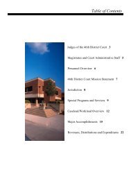
CONTENTS<br />
I. GENERAL REQUIREMENTS AND PROCEDURES 4<br />
II. SURVEY 13<br />
III. SOIL EROSION AND SEDIMENTATION CONTROL 14<br />
IV. WATER MAIN 15<br />
V. SANITARY SEWER 17<br />
VI. STORM SEWER 20<br />
VII. PAVING AND GRADING 23<br />
VIII. REQUIREMENTS FOR CITY ACCEPTANCE OF UTILITIES 27<br />
IX. SOUTHFIELD STANDARD NOTES 28<br />
/Forms/Site Plan <strong>Design</strong> <strong>Standards</strong> 10-01-07 Revision)<br />
Page 3 <strong>of</strong> 28
I. GENERAL REQUIREMENTS AND PROCEDURES<br />
A. GENERAL SUBMITTAL PROCEDURES:<br />
1. Prior to the issuance <strong>of</strong> a building permit, the plans must first receive<br />
an approval from the <strong>Engineering</strong> and Planning Divisions.<br />
2. A minimum <strong>of</strong> FOUR complete sets <strong>of</strong> civil site construction plans will<br />
be required, depending on the various agencies influenced by the<br />
proposed development. It is recommended that the applicant meet with<br />
the <strong>Engineering</strong> Division prior to submittal <strong>of</strong> any plans. The plans<br />
will be received at the <strong>Engineering</strong> Division Office, 26000 Evergreen<br />
Road, <strong>Southfield</strong>. All plans must be sealed by an Engineer or Land<br />
Surveyor registered to practice in the State <strong>of</strong> Michigan.<br />
3. The <strong>Engineering</strong> Division will forward the plans to all departments<br />
within the <strong>City</strong> that may have jurisdiction over a certain phase or area<br />
<strong>of</strong> the site. The review comments <strong>of</strong> these other departments will then<br />
be incorporated in the <strong>Engineering</strong> review. The intent <strong>of</strong> this<br />
distribution is to restrict the review to one agency (the <strong>City</strong>), thereby<br />
eliminating any discrepancies in requirements between two or more<br />
departments.<br />
4. Upon completion <strong>of</strong> the review, the <strong>Engineering</strong> Division will return<br />
one set <strong>of</strong> plans or provide a detailed review letter to the engineer or<br />
surveyor with revisions and/or corrections noted on the plans.<br />
Direction will be given at that time as to how many plans must be<br />
resubmitted.<br />
5. AFTER THE REVIEW COMMENTS HAVE BEEN ADDRESSED<br />
BY THE ENGINEER OR SURVEYOR, A MEETING WITH THE<br />
REVIEW ENGINEER IS ENCOURAGED TO RESOLVE ANY<br />
QUESTIONS.<br />
6. Upon <strong>Engineering</strong> approval, the <strong>City</strong> Engineer will issue a Preliminary<br />
<strong>Engineering</strong> Approval Letter to the engineer or surveyor <strong>of</strong> record for<br />
the project, detailing the number <strong>of</strong> sets <strong>of</strong> plans and fees necessary for<br />
permit routing to other governmental agencies for water and sewer<br />
permits. It shall be the responsibility <strong>of</strong> the developer to apply for and<br />
receive all permits related to work within Road Commission for<br />
Oakland County or MDOT rights-<strong>of</strong>-way.<br />
7. Once all permits have been received by the <strong>City</strong>, the <strong>City</strong> Engineer will<br />
issue a Final <strong>Engineering</strong> Letter detailing any additional permits, fees,<br />
bonds, and insurance policies that the <strong>City</strong> must also receive prior to<br />
scheduling a preconstruction meeting NO PARTIAL APPROVALS<br />
WILL BE GRANTED.<br />
/Forms/Site Plan <strong>Design</strong> <strong>Standards</strong> 10-01-07 Revision)<br />
Page 4 <strong>of</strong> 28
8. Once all permits, fees, bonds and insurance policies have been received<br />
and approved by the <strong>Engineering</strong> Division, a preconstruction meeting<br />
will be scheduled.<br />
9. For all residential projects, building permits will not be issued until all<br />
utilities and streets have been inspected, dedicated and accepted by the<br />
<strong>City</strong> <strong>of</strong> <strong>Southfield</strong>.<br />
10. For all commercial projects, no certificates <strong>of</strong> occupancy shall be<br />
issued prior to the dedication <strong>of</strong> all utilities and streets to the <strong>City</strong> <strong>of</strong><br />
<strong>Southfield</strong>.<br />
B. FEES, BONDS AND INSURANCE:<br />
1. Review Fee:<br />
This fee must be paid with plan submittal. This fee is non-refundable<br />
and approval cannot be given without its receipt.<br />
You will be charged two (2%) percent, or a minimum $250, <strong>of</strong> the<br />
construction cost for all water main, sanitary sewer, paving, grading,<br />
drainage improvements and soil erosion measures, where applicable;<br />
regardless <strong>of</strong> whether private or public.<br />
The minimum fee provides for the plan review and two site inspections.<br />
If additional inspections are required, a fee <strong>of</strong> seventy-five ($75) dollars<br />
per inspection will be charged.<br />
This fee will be based on either the signed contract for the work or an<br />
approved sealed engineer’s or land surveyor’s itemized estimate for the<br />
work.<br />
2. Inspection and Administrative Fees:<br />
This is a cash amount to be deposited in an escrow (trust) account to<br />
cover the costs <strong>of</strong> <strong>City</strong> <strong>Engineering</strong> inspection, administration <strong>of</strong> the<br />
escrow account, and testing. The deposit is based on the construction<br />
cost <strong>of</strong> all water main, sanitary sewers, storm sewers and paving that<br />
require <strong>Engineering</strong> inspection. The construction cost shall be defined<br />
as either the signed contract for the work, or an approved sealed<br />
engineer’s or surveyor’s itemized estimate for the work.<br />
/Forms/Site Plan <strong>Design</strong> <strong>Standards</strong> 10-01-07 Revision)<br />
Page 5 <strong>of</strong> 28
Cost <strong>of</strong> Construction<br />
Deposit to Cover Inspection Fees<br />
$0 - $5,000 $1,000.00<br />
$5,000.01 - $50,000.00 20% but not less than $1,000.00<br />
$50,000.01 - $100,000.00 18% but not less than $10,000.00<br />
$100,000.01 - Plus 15% but not less than $18,000.00<br />
Inspection fees will be billed at an hourly rate <strong>of</strong> seventy five ($75.00)<br />
dollars/hour regular time and one hundred twelve dollars and fifty cents<br />
($112.50) /hour overtime. This is based on an eight (8) hour day and<br />
includes a one (1) hour paid lunch period.<br />
A minimum <strong>of</strong> four hours will be charged if the inspector keeps a<br />
scheduled inspection appointment and the Contractor does not work. All<br />
costs incurred for consulting services and testing requirements will be<br />
billed against this account.<br />
If this account is depleted during the course <strong>of</strong> construction, additional<br />
deposits will be necessary, as required by the <strong>Engineering</strong> Division.<br />
Upon final approval <strong>of</strong> the site, the balance remaining in the trust account<br />
will be refunded.<br />
3. Utility Dedication Surety:<br />
A cash surety deposit or Letter <strong>of</strong> Credit shall be posted with the<br />
<strong>Engineering</strong> Division. Release <strong>of</strong> escrow shall be made after public<br />
improvements <strong>of</strong> the project have been installed properly and the site has<br />
been properly graded in accordance with the approved plans and city<br />
standards, and have been accepted by the <strong>City</strong> Council. The escrow shall<br />
be established in accordance with the schedule below:<br />
/Forms/Site Plan <strong>Design</strong> <strong>Standards</strong> 10-01-07 Revision)<br />
Page 6 <strong>of</strong> 28
Cost <strong>of</strong> Construction<br />
Surety Amounts<br />
$0 - $10,000.00 $1,000.00<br />
$10,000.01 - $50,000.00 10% but not less than $3,000.00<br />
$50,000.01 - $100,000.00 10%<br />
$ 100,000.01 - Plus $10,000.00<br />
4. Soil Erosion Fee:<br />
A fee for a Soil Erosion and Sedimentation Control Permit is included as<br />
part <strong>of</strong> the engineering review fee.<br />
5. Performance Guarantee:<br />
At the time <strong>of</strong> the issuance <strong>of</strong> a permit and before conducting any preconstruction<br />
meetings, the owner shall deposit a performance guarantee in<br />
the amount <strong>of</strong> one hundred (100%) percent <strong>of</strong> the estimated construction<br />
cost <strong>of</strong> the required improvements and it shall be in the form <strong>of</strong> cash,<br />
certified check, or irrevocable bank letter <strong>of</strong> credit. It is the intent <strong>of</strong> the<br />
performance guarantee to ensure that a permitted improvement, once<br />
undertaken, is completed or is, at the owner's option, terminated in a<br />
manner which leaves the <strong>City</strong>'s existing utility system undamaged or<br />
restored and intact.<br />
6. Insurance:<br />
At the time <strong>of</strong> issuance <strong>of</strong> a permit for residential and commercial projects<br />
and project improvements under the ultimate jurisdiction <strong>of</strong> the<br />
Department <strong>of</strong> Public Services <strong>of</strong> the <strong>City</strong>, the contractor shall procure and<br />
maintain, during the life <strong>of</strong> any contract or agreement for such<br />
construction, insurance meeting the requirements <strong>of</strong> the general<br />
supplementary conditions as adopted by resolution <strong>of</strong> the <strong>City</strong> Council.<br />
The insurance policy shall also include the <strong>City</strong> <strong>of</strong> <strong>Southfield</strong> and its<br />
engineering consultants as additional insureds, if applicable.<br />
/Forms/Site Plan <strong>Design</strong> <strong>Standards</strong> 10-01-07 Revision)<br />
Page 7 <strong>of</strong> 28
C. GENERAL PLAN REQUIREMENTS:<br />
1. All plans, easements, legal descriptions and design computations, maps<br />
and sketches shall be prepared by a registered engineer or registered<br />
land surveyor. All such documents shall bear the seal and signature <strong>of</strong><br />
the person who prepared them.<br />
2. Plans submitted shall be on twenty-four by thirty-six (24” x 36”) inch<br />
white prints having blue or black lines, and shall be neatly and<br />
accurately prepared. Judgment should be exercised in the design,<br />
layout and presentation <strong>of</strong> proposed improvements. Acceptable scales<br />
shall be:<br />
1”=20’; 1”=30’; 1”=40’; 1”=50’, according to the size <strong>of</strong> the site.<br />
3. For projects or subdivisions having more than one (1) sheet <strong>of</strong> plans, a<br />
cover sheet displaying a general plan having a scale <strong>of</strong> 1”=100’ shall be<br />
provided showing the overall project or subdivision and indicating the<br />
location <strong>of</strong> all improvements shown in the detailed plans.<br />
Superimposed on this general plan shall be one-foot contours <strong>of</strong> the<br />
area, including the area at least one hundred (100’) feet outside <strong>of</strong> the<br />
subdivision or project site. Street names, street and easement width, lot<br />
lines, lot dimensions and lot numbers shall be shown in all plans.<br />
Where possible, the utilities shall be located in accordance with the<br />
<strong>City</strong> standards, as established by the Director <strong>of</strong> the Department <strong>of</strong><br />
Public Works. Water main easements shall have a minimum width <strong>of</strong><br />
twelve (12’) feet while storm and sanitary sewers shall be centered<br />
within an easement twenty (20’) feet wide. Sewers in easements shall<br />
be kept at least two (2’) feet away from side or rear lot lines<br />
4. All plans submitted for review must contain a cover sheet that includes<br />
but is not limited to: the name <strong>of</strong> the project; a location map <strong>of</strong> where<br />
the project is located; a sheet index; the name, telephone number and<br />
address <strong>of</strong> the developer; the engineer <strong>of</strong> record and the <strong>of</strong>fice <strong>of</strong> the<br />
<strong>City</strong> Engineer; and the name, address and telephone number <strong>of</strong> property<br />
owner.<br />
5. <strong>City</strong> standard detail sheets for water main shall be included. The <strong>City</strong><br />
uses OCDC detail sheets for sanitary sewers, storm sewers and soil<br />
erosion.<br />
6. The standard notes, as adopted by the <strong>City</strong> <strong>of</strong> <strong>Southfield</strong>, shall be<br />
placed on the plans.<br />
/Forms/Site Plan <strong>Design</strong> <strong>Standards</strong> 10-01-07 Revision)<br />
Page 8 <strong>of</strong> 28
7. A legal description <strong>of</strong> the property must be included on the cover sheet.<br />
8. The requirements <strong>of</strong> Chapter 19, which relates to the site grading and<br />
drainage, and <strong>of</strong> Chapter 49, Soil Erosion and Sedimentation Control <strong>of</strong><br />
this Code, may be combined on the plans with the requirements <strong>of</strong> this<br />
Chapter.<br />
9. Easements shall be shown on the plans.<br />
10. Note on the plans any other permits from other governmental agencies.<br />
11. Note on the plans the testing required for acceptance <strong>of</strong> the<br />
improvements.<br />
12. Prior to starting any improvement design, the applicant may make use<br />
<strong>of</strong> maps and information available at the <strong>Engineering</strong> Division. It shall<br />
be the responsibility <strong>of</strong> the applicant to verify utility locations provided<br />
by the <strong>City</strong>.<br />
13. All types <strong>of</strong> sewers shall be shown in plan and pr<strong>of</strong>ile. Pr<strong>of</strong>iles <strong>of</strong><br />
sewers shall indicate the size, class <strong>of</strong> pipe, invert and slope <strong>of</strong> the<br />
sewer and type <strong>of</strong> bedding, and shall indicate the existing ground along<br />
the route <strong>of</strong> the sewer and the proposed, or existing, top <strong>of</strong> the curb or<br />
edge <strong>of</strong> pavement grade. The locations <strong>of</strong> required compacted porous<br />
backfill shall be indicated on the pr<strong>of</strong>ile, together with other existing, or<br />
proposed, utilities.<br />
14. All pr<strong>of</strong>iles shall have a vertical scale <strong>of</strong> one inch to five feet (1” – 5’)<br />
where applicable. The pr<strong>of</strong>ile shall be shown below the plan view,<br />
where possible, with as close an alignment as possible.<br />
15. All plans within the set shall have a title block containing: the name <strong>of</strong><br />
the project, the name <strong>of</strong> the developer, a revision block and table <strong>of</strong><br />
contents, etc.<br />
16. Elevations shall be on the USGS datum. Benchmarks for the work<br />
shall be indicated on all <strong>of</strong> the pertinent plans.<br />
17. Finished grades <strong>of</strong> structures and hydrants shall be indicated on the<br />
plan and pr<strong>of</strong>ile for all structures.<br />
18. Water main fittings. The plan shall indicate only such fittings, such as<br />
bends and reducers, which are not obviously otherwise identified.<br />
Indicate the locations, by proper dimensions, <strong>of</strong> such fittings.<br />
19. Curve data for all streets and properly line curves shall be indicated.<br />
/Forms/Site Plan <strong>Design</strong> <strong>Standards</strong> 10-01-07 Revision)<br />
Page 9 <strong>of</strong> 28
20. The top <strong>of</strong> curb elevation shall be indicated on the plan or pr<strong>of</strong>ile for<br />
proposed paving project.<br />
21. A positive (white) Photostat <strong>of</strong> the plat for subdivisions, accurately<br />
reduced to a scale <strong>of</strong> one (1”) inch equals two hundred (200’) feet, shall<br />
be furnished to the <strong>City</strong> for the purpose <strong>of</strong> obtaining addresses for lots<br />
in subdivisions.<br />
22. A copy <strong>of</strong> the computed plat for subdivisions shall be submitted with<br />
the engineering plans.<br />
23. For all sites, Mylar as-builts (three (3) mils thick) along with two (2)<br />
copies on bond media will be required prior to final approval <strong>of</strong> the<br />
construction.<br />
24. All setbacks and building separations must be indicated in accordance<br />
with the Zoning Ordinance requirements.<br />
25. Loading spaces must be indicated in accordance with the Zoning<br />
Ordinance.<br />
26. If a wall or berm is required as part <strong>of</strong> the project, it must be shown on<br />
the plan with a detail indicating the cross section.<br />
27. If above-ground tanks are proposed, their use, capacity and location<br />
must be indicated.<br />
28. Required plantings, in accordance with the Zoning Ordinance, must be<br />
shown on the plan. A copy <strong>of</strong> the proposed landscaping plan must be<br />
included in the set <strong>of</strong> engineering construction site plans and,<br />
conversely, a copy <strong>of</strong> the proposed grading plan should be a part <strong>of</strong> the<br />
landscaping submittal.<br />
/Forms/Site Plan <strong>Design</strong> <strong>Standards</strong> 10-01-07 Revision)<br />
Page 10 <strong>of</strong> 28
D. FIELD REQUIREMENTS:<br />
1. The <strong>City</strong> <strong>of</strong> <strong>Southfield</strong>, or its agent, will provide inspection on all<br />
public utilities and improvements proposed within the project.<br />
Wherever possible, inspection will be full-time on water mains,<br />
sanitary sewers, storm sewers and paving. Part-time inspection may be<br />
provided at the discretion <strong>of</strong> the <strong>Engineering</strong> Division for sidewalks,<br />
approaches, taps to public utilities, on-site paving and private storm<br />
sewers.<br />
2. A minimum <strong>of</strong> forty-eight (48) hours notice is required to ensure the<br />
presence <strong>of</strong> a <strong>City</strong> Inspector, or his agent, when work commences.<br />
3. Prior to starting any construction, the Contractor must obtain all<br />
required permits.<br />
4. All public improvements must be field-staked under the supervision <strong>of</strong><br />
the Engineer or Land Surveyor that prepared the plans. Staking must<br />
be in accordance with the approved plans.<br />
5. All construction must conform to the current MIOSHA safety<br />
standards.<br />
6. At the time <strong>of</strong> final inspection for all public improvements, the owner,<br />
or his contractor, shall provide all necessary labor and equipment to<br />
allow the <strong>City</strong> to inspect the system.<br />
7. Generally, one inspector will be assigned to a particular project and<br />
will be responsible for that project until its completion. The contractor<br />
and the inspector may make arrangements for day-to-day inspection.<br />
Any interruption or moratorium on the flow <strong>of</strong> work may result in a reassignment<br />
<strong>of</strong> that inspector to another project and require the normal<br />
forty-eight (48) hour notice before work is resumed.<br />
8. At the completion <strong>of</strong> the project, a certification from the developer’s<br />
engineering consultant will be required, indicating that all work has<br />
been completed in accordance with the approved plans.<br />
/Forms/Site Plan <strong>Design</strong> <strong>Standards</strong> 10-01-07 Revision)<br />
Page 11 <strong>of</strong> 28
D. PERMIT REQUIREMENTS:<br />
1. Site Plan.<br />
The approved site plan constitutes a permit from the Planning<br />
Department. The <strong>Engineering</strong> Division will issue a permit for the<br />
construction <strong>of</strong> the site improvements. Note, however, that other<br />
Divisions <strong>of</strong> the <strong>City</strong> and other agencies may require additional<br />
permits.<br />
The other agencies, such as, the Michigan Department <strong>of</strong><br />
Transportation (MDOT), the Oakland County Drain Commission<br />
(OCDC) and the Road Commission for Oakland County (RCOC),<br />
requiring permits will generally be listed on the approved plan.<br />
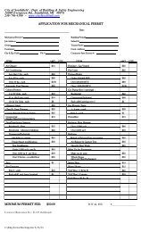
2. Soil Erosion and Sedimentation Control Permit:<br />
This permit is required prior to final construction plan approval.<br />
Applications are available at the <strong>City</strong> <strong>Engineering</strong> Division <strong>of</strong>fices. A<br />
bond may be required in accordance with <strong>City</strong> Code, Chapter 49,<br />
Article XI.<br />
3. Michigan Department <strong>of</strong> Environmental Quality Water Main:<br />
All water main requires a water supply permit from the Michigan<br />
Department <strong>of</strong> Environmental Quality (MDEQ). Submit an Act 399<br />
permit application [http://www.michigan.gov/deq/0,1607,7-135-<br />
3313_3675_3691-72232--,00.html] to the <strong>Engineering</strong> Division upon<br />
request. The <strong>City</strong> <strong>of</strong> <strong>Southfield</strong>’s WSSN number is 06160. The <strong>City</strong><br />
will directly request approval from the MDEQ during the course <strong>of</strong><br />
engineering plan approval.<br />
4. Michigan Department <strong>of</strong> Environmental Quality Sanitary Sewer:<br />
All sanitary sewers require a permit from the Michigan Department <strong>of</strong><br />
Environmental Quality (MDEQ). Submit a Part 41 permit application<br />
[http://www.michigan.gov/deq/0,1607,7-135-3313_44117---,00.html] to the<br />
<strong>Engineering</strong> Division upon request. The <strong>City</strong> will submit the request<br />
for approval from the MDEQ during the course <strong>of</strong> engineering plan<br />
approval.<br />
5. Oakland County Drain Commission:<br />
All taps to sanitary sewers require permits from the Oakland County<br />
Drain Commission (OCDC.)<br />
/Forms/Site Plan <strong>Design</strong> <strong>Standards</strong> 10-01-07 Revision)<br />
Page 12 <strong>of</strong> 28
6. Road Commission for Oakland County:<br />
All work in roads under the jurisdiction <strong>of</strong> the Road Commission for<br />
Oakland County (RCOC) requires a permit from the Road Commission<br />
for Oakland County.<br />
7. Other Permits:<br />
A. GENERAL:<br />
Other agencies that may require a permit will be designated on the<br />
approved plan. These permits are generally the contractor’s<br />
responsibility and will generally be required prior to construction.<br />
<strong>City</strong> <strong>of</strong> <strong>Southfield</strong>;<br />
Michigan Department <strong>of</strong> Transportation;<br />
Michigan Department <strong>of</strong> Environmental Quality;<br />
Oakland County Drain Commission.<br />
II. SURVEY<br />
1. A complete topographical survey is required for all sites. Existing <strong>of</strong>fsite<br />
elevations must be given at a minimum <strong>of</strong> fifty (50’) feet and onehundred<br />
(100’) feet abutting the entire perimeter <strong>of</strong> the site. Grades<br />
shall be indicated at all property corners and along all property lines.<br />
On-site, intermittent elevations or defined contours are required to<br />
establish the existing site drainage.<br />
2. All existing conditions shall be indicated. Locations and elevations<br />
must be given on the following:<br />
- Existing drainage courses;<br />
- Upstream and downstream culverts;<br />
- All utilities, including sanitary, water main, gas,<br />
telephone, electrical, etc. Inverts and castings and<br />
finish grades are required where applicable;<br />
- Sidewalks;<br />
- Finished grades <strong>of</strong> all adjacent buildings;<br />
- All easements.<br />
3. A USGS Benchmark (B.M.) is required and a site B.M. for construction<br />
purposes must be identified on the plan.<br />
/Forms/Site Plan <strong>Design</strong> <strong>Standards</strong> 10-01-07 Revision)<br />
Page 13 <strong>of</strong> 28
4. Road topography shall extend across the entire site with grades shown<br />
on both sides <strong>of</strong> the street for:<br />
- Property line;<br />
- Ditch center line;<br />
- Top <strong>of</strong> bank;<br />
- Edge <strong>of</strong> shoulder;<br />
- Edge <strong>of</strong> pavement or top <strong>of</strong> curb;<br />
- Street crown or center line.<br />
5. Property lines must be indicated by distances and bearings where<br />
applicable and property corners must be identified as either found or<br />
set.<br />
6. Existing rights-<strong>of</strong>-way <strong>of</strong> adjacent roads must be indicated.<br />
III. SOIL EROSION AND SEDIMENTATION CONTROL<br />
A. SITES REQUIRING PERMITS:<br />
All sites having a construction area <strong>of</strong> one or more acres require a Soil Erosion<br />
Permit. All sites within five hundred (500’) feet <strong>of</strong> a drainage course require a<br />
Soil Erosion Permit.<br />
B. INTENT OF PERMIT:<br />
The intent <strong>of</strong> this requirement is to ensure that no silt or sediment enters the<br />
public streams or water courses. This is accomplished through means <strong>of</strong><br />
siltation basins, filters, diversions, etc.<br />
C. PLAN REQUIRED:<br />
A separate soil erosion and sedimentation control plan is required for all sites<br />
that require a permit. Itemized on this plan shall be step-by-step requirements<br />
for controlling siltation. No work (including site clearing) will be allowed until<br />
approved siltation control measures are in effect.<br />
Accelerated erosion and sedimentation must be prevented during all<br />
phases <strong>of</strong> construction, including:<br />
D. INSPECTION:<br />
- Initial site clearing;<br />
- Utility construction;<br />
- Building construction;<br />
- Site paving;<br />
- Final site approval.<br />
/Forms/Site Plan <strong>Design</strong> <strong>Standards</strong> 10-01-07 Revision)<br />
Page 14 <strong>of</strong> 28
Inspections will be made periodically throughout construction on the<br />
maintenance and effectiveness <strong>of</strong> soil sedimentation control methods.<br />
The costs <strong>of</strong> these inspections are charged against the inspection escrow<br />
account. If inspection reveals that the controls are not being implemented, a<br />
Stop Work Order on all site construction may be issued.<br />
A. NOTES:<br />
NOTE: THE SILTATION CONTROL REQUIREMENTS MAY CONTROL<br />
THE PROGRESS AND SCHEDULING OF ALL CONSTRUCTION<br />
ON THE SITE.<br />
IV. WATER MAIN<br />
1. When applicable, the <strong>City</strong> <strong>of</strong> <strong>Southfield</strong> detail sheets must be included<br />
with the plans.<br />
2. A quantity list itemizing all proposed public water main construction<br />
must appear on the plan.<br />
B. SIZES AND DISTRIBUTION:<br />
1. The minimum size water main in the <strong>City</strong> <strong>of</strong> <strong>Southfield</strong> shall be eight<br />
inches. Six-inch mains may be used only for single fire hydrant leads<br />
having a maximum length <strong>of</strong> forty (40) feet. No service leads are<br />
allowed from a six (6”) inch main. Maximum dead end mains are as<br />
follows:<br />
- 400 ft. for eight (8”) inch Mains;<br />
- 1,000 ft. for twelve (12”) inch Mains.<br />
Reducers are not allowed to meet the dead end requirements.<br />
2. Twelve-inch water main may be considered as minimum for internal<br />
transmission on industrial and multiple sites.<br />
3. Looping <strong>of</strong> mains will be required, wherever possible. All mains must<br />
end with a hydrant or blow-<strong>of</strong>f.<br />
4. The extension <strong>of</strong> water main will generally be required across the entire<br />
frontage <strong>of</strong> the site.<br />
5. All water main installations must be in accordance with the <strong>City</strong>’s<br />
water Master Plan.<br />
/Forms/Site Plan <strong>Design</strong> <strong>Standards</strong> 10-01-07 Revision)<br />
Page 15 <strong>of</strong> 28
C. VALVES:<br />
Gate valve spacing will generally be regulated by providing the following<br />
provisions.<br />
In the event <strong>of</strong> a breakage:<br />
- No more than thirty (30) single or multiple family units will<br />
lose service;<br />
- No more than one hydrant will be out <strong>of</strong> service;<br />
- No more than four valves shall have to be closed to isolate the<br />
break, and where possible, three valves should isolate the break;<br />
- On-line valve spacing shall be a maximum <strong>of</strong> one thousand<br />
(1,000’) feet.<br />
D. AUTOMATIC FIRE SPRINKLER SERVICE CONNECTIONS:<br />
The <strong>City</strong> will allow installation <strong>of</strong> an un-metered fire service connection<br />
provided adequate provision is made to prevent the use <strong>of</strong> water from such fire<br />
service for purposes other than fire extinguishing. In no case should hydrants be<br />
placed downstream <strong>of</strong> any check valve used for automatic sprinkler protection.<br />
Where hydrants are necessary, separate mains shall be installed for fire sprinkler<br />
service and hydrant protection. Sprinkler systems are not a substitute for<br />
standard requirements for hydrants and the fire suppression system supply line<br />
shall have its own isolation valve so that the water supply to the structure can be<br />
turned <strong>of</strong>f while still keeping the fire suppression system in service.<br />
E. HYDRANTS:<br />
1. Single family residential spacing shall be a maximum <strong>of</strong> six<br />
hundred (600’) feet.<br />
2. Commercial, industrial and multiple spacing shall generally be a<br />
maximum <strong>of</strong> five hundred (500’) feet on line, but may vary to meet the<br />
following requirements:<br />
All points on the exterior <strong>of</strong> a building shall be no closer<br />
than fifty (50’) feet, nor further than two hundred-and-fifty<br />
(250’) feet from a hydrant. Distances shall be measured<br />
along the shortest feasible exterior route (never through<br />
buildings) for laying hose.<br />
3. Any hydrant located in a parking lot shall be protected by a minimum <strong>of</strong><br />
six (6”) inch curb or standard hydrant guard posts. In all cases, the<br />
visibility <strong>of</strong> the hydrant must be considered. No parking will be allowed<br />
within ten feet <strong>of</strong> the hydrant.<br />
/Forms/Site Plan <strong>Design</strong> <strong>Standards</strong> 10-01-07 Revision)<br />
Page 16 <strong>of</strong> 28
4. A hydrant is required to be located within one hundred (100’) feet from<br />
the fire department connection on a building. Additional hydrants may be<br />
required depending on the specific use.<br />
F. MATERIALS:<br />
All materials shall be in conformance with the <strong>City</strong> <strong>of</strong> <strong>Southfield</strong> current<br />
standards and specifications.<br />
G. CONSTRUCTION:<br />
No building permits for wood frame construction will be issued above the<br />
foundation for any development prior to the active service <strong>of</strong> the required mains<br />
and hydrants and adequate access for fire fighting equipment. No occupancy<br />
shall be allowed in any instance without the required mains, hydrants and<br />
sprinklers being <strong>of</strong>ficially dedicated to the <strong>City</strong> <strong>of</strong> <strong>Southfield</strong>.<br />
H. EASEMENTS:<br />
All public water mains must be located in an easement or public right-<strong>of</strong>-way.<br />
Standard easement forms are available at the <strong>City</strong> <strong>Engineering</strong> Division. The<br />
minimum easement shall be twelve (12’) feet. The dedication <strong>of</strong> the easement<br />
will be required prior to use <strong>of</strong> the system.<br />
A. GENERAL:<br />
V. SANITARY SEWER<br />
1. Public sanitary sewers are required when two or more connections are<br />
made to the same sewer. In most instances, including multiple unit<br />
developments, the sewers may have to be public, even though the<br />
project has one owner.<br />
2. The extension <strong>of</strong> the sanitary sewers will generally be required across<br />
the entire frontage <strong>of</strong> the site, and to provide for upstream discharge.<br />
3. All construction shall conform to the current OCDC sanitary sewer<br />
standards and specifications.<br />
/Forms/Site Plan <strong>Design</strong> <strong>Standards</strong> 10-01-07 Revision)<br />
Page 17 <strong>of</strong> 28
B. NOTES:<br />
1. Where required, OCDC sanitary sewer detail sheets shall be included<br />
with plans.<br />
2. A quantity summary, itemizing all proposed public sanitary sewer<br />
construction, must appear on the plans.<br />
C. SEWERAGE:<br />
Downspouts, weep tile, footing drains, or any conduit that carries storm or ground<br />
water shall not be allowed to discharge into the sanitary system.<br />
D. GRADE:<br />
1. The following table represents the minimum and maximum grade for public<br />
sanitary sewers. Maximum velocity may not exceed ten (10’) feet per<br />
second.<br />
Size Standard Grade Minimum<br />
Grade<br />
10” 0.60% 0.30%<br />
12” 0.40% 0.22%<br />
15” 0.24% 0.15%<br />
18” 0.18% 0.12%<br />
21” 0.14% 0.10%<br />
2. All upstream dead-end sewers shall have a minimum last run grade <strong>of</strong> one<br />
(1.0%) percent.<br />
/Forms/Site Plan <strong>Design</strong> <strong>Standards</strong> 10-01-07 Revision)<br />
Page 18 <strong>of</strong> 28
E. MANHOLES:<br />
1. Sanitary Sewer Manholes shall be spaced as follows:<br />
/Forms/Site Plan <strong>Design</strong> <strong>Standards</strong> 10-01-07 Revision)<br />
Page 19 <strong>of</strong> 28<br />
Size Standard Run Maximum Sewer<br />
Run<br />
10” 300 Ft. 330 Ft.<br />
12” 400 Ft. 450 Ft.<br />
15” 500 Ft. 500 Ft.<br />
18” 600 Ft. 600 Ft.<br />
21” 600 Ft. 600 Ft.<br />
2. A manhole will be required at all changes in alignment, size or grade.<br />
F. LOCATION:<br />
1. Sanitary sewers shall be located so as to provide unrestricted access for<br />
maintenance and inspection. A minimum alignment separation <strong>of</strong> ten<br />
(10’) feet must be maintained between the sewer and all water mains. The<br />
water main and sanitary sewer shall be located on opposite sides <strong>of</strong> the<br />
street, wherever possible.<br />
2. All public sewers must be located in a public right-<strong>of</strong>-way or an easement.<br />
Standard Easement forms are available at the <strong>City</strong> <strong>Engineering</strong> Division.<br />
The easement size will vary individually as required for maintenance and<br />
access. The minimum sanitary sewer easement shall be twenty (20’) feet.<br />
The dedication <strong>of</strong> the easement will be required prior to use <strong>of</strong> the system.<br />
G. LEADS:<br />
1. Service leads shall be a minimum <strong>of</strong> six (6”) inches in diameter with a<br />
minimum slope <strong>of</strong> one (1.0%) percent.<br />
2. Private sanitary sewer leads <strong>of</strong> excessive length, although not a public<br />
sewer, may require inspection and testing. Each site will be considered<br />
individually by the <strong>Engineering</strong> Division.<br />
3. Service leads shall not be made into a manhole without written permission<br />
from the <strong>City</strong> Engineer.<br />
4. The maximum depth <strong>of</strong> a sewer lead is ten (10’) feet at the property line.
H. PROFILE:<br />
The following information shall be indicated on the sanitary sewer pr<strong>of</strong>ile:<br />
- Length <strong>of</strong> run between manholes;<br />
- Type and class <strong>of</strong> pipe between manholes;<br />
- Size and grade <strong>of</strong> pipe between manholes;<br />
- Top <strong>of</strong> casting and invert <strong>of</strong> all manholes;<br />
- Existing and proposed ground elevation along the run <strong>of</strong> sewer;<br />
- Progressive numbering system;<br />
- All utility crossings;<br />
- Special backfill areas;<br />
- Provisions for infiltration testing.<br />
I. DROP CONNECTIONS:<br />
External drop connections are required where the invert <strong>of</strong> the outlet pipe is<br />
eighteen (18”) inches or more below the invert <strong>of</strong> the inlet pipe. Internal drop<br />
connections will generally not be allowed.<br />
J. SEPTIC TANK:<br />
If sanitary sewer is not available, a copy <strong>of</strong> a valid septic system permit from the<br />
Oakland County Health Division must be submitted prior to approval.<br />
A. GENERAL:<br />
/Forms/Site Plan <strong>Design</strong> <strong>Standards</strong> 10-01-07 Revision)<br />
Page 20 <strong>of</strong> 28<br />
VI. STORM SEWER<br />
1. All storm sewers must conform to the project’s grading plan.<br />
2. All construction must conform to <strong>Southfield</strong>’s <strong>City</strong> Code and OCDC<br />
standards.<br />
3. Where required, the OCDC storm drain detail sheets shall be included<br />
with plans.<br />
4. Underground drainage facilities will generally be required. All run-<strong>of</strong>f onsite<br />
must be accommodated and discharged in a controlled manner. The<br />
minimum on site pipe size is eight (8”) inches. All public systems shall<br />
have a minimum pipe size <strong>of</strong> twelve (12”) inches. A minimum pipe size<br />
<strong>of</strong> twelve (12”) inches shall also be required for all storm sewer from the<br />
tap to the public system to the first structure upstream.<br />
5. Sump pump discharge must be directed into the storm sewer via an<br />
enclosed system. A minimum <strong>of</strong> four (4”) inch pipe shall be utilized and<br />
will also be allowed to discharge unrestricted.
B. STRUCTURE:<br />
1. Catch basins at the upstream end <strong>of</strong> the system shall be a minimum <strong>of</strong><br />
twenty-four (24”) inches in diameter. Catch basins with an inlet pipe shall<br />
have a minimum diameter <strong>of</strong> thirty-six (36”) inches. All manholes and<br />
public catch basins shall be a minimum <strong>of</strong> forty-eight (48”) inches in<br />
diameter.<br />
2. The first structure upstream from a public system within the confines <strong>of</strong><br />
the private development shall be forty-eight (48”) inches in diameter and<br />
have a twenty-four (24”) inch sump.<br />
3. Manholes shall be located at:<br />
C. STORM SEWER DESIGN:<br />
a) All changes in alignment;<br />
b) Points where the sewer changes size;<br />
c) Points where the grade changes;<br />
d) Junction <strong>of</strong> sewer lines.<br />
1. Storm sewers shall be designed using the Manning Equation for pipes<br />
flowing full. Run<strong>of</strong>f shall be determined using the Rational Method with<br />
an intensity formula <strong>of</strong> I = 175/T+25. The initial time <strong>of</strong> concentration<br />
shall generally be twenty (20) minutes and<br />
T+25 minutes<br />
maximum.<br />
2. Storm sewer design computations must be submitted for review by the<br />
<strong>City</strong> Engineer. The velocity shall be a minimum <strong>of</strong> two and one-half (2.5)<br />
fps and shall not exceed ten (10) fps.<br />
3. The hydraulic gradient must be maintained within the pipe, wherever<br />
possible.<br />
4. Run<strong>of</strong>f coefficients shall be determined for each individual drainage area<br />
and calculations for each drainage area must be submitted as part <strong>of</strong> the<br />
design computations.<br />
5. A storm drainage district map must be provided showing all drainage<br />
districts within the development. The district limits must be overlaid on a<br />
proposed grading plan for the site. Color coding is encouraged.<br />
6. All upstream drainage must be accommodated on-site. Allowances for<br />
upstream area must be based on ultimate improvements and run<strong>of</strong>f.<br />
Discharge must not be diverted onto abutting properties.<br />
/Forms/Site Plan <strong>Design</strong> <strong>Standards</strong> 10-01-07 Revision)<br />
Page 21 <strong>of</strong> 28
7. The outlet must be in accordance with the project’s grading plan and the<br />
existing natural drainage courses in the area.<br />
D. PLAN AND PROFILE:<br />
E. TAPS:<br />
1. All public storm sewers must be shown in pr<strong>of</strong>ile. For develop-ments<br />
larger than one acre, the private sewer must also be shown in pr<strong>of</strong>ile.<br />
2. The following must be shown in pr<strong>of</strong>ile:<br />
- Length <strong>of</strong> run between manholes and catch basins;<br />
- Type and class <strong>of</strong> pipe between manholes and catch basins;<br />
- Size and grade <strong>of</strong> sewer between manholes;<br />
- Top <strong>of</strong> casting elevations;<br />
- Inverts <strong>of</strong> all pipes at manholes;<br />
- Proposed and existing ground elevations along the run <strong>of</strong> sewer;<br />
- Progressive numbering system on all manholes and catch basins;<br />
- All utility crossings;<br />
- Special backfill areas;<br />
- Type <strong>of</strong> joint.<br />
Connections must be made at manholes. Blind taps are generally not allowed.<br />
F. DETENTION:<br />
1. All sites within the <strong>City</strong> <strong>of</strong> <strong>Southfield</strong> shall be required to provide<br />
detention <strong>of</strong> storm water run<strong>of</strong>f for the one hundred (100) year design<br />
storm, treating and storing for the first flush and bank-full flood. <strong>Design</strong><br />
shall be per the current Oakland County Drain Commission <strong>Engineering</strong><br />
<strong>Design</strong> <strong>Standards</strong> for storm water facilities.<br />
2. All open detention basins must be fenced if the side slopes exceed one (1)<br />
vertical to six (6) horizontal. This may be waived by the <strong>Engineering</strong><br />
Division when the design is an integral part <strong>of</strong> the landscaping and the<br />
location and depth does not present a potential hazard. The earthen side<br />
slope shall be one (1) vertical to three (3) minimum horizontal. Fences<br />
shall be a minimum <strong>of</strong> six (6’) feet high chain link with a locking access<br />
gate, eight (8’) feet wide.<br />
3. Minimum grade on the bottom <strong>of</strong> the detention basin shall be one and twotenths<br />
(1.2%) percent when sodded.<br />
4. All detention systems are required to be maintained as part <strong>of</strong> the site<br />
Maintenance Agreement on file with the approved Site Plan.<br />
G. PUBLIC STORM SEWER:<br />
/Forms/Site Plan <strong>Design</strong> <strong>Standards</strong> 10-01-07 Revision)<br />
Page 22 <strong>of</strong> 28
1. All public storm sewers must be located in a public right-<strong>of</strong>-way or an<br />
easement. Standard easement forms are available at the <strong>Engineering</strong><br />
Division. The easement size will vary as required for maintenance and<br />
access. The minimum storm sewer easement shall be twenty (20’) feet.<br />
The dedication <strong>of</strong> the easement will be required prior to use <strong>of</strong> the system.<br />
2. Any storm sewer that accepts run<strong>of</strong>f from abutting property or public<br />
right-<strong>of</strong>-way must be placed in a minimum twenty (20’) foot storm sewer<br />
easement.<br />
3. All public storm sewer shall be a minimum <strong>of</strong> twelve (12”) inch diameter<br />
Cl.IV concrete pipe with premium gasketed joints.<br />
A. GENERAL:<br />
VII. PAVING AND GRADING<br />
1. All public paving shall conform to the current standards and specifications<br />
<strong>of</strong> the <strong>City</strong> <strong>of</strong> <strong>Southfield</strong>.<br />
2. Where required, the <strong>City</strong> <strong>of</strong> <strong>Southfield</strong> pavement details shall appear on<br />
the plans.<br />
B. ON SITE:<br />
1. A cross section <strong>of</strong> all on-site paving is required on the plans.<br />
Minimum requirements are as follows:<br />
a) Commercial and Multiple:<br />
Three (3”) inch asphalt on six (6”) inch gravel base;<br />
Six (6”) inch concrete.<br />
b) Industrial:<br />
Four (4”) inch asphalt on eight (8”) inch gravel base;<br />
Eight (8”) inch concrete.<br />
These minimum requirements are based on adequate sub-grade, sub-grade<br />
drainage and average live loads. Each site will be examined individually<br />
and additional pavement thickness and/or increased base requirements<br />
may be necessary.<br />
/Forms/Site Plan <strong>Design</strong> <strong>Standards</strong> 10-01-07 Revision)<br />
Page 23 <strong>of</strong> 28
2. Minimum surface grade for asphalt paving shall be one (1.0%) percent.<br />
Minimum surface grade for concrete paving shall be six-tenths (0.6%) <strong>of</strong><br />
an inch.<br />
C. CITY PUBLIC RIGHT-OF-WAY:<br />
1. A cross section <strong>of</strong> all <strong>of</strong>f-site paving is required. Minimum requirements<br />
are dependent on the type <strong>of</strong> existing pavement as follows:<br />
- Concrete major thoroughfare and collector roads require nine (9”) inches<br />
<strong>of</strong> PC concrete on sand sub-base;<br />
- Asphalt major thoroughfare and collector roads require eight (8”) inches<br />
<strong>of</strong> asphalt;<br />
- Concrete local roads generally require seven (7”) inches <strong>of</strong> PC concrete<br />
sand sub-base;<br />
- Asphalt local roads generally require three (3”) inches <strong>of</strong> asphalt on an<br />
eight (8”) inch gravel base;<br />
- Requirements for existing gravel roads will be considered on an<br />
individual basis by the <strong>City</strong> <strong>Engineering</strong> Division.<br />
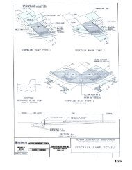
2. Six (6”) inch concrete curb and gutter is required on all approaches.<br />
3. Passing lanes, acceleration lanes and tapers, and deceleration lanes and<br />
tapers will be required in accordance with the current Road Commission<br />
for Oakland County specifications and guidelines. If curb is required on<br />
the passing acceleration, or deceleration lanes, it shall be six (6”) inch<br />
concrete curb and gutter.<br />
/Forms/Site Plan <strong>Design</strong> <strong>Standards</strong> 10-01-07 Revision)<br />
Page 24 <strong>of</strong> 28
4. The dedication <strong>of</strong> the following right-<strong>of</strong>-way along the frontage <strong>of</strong> the site<br />
to the ultimate requirement for future improvement is requested:<br />
/Forms/Site Plan <strong>Design</strong> <strong>Standards</strong> 10-01-07 Revision)<br />
Page 25 <strong>of</strong> 28<br />
- 120 feet - major thoroughfare;<br />
- 86 feet - collector road;<br />
- 60 feet - local road.<br />
5. All shoulders shall be eight (8”) inches <strong>of</strong> 22A gravel, eight (8’) feet wide<br />
on thoroughfares and four (4’) feet wide on local roads.<br />
6. Sufficient proposed grades must be given to determine proposed grading<br />
<strong>of</strong> all right-<strong>of</strong>-way improvements.<br />
D. DRAINAGE IN RIGHT-OF-WAY:<br />
1. Enclosures <strong>of</strong> drainage ditches across the frontage <strong>of</strong> the site will<br />
generally not be permitted. The <strong>City</strong> <strong>Engineering</strong> Division may, however,<br />
require the enclosure if adequate controls on pavements and shoulders<br />
cannot be maintained and the health, safety and welfare <strong>of</strong> the general<br />
public is endangered.<br />
2. Side slopes on open ditch drainage shall be three (3) minimum horizontal<br />
to one (1) vertical. The ditch bottom shall be two (2’) feet wide.<br />
E. SIDEWALKS AND NON-MOTORIZED PATH:<br />
1. Sidewalks are required along all rights-<strong>of</strong>-way. They shall be located in<br />
the right-<strong>of</strong>-way, one foot from the ultimate right-<strong>of</strong>-way line.<br />
2. The walk shall be five (5’) feet wide, constructed <strong>of</strong> four (4”) inches <strong>of</strong> PC<br />
concrete on compacted porous sub-grade. The walk must be continued<br />
through driveway sections where it shall be increased in thickness to six<br />
(6”) inches on major thoroughfares and collector roads and six (6”) inches<br />
at corners and through driveways. Curbs must be tapered to meet the<br />
walk. Cross slopes on the sidewalk shall be one-quarter (1/4”) inch per<br />
foot toward the street. Non-motorized paths must be eight (8’) feet wide,<br />
constructed <strong>of</strong> two (2”) inch bituminous surface on a minimum <strong>of</strong> four<br />
(4”) inches <strong>of</strong> compacted porous base.<br />
3. Proposed grades must be indicated along the property line and on the<br />
walk, driveways, and intermittent locations along the length <strong>of</strong> the walk, at<br />
no less than intervals <strong>of</strong> fifty (50’) feet.<br />
4. Any structures, hydrants, poles, etc. that are existing along the alignment<br />
<strong>of</strong> the walk, must be adjusted or relocated at the expense and coordination<br />
<strong>of</strong> the developer. All sidewalk construction shall be in accordance with<br />
the Americans with Disabilities Act (ADA) <strong>of</strong> 1990.
5. All sidewalk ramps are required to have Detectable Warning Strips.<br />
Detectable Warnings shall be cast-in-place or adhesive. Imprinting <strong>of</strong><br />
concrete will not be permitted.<br />
F. SITE GRADING:<br />
1. Sufficient proposed grades must be indicated on the plan to ensure that:<br />
- Drainage is adequately discharged <strong>of</strong>f-site with proper retention;<br />
- No upstream drainage is restricted;<br />
- Paving is in accordance with standards outlined herein;<br />
- The site, in general, drains without standing water.<br />
2. Elevations representing the brick ledge, finished grade, and the first floor<br />
grade must be indicated.<br />
3. Proposed grading shall meet abutting property line elevations.<br />
Differentials in grade must incorporate a minimum four (4) horizontal to<br />
one (1) vertical slope to the abutting property line.<br />
4. Retaining walls are discouraged. Any wall separating a differential grade<br />
<strong>of</strong> more than twelve (12”) inches shall be considered a retaining structure<br />
and will require a structural engineering design and review.<br />
5. The finish grade adjacent to the structure must be a minimum <strong>of</strong> eighteen<br />
(18”) inches above the side yard swale elevation.<br />
/Forms/Site Plan <strong>Design</strong> <strong>Standards</strong> 10-01-07 Revision)<br />
Page 26 <strong>of</strong> 28
IX. REQUIREMENTS FOR CITY ACCEPTANCE OF UTILITIES<br />
GENERAL<br />
The <strong>City</strong> <strong>of</strong> <strong>Southfield</strong> shall take over water supply, sewage disposal systems and streets<br />
existing in developments which have been constructed under a Michigan Department <strong>of</strong><br />
Health permit issued to the <strong>City</strong> <strong>of</strong> <strong>Southfield</strong>. Before taking over the above mentioned<br />
infrastructure, and before Building Permits are issued, or taps are made to the system, the<br />
following must be submitted to the Department <strong>of</strong> Public Works:<br />
1. A Quit Claim Deed or Bill-<strong>of</strong>-Sale from the developer for the<br />
materials used in these improvements.<br />
2. A letter from the engineer who designed the improvements stating the<br />
final construction cost <strong>of</strong> these improvements and also indicating that<br />
this construction has been completed in accordance with the approved<br />
plans.<br />
3. Two (2) sets <strong>of</strong> As-Built drawings on bond paper, one (1) set on mylar.<br />
4. Sworn statement from the contractor indicating that all labor and<br />
materials have been paid in full.<br />
5. Maintenance and Guarantee Bond in favor <strong>of</strong> the <strong>City</strong> <strong>of</strong> <strong>Southfield</strong> in<br />
the amount <strong>of</strong> 100% <strong>of</strong> the final construction cost <strong>of</strong> the improvement.<br />
This bond is to be on the <strong>City</strong>’s form and shall run for two (2) years<br />
from the date <strong>of</strong> acceptance by the <strong>City</strong> Council.<br />
Dedicate to the <strong>City</strong> all necessary easements and rights-<strong>of</strong>-way.<br />
/Forms/Site Plan <strong>Design</strong> <strong>Standards</strong> 10-01-07 Revision)<br />
Page 27 <strong>of</strong> 28
CITY OF SOUTHFIELD STANDARD NOTES<br />
1. Notify the <strong>City</strong> <strong>of</strong> <strong>Southfield</strong> <strong>Engineering</strong> Division (248) 796-4831<br />
a minimum <strong>of</strong> forty-eight (48) hours prior to the start <strong>of</strong> construction.<br />
2. All construction must conform to the current standards and specifications<br />
adopted by the <strong>City</strong> <strong>of</strong> <strong>Southfield</strong>.<br />
3. Utilities must be located underground.<br />
4. Call MISS DIG (1-800-647-7344 / 1-800-MISS DIG) a minimum <strong>of</strong><br />
seventy-two (72) hours prior to the start <strong>of</strong> construction.<br />
5. All soil erosion and silt must be controlled and contained on-site.<br />
6. All excavation under or within three (3’) feet <strong>of</strong> public pavement, existing<br />
or proposed, shall be backfilled and compacted with sand (Class II<br />
MDOT).<br />
7. The contractor is responsible for all damage to existing utilities.<br />
8. Prior to the issuance <strong>of</strong> an occupancy permit, engineering site inspection is<br />
required.<br />
/Forms/Site Plan <strong>Design</strong> <strong>Standards</strong> 10-01-07 Revision)<br />
Page 28 <strong>of</strong> 28