Experiment 2 Soldering Parallel and Series Circuits and using the ...
Experiment 2 Soldering Parallel and Series Circuits and using the ...
Experiment 2 Soldering Parallel and Series Circuits and using the ...

You also want an ePaper? Increase the reach of your titles
YUMPU automatically turns print PDFs into web optimized ePapers that Google loves.
<strong>Experiment</strong> 2 <strong>Soldering</strong> <strong>Parallel</strong> <strong>and</strong> <strong>Series</strong><br />
<strong>Circuits</strong> <strong>and</strong> <strong>using</strong> <strong>the</strong> Digital<br />
Multimeter<br />
Introduction<br />
<strong>Soldering</strong> is <strong>the</strong> most common means of joining components to each o<strong>the</strong>r or to circuit<br />
boards in electronics. Although it is one of <strong>the</strong> most reliable methods for making such<br />
connections, this reliability can be significantly reduced by poor soldering techniques,<br />
resulting in low quality soldered joints. During soldering, two or more metal parts are<br />
united by an alloy. The alloy melts at a lower temperature than ei<strong>the</strong>r of <strong>the</strong> metals.<br />
The liquefied solder permeates into <strong>the</strong> molecular structure of each of <strong>the</strong> metals,<br />
forming a common bond on cooling, that unites <strong>the</strong> metals. The melting point for<br />
solder depends on <strong>the</strong> composition of <strong>the</strong> alloy used.<br />
The DMM is a basic test instrument. It can measure resistance, voltage, current <strong>and</strong><br />
capacitance; it may also contain a diode tester <strong>and</strong> a transistor tester. It can measure<br />
both DC <strong>and</strong> AC quantities.<br />
Objectives<br />
The objective of this laboratory exercise is to practice:<br />
1. Reading resistor colour codes;<br />
2. <strong>Soldering</strong> simple circuits onto stripboards;<br />
3. Using a DMM by taking measurements of many of <strong>the</strong> quantities which it is<br />
commonly used for.<br />
Component <strong>and</strong> Equipment Requirements<br />
• Resistors: 120 Ω, 150 Ω, 180 Ω, 56 Ω, 3.3 k Ω, 820 Ω, 2.7 k Ω, 1 k Ω <strong>and</strong><br />
390 Ω<br />
• Red <strong>and</strong> black str<strong>and</strong>ed wire<br />
• Red <strong>and</strong> black single core wire<br />
• Solder<br />
• Stripboard<br />
• Solder tip cleaner<br />
• Digital Multimeter<br />
• Oscilloscope <strong>and</strong> scope leads<br />
• Low voltage DC power supply<br />
• Low voltage AC power supply<br />
• <strong>Soldering</strong> iron st<strong>and</strong><br />
Some simple rules<br />
• Always keep <strong>the</strong> tip of your soldering iron clean by wiping it frequently on a<br />
damp sponge.<br />
7
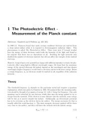
PY2108 <strong>Experiment</strong>al Methods I<br />
_____________________________________________________________________<br />
• Work in a well-ventilated area.<br />
• When you burn yourself, quickly run cold tap water over <strong>the</strong> burn to limit<br />
damage to your skin.<br />
• For safety, always park a hot soldering iron in a bench st<strong>and</strong>.<br />
• Always turn off <strong>the</strong> soldering iron when it is not in use.<br />
• After soldering, examine <strong>the</strong> join carefully. If <strong>the</strong> solder is dull grey in colour,<br />
you should reheat <strong>the</strong> joint <strong>and</strong> apply some more solder. The solder should<br />
have a bright, silver colour in <strong>the</strong> joint.<br />
Part 1: <strong>Soldering</strong> parallel <strong>and</strong> series circuits<br />
1. Use <strong>the</strong> digital multimeter (DMM) to measure <strong>the</strong> resistance of two resistors<br />
(R1 <strong>and</strong> R2) of nominal values 1 kΩ <strong>and</strong> 390 Ω. Use Figure 2.1 to select <strong>the</strong><br />
resistors.<br />
2. Mount <strong>the</strong> resistors onto <strong>the</strong> stripboard as shown in Figure 2.2. Bend <strong>the</strong><br />
resistor leads as necessary <strong>and</strong> insert <strong>the</strong>m through suitable holes on <strong>the</strong> board.<br />
To hold <strong>the</strong> resistor in place while you are soldering, you may find that it is<br />
useful to bend <strong>the</strong> leads at <strong>the</strong> bottom of <strong>the</strong> board at an angle. Once you are<br />
sure that <strong>the</strong> component is properly placed, you can more on to <strong>the</strong> next step.<br />
Figure 2.1: Resistor colour codes.<br />
8
PY2108 <strong>Experiment</strong>al Methods I<br />
_____________________________________________________________________<br />
Figure 2.2: Schematic of <strong>the</strong> two resistors in series circuit.<br />
3. Apply a very small amount of solder to <strong>the</strong> tip of<br />
<strong>the</strong> soldering iron (Figure 2.3). This will help to<br />
conduct <strong>the</strong> heat to <strong>the</strong> component <strong>and</strong> board, but<br />
is not <strong>the</strong> solder that will make up <strong>the</strong> joint. You<br />
are now ready to heat <strong>the</strong> resistor <strong>and</strong> board. Lay<br />
<strong>the</strong> iron tip so that it rests against both <strong>the</strong> resistor<br />
lead <strong>and</strong> <strong>the</strong> board. It may take one or two<br />
seconds to heat <strong>the</strong> component up enough to<br />
solder.<br />
4. Once <strong>the</strong> component lead <strong>and</strong> solder pad has<br />
heated up, you are ready to apply solder. Touch<br />
<strong>the</strong> tip of <strong>the</strong> str<strong>and</strong> of solder to <strong>the</strong> component<br />
lead <strong>and</strong> pad, but not <strong>the</strong> tip of <strong>the</strong> iron (Figure<br />
2.4). The solder should flow freely around <strong>the</strong><br />
lead <strong>and</strong> pad. Once <strong>the</strong> pad is coated, you can stop<br />
adding solder <strong>and</strong> remove <strong>the</strong> soldering iron (in<br />
that order). Don't move <strong>the</strong> joint for a few<br />
seconds to allow <strong>the</strong> solder to cool, o<strong>the</strong>rwise<br />
you will end up with a weak, cold joint.<br />
Figure 2.3: Placing <strong>the</strong><br />
resistors on <strong>the</strong> stripboard.<br />
Figure 2.4: Applying solder<br />
to <strong>the</strong> joint.<br />
5. Repeat <strong>the</strong> above steps so that <strong>the</strong> two resistors are soldered in place.<br />
6. Solder two flying leads onto <strong>the</strong> board as shown in Figure 2.2. You now have<br />
a simple circuit of two resistors in series.<br />
7. Use <strong>the</strong> DMM to measure <strong>the</strong> total circuit resistance (between points A <strong>and</strong> C).<br />
How does your measured value compared with your calculated value, allowing<br />
for <strong>the</strong> tolerances of <strong>the</strong> resistors<br />
8. Calculate <strong>the</strong> maximum voltage which can be applied to this circuit without<br />
overheating ei<strong>the</strong>r of <strong>the</strong> resistors. Assume <strong>the</strong> power dissipation of <strong>the</strong><br />
resistors is 0.5 W.<br />
9
PY2108 <strong>Experiment</strong>al Methods I<br />
_____________________________________________________________________<br />
9. Set <strong>the</strong> output of <strong>the</strong> low voltage power supply to 5 V DC <strong>and</strong>, <strong>using</strong> <strong>the</strong><br />
DMM to measure <strong>the</strong> voltage, connect it to <strong>the</strong> circuit as shown in Figure 2.2<br />
<strong>and</strong> switch it on.<br />
10. Measure <strong>the</strong> voltage between points A <strong>and</strong> B, <strong>and</strong> between points B <strong>and</strong> C<br />
<strong>using</strong> <strong>the</strong> DMM <strong>and</strong>, also, <strong>using</strong> an oscilloscope.<br />
11. Measure <strong>the</strong> total current in <strong>the</strong> circuit <strong>using</strong> <strong>the</strong> DMM.<br />
12. Select a resistor (R3) of nominal value 2.7 kΩ <strong>and</strong> measure its actual value<br />
<strong>using</strong> <strong>the</strong> DMM.<br />
13. After switching off <strong>the</strong> power supply, mount this resistor in parallel with R1 as<br />
shown in Figure 2.5 <strong>and</strong> solder it in position.<br />
14. Use <strong>the</strong> DMM to again measure <strong>the</strong> total circuit resistance <strong>and</strong> compare your<br />
measured value with <strong>the</strong> calculated one.<br />
15. Calculate <strong>the</strong> maximum voltage which can be applied to this series-parallel<br />
circuit without ca<strong>using</strong> any overheating in <strong>the</strong> resistors.<br />
16. Measure <strong>the</strong> voltages between points A <strong>and</strong> B, <strong>and</strong> between points B <strong>and</strong> C,<br />
<strong>using</strong> <strong>the</strong> DMM <strong>and</strong> also <strong>using</strong> <strong>the</strong> oscilloscope.<br />
17. Measure <strong>the</strong> total current taken by <strong>the</strong> circuit <strong>using</strong> <strong>the</strong> DMM.<br />
18. In your calculations, compare <strong>the</strong> actual measured parameters against those<br />
obtained <strong>using</strong> <strong>the</strong>ory.<br />
Figure 2.5: Schematic of <strong>the</strong> series-parallel circuit.<br />
10
PY2108 <strong>Experiment</strong>al Methods I<br />
_____________________________________________________________________<br />
Part 2: The Digital Multimeter (DMM)<br />
1. Construct <strong>the</strong> circuit shown in Figure 2.6 on a stripboard. NB: The view<br />
represents <strong>the</strong> top view of <strong>the</strong> stripboard (i.e. <strong>the</strong> side without <strong>the</strong> copper<br />
tracks).<br />
2. Set <strong>the</strong> output of a power supply unit (PSU) to 9 V <strong>using</strong> <strong>the</strong> DMM to check<br />
<strong>the</strong> setting.<br />
3. Connect <strong>the</strong> circuit to <strong>the</strong> power supply.<br />
4. Measure <strong>the</strong> voltage across each resistor with <strong>the</strong> DMM.<br />
5. Open <strong>the</strong> links as necessary <strong>and</strong> measure <strong>the</strong> current flowing in each resistor.<br />
6. Disconnect <strong>the</strong> PSU.<br />
7. Desolder <strong>the</strong> 56 Ω resistor <strong>and</strong> replace it with a parallel combination of 3.3 kΩ<br />
<strong>and</strong> 820 Ω.<br />
Power Supply<br />
Figure 2.6: Circuit diagram.<br />
8. Repeat steps 4 <strong>and</strong> 5 above.<br />
9. Connect <strong>the</strong> modified circuit to an AC power supply. Check <strong>the</strong> supply is<br />
working by displaying <strong>the</strong> output on an oscilloscope.<br />
10. Measure <strong>the</strong> output voltage of <strong>the</strong> power supply with <strong>the</strong> DMM. This is <strong>the</strong><br />
root mean square voltage, V rms .<br />
11. Use <strong>the</strong> oscilloscope to display <strong>and</strong> measure <strong>the</strong> peak voltage of <strong>the</strong> power<br />
supply, V p .<br />
11
PY2108 <strong>Experiment</strong>al Methods I<br />
_____________________________________________________________________<br />
12. Using V rms = 0.707 V p compare <strong>the</strong> oscilloscope-derived value with that<br />
measured <strong>using</strong> <strong>the</strong> DMM.<br />
13. Measure <strong>the</strong> voltage across each resistor with <strong>the</strong> DMM <strong>and</strong>, in each case,<br />
display <strong>the</strong> voltage on <strong>the</strong> oscilloscope <strong>and</strong> measure V p . Hence, calculate V rms<br />
for each voltage.<br />
12