uC002 Developing in C with the Keil uVision2 IDE ... - Analog Devices
uC002 Developing in C with the Keil uVision2 IDE ... - Analog Devices
uC002 Developing in C with the Keil uVision2 IDE ... - Analog Devices

Create successful ePaper yourself
Turn your PDF publications into a flip-book with our unique Google optimized e-Paper software.
a<br />
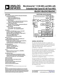
MicroConverter ® Technical Note - <strong>uC002</strong><br />
<strong>Develop<strong>in</strong>g</strong> <strong>in</strong> C <strong>with</strong> <strong>the</strong> <strong>Keil</strong> <strong>uVision2</strong> <strong>IDE</strong>.<br />
INTRODUCTION<br />
This technical note describes <strong>the</strong> use of <strong>the</strong> <strong>Keil</strong> <strong>uVision2</strong> Integrated Development Environment <strong>in</strong> <strong>the</strong><br />
development of a ‘C’ based, MicroConverter application.<br />
The <strong>Keil</strong> 8052 compiler package <strong>in</strong>cludes <strong>uVision2</strong> which is an Integrated Development Environment (<strong>IDE</strong>)<br />
along <strong>with</strong> all <strong>the</strong> utilities you may need to create embedded application programs for <strong>the</strong> MicroConverter family.<br />
An evaluation copy of <strong>the</strong> <strong>Keil</strong> C51 developers kit (PK51) is available as part of MicroConverter tools cha<strong>in</strong> or<br />
directly from <strong>the</strong> <strong>Keil</strong> web-site at http::\www.keil.com. This evaluation copy will create applications that are<br />
2Kbytes and smaller. You may use it to create and test your own target programs and also to evaluate <strong>the</strong> <strong>Keil</strong><br />
environment.<br />
CREATING A PROJECT<br />
Before writ<strong>in</strong>g any C-code, a project associated <strong>with</strong> our code needs to be created. This is done by first creat<strong>in</strong>g a new<br />
folder <strong>in</strong> <strong>the</strong> <strong>Keil</strong> directory <strong>in</strong> which your project will be saved. Next <strong>the</strong> <strong>Keil</strong> uV2 application can be launched and a new<br />
project is created. This is achieved by complet<strong>in</strong>g <strong>the</strong> follow<strong>in</strong>g steps.<br />
• Create a folder named Demo_ADuC <strong>in</strong> this path : c:\keil\c51\examples\<br />
• Launch <strong>the</strong> uV2 application. Start -> Programs -> <strong>Keil</strong>uvision2<br />
• Create a new project. From <strong>the</strong> ma<strong>in</strong> w<strong>in</strong>dow, choose <strong>the</strong> ‘Project’ menu and select ‘New project…’. A new w<strong>in</strong>dow<br />
appears as shown below <strong>in</strong> Figure 1.<br />
• Select <strong>the</strong> folder that you've created previously ( Demo_ADuC ) and on <strong>the</strong> bottom of <strong>the</strong> w<strong>in</strong>dow type <strong>the</strong> name of<br />
your new project, eg. Demo_ADuC and press SAVE.<br />
Figure 1.<br />
MicroConverter Tech Note – <strong>uC002</strong><br />
Ver 2.0 November 2001 - 1 - www.analog.com/microconverter
a<br />
MicroConverter ® Technical Note - <strong>uC002</strong><br />
<strong>Develop<strong>in</strong>g</strong> <strong>in</strong> C <strong>with</strong> <strong>the</strong> <strong>Keil</strong> <strong>uVision2</strong> <strong>IDE</strong>.<br />
A new w<strong>in</strong>dow appears as shown <strong>in</strong> figure 2 below and you are now required to configure your setup to target <strong>the</strong> specific<br />
MicroConverter device you wish to use (<strong>in</strong> this example we will be us<strong>in</strong>g <strong>the</strong> ADuC834) and <strong>the</strong> output file format<br />
generated after <strong>the</strong> compilation stage. This is achieved by complet<strong>in</strong>g <strong>the</strong> follow<strong>in</strong>g steps.<br />
• Open <strong>the</strong> ADI folder.<br />
• Select <strong>the</strong> MicroConverter on which you will be develop<strong>in</strong>g, <strong>in</strong> this tech note we will be us<strong>in</strong>g <strong>the</strong> ADuC834 as <strong>the</strong><br />
target example.<br />
Figure 2.<br />
MicroConverter Tech Note – <strong>uC002</strong><br />
Ver 2.0 November 2001 - 2 - www.analog.com/microconverter
a<br />
MicroConverter ® Technical Note - <strong>uC002</strong><br />
<strong>Develop<strong>in</strong>g</strong> <strong>in</strong> C <strong>with</strong> <strong>the</strong> <strong>Keil</strong> <strong>uVision2</strong> <strong>IDE</strong>.<br />
Next, you need to configure your target output options. This is done by click<strong>in</strong>g on <strong>the</strong> “options for target” item located <strong>in</strong><br />
<strong>the</strong> “project” pull-down menu. Alternatively you can select this option by click<strong>in</strong>g on <strong>the</strong> icon from <strong>the</strong> ‘compile’ toolbar<br />
situated at <strong>the</strong> top of <strong>the</strong> screen and shown <strong>in</strong> figure 3 below.<br />
Figure 3.<br />
‘Options for Target’<br />
Icon<br />
A new w<strong>in</strong>dow appears as shown <strong>in</strong> figure 4. Enable <strong>the</strong> option to Create Hex File by tick<strong>in</strong>g <strong>the</strong> check-box and press<strong>in</strong>g<br />
‘OK’ as shown circled <strong>in</strong> figure 4 below.<br />
Figure 4.<br />
MicroConverter Tech Note – <strong>uC002</strong><br />
Ver 2.0 November 2001 - 3 - www.analog.com/microconverter
a<br />
MicroConverter ® Technical Note - <strong>uC002</strong><br />
<strong>Develop<strong>in</strong>g</strong> <strong>in</strong> C <strong>with</strong> <strong>the</strong> <strong>Keil</strong> <strong>uVision2</strong> <strong>IDE</strong>.<br />
CREATING A C PROGRAM<br />
Now you can beg<strong>in</strong> writ<strong>in</strong>g your C program. In <strong>the</strong> ma<strong>in</strong> w<strong>in</strong>dow, choose <strong>the</strong> File pull-down menu and select<br />
New. A new w<strong>in</strong>dow named will appear on <strong>the</strong> screen. Type <strong>the</strong> C source code that is <strong>in</strong>cluded <strong>in</strong><br />
Appendix A of this tech note <strong>in</strong>to <strong>the</strong> w<strong>in</strong>dow.<br />
Once you've typed all <strong>the</strong> code, aga<strong>in</strong> choose <strong>the</strong> File pull-down menu and select Save. A new Save dialog<br />
w<strong>in</strong>dow appears. Save your new file as Demo_ADuC.c <strong>in</strong> <strong>the</strong> Demo_ADuC folder you had created earlier.<br />
At this stage, before compil<strong>in</strong>g <strong>the</strong> C-program, we need to <strong>in</strong>clude it <strong>in</strong> our project. To do this you must click <strong>with</strong><br />
<strong>the</strong> right mouse button on ‘Source Group 1’and select Add Files to Group ‘Source Group 1’ as shown <strong>in</strong> figure 5.<br />
Select <strong>the</strong> Demo_ADuC.c file that is <strong>in</strong> <strong>the</strong> Demo_ADuC folder and click on Add and <strong>the</strong>n on Close.<br />
Figure 5.<br />
MicroConverter Tech Note – <strong>uC002</strong><br />
Ver 2.0 November 2001 - 4 - www.analog.com/microconverter
a<br />
MicroConverter ® Technical Note - <strong>uC002</strong><br />
<strong>Develop<strong>in</strong>g</strong> <strong>in</strong> C <strong>with</strong> <strong>the</strong> <strong>Keil</strong> <strong>uVision2</strong> <strong>IDE</strong>.<br />
COMPILING A C PROGRAM<br />
Our C code is compiled by select<strong>in</strong>g ‘Build Target’ from <strong>the</strong> Project pull-down menu on <strong>the</strong> ma<strong>in</strong> tool-bar. The<br />
compile option can also be <strong>in</strong>itiated by select<strong>in</strong>g <strong>the</strong> ‘F7’ special function key or by click<strong>in</strong>g on <strong>the</strong> ‘Build Target’<br />
icon <strong>in</strong> <strong>the</strong> compile toolbar as shown <strong>in</strong> figure 6 below.<br />
Figure 6.<br />
If <strong>the</strong> compilation completes successfully a message <strong>in</strong>dicat<strong>in</strong>g that <strong>the</strong> compile job has completed <strong>with</strong> 0 errors<br />
will appear <strong>in</strong> <strong>the</strong> build dialog screen. Sometimes warn<strong>in</strong>gs may be generated for <strong>in</strong>formation purposes to <strong>in</strong>dicate<br />
multiple function calls etc. At this time, all <strong>the</strong> files that you need have been created <strong>in</strong> <strong>the</strong> Demo_ADuC folder.<br />
Chief among <strong>the</strong>se files are :<br />
Demo_ADuC.hex : The Intel-Standard, hex-file used when download<strong>in</strong>g code to <strong>the</strong> part <strong>in</strong>-circuit via <strong>the</strong><br />
serial port<br />
Demo_ADuC : This output file, generated <strong>with</strong>out a suffix is used <strong>in</strong> C-Source hardware debug sessions.<br />
If <strong>the</strong> resultant compilation message <strong>in</strong>dicates that <strong>the</strong>re were 1 or more errors, <strong>the</strong>n <strong>the</strong> output files will not be<br />
created. In this case, <strong>the</strong> file has been entered <strong>in</strong>correctly and click<strong>in</strong>g directly on any error message forces<br />
<strong>uVision2</strong> to highlight where <strong>in</strong> <strong>the</strong> code <strong>the</strong> error has occurred.<br />
SIMULATING YOUR C-SOURCE CODE<br />
Ano<strong>the</strong>r powerful feature of <strong>the</strong> <strong>uVision2</strong> <strong>IDE</strong> is that it allows you to run your code <strong>in</strong> a MicroConverter specific<br />
simulation environment. To start a simulation session you simply click on <strong>the</strong> on ‘Start/Stop Debug Session’<br />
option available from <strong>the</strong> ‘Debug’ pull-down menu. Alternatively you can press or <strong>the</strong> ‘Debug’ icon<br />
available <strong>in</strong> <strong>the</strong> ‘File’ toolbar as shown <strong>in</strong> figure 7.<br />
Figure 7.<br />
MicroConverter Tech Note – <strong>uC002</strong><br />
Ver 2.0 November 2001 - 5 - www.analog.com/microconverter
a<br />
MicroConverter ® Technical Note - <strong>uC002</strong><br />
<strong>Develop<strong>in</strong>g</strong> <strong>in</strong> C <strong>with</strong> <strong>the</strong> <strong>Keil</strong> <strong>uVision2</strong> <strong>IDE</strong>.<br />
CREATING THE SIMULATION ENVIRONMENT<br />
The follow<strong>in</strong>g steps will allow you to create a generic simulation environment that you may want to fur<strong>the</strong>r<br />
customize to your own requirements. From <strong>the</strong> top Debug toolbar, click on <strong>the</strong> icon buttons that are shown <strong>in</strong><br />
figure 8 below which open a Serial I/O peripheral w<strong>in</strong>dow as well as a code Performance Analyzer w<strong>in</strong>dow. Note:<br />
If <strong>the</strong> ‘Debug’ toolbar does not appear at <strong>the</strong> top of <strong>the</strong> screen, simply select <strong>the</strong> ‘Debug Toolbar’ option available<br />
from <strong>the</strong> ‘View’ pull-down menu.<br />
Figure 8.<br />
The various MicroConverter peripherals supported <strong>in</strong> <strong>the</strong> <strong>uVision2</strong> simulation environment can be selected from<br />
<strong>the</strong> ‘Peripherals’ pull-down menu. The Port3 peripheral is selected by click<strong>in</strong>g on Port3 from <strong>the</strong> ‘Peripherals’ -><br />
‘I/O Ports’ option. In this example we will be us<strong>in</strong>g Port 3 to simulate external <strong>in</strong>terrupts.<br />
Re-arrange <strong>the</strong> active w<strong>in</strong>dows as shown <strong>in</strong> figure 9 below.<br />
1 2<br />
Figure 9.<br />
MicroConverter Tech Note – <strong>uC002</strong><br />
Ver 2.0 November 2001 - 6 - www.analog.com/microconverter
a<br />
MicroConverter ® Technical Note - <strong>uC002</strong><br />
<strong>Develop<strong>in</strong>g</strong> <strong>in</strong> C <strong>with</strong> <strong>the</strong> <strong>Keil</strong> <strong>uVision2</strong> <strong>IDE</strong>.<br />
CONFIGURING THE PERFORMANCE ANALYZER<br />
Before we go any fur<strong>the</strong>r we first need to configure <strong>the</strong> Performance Analyzer (PA). This is done simply by right<br />
click<strong>in</strong>g on <strong>the</strong> PA and select<strong>in</strong>g <strong>the</strong> ‘Setup PA’ option. In <strong>the</strong> resultant dialog box, double click on each function<br />
symbol and press ‘Def<strong>in</strong>e’ <strong>in</strong> turn. Once this operation is completed for each function symbol, press ‘Close’ and<br />
<strong>the</strong> PA w<strong>in</strong>dow should now be configured as shown <strong>in</strong> figure 10.<br />
Figure 10.<br />
BASIC CODE FLOW<br />
The Demo_ADuC.C code cont<strong>in</strong>uously writes a l<strong>in</strong>ear ramp of 16 bytes to an <strong>in</strong>ternal RAM space on <strong>the</strong><br />
MicroConverter. Each time a byte is written to <strong>in</strong>ternal RAM, P3.4 is toggled (P3.4 drives an external led on <strong>the</strong><br />
MicroConverter Applications Board). If an external <strong>in</strong>terrupt INT0 is simulated by toggl<strong>in</strong>g <strong>the</strong> P3.2 bit <strong>in</strong> <strong>the</strong><br />
Port3 w<strong>in</strong>dow, <strong>the</strong> code vectors to <strong>the</strong> <strong>in</strong>terrupt_0 function ; <strong>the</strong> 16 values <strong>in</strong> <strong>the</strong> RAM are transmitted via <strong>the</strong><br />
UART and <strong>the</strong> will not return to <strong>the</strong> ma<strong>in</strong> rout<strong>in</strong>e until P3.2 has been manually cleared. After each <strong>in</strong>terrupt <strong>the</strong><br />
delay between P3.2 toggles is <strong>in</strong>creased because of <strong>the</strong> <strong>in</strong>crement <strong>in</strong> <strong>the</strong> ‘loop’ variable.<br />
STARTING THE SIMULATION SESSION<br />
To start <strong>the</strong> simulation, click on <strong>the</strong> GO icon <strong>in</strong> <strong>the</strong> DEBUG toolbar as shown <strong>in</strong> figure 11.<br />
Figure 11.<br />
MicroConverter Tech Note – <strong>uC002</strong><br />
Ver 2.0 November 2001 - 7 - www.analog.com/microconverter
a<br />
MicroConverter ® Technical Note - <strong>uC002</strong><br />
<strong>Develop<strong>in</strong>g</strong> <strong>in</strong> C <strong>with</strong> <strong>the</strong> <strong>Keil</strong> <strong>uVision2</strong> <strong>IDE</strong>.<br />
Immediately you will see <strong>the</strong> serial I/O w<strong>in</strong>dow be<strong>in</strong>g updated <strong>with</strong> <strong>the</strong> data be<strong>in</strong>g transmitted by <strong>the</strong><br />
MicroConverter UART <strong>in</strong> this simulation session and you should also note that <strong>the</strong> performance analyzer is be<strong>in</strong>g<br />
updated to reflect where code execution is spend<strong>in</strong>g most of its time (<strong>in</strong> this case, <strong>in</strong> <strong>the</strong> ma<strong>in</strong> rout<strong>in</strong>e) as shown <strong>in</strong><br />
figure 12.<br />
Figure 12.<br />
MicroConverter Tech Note – <strong>uC002</strong><br />
Ver 2.0 November 2001 - 8 - www.analog.com/microconverter
a<br />
MicroConverter ® Technical Note - <strong>uC002</strong><br />
<strong>Develop<strong>in</strong>g</strong> <strong>in</strong> C <strong>with</strong> <strong>the</strong> <strong>Keil</strong> <strong>uVision2</strong> <strong>IDE</strong>.<br />
SIMULATING AN EXTERNAL INTERRUPT<br />
Next, an external <strong>in</strong>terupt0 can be simulated by clear<strong>in</strong>g <strong>the</strong> P3.2 bit <strong>in</strong> <strong>the</strong> Port w<strong>in</strong>dow as shown <strong>in</strong> figure 13.<br />
Figure 13.<br />
In response to <strong>the</strong> simulated <strong>in</strong>terrupt, <strong>the</strong> 16 values <strong>in</strong> <strong>the</strong> RAM are transmitted via <strong>the</strong> UART and code<br />
execution will not return from <strong>the</strong> Interrupt Service Rout<strong>in</strong>e (ISR) until you reset <strong>the</strong> P3.2. Aga<strong>in</strong> before you clear<br />
<strong>the</strong> P3.2 bit you should note that <strong>the</strong> performance analyzer changes to reflect how <strong>the</strong> code is now wait<strong>in</strong>g <strong>in</strong> <strong>the</strong><br />
INT0 ISR as shown <strong>in</strong> figure 14.<br />
Figure 14.<br />
CONCLUSION<br />
This application note is a start<strong>in</strong>g po<strong>in</strong>t <strong>in</strong> <strong>the</strong> use of <strong>the</strong> <strong>uVision2</strong> <strong>IDE</strong> from <strong>Keil</strong>. <strong>uVision2</strong> is a powerful means to<br />
develop your MicroConverter application <strong>in</strong> assembly or high level C. There are many aspects <strong>in</strong> <strong>the</strong> uvision2 tool<br />
suite; this application note illustrated some of <strong>the</strong>m. The code compiled and simulated <strong>in</strong> this tech-note can be<br />
downloaded directly on <strong>the</strong> ADuC834 QuickStart TM evaluation board us<strong>in</strong>g <strong>the</strong> W<strong>in</strong>dows Serial Downloader<br />
(WSD) application.<br />
MicroConverter Tech Note – <strong>uC002</strong><br />
Ver 2.0 November 2001 - 9 - www.analog.com/microconverter
a<br />
MicroConverter ® Technical Note - <strong>uC002</strong><br />
<strong>Develop<strong>in</strong>g</strong> <strong>in</strong> C <strong>with</strong> <strong>the</strong> <strong>Keil</strong> <strong>uVision2</strong> <strong>IDE</strong>.<br />
APPENDIX A : DEMO_ADuC CODE LISTING<br />
//DEMO_ADuC.c - This Program writes a l<strong>in</strong>ear ramp of 16 bytes to<br />
// <strong>in</strong>ternal RAM on <strong>the</strong> MicroConverter. Each time a<br />
// byte is written <strong>the</strong> P3.4 I/O p<strong>in</strong> is toggled.<br />
// P3.4 drives an external LED on all MicroConverter<br />
// Application Boards. In response to an external<br />
// <strong>in</strong>terrupt (INT0), <strong>the</strong> program transmits <strong>the</strong> <strong>in</strong>ternal<br />
// RAM data bytes via <strong>the</strong> UART serial port at 9600 Baud<br />
//<br />
// Note this rout<strong>in</strong>e can be tailored to any<br />
// MicroConverter device by simply chang<strong>in</strong>g <strong>the</strong> header<br />
// file <strong>in</strong>clude directive at <strong>the</strong> beg<strong>in</strong>n<strong>in</strong>g of <strong>the</strong><br />
// rout<strong>in</strong>e below.<br />
//<br />
//======================================================================<br />
#<strong>in</strong>clude <br />
#<strong>in</strong>clude <br />
<strong>in</strong>t loop=0, c=0;<br />
unsigned char memory[16];<br />
// Standard I/O Functions<br />
// ADuC834 Header File<br />
// global loop and <strong>in</strong>dex variables<br />
// memory array of chars<br />
void <strong>in</strong>terrupt_0 () <strong>in</strong>terrupt 0 // INT0 ISR def<strong>in</strong>ed here<br />
{<br />
for ( c = 0 ; c < 16; c++) // Cycle through <strong>in</strong>ternal RAM<br />
{<br />
pr<strong>in</strong>tf ("%02BD\n",memory[c]); // Transmit RAM via UART<br />
}<br />
pr<strong>in</strong>tf ("\n"); // Transmit <br />
loop++;<br />
// Increment loop variable so <strong>the</strong> LED<br />
// will flash at a slower rate<br />
while(INT0 != 1); // Wait until P3.2 p<strong>in</strong> is reset<br />
}<br />
void wait (void) {<br />
// wait function<br />
; // only to delay for LED flashes<br />
}<br />
void ma<strong>in</strong>(void)<br />
{<br />
<strong>in</strong>t a=0, b=0;<br />
<strong>in</strong>t i=0, j=0;<br />
// loop variables<br />
// memory <strong>in</strong>dex variables<br />
// Configure UART for 9600 baud comms<br />
MicroConverter Tech Note – <strong>uC002</strong><br />
Ver 2.0 November 2001 - 10 - www.analog.com/microconverter
a<br />
MicroConverter ® Technical Note - <strong>uC002</strong><br />
<strong>Develop<strong>in</strong>g</strong> <strong>in</strong> C <strong>with</strong> <strong>the</strong> <strong>Keil</strong> <strong>uVision2</strong> <strong>IDE</strong>.<br />
SCON = 0x52;<br />
// 8-Bit UART Mode<br />
T2CON = 0x30;<br />
// enable T2 <strong>in</strong> reload mode for TX and<br />
// RX UART Clk<br />
RCAP2H = 0xFF;<br />
// T2 hi-byte reload value<br />
RCAP2L = 0xFB;<br />
// T2 lo-byte reload value<br />
TH2 = 0xFF;<br />
// T2 hi-byte <strong>in</strong>itial value<br />
TL2 = 0xFB;<br />
// T2 lo-byte <strong>in</strong>itial value<br />
TR2 = 1; // Run Timer 2<br />
TCON |= 0x01 ;<br />
IE |= 0x80 ;<br />
IE |= 0x01 ;<br />
// Configure INT0<br />
// enable INTO <strong>in</strong>terrupt as edge<br />
// triggered <strong>in</strong>put<br />
// enable global <strong>in</strong>terrupts, Set EA Bit<br />
// enable INTO, Set EX0 bit<br />
while(1)<br />
// Loop Forever<br />
{<br />
pr<strong>in</strong>tf (" Updat<strong>in</strong>g Internal Memory <strong>with</strong> Ramp Number: %d\n", j);<br />
// Transmit Ramp <strong>in</strong>dication update via<br />
// UART Serial Port<br />
}<br />
}<br />
for ( i = 0 ; i < 16; i++) // L<strong>in</strong>ear Ramp<br />
{<br />
for (a = 0; a < 1000; a++) // Delay for 1000 Counts<br />
{<br />
for (b = 0; b