XAPP112: Designing With XC9500XL CPLDs - App Note, V1.1 (01/99)
XAPP112: Designing With XC9500XL CPLDs - App Note, V1.1 (01/99)
XAPP112: Designing With XC9500XL CPLDs - App Note, V1.1 (01/99)

Create successful ePaper yourself
Turn your PDF publications into a flip-book with our unique Google optimized e-Paper software.
APPLICATION NOTE<br />
®<br />
1<br />
<strong>Designing</strong><br />
<strong>With</strong> <strong>XC9500XL</strong> <strong>CPLDs</strong><br />
<strong>XAPP112</strong> January 22, 1<strong>99</strong>9 (Version 1.1)<br />
<strong>App</strong>lication <strong>Note</strong><br />
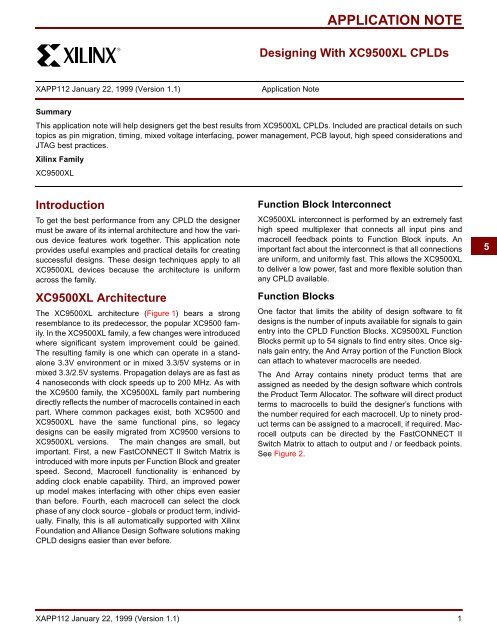
Summary<br />
This application note will help designers get the best results from <strong>XC9500XL</strong> <strong>CPLDs</strong>. Included are practical details on such<br />
topics as pin migration, timing, mixed voltage interfacing, power management, PCB layout, high speed considerations and<br />
JTAG best practices.<br />
Xilinx Family<br />
<strong>XC9500XL</strong><br />
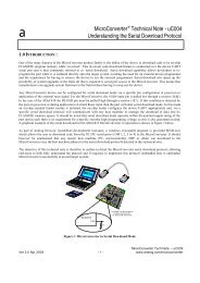
Introduction<br />
To get the best performance from any CPLD the designer<br />
must be aware of its internal architecture and how the various<br />
device features work together. This application note<br />
provides useful examples and practical details for creating<br />
successful designs. These design techniques apply to all<br />
<strong>XC9500XL</strong> devices because the architecture is uniform<br />
across the family.<br />
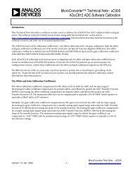
<strong>XC9500XL</strong> Architecture<br />
The <strong>XC9500XL</strong> architecture (Figure 1) bears a strong<br />
resemblance to its predecessor, the popular XC9500 family.<br />
In the <strong>XC9500XL</strong> family, a few changes were introduced<br />
where significant system improvement could be gained.<br />
The resulting family is one which can operate in a standalone<br />
3.3V environment or in mixed 3.3/5V systems or in<br />
mixed 3.3/2.5V systems. Propagation delays are as fast as<br />
4 nanoseconds with clock speeds up to 200 MHz. As with<br />
the XC9500 family, the <strong>XC9500XL</strong> family part numbering<br />
directly reflects the number of macrocells contained in each<br />
part. Where common packages exist, both XC9500 and<br />
<strong>XC9500XL</strong> have the same functional pins, so legacy<br />
designs can be easily migrated from XC9500 versions to<br />
<strong>XC9500XL</strong> versions. The main changes are small, but<br />
important. First, a new FastCONNECT II Switch Matrix is<br />
introduced with more inputs per Function Block and greater<br />
speed. Second, Macrocell functionality is enhanced by<br />
adding clock enable capability. Third, an improved power<br />
up model makes interfacing with other chips even easier<br />
than before. Fourth, each macrocell can select the clock<br />
phase of any clock source - globals or product term, individually.<br />
Finally, this is all automatically supported with Xilinx<br />
Foundation and Alliance Design Software solutions making<br />
CPLD designs easier than ever before.<br />
Function Block Interconnect<br />
<strong>XC9500XL</strong> interconnect is performed by an extremely fast<br />
high speed multiplexer that connects all input pins and<br />
macrocell feedback points to Function Block inputs. An<br />
important fact about the interconnect is that all connections<br />
are uniform, and uniformly fast. This allows the <strong>XC9500XL</strong><br />
to deliver a low power, fast and more flexible solution than<br />
any CPLD available.<br />
Function Blocks<br />
One factor that limits the ability of design software to fit<br />
designs is the number of inputs available for signals to gain<br />
entry into the CPLD Function Blocks. <strong>XC9500XL</strong> Function<br />
Blocks permit up to 54 signals to find entry sites. Once signals<br />
gain entry, the And Array portion of the Function Block<br />
can attach to whatever macrocells are needed.<br />
The And Array contains ninety product terms that are<br />
assigned as needed by the design software which controls<br />
the Product Term Allocator. The software will direct product<br />
terms to macrocells to build the designer’s functions with<br />
the number required for each macrocell. Up to ninety product<br />
terms can be assigned to a macrocell, if required. Macrocell<br />
outputs can be directed by the FastCONNECT II<br />
Switch Matrix to attach to output and / or feedback points.<br />
See Figure 2.<br />
5<br />
<strong>XAPP112</strong> January 22, 1<strong>99</strong>9 (Version 1.1) 1
R<br />
<strong>Designing</strong> <strong>With</strong> <strong>XC9500XL</strong> <strong>CPLDs</strong><br />
JTAG Port<br />
3<br />
JTAG<br />
Controller<br />
In-System Programming Controller<br />
I/O<br />
I/O<br />
18<br />
54<br />
Function<br />
Block 1<br />
Macrocells<br />
1 to 18<br />
I/O<br />
I/O<br />
I/O<br />
I/O<br />
I/O<br />
I/O<br />
I/O/GCK<br />
I/O/GSR<br />
I/O/GTS<br />
3<br />
1<br />
2 or 4<br />
I/O<br />
Blocks<br />
Advanced Interconnect MATRIX<br />
FastConnect II Switch Matrix<br />
18<br />
18<br />
18<br />
54<br />
54<br />
54<br />
Function<br />
Block 2<br />
Macrocells<br />
1 to 18<br />
Function<br />
Block 3<br />
Macrocells<br />
1 to 18<br />
Function<br />
Block N<br />
Macrocells<br />
1 to 18<br />
Figure 1: <strong>XC9500XL</strong> Architecture<br />
X5877<br />
Macrocell 1<br />
From<br />
FastCONNECT II<br />
Switch Matrix<br />
54<br />
Programmable<br />
AND-Array<br />
Product<br />
Term<br />
Allocators<br />
18<br />
18<br />
OUT<br />
To FastCONNECT II<br />
Switch Matrix<br />
18<br />
PTOE<br />
To I/O Blocks<br />
Macrocell 18<br />
1<br />
3<br />
Global<br />
Set/Reset<br />
Global<br />
Clocks X5878_<strong>01</strong><br />
Figure 2: <strong>XC9500XL</strong> Function Block<br />
2 <strong>XAPP112</strong> January 22, 1<strong>99</strong>9 (Version 1.1)
R<br />
<strong>Designing</strong> <strong>With</strong> <strong>XC9500XL</strong> <strong>CPLDs</strong><br />
54<br />
Global<br />
Set/Reset<br />
Global<br />
Clocks<br />
3<br />
Additional<br />
Product<br />
Terms<br />
(from other<br />
macrocells)<br />
Product Term Set<br />
1<br />
0<br />
S<br />
D/T<br />
Q<br />
To<br />
FastCONNECTII<br />
Switch Matrix<br />
Product<br />
Term<br />
Allocator<br />
Product Term Clock Enable<br />
EC<br />
R<br />
Product Term Clock<br />
Product Term Reset<br />
OUT<br />
5<br />
Product Term OE<br />
PTOE<br />
To<br />
I/O Blocks<br />
Additional<br />
Product<br />
Terms<br />
(from other<br />
macrocells)<br />
<strong>99</strong><strong>01</strong>2002<br />
Figure 3: <strong>XC9500XL</strong> Macrocell<br />
The Macrocell<br />
In its native configuration, the <strong>XC9500XL</strong> macrocell<br />
(Figure 3) can be thought to have 5 product terms directly<br />
available to it. By appropriately importing unused neighboring<br />
product terms, the macrocell logic can “grow”. By<br />
exporting unused product terms to neighboring macrocells,<br />
the macrocell logic can “shrink”. Table 1 shows about how<br />
many product terms (P-Terms) are needed to form some<br />
common logic functions. When designing, this gives an<br />
idea of how many p-terms are used to create the various<br />
functions. Naturally, more operations exist than these,<br />
which can be found in the Xilinx Library documents.<br />
As shown in Figure 3, the macrocell is comprised of the<br />
product term allocator, several configuration multiplexers<br />
and a D/T type flip flop with clock enable. The five native<br />
product terms can be thought of as directly available at this<br />
macrocell site. In the native condition, each product term<br />
can be thought of as having at least three alternate configurations.<br />
Table 1: Macrocell/Product Term Usage<br />
Data Operation<br />
Shift Register<br />
P-Terms Used<br />
1 per bit<br />
Counters<br />
1 to 4 per bit<br />
N:1 Mux N<br />
2-Bit Adder 6<br />
Exclusive-OR 2<br />
Storage Register 1<br />
First, a p-term has a designated specialty function at a particular<br />
macrocell. This is the ability to form a product term<br />
output enable, a product term clock, a product term set,<br />
product term reset or drive one leg of the EX-OR gate. An<br />
alternate configuration for a product term is to participate in<br />
the local sum of products logic via the OR gate that drives<br />
one EX-OR input pin. If a product term does not contribute<br />
its specialty function at the macrocell, or participate in the<br />
local logic OR operation, then it is available to be collected<br />
by another OR and forwarded to a neighbor macrocell in<br />
either direction. This is termed cascading, and will be<br />
described in more detail later. Finally, the product term set<br />
<strong>XAPP112</strong> January 22, 1<strong>99</strong>9 (Version 1.1) 3
R<br />
<strong>Designing</strong> <strong>With</strong> <strong>XC9500XL</strong> <strong>CPLDs</strong><br />
and reset product terms can assume the functionality of<br />
driving the flip flop clock enable. Figure 4 shows details of<br />
Product Term Allocation and Figure 5 and Figure 6 show<br />
how clock enable circuitry is created.<br />
Product Term<br />
Allocator<br />
Product Term<br />
Allocator<br />
Macrocell Logic<br />
<strong>With</strong> 2<br />
Product Terms<br />
In Figure 4, all but the Product Term Allocators have been<br />
omitted for clarity. In this situation, the design requirement<br />
is to deliver 18 product terms to the designated sum of<br />
product output site. The native set of 5 p-terms is supplemented<br />
with 5 p-terms from each directly adjacent neighbor<br />
taking the tally to 15 product terms. In this case, three more<br />
p-terms are needed, so the software must find them. The<br />
next site (to the north) requires two of its native 5 product<br />
terms, but three are available to meet the demand. The<br />
software forwards the available three p-terms to the<br />
required delivery site. In this case, two cascade times are<br />
required to provide 18 product terms. <strong>Note</strong> that the solution<br />
is not unique. The software could just as well encounter an<br />
adjacent neighbor with locked down product terms and<br />
been forced to skip over another macrocell to satisfy its<br />
need. The bidirectional cascade permits passing to/from<br />
both directions, which increases the likelihood of finding<br />
needed logic. This typically gives results within a single<br />
cascade and occasionally needs to go further. Product<br />
terms are located circularly so that the bottom macrocell<br />
can pass directly to the top macrocell and vice versa. An<br />
important factor here is that every macrocell has the same<br />
potential access to product terms.<br />
Product Term<br />
Allocator<br />
D/T<br />
EC<br />
><br />
S<br />
R<br />
Q<br />
To Out<br />
Figure 5: D/T Flip Flop Clock Enable Notation<br />
Product Term<br />
Allocator<br />
Figure 4: Product Term Allocation<br />
Macrocell Logic<br />
<strong>With</strong> 18<br />
Product Terms<br />
X5896<br />
D<br />
CE<br />
S<br />
D/T Q<br />
><br />
Figure 6: D/T Flip Flop Clock Enable Structure<br />
R<br />
To FastCONNECT<br />
To Out<br />
In Figure 5, the Flip Flop shows separate D/T and EC<br />
(clock enable) pins attached to the flop. Actually, the term<br />
clock enable is a misnomer, because as shown in Figure 6,<br />
it is simply a mux select pin that chooses between an external<br />
“D” pin and the flop's own Q output. Clock enable does<br />
introduce an additional control pin to be managed, but is<br />
often used in cases where designers would otherwise be<br />
tempted to gate the clock to obtain design control.<br />
Not emphasized in the macrocell diagram is the ability to<br />
selectively invert any clock entering the clock mux before<br />
attaching to the flip flop clock input point. Figure 7 details<br />
how this is achieved at every macrocell site.<br />
4 <strong>XAPP112</strong> January 22, 1<strong>99</strong>9 (Version 1.1)
R<br />
<strong>Designing</strong> <strong>With</strong> <strong>XC9500XL</strong> <strong>CPLDs</strong><br />
GCKs<br />
Pterm Clock<br />
S<br />
D/T Q<br />
EC<br />
><br />
Figure 7: Macrocell Clock Inversion Selection<br />
<strong>XC9500XL</strong> Pin Migration Capability<br />
Table 2 shows the pin compatibility among <strong>XC9500XL</strong><br />
devices. Designs can be easily migrated to larger and<br />
smaller devices. In many cases greater density with equivalent<br />
speed can be obtained by using larger parts. If a<br />
design is initially targeted to a smaller device, the same<br />
design can be easily moved into a larger device, if more<br />
R<br />
capacity is required. This capability allows designers to<br />
maintain their pin assignments when designs must be<br />
moved to a larger device. Moving designs from larger to<br />
smaller devices can also be accomplished, while keeping<br />
the original pinout, if the smaller device has enough<br />
resources to contain the design.<br />
A reasonable design practice would be to pick the lowest<br />
capacity for a given package in the slowest speed grade.<br />
Then, as design proceeds, larger or faster parts can accept<br />
the design as expectations and/or needs change. Picking<br />
the slowest and least dense part would economically be the<br />
best first choice, anyway. The key is to first pick the one<br />
closest to your needs. This approach would be somewhat<br />
different, if future field upgrade was a consideration,<br />
because here it might be appropriate to “over spec” a part<br />
to include speed latitude and additional available function<br />
for unforeseen future changes.<br />
Table 2: <strong>XC9500XL</strong> Available Packages and Device I/O Pins<br />
XC9536XL XC9572XL XC95144XL XC95288XL<br />
44-Pin PLCC 34 34<br />
64-Pin VQFP 36 52<br />
100-Pin TQFP 72 81<br />
144-Pin TQFP 117 117<br />
208-Pin PQFP 168<br />
48-Pin CSP 36 38<br />
144-Pin CSP 117<br />
352-Pin BGA 192<br />
5<br />
<strong>XC9500XL</strong> Timing Model<br />
The <strong>XC9500XL</strong> Timing Model is shown in Figure 8. This<br />
type of diagram exposes the architecture of an <strong>XC9500XL</strong><br />
part in a way that each encountered time delay is shown.<br />
Table 3 summarizes the individual time delays found. The<br />
parameters identified in Table 3 are present in the fitter<br />
report for a particular design. This lets a designer identify<br />
exactly how their design's performance is determined by<br />
simply tallying the delays incurred as each signal visits the<br />
various internal part functions. For instance, tPD is determined<br />
in the simplest configuration as:<br />
t PD = t IN + t LOGI + t PDI + t OUT<br />
Other paths are easily identified and more examples are<br />
provided in the <strong>XC9500XL</strong> Timing <strong>App</strong>lication <strong>Note</strong>. (See<br />
Xilinx application note number XAPP111 - Using the<br />
XC9500 Timing Model.)<br />
<strong>XAPP112</strong> January 22, 1<strong>99</strong>9 (Version 1.1) 5
R<br />
<strong>Designing</strong> <strong>With</strong> <strong>XC9500XL</strong> <strong>CPLDs</strong><br />
t F<br />
t IN<br />
t GCK<br />
t GSR<br />
t LOGILP<br />
t LOGI<br />
S*t PTA<br />
D/T<br />
t PDI<br />
Q<br />
t SLEW<br />
t OUT<br />
t SUI t COI<br />
t<br />
t HI<br />
PTCK<br />
EC t AOI<br />
t<br />
> t ECHO<br />
t RAI<br />
EN<br />
t PTSR<br />
t<br />
SR<br />
ECSUI<br />
t PTTS<br />
Macrocell<br />
t GTS<br />
Figure 8: <strong>XC9500XL</strong> Timing Model<br />
Table 3: Timing Parameters<br />
Parameter<br />
t AOI<br />
t COI<br />
t E<br />
t ECHO<br />
t ECSUI<br />
t GCK<br />
t GSR<br />
t GTS<br />
t HI<br />
t IN<br />
t LOGI<br />
t LOGILP<br />
t OU<br />
t PDI<br />
t PTA<br />
t PTC<br />
t PTTS<br />
t RAI<br />
t SLEW<br />
t SUI<br />
Practical Considerations<br />
Power On Model<br />
Name<br />
Register asynchronous S/R to output delay<br />
Resister clock to output valid delay<br />
Output tri-state enable time<br />
Enable clock hold time<br />
Enable clock setup time<br />
GCK buffer delay<br />
GSR buffer delay<br />
GTS buffer delay<br />
Register hold time<br />
Input buffer delay<br />
Internal logic delay<br />
Internal low power logic delay<br />
Output buffer time delay<br />
Combinatorial logic propagation delay<br />
Incremental product term allocator delay<br />
Product term clock delay<br />
Product term tri-state delay<br />
Register asynchronous S/R recovery before clock<br />
Slew rate limited delay<br />
Register setup time<br />
<strong>XC9500XL</strong> parts are designed to provide a flexible voltage<br />
environment for today’s demanding voltage environments.<br />
Key to this is considering lots of details that permit designers<br />
the choice of speeds and densities, but automatically<br />
handle electrical issues that are frequently overlooked by<br />
others. First on the list is a flexible “Power On Model”.<br />
Figure 9 shows how an <strong>XC9500XL</strong> powers up. In this diagram,<br />
we will assume V CCINT and V CCIO are either tied<br />
together or rising together. In this case, as V CC rises, the<br />
pins are assumed initially to be in high impedance condition,<br />
with large pullup resistance to V CCINT . This provides a<br />
logic high that can be easily counter driven by a pin from an<br />
external chip wishing to dominate that electrical point. At<br />
one point in the power up process, the <strong>XC9500XL</strong> passes<br />
its internal configuration bits to the parts functional<br />
resources and the outputs are configured as dictated by the<br />
programming pattern. When the part is powered down,<br />
small keeper circuits retain the last value the pins drove as<br />
VCC drops. Some variation occurs if V CCIO is cycled separately,<br />
but in all cases, the most benign electrical state is<br />
assumed.<br />
Outputs as configured<br />
Outputs HIGHZ, pulled up<br />
First time power up<br />
Figure 9: Power Up Model<br />
Outputs follow<br />
last value (assuming<br />
V CCIO is still up here)<br />
6 <strong>XAPP112</strong> January 22, 1<strong>99</strong>9 (Version 1.1)
R<br />
Mixed Voltage Operation<br />
<strong>XC9500XL</strong> I/Os are designed to deliver output signals that<br />
range from 0 to 3.3V (+/- 10%). Figure 10 details the separation<br />
between V CCINT and V CCIO and shows the CMOS<br />
output buffer. Figure 11 and Figure 12 show operation with<br />
<strong>Designing</strong> <strong>With</strong> <strong>XC9500XL</strong> <strong>CPLDs</strong><br />
mixed voltages. Table 4 summarizes the voltage compatibility<br />
of the <strong>XC9500XL</strong> and other logic families. Finally,<br />
Figure 13 shows the input hysteresis that improves noise<br />
margin for <strong>XC9500XL</strong> inputs.<br />
V CCINT = 3.3V<br />
VCCIO = 3.3V/2.5V<br />
V CCIO<br />
P<br />
CORE<br />
LOGIC<br />
N<br />
Figure 10: <strong>XC9500XL</strong> I/O Architecture and Output Structure<br />
5V<br />
3.3V<br />
5<br />
3.3V<br />
2.5V<br />
V CCIO<br />
V CCINT<br />
V CCIO<br />
V CCINT<br />
Any<br />
5V TTL<br />
device<br />
5V<br />
3.3V<br />
<strong>XC9500XL</strong><br />
3.3V<br />
3.3V<br />
Any<br />
3.3V<br />
device<br />
Any<br />
3.3V<br />
device<br />
3.3V<br />
2.5V<br />
<strong>XC9500XL</strong><br />
2.5V<br />
2.5V<br />
Any<br />
2.5V<br />
device<br />
Figure 11: Mixed Voltage 3.3/5V Operation<br />
Figure 12: Mixed Voltage 3.3/2.5V Operation<br />
Table 4: <strong>XC9500XL</strong> Voltage Compatibility Summary<br />
V OH<br />
5V CMOS 5V TTL 3.3V LVCMOS 3.3V LVTTL 2.5V Normal<br />
V IL X X X X X<br />
V IH X X X X X<br />
V OL X X X X X<br />
V OH 3.3V 3.3V X X X<br />
V OUT<br />
(Volts)<br />
V OL<br />
50mV<br />
1.40V 1.45V<br />
V IN (Volts)<br />
Figure 13: <strong>XC9500XL</strong> Input Hysteresis<br />
Power Management Considerations<br />
<strong>XC9500XL</strong> family parts provide substantial power reduction<br />
simply because the internal V CC ranges well below that<br />
of 5V CPLD families. Due to the square law relationship,<br />
this alone provides a nearly 60% reduction in power over<br />
5V families. However, internal options are provided to lower<br />
power even more. This includes the ability to operate each<br />
product term in a low power mode (at nominal speed reduction)<br />
and the ability to operate the I/O pins at 2.5V when<br />
appropriate.<br />
<strong>XAPP112</strong> January 22, 1<strong>99</strong>9 (Version 1.1) 7
R<br />
<strong>Designing</strong> <strong>With</strong> <strong>XC9500XL</strong> <strong>CPLDs</strong><br />
Optimizing Power<br />
The following guidelines will aid in reducing power consumed<br />
by an <strong>XC9500XL</strong> CPLD.<br />
1. Terminate unused Input pins. This guarantees they are<br />
not floating. A convenient way to do this is with the User<br />
Programmable Ground (UPG) feature.<br />
2. Assign High Speed only to those macrocells that absolutely<br />
require it. The remaining macrocells should be<br />
placed in low power mode.<br />
3. Eliminate or minimize slow slewing input signals. These<br />
signals require input buffers to remain in their conducting<br />
region for long periods.<br />
4. If possible, set V CCIO to the 2.5V level to limit the output<br />
voltage swing range and lower power in that section.<br />
Power Supply Sequencing<br />
Separate power supplies for V CC and V CCIO may be powered<br />
up or down in any sequence without harming an<br />
<strong>XC9500XL</strong> CPLD.<br />
High Speed Design Considerations<br />
Although <strong>XC9500XL</strong> parts are not prone to having signal<br />
quality issues, ground rise and signal reflections can be<br />
managed by planning. The following design guidelines<br />
should strongly be considered in advance to avoid difficulty<br />
when operating with lots of simultaneously switching signals<br />
and at high frequencies.<br />
1. Only connect the essential outputs to I/O pins. Intermediate<br />
shift register bits and counter bits that need not<br />
drive outputs should remain buried.<br />
2. Minimize the number of outputs switching simultaneously.<br />
3. Two global clock inputs can be managed by delaying<br />
one to introduce signal skew. Breaking long clock chains<br />
across multiple clock drivers can provide skew (less<br />
than 1 nanosecond) that can significantly reduce ground<br />
rise.<br />
4. Using additional ground pins can lower ground rise<br />
effects. Unused pins configured as User Programmable<br />
Grounds (UPG) can be tied directly to the PCB ground<br />
plane. This splits the current driven into heavily loaded<br />
ground pins and lowers the voltage rise. Best UPG<br />
placement is uniformly around the chip, if possible.<br />
5. Signal skewing can reduce ground rise. This can be<br />
achieved by mixing ordinary and fast slew rate outputs.<br />
Only assign fast slew rate to signals that require it.<br />
PC Board Layout Considerations<br />
Key to a good digital design is a good electrical design. The<br />
following checklist will be helpful to make sure practical<br />
oversights do not occur when creating a new printed circuit<br />
board. Most of these practices are typical of high speed<br />
microprocessor board design, so there should be no issue<br />
when using the same practices for <strong>XC9500XL</strong> CPLD<br />
designs.<br />
Layout Checklist<br />
1. Avoid floating inputs. Invoke User Programmable<br />
Ground if possible to deliver low driven output signal to<br />
internal input. For additional ground management,<br />
attach such pins to PCB ground.<br />
2. Locate <strong>XC9500XL</strong> parts near the devices they drive (or<br />
are driven by) to minimize transmission line effects.Use<br />
wide spacing between fast signal lines (particularly<br />
clocks) to minimize crosstalk.<br />
3. Place power pins (V CC and GND) on separate board<br />
planes. Fast signals should reside on a different plane,<br />
still.<br />
4. Decouple all device V CC pins with 0.1 µF and 0.<strong>01</strong> µF<br />
capacitors connected to the nearest ground plane. Low<br />
inductance surface mounted capacitors are recommended.<br />
Some designs may require different values.<br />
5. Decouple the printed circuit board power inputs with 0.1<br />
µF ceramic (high frequency) and 100 µF electrolytic (low<br />
frequency) filter capacitors.<br />
6. Connect all device ground pins together, to ground.<br />
7. Avoid using sockets to attach <strong>XC9500XL</strong> <strong>CPLDs</strong> to the<br />
PCB. Direct soldered connection minimizes inductance<br />
and reduces ground rise. <strong>XC9500XL</strong> <strong>CPLDs</strong> are specifically<br />
designed for direct PCB attachment.<br />
Pin Preassigning Guidelines<br />
Frequently, designers must layout their PCBs prior to the<br />
development of the design. Any commercially available<br />
CPLD will have difficulty keeping the pin assignment for a<br />
totally arbitrary design done with little or no forethought. As<br />
mentioned earlier, it is a good idea to always target a<br />
design to the lowest density available in a given package<br />
for the slowest speed grade available.<br />
If a legacy design can be used as a “comfortable” model,<br />
then it's pin assignment may be appropriate. In this case,<br />
having density and speed slack available is important. If no<br />
legacy design exists, spreading the pins uniformly so that<br />
available blank slots exist between pins will help assure<br />
available product terms will exist to handle future changes<br />
as the design proceeds. Remember, pin preassigning without<br />
having the software make a first pin assignment is not<br />
recommended. If at all possible, let the design software<br />
have a preliminary version of the design prior to producing<br />
a printed circuit board, to assure a reasonable first pinout<br />
has been obtained.<br />
8 January 22, 1<strong>99</strong>9 (Version 1.1)
R<br />
Boundary-Scan and ISP Capability<br />
<strong>XC9500XL</strong> <strong>CPLDs</strong> include a significant repertoire of IEEE<br />
std 1149.1testing and JTAG ISP instructions. Table 5 summarizes<br />
the set of instructions that might be encountered<br />
during a design. Others exist, which are proprietary to Xilinx<br />
<strong>CPLDs</strong>.<br />
Table 5: Supported JTAG & ISP Instructions and<br />
Affected Registers<br />
Instruction<br />
Bypass<br />
Clamp<br />
EXTEST<br />
FlashErase<br />
FlashProgram<br />
FlashVerify<br />
HIGHZ<br />
INTEST<br />
Sample/Preload<br />
Multi-voltage JTAG Capability<br />
JTAG Registers<br />
Bypass Register<br />
Bypass Register<br />
Boundary Scan Register<br />
Configuration Register<br />
Configuration Register<br />
Configuration Register<br />
Bypass Register<br />
Boundary Scan Register<br />
Boundary Scan Register<br />
<strong>XC9500XL</strong> <strong>CPLDs</strong> are designed specifically to operate in a<br />
multivoltage JTAG environment and maintain full signal and<br />
JTAG integrity. Internal pullup resistors are on TMS and<br />
TDI to 3.3V.<br />
ISP Checklist<br />
<strong>Designing</strong> <strong>With</strong> <strong>XC9500XL</strong> <strong>CPLDs</strong><br />
When programming an ISP CPLD, best results are<br />
obtained when common practices are used. The following<br />
checklist gives the standard points to observe to obtain<br />
best ISP results.<br />
1. Make sure V CCINT is within the rated value: 3.3V +/- 5%.<br />
2. Provide both 0.1 and 0.<strong>01</strong> µF capacitors at every V CC<br />
point of the chip, and attach directly to the nearest<br />
ground.<br />
3. Use the latest Xilinx download cables. This would be a<br />
Parallel Cable with serial numbers greater than 5000 or<br />
any X-Checker cable.<br />
4. Consider including buffers on TCK and TMS interleaved<br />
at various points on your JTAG circuitry to account for<br />
unknown device impedance.<br />
5. Always be certain to use the latest version of the Xilinx<br />
JTAG Programmer Software.<br />
6. Put the rest of the JTAG chain into HIGHZ when programming<br />
a troublesome part. This is optional.<br />
7. If free running clocks are delivered into the ISP CPLD, it<br />
may be necessary to disconnect or disable their entry<br />
into the CPLD while programming.<br />
8. For <strong>XC9500XL</strong> designs attach VCC from the parallel<br />
cable to 3.3V on the PCB.<br />
Conclusion<br />
<strong>XC9500XL</strong> <strong>CPLDs</strong> provide an abundance of logic<br />
resources and require only a minimum number of design<br />
considerations to obtain the best results. By carefully following<br />
the guidelines and checklists included here, designers<br />
can expect to obtain all the features needed in today’s<br />
high speed, low voltage systems.<br />
5<br />
<strong>XAPP112</strong> January 22, 1<strong>99</strong>9 (Version 1.1) 9