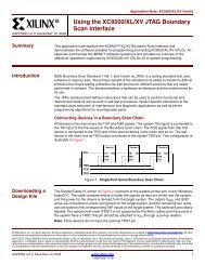
XAPP112: Designing With XC9500XL CPLDs - App Note, V1.1 (01/99)
XAPP112: Designing With XC9500XL CPLDs - App Note, V1.1 (01/99)
XAPP112: Designing With XC9500XL CPLDs - App Note, V1.1 (01/99)

Create successful ePaper yourself
Turn your PDF publications into a flip-book with our unique Google optimized e-Paper software.
R<br />
<strong>Designing</strong> <strong>With</strong> <strong>XC9500XL</strong> <strong>CPLDs</strong><br />
t F<br />
t IN<br />
t GCK<br />
t GSR<br />
t LOGILP<br />
t LOGI<br />
S*t PTA<br />
D/T<br />
t PDI<br />
Q<br />
t SLEW<br />
t OUT<br />
t SUI t COI<br />
t<br />
t HI<br />
PTCK<br />
EC t AOI<br />
t<br />
> t ECHO<br />
t RAI<br />
EN<br />
t PTSR<br />
t<br />
SR<br />
ECSUI<br />
t PTTS<br />
Macrocell<br />
t GTS<br />
Figure 8: <strong>XC9500XL</strong> Timing Model<br />
Table 3: Timing Parameters<br />
Parameter<br />
t AOI<br />
t COI<br />
t E<br />
t ECHO<br />
t ECSUI<br />
t GCK<br />
t GSR<br />
t GTS<br />
t HI<br />
t IN<br />
t LOGI<br />
t LOGILP<br />
t OU<br />
t PDI<br />
t PTA<br />
t PTC<br />
t PTTS<br />
t RAI<br />
t SLEW<br />
t SUI<br />
Practical Considerations<br />
Power On Model<br />
Name<br />
Register asynchronous S/R to output delay<br />
Resister clock to output valid delay<br />
Output tri-state enable time<br />
Enable clock hold time<br />
Enable clock setup time<br />
GCK buffer delay<br />
GSR buffer delay<br />
GTS buffer delay<br />
Register hold time<br />
Input buffer delay<br />
Internal logic delay<br />
Internal low power logic delay<br />
Output buffer time delay<br />
Combinatorial logic propagation delay<br />
Incremental product term allocator delay<br />
Product term clock delay<br />
Product term tri-state delay<br />
Register asynchronous S/R recovery before clock<br />
Slew rate limited delay<br />
Register setup time<br />
<strong>XC9500XL</strong> parts are designed to provide a flexible voltage<br />
environment for today’s demanding voltage environments.<br />
Key to this is considering lots of details that permit designers<br />
the choice of speeds and densities, but automatically<br />
handle electrical issues that are frequently overlooked by<br />
others. First on the list is a flexible “Power On Model”.<br />
Figure 9 shows how an <strong>XC9500XL</strong> powers up. In this diagram,<br />
we will assume V CCINT and V CCIO are either tied<br />
together or rising together. In this case, as V CC rises, the<br />
pins are assumed initially to be in high impedance condition,<br />
with large pullup resistance to V CCINT . This provides a<br />
logic high that can be easily counter driven by a pin from an<br />
external chip wishing to dominate that electrical point. At<br />
one point in the power up process, the <strong>XC9500XL</strong> passes<br />
its internal configuration bits to the parts functional<br />
resources and the outputs are configured as dictated by the<br />
programming pattern. When the part is powered down,<br />
small keeper circuits retain the last value the pins drove as<br />
VCC drops. Some variation occurs if V CCIO is cycled separately,<br />
but in all cases, the most benign electrical state is<br />
assumed.<br />
Outputs as configured<br />
Outputs HIGHZ, pulled up<br />
First time power up<br />
Figure 9: Power Up Model<br />
Outputs follow<br />
last value (assuming<br />
V CCIO is still up here)<br />
6 <strong>XAPP112</strong> January 22, 1<strong>99</strong>9 (Version 1.1)