A4 Grilles - Linear Bar.qxd - Scottaire
A4 Grilles - Linear Bar.qxd - Scottaire
A4 Grilles - Linear Bar.qxd - Scottaire

You also want an ePaper? Increase the reach of your titles
YUMPU automatically turns print PDFs into web optimized ePapers that Google loves.
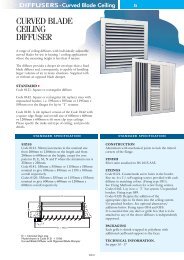
GRILLES-<strong>Linear</strong> <strong>Bar</strong><br />
LINEAR BAR<br />
GRILLES<br />
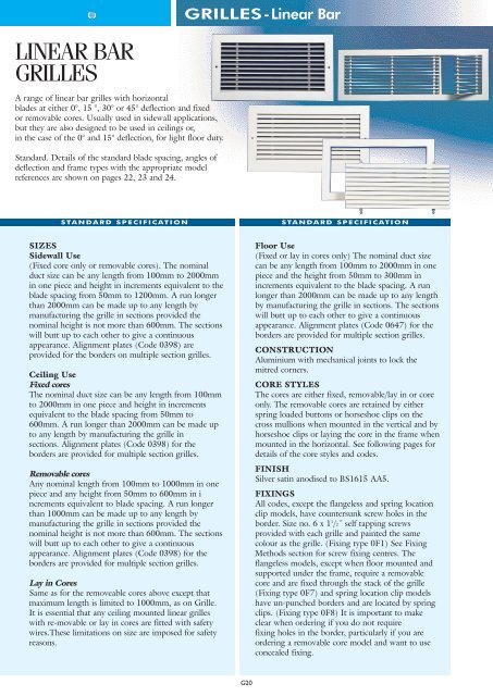
A range of linear bar grilles with horizontal<br />
blades at either 0°, 15 °, 30° or 45° deflection and fixed<br />
or removable cores. Usually used in sidewall applications,<br />
but they are also designed to be used in ceilings or,<br />
in the case of the 0° and 15° deflection, for light floor duty.<br />
Standard. Details of the standard blade spacing, angles of<br />
deflection and frame types with the appropriate model<br />
references are shown on pages 22, 23 and 24.<br />
STANDARD SPECIFICATION<br />
STANDARD SPECIFICATION<br />
SIZES<br />
Sidewall Use<br />
(Fixed core only or removable cores). The nominal<br />
duct size can be any length from 100mm to 2000mm<br />
in one piece and height in increments equivalent to the<br />
blade spacing from 50mm to 1200mm. A run longer<br />
than 2000mm can be made up to any length by<br />
manufacturing the grille in sections provided the<br />
nominal height is not more than 600mm. The sections<br />
will butt up to each other to give a continuous<br />
appearance. Alignment plates (Code 0398) are<br />
provided for the borders on multiple section grilles.<br />
Ceiling Use<br />
Fixed cores<br />
The nominal duct size can be any length from 100mm<br />
to 2000mm in one piece and height in increments<br />
equivalent to the blade spacing from 50mm to<br />
600mm. A run longer than 2000mm can be made up<br />
to any length by manufacturing the grille in<br />
sections. Alignment plates (Code 0398) for the<br />
borders are provided for multiple section grilles.<br />
Removable cores<br />
Any nominal length from 100mm to 1000mm in one<br />
piece and any height from 50mm to 600mm in i<br />
ncrements equivalent to blade spacing. A run longer<br />
than 1000mm can be made up to any length by<br />
manufacturing the grille in sections provided the<br />
nominal height is not more than 600mm. The sections<br />
will butt up to each other to give a continuous<br />
appearance. Alignment plates (Code 0398) for the<br />
borders are provided for multiple section grilles.<br />
Lay in Cores<br />
Same as for the removeable cores above except that<br />
maximum length is limited to 1000mm, as on Grille.<br />
It is essential that any ceiling mounted linear grilles<br />
with re-movable or lay in cores are fitted with safety<br />
wires.These limitations on size are imposed for safety<br />
reasons.<br />
Floor Use<br />
(Fixed or lay in cores only) The nominal duct size<br />
can be any length from 100mm to 2000mm in one<br />
piece and the height from 50mm to 300mm in<br />
increments equivalent to the blade spacing. A run<br />
longer than 2000mm can be made up to any length<br />
by manufacturing the grille in sections. The sections<br />
will butt up to each other to give a continuous<br />
appearance. Alignment plates (Code 0647) for the<br />
borders are provided for multiple section grilles.<br />
CONSTRUCTION<br />
Aluminium with mechanical joints to lock the<br />
mitred corners.<br />
CORE STYLES<br />
The cores are either fixed, removable/lay in or core<br />
only. The removable cores are retained by either<br />
spring loaded buttons or horseshoe clips on the<br />
cross mullions when mounted in the vertical and by<br />
horseshoe clips or laying the core in the frame when<br />
mounted in the horizontal. See following pages for<br />
details of the core styles and codes.<br />
FINISH<br />
Silver satin anodised to BS1615 AA5.<br />
FIXINGS<br />
All codes, except the flangeless and spring location<br />
clip models, have countersunk screw holes in the<br />
border. Size no. 6 x 1 1 /2˝ self tapping screws<br />
provided with each grille and painted the same<br />
colour as the grille. (Fixing type 0F1) See Fixing<br />
Methods section for screw fixing centres. The<br />
flangeless models, except when floor mounted and<br />
supported under the frame, require a removable<br />
core and are fixed through the stack of the grille<br />
(Fixing type 0F7) and spring location clip models<br />
have un-punched borders and are located by spring<br />
clips. (Fixing type 0F8) It is important to make<br />
clear when ordering if you do not require<br />
fixing holes in the border, particularly if you are<br />
ordering a removable core model and want to use<br />
concealed fixing.<br />
G20
GRILLES-<strong>Linear</strong> <strong>Bar</strong><br />
OPTIONAL ALTERNATIVES/ADDITIONS<br />
PAN ADAPTORS, PLENUM & HEADER BOXES<br />
PACKAGING<br />
Each grille is individually shrink wrapped in<br />
polythene with additional cardboard support to the<br />
faces. Alignment plates are attached to one section<br />
in a linen draw-string bag.<br />
TECHNICAL INFORMATION<br />
See page 28<br />
SIZES<br />
Non standard sizes. We are not able to manufacture<br />
sizes other than those shown under the standard<br />
specification.<br />
DAMPERS<br />
Opposed blade damper. A clip on opposed blade<br />
damper (Code 0106) can be fitted, provided the<br />
nominal height does not exceed 450mm. The<br />
exceptions are all the fixed core linear grilles that<br />
have a blade pitch of 6.25mm and the 45° deflection<br />
with a blade pitch of 12.5mm because it is not<br />
possible to access the damper operator on these<br />
particular models, unless the core is removable.<br />
Dampers cannot be fitted to ceiling mounted lay in<br />
models either.<br />
FINISHES<br />
Any BS, RAL or NCS colour. Code 0145. Please<br />
specify the colour reference. We suggest powder<br />
coating on top of anodising for swimming pool<br />
applications. It may also be possible to anodise to<br />
alternative finishes for substantial quantities.<br />
Details on request.<br />
FIXINGS<br />
Concealed fixings / sub-frames are available. (Fixing<br />
type OF3) See Fixing Methods section. Please make<br />
sure that if you are fixing the grille by concealed<br />
methods, you order the grille with un-punched<br />
borders. The 0 in the product code becomes 9.<br />
MITRED CORNERS<br />
Angled mitred corners. Any angled corner section can<br />
be manufactured from 40° to 179°. See page G27 for<br />
Codes and details.<br />
2 WAY DISCHARGE<br />
Two way blow. Most of the 15°, 30° and 45°<br />
models can be made as two way opposite blow with<br />
the blades parallel to the long dimension. The first<br />
figure in the code would be 9 not 0. Please contact<br />
Head Office for details.<br />
SAFETY WIRES<br />
Safety wires (Code 0379) can be provided to attach<br />
the core to the border, where the core is removable,<br />
in order to minimise the possibility of accidents.<br />
They are fitted as standard on ceiling mounted<br />
removable core models.<br />
(Un-insulated)<br />
Top entry pan adaptor without flange (120mm high)*. Code 0323.<br />
Top entry pan adaptor without flange (17mm high). Code 0338.<br />
This height of pan adaptor should only be used where the spigot<br />
diameter plus 50mm is equal to or greater than the largest nominal<br />
dimension of the pan and the grille does not have a damper fitted<br />
to it.<br />
Top entry pan adaptor with flange*. Code 0328.<br />
Side entry plenum flange for use on single grilles up to and<br />
including 2 metres in length*. Code 0335.<br />
Side entry plenum with flange for use on single grilles up to and<br />
including 2 metres in length*. Code 0324.<br />
Side entry header box without flange for use on continuous runs<br />
over 2 metres long without opposed blade dampers. Code 0350.<br />
Side entry header box without flange for use on continuous runs<br />
over 2 metres long with opposed blade dampers. Code 0362.<br />
Side entry header box with flange for use on continuous runs over<br />
2 metres long without opposed blade dampers.Code 0363.<br />
Top entry header box with flange and flush fitting end caps<br />
for use on continuous runs over 2 metres long without dampers.<br />
Code 0374.<br />
Top entry header box with flange and flush fitting end caps for use<br />
on continuous runs over 2 metres long with dampers. Code 0364.<br />
Items with an * can be used on grilles with or without an opposed<br />
blade damper.<br />
Please see Sheet MetalWork section for details and codes for top<br />
entry plenum and header boxes, additional spigots and insulation<br />
for plenums and header boxes that are available.<br />
Pan adaptors, plenum boxes and header boxes can be fitted with<br />
quadrant dampers for either manual (Code 0483) or cord operated<br />
(Code 0484) control.<br />
We can also design boxes with non standard heights where there is<br />
limited space above the ceiling or in the cavity.<br />
ORDERING DETAILS<br />
• The code for the basic product should have at least<br />
13 digits. See page 1.<br />
• Please always give the length first then the height.<br />
• Add Codes for additions / alternatives as suffixes.<br />
• Please make sure you order un-punched borders if you<br />
order concealed fixings.<br />
EXAMPLE:<br />
A linear grille to fit an opening 2300mm long x<br />
200mm high having 15° deflection blades, a removable<br />
core retained by horse-shoe clips, opposed blade<br />
damper, pan adaptor without flange, to be concealed fix<br />
through the stack of the grille and painted<br />
RAL 9010 satin would be coded:-<br />
0237/02300/0200+0106+0323+0145-RAL 9010<br />
satin, + OF2.<br />
(un-punched borders).<br />
Applications. Supply * Extract * Sidewall * Ceiling *<br />
Floor * Transfer *<br />
G21
GRILLES-<strong>Linear</strong> <strong>Bar</strong><br />
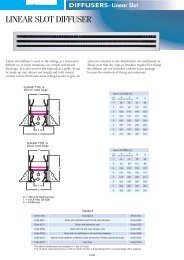
3.3mm Blades with 0° Deflection<br />
18.75<br />
18.75mm Centres.<br />
FLANGED.<br />
Code 0221 Fixed Core.<br />
Code 0384 Fixed Core. Spring Location Clips.<br />
Code 0402 Core Only.<br />
Code 0228 Removable Core Spring. Spring button.<br />
Code 0235 Removable Core Spring. Spring Clip.<br />
Code 0242 Removable Core, Lay-in.<br />
30mm clearance required above core.<br />
Code 0512 Floor Frame Fixed Core.*<br />
Code 0516 Floor Frame with lay-in Core.*<br />
RECESSED.<br />
Code 0452 Fixed Core.* + Sidewall or Ceiling<br />
Code 0453 Lay-in Core.* Floor<br />
Code 0624 Removable core. Spring Button.<br />
Code 0674 Fixed Core Floor.* +<br />
* Need to be supported under frame when used in the floor.<br />
+ Fixing only through the back of the stack or with duct straps.<br />
FREE AREA APPROXIMATELY 70% OF DUCT CONNECTION<br />
Sidewall<br />
Suggested Uses<br />
Ceiling<br />
Light<br />
Floor<br />
Convector<br />
Casings<br />
Can OBD<br />
be Fitted<br />
Safety Wires<br />
required if<br />
fitted in<br />
ceiling<br />
3 3 3 3<br />
3 3<br />
3<br />
3 3 3 3 3<br />
3 3 3 3 3<br />
3 3 3<br />
3 3<br />
3 3<br />
3 3 3 3<br />
3 3 3<br />
3 3 3 3 3<br />
3 3<br />
6.25<br />
6.25mm Centres.<br />
FLANGED.<br />
Code 0222 Fixed Core.<br />
Code 0382 Fixed Core. Spring Location Clips.<br />
Code 0400 Core Only.<br />
Code 0229 Removable Core Spring. Spring button.<br />
Code 0236 Removable Core Spring. Spring Clip.<br />
Code 0243 Removable Core, Lay-in Removable Core.<br />
30mm clearance required above core.<br />
Code 0510 Floor Frame Fixed Core.*<br />
Code 0514 Floor Frame with lay-in Core.*<br />
RECESSED.<br />
Code 0450 Fixed Core.*+ Sidewall & Ceiling<br />
Code 0451 Lay-in Core. Floor<br />
Code 0623 Removable core. Spring Button.<br />
Code 0675 Fixed Core Floor.* +<br />
* Need to be supported under frame.<br />
+ Fixing only through the back of the stack or with duct straps.<br />
FREE AREA APPROXIMATELY 42% OF DUCT CONNECTION<br />
Sidewall<br />
Suggested Uses<br />
Ceiling<br />
Light<br />
Floor<br />
Convector<br />
Casings<br />
Can OBD<br />
be Fitted<br />
Safety Wires<br />
required if<br />
fitted in<br />
ceiling<br />
3 3 3<br />
3<br />
3<br />
3 3 3 3 3<br />
3 3 3 3 3<br />
3 3 3<br />
3<br />
3 3<br />
3 3 3<br />
3 3 3<br />
3 3 3 3<br />
3<br />
12.5<br />
12.5mm Centres.<br />
FLANGED.<br />
Code 0217 Fixed Core.<br />
Code 0383 Fixed Core. Spring Location Clips.<br />
Code 0401 Core Only.<br />
Code 0225 Removable Core Spring. Spring button.<br />
Code 0232 Removable Core Spring. Spring Clip.<br />
Code 0238 Removable Core, Lay-in Removable Core.<br />
30mm clearance required above core.<br />
Code 0511 Floor Frame Fixed Core.*<br />
Code 0515 Floor Frame with lay-in Core.*<br />
RECESSED.<br />
Code 0462 Fixed Core.*+ Sidewall & Ceiling<br />
Code 0463 Lay-in Core. Floor<br />
Code 0622 Removable core. Spring Button.<br />
Code 0676 Fixed Core Floor.* +<br />
* Need to be supported under frame.<br />
+ Fixing only through the back of the stack or with duct straps.<br />
FREE AREA APPROXIMATELY 61% OF DUCT CONNECTION<br />
Sidewall<br />
Suggested Uses<br />
Ceiling<br />
Light<br />
Floor<br />
Convector<br />
Casings<br />
Can OBD<br />
be Fitted<br />
Safety Wires<br />
required if<br />
fitted in<br />
ceiling<br />
3 3 3 3<br />
3 3<br />
3<br />
3 3 3 3 3<br />
3 3 3 3 3<br />
3 3 3<br />
3 3<br />
3 3<br />
3 3 3 3<br />
3 3 3<br />
3 3 3 3<br />
3 3<br />
G22
GRILLES-<strong>Linear</strong> <strong>Bar</strong><br />
3.3mm Blades with 15° Deflection<br />
15°<br />
12.5<br />
12.5mm Centres.<br />
FLANGED.<br />
Code 0230 Fixed Core.<br />
Code 0391 Fixed Core. Spring Location Clips.<br />
Code 0405 Core Only.<br />
Code 0231 Removable Core. Spring Button.<br />
Code 0237 Removable Core. Spring Clip.<br />
Code 0244 Removable Core. Lay-in.<br />
30mm clearance required above core.<br />
Code 0513 Floor Frame Fixed Core.*<br />
Code 0517 Floor Frame Lay-in Core.*<br />
RECESSED<br />
Code 0458 Fixed Core.*+<br />
Code 0459 Lay-in Core<br />
Code 0625 Removable Core. Spring Button<br />
Code 0678 Fixed Core Floor.* +<br />
* Need to be supported under frame.<br />
+ Fixing only through the back of the stack or with duct straps.<br />
FREE AREA APPROXIMATELY 62% OF DUCT CONNECTION<br />
Sidewall<br />
Suggested Uses<br />
Ceiling<br />
Light<br />
Floor<br />
Convector<br />
Casings<br />
Can OBD<br />
be Fitted<br />
Safety Wires<br />
required if<br />
fitted in<br />
ceiling<br />
3 3 3 3<br />
3 3<br />
3<br />
3 3 3 3 3<br />
3 3 3 3 3<br />
3 3 3<br />
3 3<br />
3 3<br />
3 3 3 3<br />
3 3<br />
3 3 3 3<br />
3 3<br />
3.3mm Blades with 30° Deflection<br />
30°<br />
12.5<br />
12.5mm Centres.<br />
FLANGED.<br />
Code 0251 Fixed Core.<br />
Code 0392 Fixed Core. Spring Location Clips<br />
Code 0406 Core Only.<br />
Code 0253 Removable Core. Spring Button.<br />
Code 0252 Removable Core. Spring Clip.<br />
Code 0254 Removable Core Lay-in.<br />
30mm clearance required above core.<br />
RECESSED<br />
Code 0671 Fixed Core.*+<br />
Code 0626 Removable Core. Spring Button<br />
+ Fixing only through the back of the stack or with duct straps.<br />
FREE AREA APPROXIMATELY 60% OF DUCT CONNECTION<br />
Sidewall<br />
Suggested Uses<br />
Ceiling<br />
Light<br />
Floor<br />
Convector<br />
Casings<br />
Can OBD<br />
be Fitted<br />
Safety Wires<br />
required if<br />
fitted in<br />
ceiling<br />
3 3 3 3<br />
3 3<br />
3<br />
3 3 3 3 3<br />
3 3 3 3 3<br />
3 3 3<br />
3<br />
3 3 3 3<br />
3 3 3 3 3<br />
3.3mm Blades with 45° Deflection<br />
45°<br />
12.5<br />
12.5mm Centres.<br />
FLANGED.<br />
Code 0218 Fixed Core.<br />
Code 0385 Fixed Core. Spring Location Clips.<br />
Code 0403 Core Only.<br />
Code 0226 Removable Core. Spring Button.<br />
Code 0233 Removable Cor.e Spring Clip.<br />
Code 0239 Removable Core. Lay-in.<br />
30mm Clearance Required Above Core.<br />
RECESSED<br />
Code 0627 Removable Cor.e Spring Button.<br />
Code 0670 Fixed Core.*+<br />
* Need to be supported under frame.<br />
+ Fixing only through the back of the stack or with duct straps.<br />
FREE AREA APPROXIMATELY 59% OF DUCT CONNECTION<br />
Sidewall<br />
Suggested Uses<br />
Ceiling<br />
Light<br />
Floor<br />
Convector<br />
Casings<br />
Can OBD<br />
be Fitted<br />
Safety Wires<br />
required if<br />
fitted in<br />
ceiling<br />
3 3 3<br />
3<br />
3<br />
3 3 3 3 3<br />
3 3 3 3 3<br />
3 3 3<br />
3 3 3<br />
3<br />
G23
GRILLES-<strong>Linear</strong> <strong>Bar</strong><br />
3.3mm Blades with 45° Deflection<br />
45°<br />
18.75<br />
18.75mm Centres.<br />
Flanged.<br />
Code 0219 Fixed Core.<br />
Code 0390 Fixed Core. Spring Location Clips.<br />
Code 0404 Core Only.<br />
Code 0227 Re-movable Core. Spring Button.<br />
Code 0234 Re-movable Core. Spring Clip.<br />
Code 0240 Re-movable Core. Lay-in.<br />
30mm Clearance Required Above Core.<br />
RECESSED<br />
Code 0672 Fixed Core.*+<br />
Code 0673 Re-movable Core. Spring Button.<br />
* Need to be supported under frame.<br />
+ Fixing only through back of the stack or with duct straps.<br />
FREE AREA APPROXIMATELY 67% OF DUCT CONNECTION<br />
Sidewall<br />
Suggested Uses<br />
Ceiling<br />
Light<br />
Floor<br />
Convector<br />
Casings<br />
Can OBD<br />
be Fitted<br />
Safety Wires<br />
required if<br />
fitted in<br />
ceiling<br />
3 3 3 3<br />
3 3<br />
3<br />
3 3 3 3 3<br />
3 3 3 3 3<br />
3 3 3<br />
3 3 3 3<br />
3 3<br />
3 3 3 3 3<br />
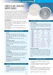
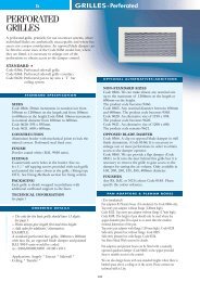
Model shown is Code 0511 + 0106<br />
0° <strong>Linear</strong> Grille in a Flanged Floor Frame, fitted with Damper<br />
If Lay-in Core is Required, Code becomes 0515 +0106<br />
23.5<br />
Overall = D + 35mm<br />
4<br />
20.5<br />
36<br />
78<br />
15 Max Clearance<br />
Over Stack = D - 2mm<br />
Opening Size = D<br />
For grille lengths less than and including 2m.<br />
The frame would be made in one section as below.<br />
2000mm Max.<br />
300mm Max Centres<br />
For grille runs greater than 2m but less than 4m,<br />
grille would be made in 2 equal sections as below<br />
Equal<br />
Equal<br />
For grille runs greater than 4m the length is divided<br />
The nearest number of equal sections below 2m long.<br />
Equal Equal Equal<br />
No end border fitted when<br />
part of a continuous run<br />
Mullions fitted inside<br />
2m Max Length in 1 Section<br />
G24
GRILLES-<strong>Linear</strong> <strong>Bar</strong><br />
25<br />
2.5<br />
D + 35mm<br />
12.5<br />
11.5<br />
6<br />
1.5<br />
12.5<br />
23.7<br />
3.5<br />
22.5<br />
67<br />
D + 35mm<br />
D<br />
23.5<br />
68<br />
D = Nominal Duct size<br />
Model shown is Code 0217 + 0106<br />
<strong>Linear</strong> <strong>Bar</strong> Grille with fixed core, blades with<br />
0° deflection on 12.5mm centres and fitted<br />
with Opposed Blade Damper<br />
D = Nominal Duct size<br />
Model shown is Code 0225 + 0106<br />
<strong>Linear</strong> <strong>Bar</strong> Grille with 0° deflection blades on<br />
12.5mm centres. Removable core retained by<br />
Button Fasteners and fitted with Opposed Blade Damper<br />
23.5<br />
68<br />
D<br />
D - 2mm<br />
30mm Min. Clearance<br />
For Core Removal<br />
22.5<br />
23.7<br />
12.5<br />
D + 43mm<br />
27.7<br />
12.5<br />
D + 35mm<br />
D<br />
D = Nominal Duct size<br />
Model shown is Code 0238<br />
<strong>Linear</strong> <strong>Bar</strong> Grille with 0° deflection blades<br />
On 12.5mm centres with Lay-in removable core<br />
D<br />
D + 0.5mm<br />
Pitch<br />
2.7<br />
X<br />
19.5<br />
D = Nominal Duct size<br />
Model shown is Code 0232 + 0106<br />
<strong>Linear</strong> <strong>Bar</strong> Grille with 0° deflection blades on<br />
12.5mm centres. Removable core retained by<br />
Horseshoe Spring Clips. Fitted with Opposed<br />
Blade Damper<br />
Code 0401 core only <strong>Linear</strong> <strong>Bar</strong> Grille 0° deflection blades on<br />
12.5mm Centres<br />
Standard sizes for the D dimension should be in 12.5mm increments<br />
Some intermediate aizes can be made by adjusting dimension X<br />
Contact Head Office for details<br />
D + 35mm<br />
100 Min.<br />
4.5<br />
23.5<br />
D + 10mm<br />
D = Nominal Duct size<br />
<strong>Linear</strong> Grille with access door<br />
Suffix Code 0248 on <strong>Linear</strong> Model<br />
G25
GRILLES-<strong>Linear</strong> <strong>Bar</strong><br />
D = Nominal Duct size<br />
Model shown is Code 0462 +01060<br />
<strong>Linear</strong> <strong>Bar</strong> Grille 0° deflection blades on 12.5mm centres with fixed<br />
core<br />
In a Recessed Flangeless Frame with Opposed Blade Damper.<br />
NOTE - the core can be Lay-in if the floor code becomes 0463<br />
5<br />
D<br />
D - 2mm<br />
12.5<br />
24.5<br />
40<br />
82<br />
15<br />
15<br />
For grille lengths less than and including 2m.<br />
The frame would be made in one section as below.<br />
2000mm Max.<br />
For grille runs greater than 2m but less than 4m,<br />
<strong>Grilles</strong> would be made In 2 equal sections as below<br />
Equal<br />
Equal<br />
For grille runs greater than 4m the length is divided into<br />
The nearest number of equal sections below 2m long.<br />
Equal Equal Equal<br />
Mullions fitted inside<br />
No end<br />
border<br />
fitted<br />
when<br />
part of a<br />
continuous<br />
run<br />
300mm Max Centres<br />
2m Max Length in 1 Section<br />
40<br />
81.5<br />
1 5<br />
5<br />
2.5<br />
D + 35mm<br />
12.5<br />
25<br />
22.5<br />
67<br />
12.5<br />
D - 2mm<br />
D<br />
D<br />
D = Nominal Duct size<br />
Model shown is Code 0383 + 0106<br />
<strong>Linear</strong> <strong>Bar</strong> Grille With 0° deflection blade on 12.5mm<br />
centres with fixed core, located in a horizontal surface by<br />
Spring Location Clips. Fitted with an Opposed Blade<br />
Damper. (Unpunched borders as standard)<br />
Not to be used in ceiling or vertical surfaces<br />
D = Nominal Duct size<br />
Model shown is Code 0622 +0106<br />
Recessed Frame <strong>Linear</strong> <strong>Bar</strong> Grille 0° deflection blades on<br />
12.5mm centres<br />
Removable core retained by Button Fasteners and fitted<br />
with Opposed Blade Damper<br />
Caution: Fixing this type of frame with a fixed core is not<br />
possible.<br />
G26
GRILLES-<strong>Linear</strong> <strong>Bar</strong><br />
<strong>Linear</strong> Grille Mitred Corner<br />
Code 0464 0° deflection blades on 6.25mm centres<br />
Code 0465 0° deflection blades on 12.50mm centres<br />
Code 0466 0° deflection blades on 18.75mm centres<br />
Code 0467 45° deflection blades on 12.50mm centres<br />
Code 0468 45° deflection blades on 18.75mm centres<br />
Code 0469 15° deflection blades on 12.50mm centres<br />
Code 0470 30° deflection blades on 12.50mm centres<br />
90°<br />
300 Inside<br />
Opening = Nominal Grille Height + 317.5mm<br />
300 Inside<br />
Opening = Nominal Grille Height + 317.5mm<br />
Use Formula<br />
Nom Opening<br />
Use Formula<br />
300 Inside<br />
300 Inside<br />
Nom Opening<br />
To Calculate The Outside Length For Any Angle Other Than 90°, Use The Formula Below<br />
First Calculate The Angle Of The Cut = (180 - ) divided by 2<br />
Then The Outside Opening Length = [ (Nominal Opening + 17.5mm) x Tan of The Angle Of Cut ] + 300mm<br />
e.g. Assume Nominal Dimension = 300mm and = 135° then angle of cut = (180 - 135) / 2 = 22.5°<br />
Outside Opening Length = [ (300 + 17.5mm) x Tan 22.5° ] + 300 = 431.5mm<br />
G27
GRILLES-<strong>Linear</strong> <strong>Bar</strong><br />
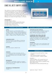
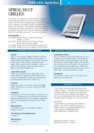
PERFORMANCE DATA FOR<br />
LINEAR GRILLES<br />
• This nomogram is based on Code 217 <strong>Linear</strong><br />
<strong>Grilles</strong> and corrections should be applied for other<br />
codes. In the case of <strong>Linear</strong> grilles, the fixed parameters<br />
for selection are usually volume, throw and/or<br />
width of grille. To select for the volume and throw, the<br />
volume should be related to a metre run. For example,<br />
if the length is to be 500mm and the volume 0.15m 3 /s,<br />
then volume per metre would be 1 ÷ 0.5 x 0.15 =<br />
0.3m 3 /s/. If the required throw is 7 metres, place a<br />
ruler on the volume line at 0.3 and cross the throw<br />
line at 7 metres. The rule crosses the width line at<br />
275mm. If there is a limitation on the width of the<br />
grille, say 200mm wide in the above case, and the<br />
throw was critical, then the length would have to be<br />
increased. Design throws should always be corrected<br />
using tables 1, 2, 3 and 4 as appropriate, before<br />
entering the nomogram. Pressure drop and NR<br />
should be corrected after using the nomogram.<br />
PERFORMANCE DATA<br />
TABLE 1<br />
Corrections for<br />
other <strong>Grilles</strong><br />
Data given is for isothermal conditions and for free space application.<br />
No opposed blade damper. For dampers add 40% to the pressure drop and 5NR.<br />
Grille<br />
Type<br />
116<br />
117<br />
118<br />
119<br />
Pressure<br />
Correction Factors<br />
x 1.1<br />
x 1.0<br />
x 1.2<br />
x 1.4<br />
Sound<br />
Factors<br />
÷3<br />
x 1<br />
÷ 4<br />
÷ 10<br />
Throw<br />
Factors<br />
x 1<br />
x 1<br />
÷ 0.95<br />
÷ 0.95<br />
Volume (Q)<br />
m 3 /s/ metre run<br />
2.0<br />
Nominal Grille<br />
Width mm x 1000mm long<br />
222<br />
229<br />
236<br />
243<br />
217<br />
225<br />
232<br />
238<br />
221<br />
228<br />
235<br />
242<br />
230<br />
231<br />
237<br />
244<br />
251<br />
253<br />
252<br />
254<br />
218<br />
226<br />
233<br />
239<br />
219<br />
227<br />
234<br />
240<br />
x 1.2<br />
x 1.2<br />
x 1.2<br />
x 1.2<br />
x 1.0<br />
x 1.0<br />
x 1.0<br />
x 1.0<br />
x 0.8<br />
x 0.8<br />
x 0.8<br />
x 0.8<br />
x 1.1<br />
x 1.1<br />
x 1.1<br />
x 1.1<br />
x 1.2<br />
x 1.2<br />
x 1.2<br />
x 1.2<br />
x 1.3<br />
x 1.3<br />
x 1.3<br />
x 1.3<br />
x 1.2<br />
x 1.2<br />
x 1.2<br />
x 1.2<br />
÷ 4<br />
÷4<br />
÷4<br />
÷ 4<br />
x 1<br />
x 1<br />
x 1<br />
x 1<br />
÷4<br />
÷ 4<br />
÷4<br />
÷4<br />
÷3<br />
÷3<br />
÷ 3<br />
÷3<br />
÷10<br />
÷10<br />
÷10<br />
÷ 10<br />
÷15<br />
÷15<br />
÷15<br />
÷15<br />
÷10<br />
÷10<br />
÷10<br />
÷ 10<br />
÷ 0.95<br />
÷ 0.95<br />
÷ 0.95<br />
÷ 0.95<br />
x 1<br />
x 1<br />
x 1<br />
x 1<br />
÷ 0.95<br />
÷ 0.95<br />
÷ 0.95<br />
÷ 0.95<br />
÷ 0.95<br />
÷ 0.95<br />
÷ 0.95<br />
÷ 0.95<br />
÷ 0.82<br />
÷ 0.82<br />
÷ 0.82<br />
÷ 0.82<br />
÷ 0.70<br />
÷ 0.70<br />
÷ 0.70<br />
÷ 0.70<br />
÷ 0.70<br />
÷ 0.70<br />
÷ 0.70<br />
÷ 0.70<br />
1.5<br />
1.0<br />
0.9<br />
0.8<br />
0.7<br />
0.6<br />
0.5<br />
0.4<br />
0.3<br />
0.2<br />
0.15<br />
20<br />
10<br />
8<br />
7<br />
6<br />
5<br />
4<br />
3<br />
2<br />
Pressure drop<br />
(∆Pt ) Pa<br />
60<br />
50<br />
40<br />
30<br />
20<br />
NRLW<br />
50<br />
40<br />
30<br />
20<br />
10<br />
6.0<br />
5.0<br />
4.0<br />
3.0<br />
2.5<br />
2.0<br />
1.5<br />
1.0<br />
Duct<br />
velocity<br />
m/s<br />
100<br />
150<br />
200<br />
250<br />
300<br />
350<br />
400<br />
450<br />
500<br />
550<br />
600<br />
TABLE 2<br />
Corrections to throw<br />
due to ceiling.<br />
Grille more than<br />
600mm from ceiling<br />
Grille more than<br />
600mm from ceiling<br />
0<br />
0<br />
TABLE 3<br />
Throw corrections<br />
for length<br />
Grille Length (m) Factor<br />
0.66 - 1.00 -<br />
1.66 - 2.00 +1.1<br />
› 2.01 +1.2<br />
0.1<br />
0.09<br />
0.08<br />
0.07<br />
0.06<br />
0.05<br />
1<br />
Throw in metres.<br />
Terminal Velocity<br />
(Vt) 0.25m/s<br />
0.04<br />
TABLE 4<br />
Throw corrections<br />
for other (V t )<br />
TABLE 5<br />
Sound corrections<br />
for length<br />
0.03<br />
Terminal Velocity Factor<br />
0.25 m/s + 1.0<br />
0.375 m/s +0.67<br />
0.5 m/s +0.5<br />
Grille Length (m) Factor<br />
0.33 - 1.00 -<br />
1.01 - 1.66 +1 NR<br />
1.67 - 2.00 +2 NR<br />
2.30 - 3.00 +3 NR<br />
0.02<br />
G28