A4 Diffuser - Linear Slot.qxd - Scottaire
A4 Diffuser - Linear Slot.qxd - Scottaire
A4 Diffuser - Linear Slot.qxd - Scottaire
- No tags were found...

Create successful ePaper yourself
Turn your PDF publications into a flip-book with our unique Google optimized e-Paper software.
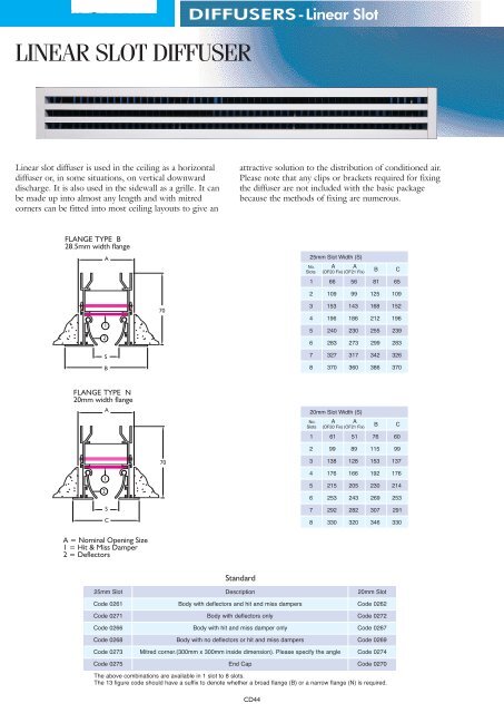
LINEAR SLOT DIFFUSERDIFFUSERS-<strong>Linear</strong> <strong>Slot</strong><strong>Linear</strong> slot diffuser is used in the ceiling as a horizontaldiffuser or, in some situations, on vertical downwarddischarge. It is also used in the sidewall as a grille. It canbe made up into almost any length and with mitredcorners can be fitted into most ceiling layouts to give anattractive solution to the distribution of conditioned air.Please note that any clips or brackets required for fixingthe diffuser are not included with the basic packagebecause the methods of fixing are numerous.FLANGE TYPE B28.5mm width flangeA7012SBFLANGE TYPE N20mm width flangeA7012SCA = Nominal Opening Size1 = Hit & Miss Damper2 = Deflectors25mm <strong>Slot</strong>StandardDescription20mm <strong>Slot</strong>Code 0261 Body with deflectors and hit and miss dampersCode 0262Code 0271 Body with deflectors onlyCode 0272Code 0266 Body with hit and miss damper onlyCode 0267Code 0268 Body with no deflectors or hit and miss dampersCode 0269Code 0273 Mitred corner.(300mm x 300mm inside dimension). Please specify the angle Code 0274Code 0275 End CapCode 0270The above combinations are available in 1 slot to 8 slots.The 13 figure code should have a suffix to denote whether a broad flange (B) or a narrow flange (N) is required.CD44
DIFFUSERS-<strong>Linear</strong> <strong>Slot</strong>STANDARD SPECIFICATIONOPTIONAL ALTERNATIVES/ADDITIONS25mm20mmSIZESThe length can be any nominal size from 300mm to2000mm in one piece. A run longer than 2 metres canbe made up to any nominal length from multiplesections butted up together to give a continuousappearance. Splice plates are provided to align sectionsin a multiple run. The nominal width is determined bythe number and width of the slots and the type offixing to be used. The table below shows thisrelationship.<strong>Slot</strong> <strong>Diffuser</strong> Nominal Width (Opening Size)<strong>Slot</strong> WidthFixing Type OF20Fixing Type OF21Fixing Type OF20Fixing Type OF21Number Of <strong>Slot</strong>s1 2 3 4 5 6 7 866 109 153 196 240 283 327 37056 99 143 186 230 273 317 36061 99 138 176 215 253 292 33051 89 128 166 205 243 282 320CONSTRUCTIONAluminium body and deflector blades with Zinteccoated sheet steel hit and miss dampers. Un-punchedborders. The deflector blades are made in one lengthand the hit and miss dampers in one length. Availablewith broad (B) or narrow flange (N).FINISHBody silver satin anodised to BS 1615 AA5. Deflectorblades black anodised. Hit and miss dampers powdercoated RAL 9005 matt (black).FIXINGSThe basic diffuser has un-punched borders and doesnot include any fixing clips or brackets except forinternal (Code 0309) and external (Code 0310) spliceplates to join multiple section runs together.All other clips or brackets are supplied separately.Details of the various fixing methods are shown onpage47 and details of the clips and brackets for thesefixings are shown in the alternative/additions sectionbelow.PACKAGINGEach length of slot diffuser is packaged in a speciallydesigned cardboard carton with crush resistant ends.Any fixing clips and brackets are packed in a separatecarton to ensure they do not scratch the diffuser intransit. The alignment clips are packed in a linen bagand attached to the diffuser.TECHNICAL INFORMATIONSee pages 51 - 53FINISHESAny BS, RAL or NCS colour. Code 0145.Pleasespecify the colour reference. We suggest powdercoating on top of anodising for swimming poolapplications. It may also be possible to anodise toalternative finishes for substantial quantities.FIXINGSThe borders can be punched with countersunk holes.Size No 6 x 1 1 /2˝ self tapping screws provided andfinished the same colour as the linear slot. (Fixing Type0F1). Please specify hole centres. This method offixing should not be used for sections with plenumboxes or where the material that the slot is being fixedto is not adequate to support the weight. It isadvisable to suspend the equipment from the slababove in these situations. See pages 47 for other fixingmethods for which the following clips or brackets areavailable:-Code 0301. Saddle brackets for Type 0F20, OF26 &OF27 fix.Code 0302. Saddle brackets for Type 0F21 fix.Code 0303. Saddle brackets for Type 0F22 fix.Code 0304. Hanging cleats (wire) for Type 0F23 fix.Code 0305. Hanging cleats (rod) for Type 0F24 fix.Code 0306. Saddle brackets for Type 0F25 fix.The number of saddle brackets required up to 1 metrelong section = 2 off and between 1 metre and 2 metrelong section = 3 off. The number of cleats required upto 1 metre long section = 4 off and between 1 metreand 2 metre long = 6 off.DEFLECTOR BLADE LENGTHThe deflector blades can be made to any length. If itis desirable to herring bone the discharge pattern, toreduce the throw by 15% a length of 300mm to500mm is recommended. The product code prefixwould change to 9 and you need to specify the bladelength required.BLANKING PLATESCode 0395. A blanking plate can be fitted to nonactive sections, if required. These are fabricated fromsheet steel and painted matt black.ADDITIONAL ALIGNMENT PLATESInternal alignment plates. Code 0309.External alignment plates. Code 0310.CEILING TRIM EXTRUSIONSCode 0427. An extrusion to act as a wall plate. Pleasespecify the total length required. See page 47 fordetails as to how it is incorporated into the fixingarrangements.CD45
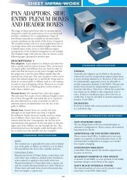
DIFFUSERS-<strong>Linear</strong> <strong>Slot</strong>OPTIONAL ALTERNATIVES/ADDITIONSOPTIONAL ALTERNATIVES/ADDITIONSHEADER BOXESHeader boxes are available manufactured from Zinteccoated sheet steel either un-insulated or insulatedinternally. The internal insulation can be thermal oracoustic/thermal.Code 0316. Un-insulated header box for 1 & 2 slot.0F21Fix.Code 0315. Un-insulated header box for 3 to 8 slot.0F21Fix.Code 0416. Un-insulated header box for 1 & 2 slot.0F20Fix.Code 0415. Un-insulated header box for 3 to 8 slot.0F20Fix.Code 0321. Thermally insulated header box for 1 to 8slot. 0F21Fix.Code 0421. Thermally insulated header box for 1 to 8slot. 0F20Fix.Code 0319. Acoustically insulated (10mm material)header box for 1 to 8 slot. 0F21Fix.Code 0419. Acoustically insulated (10mm material)header box for 1 to 8 slot. 0F20FixCode 0317. Acoustically insulated (25mm material)header box for 1 to 8 slot. 0F21Fix.Code 0417. Acoustically insulated (25mm material)header box for 1 to 8 slot. 0F20Fix.See Sheet Metal Work section for codes, dimensionsand the recommended spigot diameters available forthe different fixing arrangements.We can also design header boxes with non standardheights and spigot combinations where there is limitedspace in the cavity. Contact Head Office for details.Header boxes can be fitted with quadrant dampers inthe spigot for either manual (Code 0483) or cordoperated (Code 0484) control.ORDERING DETAILS• The code for the basic diffuser should have 13 digits.See page 1.• Please always give the length first and then the numberof slots.• Add codes for additions / alternatives as suffixes.EXAMPLE:A 10 metre run of 4 slot (25mm wide slot) with broadflange, deflectors and hit and miss dampers, an end capat each end, body painted RAL9010 satin and with 10off equal size un-insulated header boxes with manuallyoperated quadrant dampers for fixing type 0F21would be coded - 0261/10000/0004B+2x0275+0145(RAL 9010 satin) + 10x 0315/00980/0004.(Spigot size 250mm dia) +0483 +OF21.The saddle brackets would be a separate item.Applications. Supply * Extract * Sidewall * Ceiling *Setting Positions for DeflectorsHorizontal LeftVertical(Horizontal in sidewall application).Horizontal RightBlade against Top ShopBlade Against Bottom StopNote: The blades should be set against the top or bottom stops.CD46
DIFFUSERS-<strong>Linear</strong> <strong>Slot</strong>SLOT DIFFUSER FIXING ARRANGEMENTS FOR USE WITH PLASTER AND T BARCEILINGS AND/OR CEILING TRIM EXTRUSION<strong>Slot</strong> <strong>Diffuser</strong> Fixing Type OF20Concealed bracket mountingSuitable for Plaster Ceiling(<strong>Slot</strong> <strong>Diffuser</strong> suspended from theHeader Box)(Flange Type B only)Suitable for Header Box Codes;0415, 0416, 0417, 0419 & 0421<strong>Slot</strong> <strong>Diffuser</strong> Fixing Type OF21Concealed bracket mountingNot suitable for Plaster Ceiling(<strong>Slot</strong> <strong>Diffuser</strong> suspended from TheHeader Box)(Flange Type B or N)Suitable for Header Box Codes;0315, 0316, 0317, 0319 & 0321<strong>Slot</strong> <strong>Diffuser</strong> Fixing Type OF27Flush to wall with Ceiling Trim Extrusion Code 0427(<strong>Slot</strong> <strong>Diffuser</strong> suspendedfrom the Header Box)(Flange Type B only)Suitable for Header Box Codes;0415, 0416, 0417, 0419, 0421Timber Batten<strong>Slot</strong> <strong>Diffuser</strong> Fixing Type OF23Standard Suspension BracketsTo suit Hanging Wires.(Flange Type B or N)<strong>Slot</strong> <strong>Diffuser</strong> Fixing Type OF24Standard Suspension BracketsTo suit M6 Drop Rods(Flange Type B or N)<strong>Slot</strong> <strong>Diffuser</strong> Fixing Type OF26with Ceiling Trim Extrusion Code 0427(<strong>Slot</strong> <strong>Diffuser</strong> suspendedfrom The Header Box)(Flange Type B only)Suitable for Header Box Codes;0415, 0416, 0417, 0419, 0421<strong>Slot</strong> <strong>Diffuser</strong> Fixing Type OF22Saddle Bracket FixingTo suit Plaster Ceiling(For dummy sections or extractto void) (Flange Type B or N)<strong>Slot</strong> <strong>Diffuser</strong> Fixing Type OF1Screw Fixed through the Flange(Flange Type B only)(Plenum Box’s not to beattached unlessindependently supported<strong>Slot</strong> <strong>Diffuser</strong> Fixing Type OF25with Ceiling Extrusion Code 0427To suit Plaster Ceiling(For dummy sections or extractto void) (Flange Type B or N)Drop Rods and Suspension Wires supplied by othersCD47
DIFFUSERS-<strong>Linear</strong> <strong>Slot</strong>ngNumber55SLOT DIFFUSER MITRED CORNERSCODE 0273 25MM SLOT WIDTH, CODE 0274 20MM SLOT WIDTHOpening X = A + 308mm (Fixing Type OF20) available with Flange B onlyOpening = A + 313mm (Flange B)All Fixings Except OF20å Opening = A + 305mm (Flange N) çXOpening X = A + 308mm (Fixing Type OF20) available with Flange B onlyOpening = A + 313mm (Flange B)All Fixings Except OF20Opening = A + 305mm (Flange N)åXA90°300A300çUse Formula300135°Use Formula300<strong>Slot</strong> <strong>Diffuser</strong> Nominal Opening Dimension ‘A’<strong>Slot</strong> WidthNumber Of <strong>Slot</strong>s1 2 3 4 5 6 7 8Values To Use For X In Formula25mmFixing Type OF20Fixing Type OF2166 109 153 196 240 283 327 37056 99 143 186 230 273 317 360Flange B OF20 FixFlange B OF21 Fix1.3820mmFixing Type OF20Fixing Type OF2161 99 138 176 215 253 292 33051 89 128 166 205 243 282 320Flange N OF20 Fix4.5To calculate the outside opening length for any angle other than 90°, use the formula belowFirst calculate the angle of the cut = (180 - ) divided by 2The outside opening length = [ (Nominal Opening + Xmm) x tan of the angle of cut ] + 300mme.g. Assume 4 x 25mm <strong>Slot</strong> OF20 Fix = 198mm with Flange Type B = 135° then the angle of cut = (180 - 135) / 2 = 22.5°Outside opening length = [ (198 + 13mm) x Tan 22.5° ] + 300 = 387.5mmNote: Mitre sections do not have adjustable deflector blades but are fitted with black blanking plates.CD48
DIFFUSERS-<strong>Linear</strong> <strong>Slot</strong>ASSEMBLY DETAILSSTANDARD LENGTH (2 METRE CUT LENGTH) INSTALLATION2020 Nominal Length2000 Cut Length1980 Header BoxThis example shows a horizontalseam Header Box.1 Header Box2 <strong>Slot</strong> <strong>Diffuser</strong>3 End Cap4 Drop Rods (not included)5 Hanging Brackets6 Spigot for flexible duct connectionTYPICAL RUN ASSEMBLY6000 Nominal1980 Header Box 20 1960 Header Box 201980 Header Box2000 Cut Length 1980 Cut Length2000 Cut LengthRELATIONSHIP BETWEEN NOMINAL, OVERALL & CUT LENGTHSDrawingNumber52Nominal Opening Size = LCut Length = L - 20mm1010Flange Type ‘N’ Overall With End Caps= L + 20mm2020Flange Type ‘B’ Overall With End Caps= L + 36mm2828CD49
DIFFUSERS-<strong>Linear</strong> <strong>Slot</strong>MAKE UP OF RUNSYOUR ORDER SHOULD SHOW THE NOMINAL LENGTH OF THE RUN, I.E. THE OPENING SIZE.The NOMINAL length of a run of <strong>Slot</strong> <strong>Diffuser</strong>s is 20mm longer than the total CUT length. Unless you requestotherwise, we will normally break the run down into cut lengths, as follows:For runs less than and including 2 metresEXAMPLE (Nominal 1600)1580 (Cut length)15801 PieceRuns greater than two metres, but less than and including 4 metres,are made up of two equal pieces.EXAMPLE (Nominal 3800) 3780 (Cut length)18901890Runs of 4 - 6 metres, which are made up of three pieces, the run is madeup of two standard 2 metre lengths, with the odd length in the middle.EXAMPLE (Nominal 5500) 5480 (Cut length)2000 20005480 (Cut length)14802000 14802000WRONG !!RIGHT !!Runs greater than 6 metres are always supplied in an arrangement that ensures visual symmetry. Runs aremade up in multiples of 2 metre cut lengths, with two matching end lengths. To calculate the end lengths,first calculate the number of complete two metre lengths in the run, the divide the remainder by two.EXAMPLE (Nominal 7650) 7630 (Cut length)2000 2000200016307630 (Cut length)1815 200020001815WRONG !!RIGHT !!If the end lengths turn out to be less than one metre long, subtract one two metrelength from the total of two metre lengths, add to the remainder and divide by two.EXAMPLE (Nominal 7300) 7280 (Cut length)640 20002000200064072801640 200020001640WRONG !!RIGHT !!CD50
DIFFUSERS-<strong>Linear</strong> <strong>Slot</strong>PERFORMANCE DATA FOR 25mmSLOT DIFFUSER• The nomogram is based on a metre length of <strong>Slot</strong><strong>Diffuser</strong>. The method in which the nomogram is useddepends on the fixed parameters. These are usuallyvolume and throw. The volume should be related to ametre run. For instance, if the length of slot is to be 2metres and the volume 0.2m 3 /s, the volume per metrewould be 1 ÷ 2 x 0.2 = 0.10m 3 /s. If the design throwis 4 metres @ 0.5m/s (Vt), the design throw should becorrected to allow for the 2 metre length and higherterminal velocity, i.e. 4 ÷ 1.1 ÷0.5 = 7.28. Enter thenomogram with the volume per metre of 0.10 and thethrow of 7.28 metres, and read off 4 slot, NR 20 + 3,Pressure drop 6 Pa. Design throws should always becorrected using Tables 1 and 3 before using thenomogram. Pressure drop and NR should be correctedafter using the nomogram.PERFORMANCE DATATABLE 1Throw Correctionsfor length.Length (m)0.30.51.01.52.03.0Factor÷0.5÷0.7÷1.0÷1.05÷1.1÷1.1Data given for isothermal conditions and ceiling mounted application, supply air,with damper fully open, blades set for left or right discharge.Volume (Q)m 3 /s/m run 2.00.40.3TABLE 2NR Correctionsfor length.Length (m)0.30.51.01.52.03.0+-5-30+2+3+5TABLE 3Correction to Throw forother (V t )TerminalVelocity m/s0.250.3750.50.625Factor+1+0.670.5+0.40.20.150.120.100.090.080.070.060.050.040.03Throw (Lt) in metres.Terminal velocity(Vt) 0.25m/s16141210876434035302520NRLWTotalPressuredrop (∆P t )Pa30201052No. of<strong>Slot</strong>s12345678TABLE 4Correction withoutHeader Box0.02PressureDropNRx0.6 -5Note: The throw can be reduced by 15% using shortdeflection blades and setting them in alternate directions.See optional alternativesCD51
DIFFUSERS-<strong>Linear</strong> <strong>Slot</strong>PERFORMANCE DATA FOR SLOTDIFFUSER in vertical or sidewall application• <strong>Slot</strong> <strong>Diffuser</strong> can be used as a supply or extractdiffuser in either vertical or sidewall application.Where it is used as a sidewall diffuser within 300mmof a ceiling, use the date for discharge within 300mmof a wall.Always correct the design throw before using thenomogram and correct the NR and Pressure drop afterusing the nomogram.CORRECTIONS FOR VERTICAL DISCHARGEFREESPACE DISCHARGE (More than 0.3m from any wallor ceiling in sidewall application)(WITH BLADES FULLY OPEN)Required Throw ÷ 0.35 = Nomogram Throw (Lt)Pressure Drop x 0.8NR - 3RequiredThrowmDISCHARGE WITHIN 0.3M OF WALL (or ceiling in sidewall application)(WITH BLADES FULLY OPEN)Required Throw ÷ 0.5 = Nomogram Throw (Lt)Pressure Drop x 0.8NR - 3RequiredThrowmEFFECT ON VERTICAL THROW OF TEMPERATURE DIFFERENTIAL (T d )No. of<strong>Slot</strong>sTemperature Differential (T d )-15 -10 -5 0 +5 +10 +151 1.541.331.1510.870.750.6522.001.591.2610.790.630.5032.481.881.3710.750.530.414 - 82.711.951.4010.710.510.37For nomogram throw divide design throw by the above factorsCODES 0268 & 0269 ONLY: Corrections for extract applications(WITHOUT BLADES + HIT/MISS)Pressure Drop x 0.64NR - 10Note: All other codes. Use the nomogram data withoutthese corrections in extract applicationsCD53