Download - Carlo Gavazzi
Download - Carlo Gavazzi
Download - Carlo Gavazzi

Create successful ePaper yourself
Turn your PDF publications into a flip-book with our unique Google optimized e-Paper software.
CARLO GAVAZZI<br />
Automation Components<br />
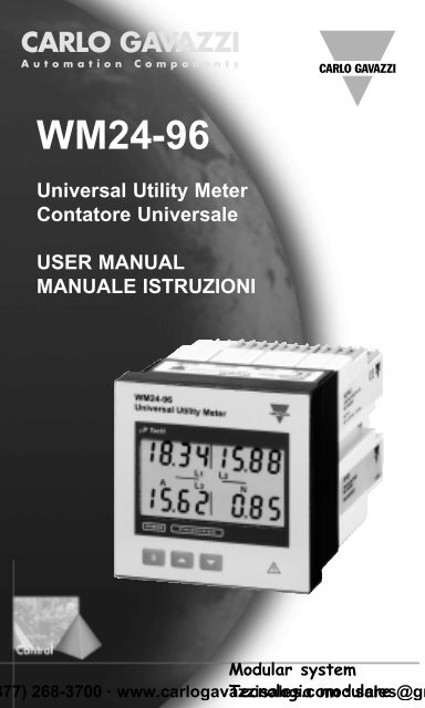
WM24-96<br />
Universal Utility Meter<br />
Contatore Universale<br />
USER MANUAL<br />
MANUALE ISTRUZIONI<br />
Modular system<br />
77) 268-3700 · www.carlogavazzisales.com Tecnologia modulare · sales@gr
CARLO GAVAZZI<br />
Automation Components<br />
WM24-96: Modular Universal Utility<br />
Meter and Power Analyzer<br />
Plug and play module system; energy<br />
meters, gas and water meter.<br />
These are only a few among many<br />
other functions performed by your<br />
WM24-96. What’s more, <strong>Carlo</strong><br />
<strong>Gavazzi</strong> means ISO9001 certification,<br />
a working experience of many<br />
decades and a widespread presence<br />
all over the world. All this because<br />
we want our customers to have the<br />
top service and the top products.<br />
Welcome in the <strong>Carlo</strong> <strong>Gavazzi</strong> world<br />
and compliments for your smart<br />
choice. Visit our website and<br />
evaluate our range of products:<br />
www.carlogavazzi.com<br />
CARLO GAVAZZI<br />
CHOOSING<br />
THANK<br />
FOR<br />
YOU<br />
Plug and Play<br />
Modules<br />
77) 268-3700 · www.carlogavazzisales.com · sales@gr
2 Index<br />
CARLO GAVAZZI<br />
WM24-96, modular universal utility meter and power analyzer<br />
FW rev. 01<br />
TO BEGIN WITH . . . . . . . . . . . . . . . . . . . . . . . . . . . . . .04<br />
■ Front panel description . . . . . . . . . . . . . . . . . . . .04<br />
■ List and description of displayed measuring pages . . . .04<br />
PROGRAMMING . . . . . . . . . . . . . . . . . . . . . . . . . . . . .09<br />
■ Access to the main menu . . . . . . . . . . . . . . . . . . .09<br />
■ Change password . . . . . . . . . . . . . . . . . . . . . . . .09<br />
■ System . . . . . . . . . . . . . . . . . . . . . . . . . . . . . . . .10<br />
■ CT ratio . . . . . . . . . . . . . . . . . . . . . . . . . . . . . . . .10<br />
■ VT ratio . . . . . . . . . . . . . . . . . . . . . . . . . . . . . . . .11<br />
■ Dmd calculation . . . . . . . . . . . . . . . . . . . . . . . . .11<br />
■ Access to the energy meters menus . . . . . . . . . .13<br />
❑ The functions of the Energy Meters submenu. . .13<br />
■ Digital outputs . . . . . . . . . . . . . . . . . . . . . . . . . . .16<br />
❑ Digital output 1 . . . . . . . . . . . . . . . . . . . . . . .16<br />
❑ Pulse digital output . . . . . . . . . . . . . . . . . . . .16<br />
❑ Alarm digital output . . . . . . . . . . . . . . . . . . . .18<br />
❑ Digital output 2 . . . . . . . . . . . . . . . . . . . . . . .19<br />
■ Setting of serial communication port address . . . .20<br />
■ Digital filter . . . . . . . . . . . . . . . . . . . . . . . . . . . . . .20<br />
■ End of programming . . . . . . . . . . . . . . . . . . . . . .21<br />
■ Reset of total gas, water, energy meters . . . . . . .21<br />
■ Reset of partial gas, water, energy meters . . . . . .22<br />
■ How to prevent key-pad programming . . . . . . . . .22<br />
USEFUL INFORMATION . . . . . . . . . . . . . . . . . . . . . . . .23<br />
■ Example of how to use the digital filter . . . . . . . . .23<br />
■ What is ASY? . . . . . . . . . . . . . . . . . . . . . . . . . . . .24<br />
■ Retransmitted variables . . . . . . . . . . . . . . . . . . . .24<br />
■ Alarm digital output . . . . . . . . . . . . . . . . . . . . . . .25<br />
Front Panel Description<br />
4<br />
3<br />
77) 268-3700 · www.carlogavazzisales.com · sales@gr<br />
▲<br />
▲
Index<br />
INSTALLATION . . . . . . . . . . . . . . . . . . . . . . . . . . . . . .26<br />
■ Operations preliminary to the installation . . . . . . .26<br />
■ Front panel cut-out . . . . . . . . . . . . . . . . . . . . . . .27<br />
■ Position of slots and relevant modules . . . . . . . . .28<br />
■ Connection of optional modules . . . . . . . . . . . . . .31<br />
■ 1-phase electrical diagrams . . . . . . . . . . . . . . . . .34<br />
■ 3-phase electrical diagrams . . . . . . . . . . . . . . . . .34<br />
TECHNICAL FEATURES . . . . . . . . . . . . . . . . . . . . .36<br />
We suggest you to keep the original packing in case it is<br />
necessary to return the instrument to our Technical<br />
Service Department. In order to achieve the best results<br />
with your instrument, we recommend you to read this<br />
instruction manual carefully.<br />
3<br />
HOW TO USE THE SYMBOLS<br />
Go to the page where the previous main subject<br />
is described.<br />
Go to the page where the next main subject is<br />
described.<br />
▲<br />
▲<br />
Go to the page where the subject written on the<br />
top of the current page starts.<br />
Go to the page where the subject written on the<br />
top of the current page ends.<br />
This symbol indicates a particularly important<br />
subject or information.<br />
This symbol indicates that more details are given<br />
on the current subject.<br />
Display “tot -1 .Cn”<br />
7<br />
2<br />
77) 268-3700 · www.carlogavazzisales.com · sales@gr<br />
▲<br />
▲
4 To begin with<br />
■ Front Panel Description<br />
Back-lighted LCD Display.<br />
Display previous page.<br />
Display next page.<br />
Access to programming or<br />
setting confirmation.<br />
■ List and Description of Displayed<br />
Measuring Pages<br />
When the instrument is switched on it shows the page below:<br />
kW∑<br />
PF∑<br />
kvar∑<br />
Hz<br />
▲<br />
▼<br />
kW∑<br />
PF∑<br />
kVA∑<br />
Hz<br />
▲<br />
▲<br />
▼<br />
▼<br />
Gas, water, en. meters pages<br />
6<br />
8<br />
77) 268-3700 · www.carlogavazzisales.com · sales@gr<br />
▲<br />
kW dmd<br />
kVA dmd<br />
▲<br />
Serial communication<br />
status: r=Rx;<br />
t=Tx (only with<br />
serial communicat.<br />
module inserted)
To begin with<br />
5<br />
VL1-N<br />
VL2-N<br />
VL3-N<br />
V∑<br />
▲<br />
▲<br />
▼<br />
▼<br />
A L2<br />
A L1<br />
A L3<br />
If displayed in the<br />
measuring mode it<br />
means: the alarm is<br />
ON.<br />
A n<br />
W L1<br />
W L2<br />
▲<br />
▼<br />
W L3<br />
Multiplyer<br />
PF L1<br />
PF L2<br />
PF L3<br />
PF ∑<br />
▲<br />
▼<br />
kvar L1<br />
kvar L2<br />
kvar L3<br />
▲<br />
▼<br />
kVA L1<br />
kVA L2<br />
kVA L3<br />
▲<br />
▼<br />
Index<br />
Programming<br />
3<br />
9<br />
4 8<br />
77) 268-3700 · www.carlogavazzisales.com · sales@gr<br />
▲<br />
▲
6 To begin with<br />
The energy meter pages are different according to the setting<br />
of the instrument (see energy meter menu on pag.13).<br />
■ If you choose “tot” the instrument displays:<br />
▲<br />
▲<br />
▲<br />
▲<br />
▲<br />
▼<br />
▼<br />
▼<br />
▼<br />
▼<br />
Generated capacitive reactive<br />
energy: integration of the sum of<br />
single phase reactive powers of<br />
quadrant 4 only.<br />
Consumed capacitive reactive<br />
energy: integration of the sum of<br />
single phase reactive powers of<br />
quadrant 2 only.<br />
Generated inductive reactive<br />
energy: integration of the sum of<br />
single phase reactive powers of<br />
quadrant 3 only.<br />
Consumed inductive reactive<br />
energy: integration of the sum of<br />
single phase reactive powers of<br />
quadrant 1 only.<br />
Generated active energy: integration<br />
of the sum of single phase<br />
negative active powers only.<br />
“tot-Prd”<br />
8<br />
4 8<br />
77) 268-3700 · www.carlogavazzisales.com · sales@gr<br />
▲<br />
▲
To begin with<br />
7<br />
Consumed active energy: integration<br />
of the sum of positive single<br />
phase active powers only.<br />
▲<br />
▼<br />
■ If you choose “tot-1.Cn” the instrument displays all<br />
the pages displayed in the “tot” selection as well as:<br />
GAS meter as m 3 , night tariff.<br />
▲<br />
▼<br />
GAS meter as m 3 , day tariff.<br />
▲<br />
▼<br />
■ If you choose “tot-2.Cn” the instrument displays all<br />
the pages displayed in the “tot” selection as well as:<br />
Total WATER meter as m 3 .<br />
▲<br />
▼<br />
Total GAS meter as m 3 .<br />
▲<br />
▼<br />
Measuring Pages<br />
dmd calculation<br />
5<br />
11<br />
4 8<br />
77) 268-3700 · www.carlogavazzisales.com · sales@gr<br />
▲<br />
▲
8 To begin with<br />
■ If you choose “tot-Prd” the instrument displays:<br />
▲<br />
▲<br />
▼<br />
▼<br />
Reactive energy consumed during<br />
tariff 1: integration of the system<br />
active power only if positive<br />
(same is also for tariff 2, 3 and 4).<br />
Active energy consumed during<br />
tariff 1: integration of the system<br />
active power only if positive<br />
(same is for tariff 2, 3 and 4).<br />
Consumed total reactive energy:<br />
integration of the system reactive<br />
power only if positive.<br />
▲<br />
▼<br />
Consumed total active energy:<br />
integration of the system active<br />
power only if positive.<br />
▲<br />
▼<br />
Once the energy meter pages are finished, the instrument<br />
will display some pages related to the variables connected<br />
to the alarm.<br />
Display of alarm settings (AL1 and<br />
AL2 if both alarms have been set).<br />
It displays the variable connected<br />
to the alarm.<br />
▲<br />
▼<br />
The scrolling of the measuring pages is cyclic, at the end of the<br />
cycle, you go back to the first page (see page 4).<br />
Index<br />
System<br />
3<br />
10<br />
4<br />
77) 268-3700 · www.carlogavazzisales.com · sales@gr<br />
▲<br />
▲
Programming<br />
9<br />
S<br />
S<br />
▲<br />
Access to the<br />
main menu<br />
▼<br />
■ Access to the main menu<br />
To access to the programming<br />
menus from the measuring and display<br />
phase, press the S key : when<br />
the instrument asks for the password,<br />
enter the correct PASS value<br />
by means of the ▲ and ▼ keys;<br />
afterwards confirm by means of the<br />
S key. If the password is correct<br />
(when the instrument is new, the<br />
password is 0), the instrument goes<br />
to the main functions menu.<br />
When the “AL” box (normally used for the alarm<br />
indication) is active during the programming phase,<br />
it means that the displayed value can be modified.<br />
This rule applies to all the programming menus.<br />
S<br />
■ Change Password<br />
This function allows the operator to<br />
choose the desired password value<br />
(from 0 to 1000).<br />
Choose the “CnG.PASS” function<br />
by means of the ▲ and ▼ keys,<br />
S<br />
▲<br />
▼<br />
then press S to modify PASS,<br />
enter the desired value by means of<br />
the ▲ and ▼ keys and confirm<br />
the new value with the S key.<br />
En. meters Display<br />
En. meters Menu<br />
7<br />
13<br />
22<br />
77) 268-3700 · www.carlogavazzisales.com · sales@gr<br />
▲<br />
▲
10 Programming<br />
S<br />
■ System<br />
This function allows the operator to<br />
select the electrical system choosing<br />
between three-phase with neutral<br />
(3P.n) and three-phase without<br />
neutral (3P).<br />
S<br />
▲<br />
▼<br />
Choose by means of ▲ and ▼<br />
the “SySTEn” function, press S<br />
to enter the menu; then, select the<br />
desired system by means of the<br />
▲ and ▼ keys and confirm with<br />
S .<br />
S<br />
S<br />
S<br />
▲ 1.2..<br />
..2.1 ▼<br />
■ CT ratio<br />
This function allows the user to<br />
select the value of the CT ratio.<br />
Example: if the CT primary (current<br />
transformer) has a current of 300A<br />
and the secondary has a current of<br />
5A, the CT ratio corresponds to 60<br />
(obtained by carrying out the following<br />
calculation: 300/5).<br />
Choose the “Ct.rAtio” function by<br />
means of the ▲ and ▼ keys; to<br />
enter the menu press S ; then<br />
select the desired value by means<br />
of the ▲ and ▼ keys and confirm<br />
the new value with S .<br />
S<br />
▲ ▼<br />
Measuring Pages<br />
Synchronization<br />
5<br />
12<br />
9 22<br />
77) 268-3700 · www.carlogavazzisales.com · sales@gr<br />
▲<br />
▲
S<br />
S<br />
S<br />
S<br />
▲ 1.2..<br />
..2.1 ▼<br />
▲<br />
▼<br />
Programming<br />
11<br />
■ VT ratio<br />
This function allows the user to<br />
select the value of the VT ratio.<br />
Example: if the primary of the connected<br />
VT (voltage transformer) is<br />
of 20kV and the secondary is 100V,<br />
the VT ratio will correspond to 200<br />
(obtained by carrying out the following<br />
calculation: 20000/100).<br />
Choose the “Vt.rAtio” function by<br />
means of the ▲ and ▼ keys; to<br />
enter the menu press S , then<br />
select the desired value by means<br />
of the ▲ and ▼ keys and confirm<br />
it with S .<br />
By changing the VT and<br />
CT ratio, the energy<br />
meters are reset.<br />
S<br />
S ▲ 1.2..<br />
..2.1 ▼<br />
■ Dmd calculation<br />
This function allows the user to<br />
select the integration time of the W<br />
and VA demand value. To enter<br />
these functions select “P.int t” from<br />
the main menu by the ▲ and ▼<br />
keys; to enter the menu press S .<br />
Set the minutes by means of the<br />
▲ and ▼ keys and confirm the<br />
new value with S .<br />
Main Menu<br />
Digital Input Table<br />
9<br />
15<br />
9 22<br />
77) 268-3700 · www.carlogavazzisales.com · sales@gr<br />
▲<br />
▲
12 Programming<br />
If, for example, you select the value “15 minutes”,<br />
the instrument calculates the demand value<br />
and updates the value every 15 minutes. See the<br />
diagram below.<br />
Where:<br />
Pc is the contractual power<br />
t1 is the selected integration period<br />
SYNCHRONIZATION OF THE POWER DEMAND CALCU-<br />
LATION<br />
The synchronization enables the WM24-96, by means of the<br />
digital inputs, to start the integration of the power demand<br />
at the same time as the official watthour meter. The synchronization<br />
can be carried out in two ways:<br />
- Without digital input module: the reset and the start of the<br />
energy integration are carried out when the instrument is<br />
switched on;<br />
- With the digital input module: the synch. starts when one<br />
of the digital inputs changes status (that is to say when the<br />
tariff changes). Any following change of status resets and<br />
synchronizes again the calculation of the power demand.<br />
Energy Meters Pages<br />
Meters Submenu<br />
7<br />
14<br />
9 22<br />
77) 268-3700 · www.carlogavazzisales.com · sales@gr<br />
▲<br />
▲
Programming<br />
13<br />
S<br />
S<br />
▲<br />
▼<br />
■<br />
Access to the energy<br />
meters menu<br />
This function allows the user to choose<br />
the parameters for the management of<br />
the energy meters. Choose the function<br />
“COUntEr” by means of the ▲ and<br />
▼ keys: to confirm the value and enter<br />
the submenu press S . By means of<br />
the ▲ and ▼ keys, it’s possible to<br />
scroll all the functions relating to the<br />
energy meters that will be described in<br />
detail below.<br />
❑ The functions of the Energy<br />
Meters submenu.<br />
Choose the desired function by<br />
S<br />
S<br />
▲<br />
▲<br />
▼<br />
▼<br />
means of the ▲ and ▼ keys,<br />
press S to confirm. It’s possible<br />
to choose the following combinations:<br />
tot: it enables the combination of<br />
total and partial meters (see page<br />
6).<br />
tot Prd: it enables the combination<br />
of total and partial meters: tariff t1,<br />
t2, t3 and t4 are managed by the<br />
digital inputs (see page 8);<br />
VT Ratio<br />
Retransmitt. en. Meters<br />
11<br />
17<br />
9 22<br />
77) 268-3700 · www.carlogavazzisales.com · sales@gr<br />
▲<br />
▲
14 Programming<br />
S<br />
S ▲ 1.2..<br />
..2.1 ▼<br />
S<br />
S ▲ 1.2..<br />
..2.1 ▼<br />
tot 1.Cn: it enables the combination of<br />
total en. meters and day-time and nighttime<br />
GAS meters (see also “Display<br />
pages” on page 7). Press S to select<br />
“PrESCAL Cn1”, then enter by means<br />
of the ▲ ▼ keys the weight of every<br />
pulse of the IN2 digital input of the GAS<br />
meters and confirm with S .<br />
The same input IN2 increases alternatively<br />
the day-time and night-time GAS<br />
meters depending on the status of IN3.<br />
tot 2.Cn: it enables the combination of<br />
total energy meters and Water and Gas<br />
meters (see also “Display pages” on<br />
page 7). Press S to select “PrESCAL<br />
Cn1” then enter by means of the ▲<br />
▼ keys the weight of every pulse of<br />
the IN3 digital input of the water meters,<br />
confirm with S and go to the<br />
“PrESCAL Cn2” submenu.<br />
S ▲ 1.2..<br />
..2.1 ▼<br />
Enter by means of the ▲ ▼ keys<br />
the weight of every pulse of the IN2<br />
digital input of the Gas meter, then<br />
confirm with S .<br />
The prescaler (PrESCAL) sets the weight of the input<br />
pulses of the digital input module; e.g.: by setting the<br />
prescaler at 10, for each received pulse the meter<br />
increases by 10 (10, 20, 30, etc.). The range of the<br />
prescaler varies from 0.1 to 100.0.<br />
Main Menu<br />
Digital Outputs<br />
9<br />
16<br />
9 22<br />
77) 268-3700 · www.carlogavazzisales.com · sales@gr<br />
▲<br />
▲
Programming<br />
15<br />
The increase of the Water, Gas meters, the selection<br />
of night/day tariff of the gas meters or the<br />
change of tariff (t1, t2 t3, t4) is carried out thanks to<br />
the combination of the input pulses to the AQ1038<br />
or AQ1042 digital input module, according to the<br />
following table:<br />
SETTING OF<br />
INSTRUMENT<br />
Setting “tot Prd”<br />
Display of total and partial<br />
multi-tariff energy<br />
meters.<br />
DIGITAL INPUTS<br />
IN 3<br />
ON<br />
IN 2<br />
ON<br />
OFF ON<br />
ON OFF<br />
OFF ON<br />
RESULT<br />
Tariff 1<br />
Tariff 2<br />
Tariff 3<br />
Tariff 4<br />
Setting “tot 1.Cn”<br />
Display of total en.<br />
meters and GAS<br />
day/night tariff.<br />
ON<br />
OFF<br />
Increase<br />
of<br />
GAS<br />
meters<br />
(*)<br />
GAS night tariff<br />
GAS day tariff<br />
Setting “tot 2.Cn”<br />
Display of total energy<br />
meters, GAS and<br />
WATER.<br />
Increase<br />
of<br />
WATER<br />
meters<br />
(*)<br />
Increase<br />
of<br />
GAS<br />
meters<br />
(*)<br />
(*) The pulse corresponds to an increase of the various<br />
meters by the pre-set weight.<br />
If the IN 1 contact is closed (3 digital inputs module), the<br />
programming from key pad is inhibited.<br />
The synchronisation starts at the status modification of the<br />
digital inputs (IN2 and IN3) when the instrument is set to<br />
“tot” or “tot-Prd”.<br />
Energy Meters<br />
Digital Output 2<br />
13<br />
19<br />
9 22<br />
77) 268-3700 · www.carlogavazzisales.com · sales@gr<br />
▲<br />
▲
16 Programming<br />
S<br />
S<br />
S<br />
S<br />
▲<br />
▼<br />
Alarm digital output<br />
on page 18<br />
Digital output 2<br />
on page 19<br />
■ Digital Outputs<br />
❑ Digital Output 1<br />
This function enables to set the<br />
parameters of the digital outputs.<br />
Choose the “diGout” function by<br />
means of the ▲ and ▼ keys, to<br />
enter the menu press S . Then,<br />
select one of the following<br />
options;<br />
PUL: access to the retransmission<br />
functions of the totalized energy<br />
by means of pulses (see pulse digital<br />
output);<br />
ALr: access to alarm functions<br />
(see alarm digital output); To enter<br />
to relevant menu press S ;<br />
rEn: enables the activation of the<br />
output by means of the serial<br />
communication. Confirm with S<br />
to enable the function.<br />
S<br />
S<br />
▲<br />
▼<br />
dmd Calculation<br />
Alarm Output<br />
11<br />
18<br />
9 22<br />
77) 268-3700 · www.carlogavazzisales.com · sales@gr<br />
▲<br />
❑ Pulse digital output<br />
Select “diGout1 PUL” by means of<br />
the ▲ and ▼ keys: press S<br />
to enter the relevant programming<br />
submenu, then choose the meter<br />
to be retransmitted among the<br />
available ones.<br />
▲
Programming<br />
17<br />
The list displaying the en. meters to be retransmitted<br />
varies depending on the chosen setting of the<br />
instrument, that is, depending on the “en. meter”<br />
selection chosen among: “tot”, “tot-Prd”, “tot-<br />
1.Cn”, “tot-2.Cn”, as reported in the table below:<br />
IF THE SELECTION IS<br />
tot, tot-1.Cn, tot-2.Cn:<br />
kWh (consumed)<br />
kWh- (generated)<br />
kvarh ind (cons. inductive)<br />
kvarh -ind (gen. inductive)<br />
kvarh CAP (cons. capacitive)<br />
kvarh -CAP (gen. capacitive)<br />
IF THE SELECTION IS<br />
tot-Prd:<br />
kWh tot (total energy meter)<br />
kvarh tot (total en. meter)<br />
kWh t1 (energy meter tariff 1)<br />
kvarh t1 (energy meter tariff 1)<br />
and so on for the other<br />
tariffs t2-t3-t4.<br />
EXAMPLE OF DISPLAY<br />
Scroll the energy meters displayed by means of ▲ ▼ and<br />
choose the desired one by means of S , then the instrument<br />
displays the page where the pulses to be associated<br />
to the energy are indicated.<br />
S ▲ 1.2..<br />
..2.1 ▼<br />
Digital output 2<br />
on page 19<br />
Select the number of pulses by<br />
means of ▲ ▼ (pulses/kWh from<br />
1 to 100) and confirm with S . The<br />
programming continues for digital<br />
output 2.<br />
Digital Input Table<br />
End of Programming<br />
15<br />
21<br />
9 22<br />
77) 268-3700 · www.carlogavazzisales.com · sales@gr<br />
▲<br />
▲
18 Programming<br />
S<br />
S<br />
S<br />
S<br />
S<br />
▲<br />
▲<br />
▼<br />
▼<br />
▲ 1.2..<br />
..2.1 ▼<br />
▲ 1.2..<br />
..2.1 ▼<br />
❑ Alarm Digital Output<br />
This function allows the<br />
user to set the parameters of the<br />
alarm digital output. Choose the<br />
“diGout1- ALr” function by means<br />
of the ▲ ▼ keys: to enter the<br />
menu press S . Then, set the following<br />
parameters:<br />
VAr: choose the variable to be<br />
associated to the alarm activation<br />
by means of the ▲ and ▼ keys<br />
and confirm with S .<br />
rnG: choose the decimal point<br />
position.<br />
on: activation set-point, value of the<br />
variable over which the alarm is activated.<br />
Select the value of the variable<br />
by means of the ▲ and ▼ keys<br />
and confirm it with S ;<br />
oFF: deactivation set-point, value of<br />
the variable over which the alarm is<br />
deactivated. Select the value of the<br />
variable by means of the ▲ and<br />
▼ keys and confirm it with S ;<br />
nd: normally de-energized output<br />
when there is no alarm.<br />
nE: normally energized output<br />
when there is no alarm.<br />
Select the output status by means<br />
of the ▲ and ▼ keys and confirm<br />
it with S ;<br />
Energy Meters Menu<br />
Digital Filter<br />
13<br />
20<br />
9 22<br />
77) 268-3700 · www.carlogavazzisales.com · sales@gr<br />
▲<br />
▲
S<br />
▲ 1.2..<br />
..2.1 ▼<br />
Digital output 2<br />
Programming<br />
19<br />
SEC: delay time from the detection<br />
of the alarm and the activation of<br />
the output. Choose the value of the<br />
delay time in seconds by means of<br />
the ▲ and ▼ keys (up to 255<br />
seconds) and confirm with S .<br />
S<br />
❑ Digital Output 2<br />
PUL: access to the retransmission<br />
functions of the totalized energy by<br />
means of pulses (see pulse digital<br />
output on page 16).<br />
ALr: access to alarm functions (see<br />
alarm output on page 18). To enter<br />
the relevant menu press S ;<br />
rEn: enables the activation of the<br />
output by means of the serial communication.<br />
Confirm with S to<br />
enable the function.<br />
S ▲ ▼<br />
Retransmittable en. meters Useful Information<br />
17<br />
23<br />
9 22<br />
77) 268-3700 · www.carlogavazzisales.com · sales@gr<br />
▲<br />
▲
20 Programming<br />
S<br />
S<br />
▲ 1.2..<br />
..2.1 ▼<br />
■ RS422/485 Serial port<br />
address<br />
Select “AddrESS” from the main<br />
menu by means of the ▲ and ▼<br />
keys; to enter the menu press S ,<br />
then set the desired serial address<br />
value (from 1 to 255) by means of<br />
the ▲ and ▼ keys and confirm it<br />
with S .<br />
S<br />
S ▲ 1.2..<br />
..2.1 ▼<br />
S ▲ 1.2..<br />
..2.1 ▼<br />
■ Digital Filter<br />
Select “FiLtEr” by means of the<br />
and<br />
▼<br />
▲<br />
keys: to enter the menu press<br />
S . Select the parameters to be set<br />
with the ▲ and ▼ keys, to enter<br />
the menu press S .<br />
There are two parameters:<br />
- rnG, sets the operating range of the<br />
digital filter. The value is expressed as<br />
% of the full scale value: set the<br />
desired value (from 0 to 100%) by<br />
means of the ▲ and ▼ keys and<br />
confirm it with S ;<br />
- Coe, sets the filtering coefficient of the instantaneous measurements.<br />
Set the desired value (from 1 to 16) by means of the<br />
and<br />
▼ keys and confirm it with S . By increasing the value both the<br />
stability and the settling time of the measurements are increased.<br />
See also “Example 2” in Useful Information on page 23.<br />
▲<br />
Meters Increase<br />
Meters Reset<br />
15<br />
22<br />
9 22<br />
77) 268-3700 · www.carlogavazzisales.com · sales@gr<br />
▲<br />
▲
S<br />
Measuring<br />
mode<br />
Instrument<br />
revision<br />
Programming<br />
21<br />
■ End of programming<br />
To exit from programming and go<br />
back to the measuring mode, select<br />
“End” from the main menu by means<br />
of the ▼ and ▲ keys, confirm it<br />
with S .<br />
S<br />
S<br />
■ Reset of total meters<br />
Select “rESEt tot” from main<br />
menu by means of the ▲ ▼ keys,<br />
then confirm with S . When the<br />
instrument asks for the reset, choose,<br />
by means of the ▲ ▼ keys:<br />
“no” to avoid the reset or<br />
“yes” to confirm it.<br />
Then, press S to carry out the command.<br />
S<br />
▲<br />
▼<br />
RESET<br />
Digital Output 2<br />
Up/Down Alarm<br />
19<br />
25<br />
9 22<br />
77) 268-3700 · www.carlogavazzisales.com · sales@gr<br />
▲<br />
▲
22 Programming<br />
S<br />
■ Reset of partial meters<br />
Select “rESEt Prt” from the main<br />
menu by means of the ▲ ▼ keys,<br />
then confirm with S . When the<br />
instrument asks for the reset, choose,<br />
by means of the ▲ ▼ keys:<br />
“no” to avoid the reset or<br />
“yes” to confirm it.<br />
Then, press S to carry out the command.<br />
S<br />
▲<br />
RESET<br />
■ How to prevent the programming by key-pad<br />
It is possible to prevent any access to<br />
programming by modifying the switch in<br />
the power supply slot (see the drawing on<br />
the left), or closing the contact N 1 of the<br />
digital input module if present.<br />
Turn the switch using a little screwdriver.<br />
- Free programming.<br />
- Lock programming.<br />
Retransmittable meters<br />
What is ASY<br />
17<br />
24<br />
10<br />
77) 268-3700 · www.carlogavazzisales.com · sales@gr<br />
▲<br />
▲
Useful Information<br />
23<br />
The variables measured by the instrument are<br />
correct if the polarities of the inputs have been<br />
observed (as shown in the figure below); if not,<br />
measuring and retransmission errors may occur due to<br />
the wrong direction of the current flowing in the primary<br />
/ secondary of the connected current transformer.<br />
Example 2 “Use of digital filter”: it’s necessary to stabilize<br />
the displayed value of the VL1-N variable that varies between<br />
222V and 228V. The parameters of the digital filter are to be<br />
set as follows:<br />
• rnG: the variable varies within the average value, the<br />
amplitude of which is equal to ±1.3% of the variable’s rated<br />
value, calculated as follows:<br />
(228-222)/2=±3V, then ±3*100/231V=±1.3%, where 231V<br />
is the phase-neutral rated value of a 400V input range. The<br />
“range” parameter, that corresponds to the action range of<br />
the digital filter, is set at a value which is slightly higher than<br />
the percentage amplitude of the fluctuation: e.g. 2%.<br />
• CoE: if the new value acquired by the instrument is within<br />
the filter’s action range, then the new displayed value is calculated<br />
by summing algebraically to the previous value the<br />
variation divided by the filtering coefficient. As a consequence,<br />
a value which is higher than this coefficient implies a<br />
longer settling time and therefore improves the stability. The<br />
latter can also be improved by increasing the filtering coefficient:<br />
the admitted values are within 1 and 16. Enter the value<br />
in consecutive attempts until you reach the desired stability.<br />
End of Programming<br />
Dimensions<br />
21<br />
27<br />
25<br />
77) 268-3700 · www.carlogavazzisales.com · sales@gr<br />
▲<br />
▲
24 Useful Information<br />
■ What is ASY<br />
The ASY variable allows the user to control the symmetry of<br />
the delta voltages (for systems without neutral) and star voltages<br />
(for systems with neutral). The variable is calculated<br />
according to the following formula:<br />
ASY=<br />
Vmax - Vmin<br />
Vavg<br />
*100<br />
Where:<br />
Vmax is the max. value among VL1-N, VL2-N, VL3-N<br />
Vmin is the min. value among VL1-N, VL2-N, VL3-N<br />
Vavg is the average: (VL1-N, VL2-N, VL3-N)/3<br />
The variable is not displayed by the instrument, but can be<br />
retransmitted by the analogue or RS422 / 485 output and<br />
can be controlled by means of the alarm.<br />
■ Retransmitted variables<br />
N° Variable 3-ph with<br />
neutral<br />
3-ph without<br />
neutral<br />
Notes<br />
1 V L-NΣ x Σ = system<br />
2 V L-LΣ x x Σ = system<br />
3 WΣ x x Σ = system<br />
4 varΣ x x Σ = system<br />
5 VAΣ x x Σ = system<br />
6 PFΣ x x Σ = system<br />
7 PF x x<br />
8 VA dmd x x<br />
9 W dmd x x<br />
10 ASY x x asymmetry<br />
11 The energy meters as per table on page 17<br />
12 All instantaneous variables (powers, currents, voltages)<br />
Digital Output 2<br />
Installation<br />
19<br />
26<br />
23 25<br />
77) 268-3700 · www.carlogavazzisales.com · sales@gr<br />
▲<br />
▲
Useful Information<br />
25<br />
■ Alarm digital output<br />
The activation of the alarm can be up or down depending on<br />
how the ON and OFF parameters have been set, as per the<br />
following table:<br />
ON-OFF<br />
VALUES STATUS<br />
ON ≥ OFF<br />
ON < OFF<br />
ALARM TYPE<br />
UP<br />
DOWN<br />
■ Displaying of programming menu<br />
It may be useful to know that the menus displayed<br />
by the instrument depend on its configuration;<br />
e.g.: the instrument will not display the menu relevant<br />
to the digital outputs if the optional module<br />
is not inserted.<br />
It is important that the instrument is switched<br />
off when you plug-in or disconnect the modules.<br />
E.g.: Use of Digital Filter<br />
Available Modules<br />
23<br />
29<br />
23<br />
77) 268-3700 · www.carlogavazzisales.com · sales@gr<br />
▲<br />
▲
26 Installation<br />
■ Preliminary operations<br />
Before switching the instrument on, make sure that the<br />
power supply voltage corresponds to what is shown on the<br />
side label of the relevant module.<br />
■ Before mounting the modules<br />
To know in which slot every module is to be mounted,<br />
refer to the figure on page 28. For a correct mounting of the<br />
instrument, insert the modules in the relevant slots, then, at<br />
the end, enter the central module, which can be a blind type<br />
module or an RS232 communication module. The central<br />
module will help fixing also the other modules in the relevant<br />
slots. To remove the modules use a screwdriver as shown in<br />
the picture below.<br />
Gently depress the<br />
two fixing tabs.<br />
1 Directions 1-4.<br />
Remove the central module<br />
from its slot: press your<br />
2 thumb towards points 2-5.<br />
Extract the<br />
central<br />
module.<br />
3<br />
Any other slots that are not<br />
used must be filled with the relevant<br />
blind plug modules supplied<br />
with the instrument.<br />
End of Programming<br />
Position of Slot<br />
21<br />
28<br />
35<br />
77) 268-3700 · www.carlogavazzisales.com · sales@gr<br />
▲<br />
▲
Installation<br />
■ Overall dimensions and panel cut-out<br />
27<br />
❑ Mounting<br />
Insert the instrument (holding<br />
its front) and fasten it (from the<br />
back) by fixing the two lateral<br />
brackets (1) (supplied with the<br />
instrument) to the appropriate<br />
location (2), using the two<br />
screws (3) supplied with the<br />
instrument.<br />
2<br />
1<br />
3<br />
Up/Down Alarm<br />
Optional Modules conn.<br />
25<br />
31<br />
26 35<br />
77) 268-3700 · www.carlogavazzisales.com · sales@gr<br />
▲<br />
▲
28 Installation<br />
■ Position of the slots and relevant modules<br />
A B C D<br />
PU<br />
PS<br />
IM<br />
■ Available modules<br />
❑ Relay digital output modules<br />
AO1058<br />
Single relay<br />
output<br />
AO1035<br />
Dual relay<br />
output<br />
E.g.: Use of Digital Filter<br />
Optional Modules<br />
23<br />
30<br />
26 35<br />
77) 268-3700 · www.carlogavazzisales.com · sales@gr<br />
▲<br />
▲
Installation<br />
29<br />
DESCRIPTION A B C D PU PS IM<br />
RS485/RS422 serial port ✓<br />
RS232 serial port<br />
✓<br />
Single relay output ✓ ✓<br />
Single open collector output ✓ ✓<br />
Dual relay output ✓ ✓<br />
Dual open coll. output ✓ ✓<br />
3 digital inputs ✓<br />
3 digital inputs +AUX ✓<br />
Power supply<br />
✓<br />
Measuring inputs<br />
✓<br />
❑ Open collector digital output modules<br />
AO1059<br />
Single open<br />
collector output<br />
AO1036<br />
Dual open<br />
collector output<br />
Mounting<br />
Serial connection<br />
27<br />
33<br />
26 35<br />
77) 268-3700 · www.carlogavazzisales.com · sales@gr<br />
▲<br />
▲
30 Installation<br />
❑ Digital input modules<br />
AQ1038<br />
3 digital<br />
inputs<br />
AQ1042<br />
3 digital inputs +<br />
aux<br />
❑ Serial port modules<br />
AR1034<br />
RS485/422<br />
serial port<br />
AR1039<br />
RS232 serial port<br />
❑ Power supply modules<br />
AP1020<br />
90-260 VAC/DC Power supply<br />
AP1021<br />
18-60VAC/DC Power supply<br />
AP1025<br />
24VAC Power supply<br />
AP1024<br />
48VAC Power supply<br />
AP1023<br />
115VAC Power supply<br />
AP1022<br />
230VAC Power supply<br />
Up/down Alarm<br />
Relay Output conn.<br />
25<br />
32<br />
26 35<br />
77) 268-3700 · www.carlogavazzisales.com · sales@gr<br />
▲<br />
▲
Installation<br />
■ Optional module connections<br />
❑ Digital inputs<br />
31<br />
Connection by<br />
NPN transistor.<br />
AQ1042<br />
Digital input<br />
module.<br />
Connection by<br />
PNP transistor.<br />
AQ1042<br />
Digital input<br />
module.<br />
Connection by<br />
contacts.<br />
AQ1042<br />
Digital input<br />
module.<br />
Connection by<br />
contacts.<br />
AQ1038<br />
Digital input<br />
module.<br />
Modules Position<br />
3-ph 3-wire connection<br />
29<br />
35<br />
26 35<br />
77) 268-3700 · www.carlogavazzisales.com · sales@gr<br />
▲<br />
▲
32 Installation<br />
❑ Relay output<br />
AO1058<br />
Single relay output<br />
AO1035<br />
Dual relay output<br />
❑ Open collector output<br />
AO1059<br />
Single open collector output<br />
AO1036<br />
Dual open collector output<br />
This diagram is valid also<br />
for the single output open<br />
collector module.<br />
The value of the load<br />
resistances (Rc) must be<br />
chosen so that the shortcircuit<br />
current is lower<br />
than 100mA; the VDC<br />
voltage must be lower<br />
than or equal to 30 VDC.<br />
Dimensions<br />
Electrical diagrams<br />
27<br />
34<br />
26 35<br />
77) 268-3700 · www.carlogavazzisales.com · sales@gr<br />
▲<br />
▲
Installation<br />
33<br />
❑ RS485/422 (AR1034) serial port<br />
4-wire connection. Additional devices provided with<br />
RS485/RS422 (that is RS 1,2,3...N) are connected in parallel.<br />
2-wire connection. Additional devices provided with<br />
RS485/RS422 (that is RS 1, 2, 3 ...N) are connected in parallel.<br />
The termination of the serial output is carried out<br />
only on the last instrument of the network, by<br />
means of a jumper between (Rx+) and (T).<br />
We recommend you to use the 4-wire connection:<br />
by means of the serial port the data are exchanged<br />
faster.<br />
Digital Input Conn.<br />
Technical features<br />
31<br />
37<br />
26 35<br />
77) 268-3700 · www.carlogavazzisales.com · sales@gr<br />
▲<br />
▲
34 Installation<br />
■ Electrical diagrams<br />
❑ Single-phase connection<br />
I L1 2 L2 4 L3 6<br />
L2<br />
9 U<br />
1 3 5 8 7 10<br />
L1 N L3<br />
I L1 2 L2 4 L3 6<br />
L2<br />
9 U<br />
1 3 5 8 7 10<br />
L1 N L3<br />
L 1<br />
N<br />
L 1<br />
N<br />
CT connection<br />
CT and VT connections<br />
❑ Three-phase, 4-wire, unbalanced load<br />
CT connection<br />
(4-wire system)<br />
CT and VT connections<br />
(4-wire system)<br />
Available Modules<br />
Accuracy<br />
29<br />
36<br />
26 35<br />
77) 268-3700 · www.carlogavazzisales.com · sales@gr<br />
▲<br />
▲
Installation<br />
35<br />
CT and VT connections<br />
(3-wire system)<br />
3 CT and 3 VT connections<br />
(3-wire system)<br />
❑ ARON connection, 3-phase, 3-wire, unbalanced load<br />
CT connection<br />
(3-wire system) ARON<br />
CT and VT connections<br />
(3-wire system) ARON<br />
Serial Connection<br />
Technical Features<br />
33<br />
39<br />
26<br />
77) 268-3700 · www.carlogavazzisales.com · sales@gr<br />
▲<br />
▲
36 Technical Features<br />
■ Number of inputs<br />
Current: 3; Voltage: 4<br />
■ Accuracy (display, RS232, RS485) In=5A; Pn= In* Un<br />
Current: 0.003Ib to 0.2Ib: ±(0.5% rdg + 3DGT);<br />
0.2Ib to Imax: ±(0.5 rdg + 1DGT);<br />
Phase-neutral voltage: Un range: ±(0.5% rdg + 1DGT)<br />
Frequency: ±0.1% Hz<br />
Active power/energy: class 1 according to EN61036<br />
Reactive power/energy: class 2 according to EN61268<br />
Apparent power/energy: ±(1% Pn+2dgt), (@25°C ±5°C, R.H. ≤60%)<br />
■ Temperature drift<br />
≤ 200ppm/°C<br />
■ Display refresh time<br />
700ms<br />
■ Display<br />
Back-lighted LCD 70 x 38mm<br />
4x3 1 /2 dgt: instantaneous variables;<br />
1x7 1 /2 dgt: energy meters.<br />
■ Measurements<br />
Current, voltage, power, power factor, frequency, energies.<br />
TRMS measurements of distorted waves.<br />
Coupling type: direct.<br />
■ Input impedance<br />
208VLL 5(6)AAC (AV4): >200 kΩ (phase-neutral)<br />
400VLL 5(6)AAC (AV5): >900 kΩ (phase-neutral)<br />
100VLL 5(6)AAC (AV6): >200 kΩ (phase-neutral)<br />
660VLL 5(6)AAC (AV7): >900 kΩ (phase-neutral)<br />
■ Input/Output modules technical features<br />
RS422/RS485 (on request)<br />
Multidrop bidirectional (static and dynamic variables)<br />
Digital Inputs Connection<br />
Digital Inputs<br />
31<br />
38<br />
40<br />
77) 268-3700 · www.carlogavazzisales.com · sales@gr<br />
▲<br />
▲
Technical Features<br />
37<br />
Connections: 2 or 4 wires, max. distance 1200m, termination<br />
directly on the instruments.<br />
Addresses: from 1 to 255, selectable by key-pad<br />
Protocol: MODBUS/JBUS (RTU)<br />
Data (bidirectional) Dynamic (reading only)<br />
System and phase variables: see “display pages” on page 41<br />
All configuration parameters, activation of the static output.<br />
Data format: 1 start bit, 8-data bit, no parity,1 stop bit.<br />
Baud-rate: 9600.<br />
Insulation: By means of optocouplers, 4000 V RMS between<br />
output and measuring input, 4000 V RMS between output and<br />
power supply input.<br />
RS232 (optional)<br />
Bidirectional (static and dynamic variables)<br />
Connections: 3 wires, max. distance: 15m.<br />
Data format: 1 start bit, 8 data bit, no parity, 1 stop bit.<br />
Baud-rate: 9600 bauds. Protocol: MODBUS (JBUS)<br />
Other features: as per RS422/485<br />
Pulse outputs (optional)<br />
Number of outputs: Up to 2<br />
Type: from 1 to 100 programmable pulses V ON 1.2 VDC/ max.<br />
100 mA. V OFF 30 VDC max.<br />
The outputs can be connected to total and/or partial en. meters.<br />
Pulse duration: ON=220 ms, OFF≥ 220 ms according to<br />
DIN43864<br />
Insulation: By means of opto-couplers, 4000 V RMS between<br />
output and measuring input, 4000 V RMS between output and<br />
power supply input.<br />
Notes: outputs can be open collector or relay type (for the<br />
relay output refer to the technical features described in the<br />
alarms).<br />
Electrical diagrams<br />
35<br />
36 40<br />
77) 268-3700 · www.carlogavazzisales.com · sales@gr<br />
▲<br />
▲
38 Technical Features<br />
Alarm outputs (optional)<br />
Number of outputs: up to 2, independent<br />
Alarm type: up or down alarm, phase asymmetry<br />
Control on the variables: All variables listed in the paragraph<br />
“retransmitted variables” on page 24 can be controlled.<br />
Alarm set-point: can be modified from 0 to 100% of the displayed<br />
electrical scale.<br />
Hysteresis: From 0 to 100% of the displayed scale<br />
On-time delay: from 0 to 255 sec<br />
Relay status: selectable, normally disabled or normally<br />
enabled.<br />
Output type: Relay, SPDT AC 1-8A, 250VAC; DC 12-5A,<br />
24VDC; AC 15-2.5A, 250VAC; DC 13-2.5A, 24VDC<br />
Min. response time: ≤ 150 ms, filters excluded, FFT excluded,<br />
on-time delay: ”0”<br />
Insulation: 4000 V RMS between output and measuring input,<br />
4000 V RMS between output and power supply input.<br />
Notes: Outputs can be open collector type or relay type (for<br />
the open collector type refer to the technical features<br />
described in the pulse outputs).<br />
Digital inputs<br />
AQ 1038: N. of inputs: 3 (free-of-voltage)<br />
Reading voltage: 24VDC/1mA<br />
AQ1042: N. of inputs: 3 + power supply inputs<br />
Power supply inputs:<br />
output voltage: 16V
Technical Features<br />
39<br />
Contacts 2-3: to be used in one of the following ways:<br />
• tariff selection (t1-t2-t3-t4) and synchronization;<br />
• total meters for day-night GAS tariffs;<br />
• total GAS and WATER meters ;<br />
■ Software functions<br />
Password: Numerical code of 4 dgts; 2 protection levels of<br />
the programming data<br />
1st level: Password “0”, no protection<br />
2nd level: Password from 1 to 1000, all data are protected<br />
Transformer ratio: CT from 1 to 5000<br />
VT from 1.0 to 1999, with CT x VT ≤10000 max<br />
Power dmd: Integration time programmable from 1 to 30 min<br />
Filter: operating range: from 0 to 100% of the electrical input<br />
scale<br />
Filtering coefficient: 1 to 16<br />
Filtering action: measurements, alarms, serial output<br />
Display: up to 4 variables per page, 3-phase system with<br />
neutral:<br />
Page 1: V L1, V L2, V L3, V LN∑<br />
Page 2: AL1, AL2, AL2<br />
Page 3: W L1, W L2, W L3<br />
Page 4: VA L1, VA L2, VA L3<br />
Page 5: var L1, var L2, var L3<br />
Page 6: PF L1, PF L2, PF L3, PF ∑<br />
Page 7: W ∑, var ∑, PF ∑, Hz<br />
Page 8: W ∑, VA ∑, PF ∑, Hz<br />
Page 9: W dmd, VA dmd<br />
Counter pages depending on the instruments setting:<br />
Wh+ tot, Wh- tot, Wh tot, varh tot, varh L+ tot, varh L-,<br />
varh C+, varh C-, m3 day GAS, m3 night GAS,<br />
m3 GAS, m3 WATER, Wh t1, Wh t2, Wht 3, Wht4, varht1,<br />
varht2, varht3, varht4.<br />
Pulse outputs<br />
37<br />
36 40<br />
77) 268-3700 · www.carlogavazzisales.com · sales@gr<br />
▲<br />
▲
40 Technical features<br />
■ Power supply specifications<br />
90 to 260 VDC/VAC;18 to 60VDC/VAC;<br />
24 VAC -15%+10% 50-60Hz; 48 VAC -15%+10% 50-60Hz;<br />
115VAC -15%+10% 50-60Hz; 230 VAC -15%+10% 50-60Hz<br />
■ General features<br />
Operating temperature:<br />
0 to +50°C (32 to 122°F) (H.R. < 90% non condensing)<br />
Storage temperature:<br />
-10 to +60°C (14 to 140°F) (HR. < 90% non-condensing)<br />
Installation category: Cat. III (IEC 664)<br />
Key-pad lock: by means of switch placed behind the display<br />
or by means of contact (if module 3 - input contacts -<br />
is present).<br />
Insulation: 4000 V RMS between inputs/outputs and ground<br />
Dielectric strength: 4000 V RMS for 1 minute<br />
■ EMC<br />
Emissions: EN50082-1 (class A) residential, commercial<br />
and light industry environment. Immunity: EN 61000-6-2<br />
(class A) industrial environment.<br />
■ Other standards<br />
Safety: IEC 61010-1, EN 61010-1<br />
Product: IEC 60688-1, EN 60688-1<br />
Approvals: CE<br />
5(6)A connections: screw-type, max. section 2.5 mm 2<br />
(2 x 1.5mm 2 )<br />
Housing: Dimensions: 96x96x140 mm<br />
Material: ABS, NORYL, PC (front); self-extinguishing: UL 94 V-0<br />
Protection degree: Front: IP65<br />
Connections: IP20<br />
Weight: approx. 400 g (packing included)<br />
Electrical diagrams<br />
35<br />
36<br />
77) 268-3700 · www.carlogavazzisales.com · sales@gr<br />
▲<br />
▲
OUR SALES NETWORK<br />
<strong>Carlo</strong> <strong>Gavazzi</strong> GmbH<br />
Wien - AUSTRIA<br />
<strong>Carlo</strong> <strong>Gavazzi</strong> NV/SA<br />
Vilvoorde - BELGIUM<br />
<strong>Carlo</strong> <strong>Gavazzi</strong> Inc.<br />
Mississauga, ON - CANADA<br />
Montreal, PQ - CANADA<br />
<strong>Carlo</strong> <strong>Gavazzi</strong> Handel A/S<br />
Hadsten - DENMARK<br />
<strong>Carlo</strong> <strong>Gavazzi</strong> OY AB<br />
Helsinki - FINLAND<br />
<strong>Carlo</strong> <strong>Gavazzi</strong> Sarl<br />
Roissy - FRANCE<br />
<strong>Carlo</strong> <strong>Gavazzi</strong> GmbH<br />
Weiterstadt - GERMANY<br />
<strong>Carlo</strong> <strong>Gavazzi</strong> UK Ltd<br />
Aldershot - GREAT BRITAIN<br />
<strong>Carlo</strong> <strong>Gavazzi</strong> SpA<br />
Lainate (MI) - ITALY<br />
<strong>Carlo</strong> <strong>Gavazzi</strong> Automation Sdn Bhd<br />
Petaling Jaya, Selangor - MALAYSIA<br />
<strong>Carlo</strong> <strong>Gavazzi</strong> BV<br />
Beverwijk - NETHERLANDS<br />
<strong>Carlo</strong> <strong>Gavazzi</strong> AS<br />
Porsgrunn - NORWAY<br />
<strong>Carlo</strong> <strong>Gavazzi</strong> Lda<br />
Lisboa - PORTUGAL<br />
<strong>Carlo</strong> <strong>Gavazzi</strong> SA<br />
Leioa (Bizkaia) - SPAIN<br />
<strong>Carlo</strong> <strong>Gavazzi</strong> AB<br />
Karlstad - SWEDEN<br />
<strong>Carlo</strong> <strong>Gavazzi</strong> AG<br />
Steinhausen - SWITZERLAND<br />
<strong>Carlo</strong> <strong>Gavazzi</strong> Inc.<br />
Buffalo Grove IL - USA<br />
WM24 ita-eng code 8020593 02/2003<br />
OUR PRODUCTION SITES<br />
<strong>Carlo</strong> <strong>Gavazzi</strong> Industri A/S<br />
Hadsten - DENMARK<br />
<strong>Carlo</strong> <strong>Gavazzi</strong> Ltd<br />
Zejtun - MALTA<br />
<strong>Carlo</strong> <strong>Gavazzi</strong> Controls SpA<br />
Belluno - ITALY<br />
SAIET Elettronica SpA<br />
Castel Maggiore (BO) - ITALY<br />
Inductive and Capacitive<br />
Proximity<br />
Sensors in full metal and<br />
plastic<br />
housings. Photoelectric<br />
Sensors.<br />
Level Sensors: Optical,<br />
Conductive<br />
and Capacitive.<br />
Ultrasonic Sensors and<br />
Magnetic<br />
Switches. Limit Switches.<br />
Solid States Relays.<br />
Versions for PCB and panel<br />
mounting.<br />
AC Semiconductor Motor<br />
Controllers<br />
Soft starters.<br />
Industrial and PCB Relays.<br />
Energy Management.<br />
Timers and Monitoring<br />
Relays.<br />
Digital Panel Meters and<br />
Temperature Controllers.<br />
Safety and Magnetic<br />
Switches,<br />
Safety Modules.<br />
Mat Systems, Light Curtains,<br />
Electrical Transient,<br />
Protections.<br />
Measuring Systems and<br />
Encoders.<br />
Further information on www.carlogavazzi.com<br />
Dupline Field and Installation<br />
Bus.<br />
Building Automation Systems.<br />
CARLO GAVAZZI<br />
Automation Components<br />
77) 268-3700 · www.carlogavazzisales.com · sales@gr