Dia-Flo® - Enertech
Dia-Flo® - Enertech
Dia-Flo® - Enertech

Create successful ePaper yourself
Turn your PDF publications into a flip-book with our unique Google optimized e-Paper software.
DVC-04<br />
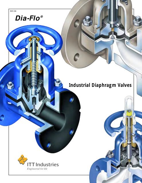
<strong>Dia</strong>-Flo ®<br />
Industrial <strong>Dia</strong>phragm Valves
DIA-FLO ® DIAPHRAGM VALVES<br />
Chemical: <strong>Dia</strong>-Flo <strong>Dia</strong>phragm Valves,<br />
available in a wide variety of metals, solid<br />
plastics, plastic, rubber and glass linings,<br />
are well suited to the handling of multiple<br />
chemical applications. Sulfuric<br />
acid, hydrochloric acid,<br />
hydrofluoric acid, and sodium<br />
hydroxide are typical applications<br />
handled by <strong>Dia</strong>-Flo <strong>Dia</strong>phragm<br />
Valves. The broad selection of<br />
body materials and<br />
diaphragms typically provides<br />
a chemically compatible and<br />
economical solution for<br />
almost any process system<br />
not exceeding 200 psi (13.8<br />
bar) or 350ºF (177ºC) 1 . Available in weir and<br />
straightway designs, both manual or automated,<br />
the <strong>Dia</strong>-Flo <strong>Dia</strong>phragm Valve is capable of<br />
handling clear fluids as well as slurries.<br />
Water Treatment: <strong>Dia</strong>-Flo <strong>Dia</strong>phragm<br />
Valves, due to their versatility in body and<br />
diaphragm materials, provide an<br />
economical solution for<br />
demineralizers,<br />
deionizers, reverse<br />
osmosis systems<br />
and filtration<br />
systems. The typical<br />
valves utilized in these<br />
systems are <strong>Dia</strong>-Flo Weir<br />
<strong>Dia</strong>phragm Valves with PP<br />
(Polypropylene) or Tefzel ® ETFE<br />
lining, Teflon ® PTFE or<br />
EPDM diaphragms<br />
with either manually<br />
operated or <strong>Dia</strong>-<br />
Flo pneumatically<br />
operated actuators.<br />
Typical accessories<br />
include limit switches,<br />
adjustable opening stops and handwheel opening<br />
devices.<br />
Power: <strong>Dia</strong>-Flo <strong>Dia</strong>phragm Valves are used<br />
extensively in demineralizer systems,<br />
FGD (flue gas desulfurization)<br />
systems, chemical<br />
systems and radioactive<br />
waste handling<br />
systems. The typical<br />
valve selected by OEMs<br />
and end users for<br />
demineralizers are <strong>Dia</strong>-Flo<br />
Weir <strong>Dia</strong>phragm Valves with<br />
PP or Tefzel ® ETFE lining,<br />
Teflon ® PTFE or EPDM<br />
diaphragms with <strong>Dia</strong>-Flo<br />
pneumatic actuators and<br />
required accessories.<br />
FGD systems commonly<br />
utilize <strong>Dia</strong>-Flo Straightway<br />
Valves with rubber<br />
linings to handle<br />
abrasive and<br />
corrosive process<br />
media. The nuclear<br />
industry utilizes the <strong>Dia</strong>-Flo<br />
<strong>Dia</strong>phragm Valve manufactured in<br />
accordance with nuclear standards. ITT<br />
Engineered Valves Group maintains an “N”<br />
stamp.<br />
Pulp & Paper: One of the largest industry<br />
users of chemicals, pulp and<br />
paper plants frequently utilize<br />
<strong>Dia</strong>-Flo <strong>Dia</strong>phragm Valves in<br />
water treatment, chemical, bleaching<br />
and coating processes. The <strong>Dia</strong>-<br />
Flo Straightway Valve is utilized for<br />
slurry services, such as titanium<br />
dioxide and lime mud. The<br />
<strong>Dia</strong>-Flo Weir Valve is utilized in<br />
clear fluid services typical of<br />
the water treatment,<br />
chemical handling and<br />
coating processes.
Mining: <strong>Dia</strong>-Flo <strong>Dia</strong>phragm Valves,<br />
both weir and straightway, are installed<br />
in various process lines within<br />
gold, copper, zinc and<br />
phosphate mines. Common<br />
applications include chemical<br />
feed, process feed, metal<br />
refinery, and filter press lines.<br />
The <strong>Dia</strong>-Flo Straightway<br />
<strong>Dia</strong>phragm Valve, due to<br />
the unobstructed flow<br />
path and minimal cavities,<br />
is well suited for handling<br />
abrasive and corrosive slurry<br />
applications in line sizes 1/2" to<br />
12". The chemical feed and process<br />
feed areas typically utilize clearer fluids and utilize<br />
the <strong>Dia</strong>-Flo Weir <strong>Dia</strong>phragm Valve.<br />
Pharmaceutical and Bioprocessing:<br />
Due to the streamlined flow path and minimal<br />
cavities, Pure-Flo ® hygienic diaphragm valves<br />
minimize contamination and micro-organism<br />
growth in high purity water systems. Available in<br />
316L stainless steel forged and cast bodies with<br />
either quick disconnect or buttweld end<br />
connections, the Pure-Flo diaphragm valve and<br />
Pure-Flo fabrications are designed to minimize<br />
contact surfaces, hold-up volume and space<br />
envelope. All contact materials are FDA<br />
compliant. <strong>Dia</strong>-Flo Weir <strong>Dia</strong>phragm Valves are<br />
commonly utilized on the chemical side of<br />
pharmaceutical manufacturing. Similar to the<br />
Pure-Flo hygienic diaphragm valve, <strong>Dia</strong>-Flo<br />
<strong>Dia</strong>phragm Valves are available in FDA compliant<br />
body and diaphragm materials. FDA compliant<br />
plastic linings, solid plastic and 316 stainless<br />
steel body materials are available.<br />
Electronics: The stringent cleanliness<br />
requirements of the high purity water and high<br />
purity chemical systems in the semiconductor<br />
industry may be met with the <strong>Dia</strong>-Flo solid<br />
plastic weir diaphragm valve.<br />
Available in four solid plastic<br />
materials, including<br />
unpigmented grade 6000HD<br />
PVDF, the <strong>Dia</strong>-Flo <strong>Dia</strong>phragm<br />
Valve with a two-piece<br />
Teflon ® PTFE diaphragm<br />
minimizes particle<br />
generation and<br />
entrapment.<br />
1 These pressure/temperature limitations are not permissible at<br />
the same time. Consult the <strong>Dia</strong>-Flo Technical Manual for individual<br />
P/T limitations.<br />
Table of Contents<br />
Weir Valves . . . . . . . . . . . . . . . . . . . 2<br />
Solid Plastic Valves . . . . . . . . . . . . . 4<br />
Straightway Valves . . . . . . . . . . . . . 6<br />
Actuated Valves . . . . . . . . . . . . . . . 8<br />
Dualrange ® Control Valves . . . . . 10<br />
<strong>Dia</strong>phragm Selections . . . . . . . . . 12<br />
Technical Data . . . . . . . . . . . . . . . 13<br />
Ordering Information . . . . . . . . . 14<br />
Teflon ® is a registered trademark of DuPont.
2<br />
DIA-FLO ® WEIR<br />
DIAPHRAGM VALVES<br />
Features and Benefits<br />
The <strong>Dia</strong>-Flo <strong>Dia</strong>phragm Valve is typically one of the most economical<br />
valve solutions in chemical applications due to the<br />
wide choice of wetted materials.<br />
• Acids<br />
• Caustics<br />
• High purity chemicals<br />
• Agricultural chemicals<br />
• Demineralizer systems<br />
• Plastics manufacturing<br />
Common Applications<br />
• Flue Gas Desulfurization (FGD)<br />
– Mist eliminator<br />
– Recycled water<br />
• Rubber manufacturing<br />
• Chlorine manufacturing<br />
• Broad Material Availability: Given the various body and<br />
diaphragm materials, the <strong>Dia</strong>-Flo <strong>Dia</strong>phragm Valve often provides<br />
the most economical solution for your process system,<br />
within the valve’s design parameters. See page 15 for specific<br />
materials, end connections, and sizes.<br />
• Slurry Applications: Due to the streamlined flow path<br />
and virtual absence of cavities, the diaphragm valve is ideal<br />
for slurry applications. Cavities within valves tend to entrap<br />
solids, either increasing the valve’s operational torque or<br />
inhibiting operation. The <strong>Dia</strong>-Flo Weir <strong>Dia</strong>phragm Valve is<br />
recommended for slurries containing 15% or less solids. For<br />
slurries exceeding 15% solids, the <strong>Dia</strong>-Flo Straightway<br />
<strong>Dia</strong>phragm Valve is recommended.<br />
• High Purity Applications: The <strong>Dia</strong>-Flo <strong>Dia</strong>phragm<br />
Valve is the proven selection to minimize particle<br />
generation and product entrapment inherent to<br />
other valve types.<br />
• Corrosive Applications: A broad selection<br />
of plastic linings and PTFE diaphragms,<br />
coupled with our corrosion resistant coatings,<br />
provide an excellent barrier to chemical<br />
attack and corrosion. In addition to<br />
our standard blue primer coating, PVDF<br />
and white epoxy coatings are available.<br />
• Bubble Tight Shut-off: <strong>Dia</strong>-Flo Weir<br />
<strong>Dia</strong>phragm Valves provide bubble tight<br />
shut-off from 0.1 micron to 200 psi line in<br />
accordance with MSS SP-88<br />
(Manufacturers Standardization Society of<br />
the Valves and Fittings Industry, Inc. Standard<br />
Practice– <strong>Dia</strong>phragm Valves).<br />
• Bonnet Isolation: Working parts are isolated from<br />
the process fluid.<br />
• Secondary Containment: The optional sealed bonnet provides<br />
a secondary containment boundary in the case of<br />
diaphragm failure; preventing the process media from entering<br />
the atmosphere.<br />
• Unique Features: Unique features which optimize the valve<br />
per-formance and life, varying by valve size are: adjustable travel<br />
stop, protective stem cap, o-ring sealed stem, bronze bushing,<br />
Line-Lok ® for plastic lined valves, yellow position indicator,<br />
molded closed diaphragms, and PVDF corrosion resistant coating.<br />
• Vacuum Applications: The diaphragm valve is capable of<br />
bubble-tight shut-off down to 0.1 micron. Elastomer or<br />
Teflon ® PTFE diaphragms may be used. The in-leakage rate is<br />
less than 1 x 10 - 6<br />
cc-atm/sec for elastomer diaphragms and can<br />
be less upon request.
3<br />
Materials<br />
PARTS<br />
Item Description Material Quantity<br />
1 Protective Cap Acrylic or Polysulfone* 1<br />
2 Adjustable Travel Stop Steel, Stainless Steel* 1<br />
3 Stem Steel, Stainless Steel* 1<br />
4 Bushing Bronze, Stainless Steel* 1<br />
5 Seal, Wiper Polyolefin Foam, FKM* 1<br />
6 O-Ring** Buna N, EPDM*, FKM* 1<br />
7 V-Notch Vent Plug Stainless Steel AR<br />
8 Handwheel Cast Iron or PAS, Stainless Steel*, Bronze*, PP† 1<br />
9 Bonnet Cast Iron, Ductile Iron*, PAS†, PP†, Stainless Steel*, Bronze* 1<br />
10 Compressor Cast Iron or Zinc, Bronze*, PVDF Coated Cast Iron* 1<br />
11 Spirol Pin Stainless Steel 1<br />
12 <strong>Dia</strong>phragm** Elastomer, PTFE 1<br />
13 Tube Nut Brass, Stainless Steel* AR<br />
14 Set Screw Stainless Steel SD<br />
15 O-Ring** Buna N, EPDM*, FKM* 1<br />
16 Thrust Washer Steel, Stainless Steel* 1<br />
17 O-Ring** Buna N, EPDM*, FKM* 1<br />
18 Washer, Shim Polyethylene AR<br />
19 Bearing, Thrust Carbon Steel 1<br />
20 Cap, Indicating Vinyl 1<br />
N/S Bolting & Nuts Steel, Stainless Steel* SD<br />
*Optional materials. †Solid plastic body only. AR—As required SD—Size dependent **Recommended spare parts.<br />
PARTS<br />
Item Description Material Quantity<br />
1 Body Flange Various 1<br />
2 <strong>Dia</strong>phragm** Elastomer, PTFE 1<br />
3 O-Ring** Buna N 1<br />
4 Nuts Steel 14<br />
5 Studs Steel 14<br />
6 Bonnet Cast Iron 1<br />
7 Compressor Cast Iron 1<br />
8 Pin Stainless Steel 1<br />
9 Spindle Steel 1<br />
10 Handwheel Cast Iron 1<br />
11 Bushing Brass 1<br />
12 Screw, set Steel 1<br />
13 Hub, Handwheel Cast Iron 1<br />
14 Key, Handwheel Steel 1<br />
15 Fitting Lube Steel 1<br />
17 Collar, Stop Steel 1<br />
18 Spindle, Extension, Ind. Stainless Steel 1<br />
19 Nut, Bushing Brass 1<br />
20 O-Ring**† Elastomer 1<br />
21 Bearing, Ball Thrust Steel 1<br />
22 Bolt Steel 6<br />
23 Lockwasher Steel 6<br />
24 Nut Steel 6<br />
25 Key, Tube Nut Brass 1<br />
26 Nut, Tube Brass 1<br />
**Recommended spare parts.<br />
Cv Values<br />
†For sealed bonnet only.<br />
WEIR VALVE Cv RATINGS (100% OPEN)<br />
Item 1/2 3/4 1 11/4 11/2 2 21/2 3 4 6 8 10 12<br />
Flanged<br />
Unlined<br />
5.5 22 22 56 56 70 160 190 310 600 1200 1800 2550<br />
Flanged<br />
Plastic Lined<br />
— 10 10 38 38 67 100 175 285 690 1070 — —<br />
Flanged<br />
PFA Lined<br />
— — 12 — 34 61 — 150 365 738 — — —<br />
Flanged<br />
Hard Rubber 4.0 10 10 31 31 55 115 160 260 625 1150 1750 2350<br />
Lined<br />
Flanged<br />
Soft Rubber 2.0 7.0 7.0 25 25 50 110 155 250 515 1150 1750 2350<br />
Lined<br />
Flanged<br />
Glass Lined<br />
5.5 22 22 53 53 78 180 250 420 850 1700 — —<br />
Screwed End 4.4 10 19 48 48 70 95 172 — — — — —<br />
Butt Weld 3.5 7.5 18.6 — 48 70 95 180 400 600* 1200* — —<br />
*Data is based on estimates.<br />
902 Bonnet<br />
6" through 12" standard<br />
Pressure psig<br />
PT Curve<br />
0<br />
220<br />
200<br />
180<br />
160<br />
140<br />
120<br />
100<br />
80<br />
60<br />
40<br />
20<br />
0<br />
0<br />
-7<br />
4<br />
903 Bonnet<br />
1/2" through 4" standard<br />
Consult factory for 6"<br />
Temperature C<br />
15 27 38 49 60 71 82 93 104 115 127 138 149 160 171 182<br />
15.2<br />
0.5-1<br />
1.25-2<br />
4<br />
6<br />
8<br />
10-12<br />
0.0<br />
20 40 60 80 100 120 140 160 180 200 220 240 260 280 300 320 340 360<br />
Temperature F<br />
2.5-3<br />
13.8<br />
12.4<br />
11.0<br />
9.6<br />
8.3<br />
6.9<br />
5.5<br />
4.1<br />
2.7<br />
1.4<br />
Pressure bar
4<br />
DIA-FLO ® SOLID PLASTIC<br />
DIAPHRAGM VALVES<br />
Common Applications<br />
• High purity water systems<br />
• High purity chemical systems<br />
• General chemicals<br />
– Hydrochloric acid<br />
– Sulfuric acid<br />
Features and Benefits<br />
<strong>Dia</strong>-Flo Solid Plastic <strong>Dia</strong>phragm Valves, ideal for solid plastic piping<br />
systems in sizes 1/2" - 4", are process proven in chemical and<br />
high purity applications.<br />
• Body Materials: Available in PVC (polyvinyl chloride), CPVC<br />
(chlorinated polyvinyl chloride), PP (polypropylene) and unpigmented<br />
PVDF (polyvinylidiene fluoride).<br />
• <strong>Dia</strong>phragm Materials: Identical to the <strong>Dia</strong>-Flo Weir <strong>Dia</strong>phragm<br />
Valve offering, elastomeric and PTFE (polymerized tetrafluoroethylene)<br />
diaphragms are available to suit almost any process system.<br />
• Bonnet Materials: Two bonnets molded from glass reinforced<br />
polymers are available to provide the most economical and temperature<br />
resistant solution. PP is the economical solution for line<br />
temperatures up to 200ºF (93ºC). For higher line temperatures up<br />
to 275ºF (135ºC), the thermoplastic material, PAS (polyarylsulfone)<br />
is recommended.<br />
• End Connections: Available in flanged, threaded, socket and<br />
spigot weld end connections. Flanged end connections are<br />
compliant with ANSI 150# dimensions. Threaded end connections<br />
are compliant with NPT (National Pipe Thread)<br />
standards. Socket weld end connections are schedule 80.<br />
PVC and CPVC spigot weld end connections are schedule<br />
80. PP and PVDF spigot weld end connections meet<br />
DIN SDR 11 dimensions.<br />
• Increased Flange Strength: PP and PVDF bodies<br />
feature PVDF-coated steel flanges for increased<br />
mechanical strength and sealing properties. This<br />
is especially advantageous in fiberglass-reinforced<br />
plastic piping systems and thermocycling services.<br />
• Actuation: The solid plastic Advantage ® Actuator<br />
and standard <strong>Dia</strong>-Flo actuator are both available<br />
with the solid plastic diaphragm valve. The<br />
Advantage Actuator provides a lightweight, compact,<br />
durable solution. The 1/2" - 2" actuator is molded from<br />
a high-strength, glass-reinforced thermoplastic polymer,<br />
PAS (polyarylsulfone) capable of maximum line temperatures<br />
up to 275ºF (135ºC). In sizes 3" - 4", the actuator is molded from<br />
a vinylester thermoset plastic capable of maximum line temperatures<br />
up to 275ºF (135ºC). Pneumatically operated and<br />
diaphragm driven, the actuators are available in three modes of<br />
operation: Failed Closed (Reverse), Fail Open (Direct) and Double<br />
Acting. For details on the <strong>Dia</strong>-Flo Actuator, refer to pages 8 and<br />
9.<br />
• Actuator Accessories: Adjustable travel stops, adjustable opening<br />
stops, manual overrides, limit switches and positioners are<br />
available to meet your process needs. Limit switches, both<br />
mechanical and proximity, are available in designs compliant with<br />
NEMA (4, 4X, 7, 9) and NEC (Class I, Division 1 and 2). For control<br />
applications, the Advantage Actuator with Moore Products positioner<br />
is available in sizes 3/4" through 4".<br />
• Size: The <strong>Dia</strong>-Flo Solid Plastic <strong>Dia</strong>phragm Valve is available in<br />
sizes 1/2"- 4". See page 15 for specific material, end connection<br />
and size availability.
5<br />
Materials<br />
PARTS<br />
Item Description Material Quantity<br />
1 Bonnet Polypropylene 1<br />
2 Handwheel Polypropylene 1<br />
3 Cap Acrylic, Clear 1<br />
4 Spindle Carbon Steel 1<br />
5 Bushing Brass 1<br />
6 Compressor Zinc 1<br />
7 <strong>Dia</strong>phragm* As Specified 1<br />
8 Bearing, Thrust Carbon Steel 1<br />
9 Washer, Shim Polyethylene AR<br />
10 Seal, Wiper Polyolefin Foam 1<br />
11 Pin, Spirol Stainless Steel 1<br />
12 Scr., Set Hex Sdc. Stainless Steel SD<br />
13 Scr., Hex Hd. Cap Stainless Steel SD<br />
14 Washer, Plain Stainless Steel SD<br />
15 Washer Stainless Steel 1<br />
16 Adjustable Travel Stop Stainless Steel 1<br />
17 Nut, Hex Stainless Steel SD<br />
18 Cap Silicone SD<br />
19 O-Ring*, (Spindle) Buna N 1<br />
20 O-Ring*, (Cap) Buna N 1<br />
21 O-Ring*, (Bushing) Buna N 1<br />
22 Body PP, PVDF, CPVC, & PVC 1<br />
*Recommended spare parts.<br />
SD—Size Dependent<br />
1/2" through 4"<br />
BODY MATERIAL SPECIFICATIONS<br />
Specification PVC CPVC PP PVDF<br />
ASTM D1784 D1784 D4101 D3222<br />
Grade 12454A 23547B Homopolymer Homopolymer<br />
FDA CFR Title 21 — — 177.1520 177.2510<br />
Cv Values<br />
SOLID PLASTIC VALVE Cv RATINGS<br />
% Open 1 /2 3 /4 1 1 1 /4 1 1 /2 2 3 4<br />
100 3.60 8.70 15.80 28.40 31.50 65.50 125 185<br />
PT Curve<br />
-18<br />
160<br />
-7<br />
4<br />
15<br />
27<br />
38<br />
Temperature C<br />
49 60 71<br />
82<br />
93*<br />
104<br />
115<br />
127<br />
138<br />
11.0<br />
Advantage Actuator 1/2" through 2"<br />
(Fail Closed Shown)<br />
140<br />
9.6<br />
Pressure psig<br />
120<br />
100<br />
80<br />
60<br />
PVC<br />
PP<br />
PVDF<br />
CPVC<br />
8.3<br />
6.9<br />
5.5<br />
4.1<br />
Pressure bar<br />
40<br />
2.7<br />
20<br />
1.4<br />
0<br />
0<br />
20<br />
40<br />
60 80 100 120 140 160 180 200* 220<br />
Temperature F<br />
*PAS *PAS Bonnet required above 200°F F (93 (93°C)<br />
240<br />
260<br />
0.0<br />
280<br />
Advantage Actuator 3" and 4"<br />
(Fail Open Shown)
6<br />
DIA-FLO ® STRAIGHTWAY<br />
DIAPHRAGM VALVES<br />
Common Applications<br />
• Titanium dioxide (TiO2)<br />
• Flue Gas Desulfurization<br />
(FGD)<br />
• Fly ash<br />
• Limestone slurry<br />
• Fertilizers: phosphate,<br />
anhydrous ammonia<br />
• Slurry services<br />
• Abrasive services<br />
Features and Benefits<br />
Ideal for slurry, abrasive and corrosive applications, the <strong>Dia</strong>-<br />
Flo Straightway <strong>Dia</strong>phragm Valve provides the following<br />
benefits:<br />
• Slurry Applications: Due to the streamlined fluid passage,<br />
the <strong>Dia</strong>-Flo Straightway Valve can handle slurries,<br />
without solid particles becoming entrapped in cavities or<br />
crevices which may obstruct the operation of other valve<br />
types. In addition, the unobstructed flow path allows the<br />
valve to be rodded through.<br />
• Abrasion Resistant: Available in five rubber linings: Soft<br />
Rubber, Hard Rubber, Neoprene ® , Hypalon ® and Butyl, the<br />
Straightway Valve is well suited to handling corrosive and<br />
abrasive services.<br />
• Corrosive Resistant: In addition to the rubber linings,<br />
Tefzel ® ETFE, polypropylene, and glass linings are available to<br />
handle the most corrosive services. To protect the valve exterior,<br />
PVDF and white epoxy coatings are available.<br />
• Conventional Straightway Design: The <strong>Dia</strong>-Flo Straightway<br />
Valve is a conventional design as opposed to a reduced<br />
port straightway design. A reduced port straightway<br />
design is similar to a pre-pinched pinch<br />
valve, in that the flow path cross-sectional<br />
area is generally reduced. The reduction<br />
in area results in reduced flow capacity<br />
(Cv), increased velocity, increased pressure<br />
drop and accelerated wear<br />
through the valve.<br />
• Bonnet Isolation: Similar to the weir<br />
valve, the working parts of the bonnet<br />
are completely isolated from the<br />
process media. Thus, in slurry or corrosive<br />
applications, the media can not<br />
adversely affect the operation of the<br />
valve internals, by either clogging or corroding<br />
them.<br />
• Bubble-Tight Shut-Off: 100% seat and<br />
shell testing is performed on every assembly<br />
to verify bubble-tight shut-off. Testing is<br />
performed in accordance with MSS SP-88<br />
(Manufacturers Standardization Society of the<br />
Valve and Fittings Industry, Inc., Standard Practice -<br />
<strong>Dia</strong>phragm Valves).<br />
• Valve Options: Adjustable travel stop, sealed bonnet,<br />
alternate materials, alternate coatings and chainwheel operated<br />
are options that can be specified with a manual valve.<br />
For valve automation refer to pages 8 and 9.<br />
• Sizes: Rubber-lined bodies are available in sizes 1"–12".<br />
Metal flanged end bodies are available in 1/2"–12". Plastic<br />
and glass lined bodies are available in 1"– 8". Screwed metal<br />
bodies are available in 1/2"–2". Refer to page 18 for material<br />
details.
7<br />
Cv Values<br />
STRAIGHTWAY VALVE Cv RATINGS (100% OPEN)<br />
Item 1/2 1 11/2 2 21/2 3 4 6 8 10 12<br />
Flanged<br />
Unlined<br />
11 60 115 275 450 525 700 2250 4250 5000 5000<br />
Flanged<br />
Plastic Lined<br />
— 24 80 209 — 370 569 1400 2644** — —<br />
Flanged<br />
Hard* Rubber — 55 130 260 365 460 700 1800 3500 4850 4850<br />
Lined<br />
Flanged<br />
Soft* Rubber — 42 79 220 365 460 700 1800 3500 4850 4850<br />
Lined<br />
Flanged<br />
Glass Lined<br />
— 48 100 270 425 475 700 1950 4400 — —<br />
Screwed End 15 39 120 265 — — — — — — —<br />
*Note: Flanged Soft Rubber = soft natural rubber, Neoprene ® , Hypalon ® and Butyl linings.<br />
Flanged Hard Rubber = hard natural rubber lining.<br />
**Note: Data is based on estimates.<br />
Materials<br />
PARTS<br />
Item Description Material Quantity<br />
1 Body Flanged Cast Iron 1<br />
2 Bonnet Cast Iron 1<br />
3 Compressor Cast iron 1<br />
4 <strong>Dia</strong>phragm Elastomer 1<br />
5 Bushing Brass 1<br />
6 Handwheel Cast Iron 1<br />
7 Spindle Steel 1<br />
8 Spindle, Extension (indicating) Stainless Steel 1<br />
9 Insert Steel 1<br />
10 Spacer Steel 1<br />
11 Pin, Spirol Stainless Steel 1<br />
12 Washer, Shim Polyethylene AR<br />
13 Bearing, Thrust Needle Steel 1<br />
14 Bearing, Thrust Race Steel 2<br />
15 Screw, Set Hex. Soc. Steel 2<br />
16 Fitting, Lube Steel 1<br />
17 Screw, Hex, Ho, Cp Steel SD<br />
18 Nut, Hex. Steel SD<br />
19 Pin, Spirol Stainless Steel 1<br />
20 Capseal Brass 1<br />
AR—As Required<br />
SD—Size Dependent<br />
PT Curve<br />
-18 -4<br />
120<br />
10<br />
24<br />
Temperature C<br />
38 52 65<br />
79 93 107 121<br />
8.3<br />
Standard 902 bonnet is shown.<br />
903 bonnet features an extended stem<br />
and travel stop.<br />
100<br />
2.5-3<br />
6.9<br />
80<br />
4<br />
0.5-2<br />
5.5<br />
Pressure psig<br />
60<br />
40<br />
8<br />
10-12<br />
6<br />
4.1<br />
2.7<br />
Pressure bar<br />
20<br />
1.4<br />
0<br />
0<br />
25<br />
50<br />
75<br />
100 125 150<br />
Temperature F<br />
0.0<br />
175 200 225 250
8<br />
DIA-FLO ® ACTUATED<br />
DIAPHRAGM VALVES<br />
Features and Benefits<br />
The <strong>Dia</strong>-Flo Actuator has been field tested and proven to be<br />
durable and long lasting. More than 20 years of service is not<br />
uncommon.<br />
• Long Lasting: Pneumatically operated and diaphragm driven, the<br />
<strong>Dia</strong>-Flo actuator provides long service life with minimal maintenance.<br />
The actuator wear parts are limited to only the nylon-reinforced<br />
Buna N ® diaphragm and Buna N ® o-rings which require<br />
infrequent replacement.<br />
• 3 Modes of Operation: Fail Closed (spring-to-close, air-to-open),<br />
Fail Open (spring-to-open, air-to-close) and Double Acting (air-toopen,<br />
air-to-close) models are available to accommodate almost<br />
any system design. Fail Closed, the most frequently ordered mode<br />
of operation, assures a bubble-tight shut-off in the case of supply<br />
air pressure loss.<br />
• 8 Available Sizes: The wide selection of sizes accommodates<br />
almost any combination of line pressure and supply pressure.<br />
Maximum supply pressure, either pneumatic or hydraulic is 85 psig<br />
(5.86 bar). For actuator sizing, refer to our <strong>Dia</strong>-Flo Technical Manual<br />
or contact your local distributor or Technical Sales Representative.<br />
• Maintenance: Maintenance of the <strong>Dia</strong>-Flo actuator is typically<br />
minimal, requiring only periodic lubrication and occasional<br />
diaphragm and o-ring replacement.<br />
• Corrosion Resistance: PVDF and white epoxy coatings<br />
are available to protect the actuator and valve assembly<br />
from hazardous environments.<br />
• Mechanical Accessories: Adjustable opening stops,<br />
adjustable travel stops, manual overrides, position<br />
indicators and yoke mountings are available to meet<br />
your processing requirements.<br />
• Instrumentation: Limit switches, both mechanical and<br />
proximity, capable of meeting Nema 4, 4X, 7, 9, 13 and NEC<br />
(National Electrical Code) Class I, Division 1 and 2 are available in a<br />
variety of choices to meet your system requirements. In addition,<br />
solenoids, air filter regulators, transducers, positioners, speed control<br />
valves and snap-acting relays may also be factory mounted.
9<br />
Direct Acting 3100 Series<br />
Fail Open<br />
Reverse Acting 3200 Series<br />
Fail Closed<br />
Double Acting 3300 Series<br />
Materials<br />
PARTS<br />
Item Description Material Quantity<br />
1 Safety Cap Steel 1<br />
2 Spring Rod Steel 1<br />
3 Jam Nut Steel 1<br />
4 Travel Stop Steel 1<br />
5 Top Cover Aluminum, Ductile Iron* 1<br />
6 Springs Steel AR<br />
7 Spindle Nut Steel 1<br />
8 Spring Seat Cast Iron 1<br />
9 Actuator <strong>Dia</strong>phragm Buna N 1<br />
10 O-Ring Buna N, EPDM*, FKM* 1<br />
11 O-Ring Buna N 1<br />
12 Bonnet Assembly — 1<br />
13 <strong>Dia</strong>phragm Elastomer, FKM*, PTFE* 1<br />
14 Body Cast Iron, Ductile Iron, Stainless Steel, Steel 1<br />
15 Thrust Washer Steel 1<br />
16 Cap Screw Steel 2<br />
17 Spirol Pin Stainless Steel 1<br />
18 Nut Steel, Stainless Steel* SD<br />
19 Compressor Zinc, Cast Iron, Bronze* 1<br />
20 Bolt Steel, Stainless Steel* SD<br />
21 Bolt Steel, Stainless Steel* SD<br />
22 Nut Steel, Stainless Steel* SD<br />
23 Nut Steel 1<br />
24 Lube Fitting Steel 1<br />
25 Spindle Steel, Stainless Steel* 1<br />
26 Bushing Steel, Stainless Steel* 1<br />
* Optional material AR—As Required SD—Size Dependent<br />
Cv Values & PT Curve<br />
For Cv Values and P/T limitations, please refer to body types:<br />
— Weir <strong>Dia</strong>phragm Valve pages 2-3<br />
— Solid Plastic <strong>Dia</strong>phragm Valve pages 4-5<br />
— Straightway <strong>Dia</strong>phragm Valve pages 6-7<br />
Maximum housing pressure is 85 psig
10<br />
DIA-FLO ® DUALRANGE ® CONTROL VALVE<br />
Features and Benefits<br />
The Dualrange Control Valve combines the standard features of the weir<br />
diaphragm valve with increased rangeability. Utilizing a unique two-piece<br />
compressor design, the Dualrange Control Valve has greater rangeability<br />
and controllability than typical diaphragm valves. Notable applications and<br />
benefits are as follows:<br />
• Control: The unique bonnet design encompasses two nested compressors<br />
as opposed to one utilized in conventional diaphragm valves. The individual<br />
movement of each compressor allows an increase in rangeability over conventional<br />
diaphragm valves. When an increase in flow is desired, the inner compressor<br />
moves completely upward, followed by the outer compressor. This<br />
dual movement allows greater variance in the flow path cross-sectional area,<br />
which directly corresponds to greater variances in flow. Hence increased controllability<br />
is achieved.<br />
• Cleanability: The streamlined flow path allows the control of high purity<br />
services while still maintaining stringent cleanliness requirements.<br />
• Slurries and Abrasives: Given the relative absence of cavities and crevices,<br />
the Dualrange Control Valve is ideal for controlling slurries up to 15% in solid<br />
concentration.<br />
• Positioners: The ITT Conoflow and Moore Products positioners are available<br />
as standard with the Dualrange Control Valve. Other positioners are available<br />
upon request.<br />
• Maintenance: The Dualrange utilizes standard <strong>Dia</strong>-Flo actuators and weir<br />
diaphragms. Therefore, part interchangability and maintenance are standardized.<br />
Typically, only periodic lubrication and diaphragm and o-ring replacement<br />
are required.<br />
• Control Valve Sizing: To optimize the desired control within your system<br />
parameters, please contact us to perform sizing calculations and offer valve<br />
recommendations.<br />
• Sizes: The Dualrange is available with all weir style bodies and diaphragms<br />
in sizes 1" - 6".<br />
Dualrange ® vs Conventional Weir Valve<br />
Dualrange<br />
Conventional<br />
Fine Throttling<br />
Dualrange<br />
Conventional<br />
Full Open
11<br />
Cv Values<br />
FLANGED UNLINED<br />
% open 3/4–1 11/2 2 21/2 3 4 6<br />
10 1.0 2.0 4.0 8.0 14 24 65<br />
20 3.2 8.0 9.0 18 27 47 125<br />
30 5.2 14 14 28 42 70 255<br />
40 7.4 21 19 52 68 130 365<br />
50 9.4 33 33 78 97 185 445<br />
60 13 43 50 105 120 245 515<br />
70 18 50 62 130 145 275 550<br />
80 21 52 69 150 160 295 570<br />
90 22 54 70 160 175 305 590<br />
100 22 56 70 160 190 310 600<br />
FLANGED GLASS LINED<br />
% open 3/4–1 11/2 2 21/2 3 4 6<br />
10 1.4 3.0 3.0 8.0 12 24 98<br />
20 3.8 9.0 9.0 18 32 50 190<br />
30 6.2 16 17 28 48 77 370<br />
40 8.6 26 25 56 84 145 520<br />
50 12 40 40 85 135 210 640<br />
60 18 51 62 115 185 270 750<br />
70 22 54 75 140 220 335 805<br />
80 22 55 82 155 240 395 835<br />
90 22 54 82 180 245 415 845<br />
100 22 53 78 180 250 420 850<br />
FLANGED SOFT RUBBER LINED<br />
% open 3/4–1 11/2 2 21/2 3 4 6<br />
10 0.5 3.0 3.5 6.0 12 22 65<br />
20 1.6 8.0 10 15 26 41 125<br />
30 3.2 14 17 25 39 60 250<br />
40 5.5 20 23 47 55 105 350<br />
50 6.2 29 33 76 77 155 405<br />
60 6.9 28 47 95 99 195 450<br />
70 7.1 26 54 105 120 220 485<br />
80 7.2 26 54 110 135 240 505<br />
90 7.1 25 52 110 145 245 510<br />
100 7.0 25 50 110 155 250 515<br />
FLANGED HARD RUBBER LINED<br />
% open 3/4–1 11/2 2 21/2 3 4 6<br />
10 0.5 3.5 6.0 10 12 25 65<br />
20 3.0 10 12 20 26 50 130<br />
30 5.9 16 17 30 40 71 275<br />
40 8.3 26 22 49 57 130 430<br />
50 10 29 37 65 84 190 530<br />
60 11 29 51 84 110 230 570<br />
70 11 30 60 96 125 245 590<br />
80 11 30 60 105 145 250 620<br />
90 10 31 59 110 155 260 625<br />
100 10 31 55 115 160 260 625<br />
FLANGED PLASTIC LINED<br />
% open 3/4–1 11/2 2 21/2 3 4 6<br />
10 1.0 3.0 4.5 7.0 16 20 70<br />
20 2.8 8.0 11 17 34 55 145<br />
30 4.7 13 16 28 52 80 280<br />
40 6.6 21 27 50 84 125 430<br />
50 8.2 32 43 75 125 190 540<br />
60 9.5 37 60 88 150 240 610<br />
70 10 38 68 97 160 270 655<br />
80 11 39 69 100 170 285 680<br />
90 10 38 69 100 175 290 690<br />
100 10 38 67 100 175 285 690<br />
FLANGED END - PFA LINED - DUALRANGE<br />
% open 1 11/2 2 3 4 6<br />
10 0.3 2 4 8 11 45<br />
20 1.0 6 12 26 32 106<br />
30 1.8 10 20 47 59 215<br />
40 3.9 19 25 88 107 407<br />
50 6.6 24 34 101 181 525<br />
60 9.5 28 49 124 262 625<br />
70 10 29 59 134 302 670<br />
80 11 31 60 141 330 698<br />
90 11 32 60 147 356 728<br />
100 12 34 61 150 365 738<br />
SOLID PLASTIC*<br />
% open 1 11/4 11/2 2 3 4<br />
10 0.26 0.40 0.60 2.00 7.90 11.10<br />
20 1.19 1.40 3.22 4.27 17.00 21.90<br />
30 2.17 3.43 5.60 8.60 29.00 36.90<br />
40 3.12 6.08 8.28 14.63 44.50 57.50<br />
50 6.09 12.12 15.78 28.71 75.00 94.30<br />
60 10.24 20.24 25.20 45.60 102.00 117.00<br />
70 13.44 24.82 29.61 56.40 117.00 135.00<br />
80 15.20 27.10 31.50 62.60 125.00 150.50<br />
90 15.80 27.70 31.50 64.00 126.00 161.00<br />
100 15.80 28.40 31.50 65.50 126.00 170.00<br />
Cv values are expressed in gpm per 1 psi pressure drop.<br />
*These values, with the exception of the 3" and 4" columns, are based<br />
on engineering estimates and not actual test data.<br />
PERCENT OPEN<br />
100<br />
90<br />
80<br />
70<br />
60<br />
50<br />
40<br />
30<br />
20<br />
10<br />
Valve Flow Characteristics<br />
EQUAL PERCENTAGE<br />
LINEAR<br />
DUAL RANGE<br />
CONVENTIONAL WEIR<br />
QUICK OPENING<br />
PERCENT OPEN<br />
100<br />
90<br />
80<br />
70<br />
60<br />
50<br />
40<br />
30<br />
20<br />
10<br />
BALL VALVE<br />
HIGH PERFORMANCE BUTTERFLY VALVE<br />
LINEAR<br />
DUAL RANGE<br />
CONVENTIONAL WEIR<br />
PT Curves<br />
Solid Plastic Body with Dualrange Actuator<br />
10 20 30 40 50 60 70 80 90 100<br />
PERCENT OF MAXIMUM Cv<br />
10 20 30 40 50 60 70 80 90 100<br />
PERCENT OF MAXIMUM Cv<br />
Weir Body with Dualrange Actuator<br />
-18<br />
110<br />
-4<br />
10<br />
24<br />
38<br />
Temperature C<br />
52 65 79<br />
93<br />
107<br />
121<br />
135<br />
149<br />
7.6<br />
-18<br />
110<br />
-4<br />
10<br />
24<br />
38<br />
52<br />
Temperature C<br />
65 79 93 107<br />
121<br />
135<br />
149<br />
163<br />
177<br />
7.6<br />
Pressure psig<br />
100<br />
90<br />
80<br />
70<br />
60<br />
50<br />
40<br />
PVC<br />
PP<br />
CPVC<br />
PVDF<br />
6.9<br />
6.2<br />
5.5<br />
4.8<br />
4.1<br />
3.4<br />
2.7<br />
Pressure bar<br />
Pressure psig<br />
100<br />
90<br />
80<br />
70<br />
60<br />
50<br />
40<br />
6<br />
2.5-3<br />
4<br />
1<br />
1.25-2<br />
6.9<br />
6.2<br />
5.5<br />
4.8<br />
4.1<br />
3.4<br />
2.7<br />
Pressure bar<br />
30<br />
2.1<br />
30<br />
2.1<br />
20<br />
1.4<br />
20<br />
1.4<br />
10<br />
0.7<br />
10<br />
0.7<br />
0<br />
0<br />
25<br />
50<br />
75<br />
100<br />
125 150 175<br />
Temperature F<br />
200<br />
225<br />
250<br />
275<br />
0.0<br />
300<br />
0<br />
0<br />
25<br />
50<br />
75<br />
100<br />
125 150 175 200<br />
Temperature F<br />
225<br />
250<br />
275<br />
300<br />
325<br />
0.0<br />
350
12<br />
DIA-FLO ® DIAPHRAGMS<br />
WEIR DIAPHRAGMS<br />
Grade Material (FDA Compliant) Size Temperature Durometer<br />
Grade B Black Butyl (FDA Compliant) 1/2-12” -20 to 250°F (-29 to 121°C) A 65-75<br />
Grade W1 White Butyl (FDA Compliant) 1/2-6” 0 to 225°F (-18 to 107°C) A 65-75<br />
Grade 17 EPDM (FDA Compliant) 1/2-4” -30 to 300°F (-34 to 149°C) A 65-75<br />
Grade M EPDM 1/2-12” -30 to 300°F (-34 to 149°C) A 60-70<br />
Grade A Soft Natural Rubber (FDA Compliant) 1/2-4” -20 to 160°F (-29 to 71°C) Faceside A 45-55<br />
Backside A 60-70<br />
Grade C Hypalon ® CSM 1/2-12” 0 to 225°F (-18 to 107°C) A 65-75<br />
Grade S Natural Rubber 1/2-10” -30 to 180°F (-34 to 82°C) A 65-75<br />
Grade T Neoprene ® 1/2-12” -20 to 200°F (-29 to 93°C) A 65-75<br />
Grade DP Buna N ® NBR (FDA Compliant) 1/2-3” 10 to 180°F (-12 to 82°C)<br />
Direct Loaded Valve only A 67-77<br />
Grade P Buna N ® NBR (FDA Compliant) 1/2-12” -10 to 180°F (-12 to 82°C) A 67-77<br />
Grade R2 PTFE (FDA Compliant) 1/2-10” -30 to 350°F (-34 to 177°C) N/A<br />
Grade TM Modified PTFE (FDA Compliant) 1/2-6” -30 to 350°F (-34 to 177°C) N/A<br />
Grade V Viton ® FKM 1/2-6” -20 to 325°F (-29 to 163°C) A 70-80<br />
STRAIGHTWAY DIAPHRAGMS<br />
Grade SB Black Butyl (FDA Compliant) 1/2-4” 0 to 200°F (-18 to 93°C) A65-75<br />
Grade SC Hypalon ® CSM 1/2-4” 0 to 180°F (-18 to 82°C) A65-75<br />
Grade SE EPDM (FDA Compliant) 1/2-12” -20 to 225°F (-29 to 107°C) A64-72<br />
Grade SP* Buna N ® NBR (FDA Compliant) 1/2-6” 10 to 180°F (-12 to 82°C) A67-77<br />
Grade SS Natural Rubber 1/2-12” -20 to 180°F (-29 to 82°C) A65-75<br />
PTFE <strong>Dia</strong>phragm Compressor Assembly<br />
showing Floating Tube Nut Design<br />
Grade ST Neoprene ® 1/2-12” -10 to 180°F (-23 to 82°C) A65-75<br />
*2.5” not available<br />
The diaphragm material and design are integral to the successful performance of the diaphragm valve. For that reason, 12 weir elastomer diaphragms,<br />
two weir PTFE diaphragms and six elastomer straightway diaphragms are available to handle a multitude of process fluids and parameters.<br />
Our elastomer diaphragms are available in a variety of materials to<br />
address various process characteristics. Some elastomer<br />
diaphragms are softer and better suited to abrasive and slurry<br />
applications. Others are harder, providing greater chemical resistivity<br />
and higher temperature limitations. All elastomer<br />
diaphragms in sizes 1" - 8" are molded in the closed position to<br />
provide the most effective seal. Each diaphragm contains markings<br />
identifying the size, material, mold date and valve supplier.<br />
To ensure the best possible diaphragm, ITT Engineered Valves<br />
maintains a continuing development program to utilize new materials<br />
and improve existing compounds. The result of this effort is<br />
the recent introduction of the PTFE grade TM diaphragm.<br />
• Proven benefits of the PTFE grade TM diaphragm versus<br />
conventional PTFE diaphragms are:<br />
— Reduced permeation due to a more homogeneous<br />
microstructure with minimal voids<br />
— Reduced cold flow similar to 25% carbon reinforced PTFE<br />
— Increased cycle life due to a more amorphous compound<br />
• The molded closed design increases the sealing properties of<br />
the diaphragm. The relaxed position of the diaphragm is contoured<br />
to the same shape as the weir which increases the ability<br />
of the diaphragm to provide a bubble-tight shut-off.<br />
• The 2-piece design includes an EPDM elastomer backing cushion<br />
and a PTFE diaphragm. This design eliminates the common<br />
problems inherent to laminated PTFE diaphragms, such as<br />
delamination, permeation, and cracking.<br />
• The floating tube nut design shown on this page prevents point<br />
loading of the PTFE diaphragms which can cause downstream<br />
leakage and premature diaphragm failure. The downward force<br />
of the stem is transferred to the compressor bypassing the tube<br />
nut. Thus, the forces are evenly distributed over the seating area<br />
of the PTFE diaphragm reducing cold flow and stud pull out<br />
problems. This same design is used on elastomer diaphragms 6"<br />
and larger.<br />
* 1/2" and 3/4" elastomer are molded open.
DIA-FLO ® TECHNICAL DATA<br />
13 10<br />
Seat & Shell Test Criteria as stated in MSS SP-88 †<br />
Test Durations and Test Pressures Based on <strong>Dia</strong>phragm Maximum Service Pressure Ratings<br />
Nominal Valve Size Maximum Pressure Shell Test Pressure Minimum Duration of Seat Test Minimum Duration of<br />
Rating psi (bar) psi (bar) Shell Test Minutes (1) Pressure psi (bar) Seal Test Minutes (1)<br />
1/2 – 1 200 (13.8) 240 (16.5) 1/4 200 (13.8) 1/4<br />
1-1/4 – 1-1/2 – 2 175 (12.1) 210 (14.5) 1/4 175 (12.1) 1/4<br />
2-1/2 – 4 150 (10.3) 180 (12.4) 1 150 (10.3) 1/2<br />
6 125 (8.6) 150 (10.3) 1 125 (8.6) 1/2<br />
8 100 (6.9) 120 (8.3) 1 100 (6.9) 1/2<br />
10 – 12 65 (4.5) 80 (5.5) 3 65 (4.5) 1/2<br />
(1)The minimum duration is the period of inspection after the valve is fully prepared and under full test pressure.<br />
Extracted from MSS SP-88-1993, with permission of the publisher, the Manufacturers Standardization Society. Reproduction prohibited under copyright convention<br />
unless written permission is granted by the Manufacturers Standardization Society of the Valve and Fittings Industry, Inc.<br />
† Valves with solid plastic bodies, plastic bonnets and/or plastic actuators are limited to 150 psi (10.3 bar) maximum.<br />
Body Materials Available<br />
Weir Bodies<br />
Body Type Material Identification* Durometer/ Maximum<br />
FDA Compliant Temperature**<br />
°F °C<br />
Metal Iron CI or GXXX 350 177<br />
Ductile Iron DI or DXXX 350 177<br />
Carbon Steel WCB or LCB 350 177<br />
Bronze B61 or B62 350 177<br />
Stainless CF8M FDA 350 177<br />
Steel 316<br />
CN7M CN7M 350 177<br />
Monel M35 350 177<br />
Hastelloy CWXM 350 177<br />
Plastic Lined PP Blue FDA 200 93<br />
PVC Grey 140 60<br />
Kynar ® PVDF White with tab FDA 285 140<br />
Tefzel ® ETFE White 300 149<br />
PFA Translucent FDA 350 177<br />
Rubber Lined Soft Natural #5 A 55-60 180 82<br />
Neoprene ® #7 A 60-65 200 93<br />
Hypalon ® CSM #9 A 60-65 200 93<br />
Hard Natural #10 D 40-70 200 93<br />
Graphite #12 D 72-78 200 93<br />
Loaded<br />
Natural<br />
Butyl #16 A 60-65 200 93<br />
Glass Lined Borosilicate Blue Glass FDA 350 177<br />
Glass<br />
Straightway Bodies<br />
Body Type Material Identification* Durometer/<br />
FDA Compliant<br />
Maximum<br />
Temperature**<br />
°F °C<br />
Metal Iron CI or GXXX 225 107<br />
Carbon Steel WCB 225 107<br />
Stainless CF8M FDA 225 107<br />
Steel 316<br />
Plastic Lined PP Blue FDA 200 93<br />
Tefzel ® ETFE White 225 107<br />
Rubber Lined Soft Natural #5 A 55-60 180 82<br />
Neoprene ® #7 A 60-65 200 93<br />
Hypalon ® CSM #9 A 60-65 200 93<br />
Hard Natural #10 D 40-70 200 93<br />
Butyl #16 A 60-65 200 93<br />
Glass Lined Borosilicate Blue glass FDA 225 107<br />
Glass<br />
*X designates a numerical value<br />
**Temperature may decrease dependent on media, pressure and valve size.<br />
Recommended Guidelines<br />
Weir Valves<br />
Maximum Velocity 25 fps for media with no suspended solids<br />
Maximum Velocity 10 fps for media with 1-15% solids<br />
Maximum Valve P 25% P inlet for throttling<br />
Maximum Solids 15%<br />
These guidelines are recommended to optimize performance and may<br />
vary dependent on exact media and conditions. The intent is to help prevent<br />
cavitation, choke flow and premature lining and diaphragm wear.<br />
Straightway Valves<br />
Maximum Velocity 25 fps for media with no suspended solids<br />
Maximum Velocity 15 fps for media 1-15% solids<br />
Maximum Velocity 10 fps for media with solids > 15%<br />
Maximum Solids 50%<br />
These guidelines are recommended to optimize performance and may<br />
vary dependent on exact media and conditions. The intent is to help prevent<br />
cavitation, choke flow and premature lining and diaphragm wear.
14<br />
DIA-FLO STRAIGHTWAY ® ORDERING DIAPHRAGM INFORMATIONVALVE<br />
Fax to: Customer Service, ITT Engineered Valves Group Fax: 717-509-2336<br />
From: _________________________________<br />
Company: _____________________________<br />
Phone: ________________________________<br />
Weir <strong>Dia</strong>phragm Valve<br />
FEATURES (BLOCK)<br />
SIZE (A)<br />
BODY (B)<br />
DIAPHRAGM (D)<br />
BONNET (E)<br />
BONNET SEAL MATERIAL (F)<br />
OPTIONAL BONNET INTERNALS (H)<br />
OPTIONAL BOLTING (G)<br />
YOKE (K)<br />
LOCKING DEVICE (L)<br />
EXTENDED STEM (M)<br />
CHAIN (CH)<br />
OPTIONAL COATINGS (N)<br />
ADAPTED FOR BUT LESS<br />
ITT AIRMOTOR (P2)<br />
NON ITT ACTUATION (R)<br />
ACTUATOR (S)<br />
AIR MOTOR (P)<br />
OPTIONAL AIRMOTOR COVERS (P1)<br />
ADVANTAGE ACTUATOR (Q)<br />
POSITION INDICATOR (T)<br />
MECHANICAL ACCESSORIES<br />
FOR ACTUATORS (V)<br />
ACT. HARDWARE OPTIONS (U)<br />
SOLENOID VALVE (W)<br />
SOLENOID VOLTAGE (X)<br />
ADAPTED FOR BUT<br />
LESS SWITCHES (Y3)<br />
LIMIT SWITCHES (Y)<br />
OPTIONAL LIMIT<br />
SWITCH POSITION (Y1)<br />
LIMIT SWITCHES,<br />
YOKE MOUNTED (Y2)<br />
ADV. SWITCH PACK SP-2 (Z)<br />
ADV. SWITCH PACK SP-2.5 (Z5)<br />
ADV. SWITCH PACK SP-3 (Z3)<br />
POSITIONER (AA)<br />
SIGNAL RANGE (AB)<br />
FILTER REGULATOR (AC)<br />
TRANSDUCER (AD)<br />
SPEED CONTROL (AE)<br />
JUNCTION BOX (AF)<br />
SPECIAL END PREPARATION (BB)<br />
DRAINS PORTS (C)<br />
CUSTOMER HOLD POINTS (CHP)<br />
SPECIAL QUALITY DOCUMENTATION (SQD)<br />
SPECIAL SERVICE/PREPARATION (SPSERV)<br />
CODE<br />
Date:__________________________________<br />
Page: _____________ of _________________<br />
P.O.#: _________________________________<br />
Straightway <strong>Dia</strong>phragm Valve<br />
FEATURES (BLOCK)<br />
SIZE (A)<br />
BODY (B)<br />
SPECIAL END PREPARATION (BB)<br />
DIAPHRAGM (D)<br />
BONNET (E)<br />
OPTIONAL BONNET SEALS (F)<br />
CHAIN (CH)<br />
OPTIONAL BONNET INTERNALS (H)<br />
OPTIONAL BOLTING (G)<br />
YOKE (K)<br />
LOCKING DEVICE (L)<br />
EXTENDED STEM (M)<br />
OPTIONAL COATINGS (N)<br />
ADAPTED FOR BUT LESS<br />
ITT AIRMOTOR (P2)<br />
NON ITT ACTUATION (R)<br />
ACTUATOR (S)<br />
AIR MOTOR (P)<br />
OPTIONAL AIRMOTOR COVERS (P1)<br />
POSITION INDICATOR (T)<br />
MECHANICAL ACCESSORIES<br />
FOR ACTUATORS (V)<br />
ACT. HARDWARE OPTIONS (U)<br />
SOLENOID VALVE (W)<br />
SOLENOID VOLTAGE (X)<br />
ADAPTED FOR BUT<br />
LESS SWITCHES (Y3)<br />
LIMIT SWITCHES (Y)<br />
OPTIONAL LIMIT<br />
SWITCH POSITION (Y1)<br />
LIMIT SWITCHES,<br />
YOKE MOUNTED (Y2)<br />
POSITIONER (AA)<br />
SIGNAL RANGE (AB)<br />
FILTER REGULATOR (AC)<br />
TRANSDUCER (AD)<br />
SPEED CONTROL (AE)<br />
JUNCTION BOX (AF)<br />
CUSTOMER HOLD POINTS (CHP)<br />
SPECIAL QUALITY DOCUMENTATION (SQD)<br />
SPECIAL SERVICE/PREPARATION (SPSERV)<br />
CODE<br />
For features not detailed on the following pages,<br />
contact the ITT Engineered Valves Group<br />
Customer Service Department at 800-366-1111 or<br />
(717) 291-1901.
DIA-FLO ® DIAPHRAGM VALVES<br />
15<br />
Weir <strong>Dia</strong>phragm Valves<br />
Weir Bodies, Unlined (Block B)<br />
Code Body Material Size<br />
NO BODY SUPPLIED<br />
2000 No Body 1/2-12"<br />
SCREWED<br />
2401 Iron 1/2-3"<br />
2402 Bronze 1/2-3"<br />
2403 Stainless Steel (316L) 1/2-3"<br />
2405 Steel (WCB) 1-3"<br />
2406 PVC 1/2-3"<br />
2407 CN7M 1/2-3"<br />
2408 Monel 1/2-3"<br />
2410 Hastelloy 1/2-3"<br />
2412 Ductile iron 1-3"<br />
2414 PP (FDA) 1/2-3"<br />
2416 CPVC 1/2-2"<br />
2417** PVDF (FDA) 1/2-2"<br />
FLANGED<br />
2431 Cast Iron 1/2-12"<br />
2432 Bronze 1/2-6"<br />
2433R Stainless Steel (316) 1/2-8"<br />
2435R Cast Steel 1/2-8"<br />
2436 Solid PVC 1/2-4"<br />
2437R CN7M 1/2-8"<br />
2438R Monel 1/2-8"<br />
2440R Hastelloy 1/2-8"<br />
2441 Ductile Iron 1/2-8"<br />
2442 Solid CPVC 1/2-2"<br />
2444 Solid PP (FDA) 1/2-4"<br />
2447** Solid PVDF (FDA) 1/2-4"<br />
SOCKET SOLDER<br />
2456 Bronze 1/2-2"<br />
SOCKETWELD<br />
2424 Solid PP (FDA) 1/2-2"<br />
2427** Solid PVDF (FDA) 1/2-2"<br />
2451 Solid PVC 1/2-2"<br />
2463 Solid CPVC 1/2-2"<br />
2470 Stainless Steel (316L) 1/2-3"<br />
2472 Cast Steel 1/2-3"<br />
2474 CN7M 1/2-3"<br />
BUTTWELD (316L)<br />
2464 Stainless Steel Sch. 5 1/2-8"<br />
2465 Stainless Steel Sch. 10 1/2-8"<br />
2466 Stainless Steel Sch. 40 1/2-8"<br />
SPIGOTWELD<br />
2443 CPVC (IPS) 1/2-2"<br />
2484 Solid PP (FDA, DIN) 1/2-2"<br />
2486 PVC (IPS) 1/2-2"<br />
2487** Solid PVDF (FDA, DIN) 1/2-2"<br />
Weir Bodies, Lined (Block B)<br />
Code Lining Material Size<br />
FLANGED CAST IRON<br />
2501 Neoprene No. 7 1/2-12"<br />
2511 Glass Lined (FDA) 1/2-8"<br />
2516 Soft Rubber No. 5 1/2-12"<br />
2521 Hard Rubber No. 10 1/2-12"<br />
2522 Butyl Lined No. 16 1/2-12"<br />
2523 Hypalon Lined No. 9 1/2-12"<br />
2536 PVC Lined 3/4-6"<br />
2538 PP Lined (FDA) 3/4-8"<br />
2539** PP Lined (FDA) 3/4-8"<br />
2529 Tefzel Lined 3/4-8"<br />
2530 Hard Rubber No. 12 1/2-12"<br />
2575** PVDF Lined (FDA) 3/4-8"<br />
FLANGED DUCTILE IRON<br />
2544 Glass Lined (FDA) 1/2-8"<br />
2550 Neoprene No. 7 1/2-8"<br />
2551 Soft Rubber No. 5 1/2-8"<br />
2552 Hard Rubber No. 10 1/2-8"<br />
2555** PVDF Lined (FDA) 3/4-8"<br />
2556 PFA Lined (FDA) 1-6"<br />
2558 PP Lined (FDA) 3/4-8"<br />
2559 Tefzel Lined 3/4-8"<br />
FLANGED CAST STEEL<br />
2545 Tefzel Lined 3/4-8"<br />
2546 PP Lined (FDA) 3/4-8"<br />
2548 PVDF Lined (FDA) 3/4-8"<br />
2563 Hard Rubber No. 10 1/2-8"<br />
2564 Hard Rubber No. 12 1/2-8"<br />
Angle Bodies, Unlined (Block B)<br />
Code Body Material Size<br />
FLANGED<br />
2611 Cast Iron 1/2-8"<br />
Angle Bodies, Lined (Block B)<br />
Code Lining Material Size<br />
FLANGED<br />
2621 Neoprene No. 7 1/2-8"<br />
2622 Glass Lined (FDA) 1/2-8"<br />
2623 Soft Rubber No. 5 1/2-8"<br />
2624 Hard Rubber No. 10 1/2-8"<br />
<strong>Dia</strong>phragms (Block D)<br />
WEIR TYPE<br />
Code Material Size<br />
A Soft Natural Rubber (FDA) 1/2-4"<br />
B Black Butyl (FDA) 1/2-12"<br />
C Hypalon 1/2-12"<br />
H EPDM (FDA) 1/2-6"<br />
17 EPDM (FDA) 1/2-4"<br />
M EPDM 1/2-12"<br />
P BUNA N (FDA) 1/2-12"<br />
S Natural Rubber 1/2-10"<br />
T Neoprene 1/2-12"<br />
WB White Butyl (FDA) 1/2-6"<br />
DP BUNA N<br />
Direct Loaded (FDA) 1/2-3"<br />
V Viton 1/2-6"<br />
R2 PTFE (FDA) 1/2-10"<br />
TM PTFE (FDA) 1/2-6"<br />
EN Elastomer<br />
Not Supplied 1/2-12"<br />
PN PTFE<br />
Not Supplied 1/2-10"<br />
Bonnets, Handwheel (Block E)<br />
Code Bonnet Description<br />
CAST IRON<br />
902 Indicating (6" - 12")<br />
902S Indicating - Sealed (6" - 12")<br />
903 Indicating with Travel Stop<br />
(1/2" - 12")<br />
903S Indicating with Travel Stop -<br />
* R - Raised Face<br />
** Unpigmented<br />
Sealed (1/2" - 12")<br />
STAINLESS STEEL (316)<br />
912 Indicating (6" - 12")<br />
912S Indicating - Sealed (6" - 12")<br />
913 Indicating with Travel Stop<br />
(1/2" - 12")<br />
913S Indicating with Travel Stop -<br />
Sealed (1/2" - 12")<br />
POLYPROPYLENE (PP)<br />
923 Indicating with Travel Stop<br />
(1/2" - 4")<br />
BRONZE<br />
933 Indicating with Travel Stop<br />
(1/2" - 4")<br />
933S Indicating with Travel Stop -<br />
Sealed (1/2" - 4")<br />
DUCTILE IRON<br />
942 Indicating (6" - 8")<br />
942S Indicating - Sealed (6" - 8")<br />
943 Indicating with Travel Stop<br />
(1/2" - 8)<br />
943S Indicating with Travel Stop -<br />
Sealed (1/2" - 8")<br />
POLYARYLSULFONE (PAS)<br />
963 Indicating with Travel Stop<br />
(1/2" - 4")<br />
963S Indicating with Travel Stop -<br />
Sealed (1/2" - 4")<br />
Bonnets, Chainwheel (Block E)<br />
Code Bonnet Description<br />
CAST IRON<br />
905 Indicating with Travel Stop<br />
(1/2" - 12")<br />
905S Indicating with Travel Stop -<br />
Sealed (1/2" - 12")<br />
STAINLESS STEEL (316)<br />
915 Indicating with Travel Stop<br />
(1/2" - 12")<br />
915S Indicating with Travel Stop -<br />
Sealed (1/2" - 12")<br />
BRONZE<br />
935 Indicating with Travel Stop<br />
(1/2" - 4")<br />
935S Indicating with Travel Stop -<br />
Sealed (1/2" - 4")<br />
DUCTILE IRON<br />
945 Indicating with Travel Stop<br />
(1/2" - 6")<br />
945S Indicating with Travel Stop -<br />
Sealed (1/2" - 6")
16<br />
STRAIGHTWAY DIA-FLO ® DIAPHRAGM VALVES DIAPHRAGM VALVE<br />
Weir <strong>Dia</strong>phragm Valves<br />
Actuated Bonnets (Block E)<br />
Code Bonnet Description<br />
STAINLESS STEEL<br />
(Option for <strong>Dia</strong>-Flo ® Actuator & Non-ITT Actuator)<br />
31 Actuated<br />
31S Actuated - Sealed<br />
BRONZE<br />
(Option for <strong>Dia</strong>-Flo ® Actuator & Non-ITT Actuator)<br />
33 Actuated<br />
33S Actuated - Sealed<br />
DUCTILE IRON<br />
(Standard for <strong>Dia</strong>-Flo ® Actuator, Non-ITT<br />
Actuator and 3" - 4" Advantage ® Actuator)<br />
34 Actuated (1/2" - 10")<br />
34S Actuated - Sealed (1/2" - 10")<br />
PLASTIC PAS<br />
(Standard for Advantage ® Actuator)<br />
36 Actuated (1/2" - 2")<br />
36S Actuated - Sealed (1/2" - 2")<br />
CAST IRON<br />
40 Direct Load (1/2" - 3")<br />
DUALRANGE ® CONTROL<br />
(Option for <strong>Dia</strong>-Flo ® Actuator)<br />
84 Dualrange (1" - 6")<br />
84S Dualrange - Sealed (1" - 6")<br />
Bonnet Seal Materials (Block F)<br />
Code Seal Material<br />
S1 EPDM<br />
S2 FKM<br />
Optional Bonnet Internals (Block H)<br />
Code Description<br />
M2 Sanitary Internal<br />
M5 Stainless Steel Stem<br />
M6 Cast Iron Compressor<br />
M7 Bronze Compressor<br />
M8 PVDF Coated Cast Iron<br />
Compressor<br />
M9 Stainless Steel Bushing<br />
M10 Stainless Steel Tube Nut<br />
M11 316 Stainless Steel Stem<br />
M14 Clear Cap (6" only)<br />
Optional Bolting (Block G)<br />
Code Description<br />
B1 Stainless Steel<br />
B316 Stainless Steel (316)<br />
BTFE Xylan 1014 Coated B7<br />
B72H B7Bolt/2H Nut<br />
B88 B8 Bolt/8 Nut<br />
BA20 Alloy 20<br />
Code<br />
Y<br />
Yoke (Block K)<br />
Description<br />
Yoke Supplied<br />
Locking Device (Block L)<br />
Code Description<br />
LD Locking Device<br />
Extended Stem (Block M)<br />
Code Description<br />
EXTSTEM Extended Stem*<br />
Optional Coatings (Block N)<br />
Code Description<br />
C1 PVDF Coated Topworks<br />
C2 PVDF Coated Body<br />
C3 PVDF Coated Body & Topworks<br />
C4 White Epoxy Coated Topworks**<br />
C5 White Epoxy Coated Body**<br />
C6 White Epoxy Coated Body &<br />
Topworks**<br />
C7 Nylon Coated Topworks<br />
C14 White Epoxy Coated Topworks<br />
C15 White Epoxy Coated Body<br />
C16 White Epoxy Coated Body &<br />
Topworks<br />
Adapted for but less ITT<br />
Actuation (Block P2)<br />
Code Description<br />
Y Adapted for but less ITT<br />
Actuator<br />
Non ITT Actuation (Block R & S)<br />
Code Description<br />
POF Mounted Non-ITT Customer<br />
Supplied Actuator<br />
POA Adapted For But Less Customer<br />
Supplied Actuator<br />
POM Mounted Non-ITT Actuator<br />
Supplied by ITT<br />
<strong>Dia</strong>-Flo ®<br />
Actuators<br />
Fail Open (Block P)<br />
(Spring-to-Open - Air-to-Close)<br />
Code Actuator Size<br />
3112 #12<br />
3125 #25<br />
3150 #50<br />
31101 #101<br />
31130 #130<br />
31250 #250<br />
<strong>Dia</strong>-Flo ® Actuators<br />
Fail Closed (Block P)<br />
(Air-to-Open - Spring-to-Close)<br />
Code Spring Description<br />
SIZE #12<br />
3213 88 Spring<br />
3214 88 & 89 Springs<br />
3215 88 & Raymond Springs<br />
3216 89 Spring<br />
SIZE #25<br />
3226 101 Spring<br />
3227 101 & 102A Springs<br />
3228 102A Spring<br />
SIZE #50<br />
3251 101 Spring<br />
3252 101 & 102A Springs<br />
3253 97 Spring<br />
3254 96 Spring<br />
3255 96 & 97 Springs<br />
3256 102A Spring<br />
SIZE #75<br />
3274 96 Spring<br />
3276 96 & 97 Springs<br />
3277 97 & 98 Springs<br />
3278 96 & 98 Springs<br />
3279 96, 97 & 98 Springs<br />
SIZE #101<br />
32102 96 Spring<br />
32103 98 Spring<br />
32104 96 & 97 Springs<br />
32105 96 & 98 Springs<br />
32106 97& 98 Springs<br />
32107 96, 97, & 98 Springs<br />
32108 130 Spring<br />
32109 97 Spring<br />
SIZE #130<br />
32131 97 Spring<br />
32132 96 Spring<br />
32133 98 Spring<br />
32134 96 & 97 Springs<br />
32135 96 & 98 Springs<br />
32136 97 & 98 Springs<br />
32137 96, 97, & 98 Springs<br />
32138 130 Spring<br />
SIZE #250<br />
32251 129 & 130 Springs<br />
32252 129 Spring<br />
32253 130 Spring<br />
<strong>Dia</strong>-Flo ® Actuators<br />
Double Acting (Block P)<br />
(Air-to-Open - Air-to-Close)<br />
Code Actuator Size<br />
3312 #12<br />
3325 #25<br />
3350 #50<br />
3375 #75<br />
33101 #101<br />
33130 #130<br />
33250 #250<br />
Optional Air Motor Covers<br />
(Block P1)<br />
Code Description<br />
DICVR Ductile Iron<br />
Advantage ®<br />
Actuators<br />
Fail Open (Block Q)<br />
Code Actuator Size Valve Size<br />
A105 # 5 1/2"<br />
A108 # 8 3/4", 1"<br />
A116 # 16 11/4", 11/2", 2"<br />
A133 # 33 3", 4"<br />
A147 # 47 3", 4"<br />
* Specify valve centerline to top of<br />
handwheel distance<br />
**FDA Compliant
17<br />
Weir <strong>Dia</strong>phragm Valves<br />
Advantage ®<br />
Actuators<br />
Fail Closed (Block Q)<br />
Code Actuator Size/Spring Valve Size<br />
A205 # 5 with 60# Spring 1/2"<br />
A206 # 5 with 90# Spring 1/2"<br />
A208 # 8 with 60# Spring 3/4", 1"<br />
A209 # 8 with 90# Spring 3/4", 1"<br />
A216 # 16 with 60# Spring 11/4", 11/2", 2"<br />
A217 # 16 with 90# Spring 11/4", 11/2", 2"<br />
A233 # 33 with 60# Spring 3", 4"<br />
A234 # 34 with 90# Spring 3", 4"<br />
A247 # 47 with 60# Spring 3", 4"<br />
A248 # 47 with 80# Spring 3", 4"<br />
Advantage ® Actuators<br />
Double Acting (Block Q)<br />
Code Actuator Size Valve Size<br />
A305 # 5 1/2"<br />
A308 # 8 3/4", 1"<br />
A316 # 16 11/4", 11/2", 2"<br />
A333 # 33 3", 4"<br />
A347 # 47 3", 4"<br />
<strong>Dia</strong>-Flo ® Actuator Accessories<br />
Position Indicator (Block T)<br />
Code Description<br />
P1 Position Indicator<br />
Mechanical Accessories (Block V)<br />
Code Description<br />
See Cross Reference Table on page 20<br />
ActuatorHardware Options (Block U)<br />
Code Description<br />
HW1 SS Airmotor Bolts<br />
HW2 SS Accessory Brackets<br />
HW3 SS Tubing and Fittings<br />
HW4 Plastic Tubing /<br />
Brass Fittings<br />
HW5 PVC Coated Tubing /<br />
Brass Fittings<br />
HW6 PVC Coated Tubing /<br />
SS Fittings<br />
Solenoid Valve (Block W)<br />
Code Description<br />
SV1 Asco 8320G184, 3 Way<br />
SV2 Asco EF8320G184, 3 Way<br />
SV3 Asco 8345G1, 4 Way<br />
SV4 Asco EF8345G1, 4 Way<br />
SV7 Asco 8320G202, 3 Way<br />
SV8 Asco EF8320G202, 3 Way<br />
SV9 Asco EF8320G45, 3 way<br />
SV10 Asco EF8320G174, 3-way<br />
SV13 Asco 8320G174, 3-way<br />
SV14 Burkert 6012 Series<br />
(Recommended for Advantage)<br />
SV15 Burkert 6014 Series<br />
(Recommended for Advantage)<br />
Solenoid Voltage (Block X)<br />
Code Description<br />
V1 120V / 60HZ<br />
V2<br />
V3<br />
24VDC<br />
240V / 60HZ<br />
<strong>Dia</strong>-Flo ®<br />
Actuator<br />
Limit Switches (Block Y)<br />
Code Description<br />
LS1 Micro BZE6 - 2RN<br />
LS2 Micro BAF1 - 2RN<br />
LS3 Micro DTE6 - 2RN<br />
LS4 Micro DTF2 - 2RN<br />
LS5 Micro EXQ<br />
LS6 Micro EXDQ<br />
LS7 Micro LSA1A<br />
LS8 Westlock 3479 Model 3<br />
LS9 GO 74-13528-A2<br />
LS10 Namco EA700-80100<br />
LS11 Westlock E3479 Model 3<br />
LS12 Namco EA170-34100 / 35100<br />
LS16 Westlock 9881<br />
LS17 Westlock E9881<br />
Optional Limit Switch Position<br />
(Block Y1)<br />
Code Desription<br />
LSO Limit Switch - Open Only<br />
LSC Limit Switch - Closed Only<br />
Advantage ® Actuator<br />
Switch Pack SP-2 (Block Z)<br />
Code Description 1/2" - 4"<br />
SP2S Silver Contacts<br />
SP2G Gold Contacts<br />
SP2Z 2-Wire Proximity<br />
SP2N NAMUR Proximity<br />
SP2P 3-Wire PNP Proximity<br />
SP2NP 3 Wire NPN Proximity<br />
Adv. Switch Pack SP-2.5 (Block Z5)<br />
Code Description 1/2" - 1"<br />
SP5S Silver Contacts<br />
SP5G Gold Contacts<br />
SP5Z 2-Wire Proximity<br />
SP5N NAMUR Proximity<br />
SP5P 3-Wire PNP Proximity<br />
SP5NP 3 Wire NPN Proximity<br />
Adv. Switch Pack SP-3 (Block Z3)<br />
Code Description 1/2" - 2"<br />
SP3S48 Silver Contacts 48V<br />
SP3S110 Silver Contacts 110V<br />
SP3G48 Gold Contacts 30V<br />
SP3Z 2-Wire Proximity<br />
SP3N NAMUR Proximity<br />
SP3P 3-Wire PNP Proximity<br />
SP3NP 3 Wire NPN Proximity<br />
Positioners (Block AA)<br />
Code Description Size<br />
PR1 1 Conoflow Model 31 11/2" - 12"<br />
PR2 2 Conoflow Model 33 3/4" - 10"<br />
PR3 1 Moore 73 NI2F 1/2" - 6"<br />
PR4 2 Moore 73 NB 1/2" - 6"<br />
PR5 Moore 73 NFR 1/2" - 6"<br />
PR6 3 Conoflow P50 1" - 10"<br />
PR7 3 Conoflow P51 1" - 10"<br />
PR8 3 Conoflow P52 1" - 10"<br />
Only PR3-5 are available on the Advantage ® .<br />
Signal Ranges (Block AB)<br />
Code Description<br />
SR1 3-15 PSI<br />
SR2 6-30 PSI<br />
SR3 3-9 PSI<br />
SR4 9-15 PSI<br />
Filter Regulators (Block AC)<br />
Code Description<br />
FR1 Conoflow GFH60XTKEG3G<br />
FR2 Fisher 67CFR-239<br />
Transducer (Block AD)<br />
Code Description<br />
TR1 Conoflow GT2108ED<br />
TRWS Watson Smith 53-4904-3XRck<br />
AE)<br />
Speed Controllers (Block AE)<br />
Code Description<br />
SC Schrader 337-1001<br />
SS Whitey Needle Valve SS 1RMA<br />
Code<br />
D1<br />
D2<br />
D3<br />
D4<br />
Drain Ports (Block C)<br />
Description Unlined Bodies Only<br />
1/4" NPT Drain Port<br />
Two 1/4" NPT Drain Ports<br />
3/8" NPT Drain Port<br />
Two 3/8" NPT Drain Ports<br />
Special Service/Preparation<br />
(Block SPSERV)<br />
Code Desription<br />
SPEC Special Service per Cust. Spec.<br />
VAC Vacuum<br />
OXY Oxygen<br />
TOB Tobacco<br />
WCL2 Wet Chlorine<br />
SIFREE Silicone-Free<br />
B311 ASME B31.1<br />
B1634 ANSI B16.34<br />
1 Fail Open and Double Acting Actuators<br />
2 Fail Closed Actuators<br />
3 Requires yoke mounted actuator
18<br />
DIA-FLO ® DIAPHRAGM VALVES<br />
Straightway <strong>Dia</strong>phragm Valves<br />
Straightway Bodies,<br />
Unlined (Block B)<br />
Code Body Material Size<br />
NO BODY SUPPLIED<br />
2800 No body 1/2-12"<br />
SCREWED<br />
2801 Iron 1/2-2"<br />
2803 Stainless Steel (316) 1/2-2"<br />
FLANGED *<br />
2811 Iron 1/2-12"<br />
2813R Stainless Steel (316) 1/2-8"<br />
2815R Cast Steel 1/2-8"<br />
Straightway Bodies,<br />
Lined (Block B)<br />
Code Lining Material Size<br />
FLANGED CAST IRON<br />
2829 Tefzel 1-8"<br />
2831 Neoprene No.7 1-12"<br />
2832 Glass 1-8"<br />
2833 Soft Rubber No. 5 1-12"<br />
2834 Hard Rubber No.10 1-12"<br />
2835 Hypalon No. 9 1-12"<br />
2836 Butyl No. 16 1-12"<br />
2838 Polypropylene (FDA) 1-8"<br />
FLANGED CAST STEEL<br />
2863 Hard Rubber No. 10 1-6"<br />
FLANGED DUCTILE IRON<br />
2840 Neoprene No. 7 1-12"<br />
2841 Soft Rubber No. 5 1-12"<br />
2842 Hard Rubber No 10 1-12"<br />
2859 Tefzel 1-8"<br />
<strong>Dia</strong>phragms (Block D)<br />
Straightway Type<br />
Code Material Size<br />
SB Black Butyl (FDA) 1/2-4"<br />
SS Natural Rubber 1/2-12"<br />
ST Neoprene 1/2-12"<br />
SE EPDM (FDA) 1/2-12"<br />
SC Hypalon 1/2-4"<br />
SP* BUNA - N (FDA) 1/2-6"<br />
EN Elastomer Not Supplied 1/2-12"<br />
*2.5 not available.<br />
Bonnets,<br />
Handwheel (Block E)<br />
Code Bonnet Description<br />
CAST IRON<br />
902 Indicating<br />
902S Indicating - Sealed<br />
903 Indicating with Travel Stop<br />
903S Indicating with Travel Stop -<br />
Sealed<br />
DUCTILE IRON<br />
942 Indicating<br />
942S Indicating - Sealed<br />
943 Indicating with Travel Stop<br />
943S Indicating with Travel Stop -<br />
Sealed<br />
Bonnets,<br />
Chainwheel (Block E)<br />
Code Bonnet Description<br />
CAST IRON<br />
905 Indicating with Travel Stop<br />
905S Indicating with Travel Stop -<br />
Sealed<br />
Bonnets,<br />
Actuated (Block E)<br />
Code Bonnet Description<br />
DUCTILE IRON<br />
34 Actuated<br />
34S Actuated - Sealed<br />
Code<br />
S1<br />
S2<br />
Code<br />
M5<br />
M8<br />
M9<br />
M11<br />
Optional Bonnet<br />
Seal Material (Block F)<br />
Seal Material<br />
EPDM<br />
Viton<br />
Optional Bonnet<br />
Internals (Block H)<br />
Description<br />
Stainless Steel Stem<br />
PVDF Coated Cast Iron<br />
Compressor<br />
Stainless Steel Bushing<br />
316 Stainless Steel Stem<br />
Optional Bolting (Block G)<br />
Code Description<br />
B1 Stainless Steel<br />
Code<br />
Y<br />
Yoke (Block K)<br />
Description<br />
Yoke Supplied<br />
Locking Device (Block L)<br />
Code Description<br />
LD Locking Device<br />
Extended Stem (Block M)<br />
Code Description<br />
EXTSTEM Extended Stem<br />
Optional Coatings (Block N)<br />
Code Description<br />
C1 PVDF Coated Topworks<br />
C2 PVDF Coated Body<br />
C3 PVDF Coated Body & Topworks<br />
C4 White Epoxy Coated Topworks**<br />
C5 White Epoxy Coated Body**<br />
C6 White Epoxy Coated Body &<br />
Topworks**<br />
C14 White Epoxy Coated Topworks<br />
C15 White Epoxy Coated Body<br />
C16 White Epoxy Coated Body &<br />
Topworks<br />
Adapted for but less ITT<br />
Actuation (Block P2)<br />
Code Description<br />
Y Adapted for but less ITT<br />
Actuator<br />
Non ITT Actuation (Block R & S)<br />
Code Description<br />
POF Mounted Non-ITT Customer<br />
Supplied Actuator<br />
POA Adapted For But Less Customer<br />
Supplied Actuator<br />
POM Mounted Non-ITT Actuator<br />
Supplied by ITT<br />
<strong>Dia</strong>-Flo ® Actuators<br />
Fail Open (Block P)<br />
(Spring-to-Open - Air-to-Close)<br />
Code Actuator Size<br />
3112 #12<br />
3125 #25<br />
3150 #50<br />
31101 #101<br />
31130 #130<br />
31250 #250<br />
* R - Raised Face<br />
** FDA Compliant
4 19<br />
Straightway <strong>Dia</strong>phragm Valves<br />
<strong>Dia</strong>-Flo ® Actuators<br />
Fail Closed (Block P)<br />
(Air-to-Open - Spring-to-Close)<br />
Code Spring Description<br />
SIZE #25<br />
3226 101 Spring<br />
3227 101 & 102A Springs<br />
3228 102A Spring<br />
SIZE #50<br />
3251 101 Spring<br />
3252 101 & 102A Springs<br />
3253 97 Spring<br />
3254 96 Spring<br />
3255 96 & 97 Springs<br />
3256 102A Spring<br />
SIZE #75<br />
3273 98 Spring<br />
3274 96 Spring<br />
3276 96 & 97 Springs<br />
3277 97 & 98 Springs<br />
3278 96 & 98 Springs<br />
3279 96, 97 & 98 Springs<br />
SIZE #101<br />
32102 96 Spring<br />
32103 98 Spring<br />
32104 96 & 97 Springs<br />
32105 96 & 98 Springs<br />
32106 97& 98 Springs<br />
32107 96, 97, & 98 Springs<br />
32108 130 Spring<br />
32109 97 Spring<br />
SIZE #130<br />
32131 97 Spring<br />
32132 96 Spring<br />
32133 98 Spring<br />
32134 96 & 97 Springs<br />
32135 96 & 98 Springs<br />
32136 97 & 98 Springs<br />
32137 96, 97, & 98 Springs<br />
32138 130 Spring<br />
SIZE #250<br />
32251 129 & 130 Springs<br />
32252 129 Spring<br />
32253 130 Spring<br />
<strong>Dia</strong>-Flo ® Actuators<br />
Double Acting (Block P)<br />
(Air-to-Open - Air-to-Close)<br />
Code Actuator Size<br />
3312 #12<br />
3325 #25<br />
3350 #50<br />
3375 #75<br />
33101 #101<br />
33130 #130<br />
33250 #250<br />
Optional Air Motor Covers<br />
(Block P1)<br />
Code Description<br />
DICVR Ductile Iron<br />
Actuator Accessories<br />
Position Indicator (Block T)<br />
Code Description<br />
P1 Position Indicator<br />
Mechanical Accessories (Block V)<br />
Code Description<br />
See Cross Reference Table on page 20<br />
Actuator Hardware<br />
Options (Block U)<br />
Code Description<br />
HW1 SS Airmotor Bolts<br />
HW2 SS Accessory Brackets<br />
HW3 SS Tubing and Fittings<br />
HW4 Plastic Tubing /<br />
Brass Fittings<br />
HW5 PVC Coated Tubing /<br />
Brass Fittings<br />
HW6 PVC Coated Tubing /<br />
SS Fittings<br />
Solenoid Valve (Block W)<br />
Code Description<br />
SV1 Asco 8320G184, 3 Way<br />
SV2 Asco EF8320G184, 3 Way<br />
SV3 Asco 8345G1, 4 Way<br />
SV4 Asco EF8345G1, 4 Way<br />
Solenoid Voltage (Block X)<br />
Code Description<br />
V1 120V / 60HZ<br />
V2 24VDC<br />
V3 240V / 60HZ<br />
Limit Switches (Block Y)<br />
Code Description<br />
LS1 Micro BZE6 - 2RN<br />
LS2 Micro BAF1 - 2RN<br />
LS3 Micro DTE6 - 2RN<br />
LS4 Micro DTF2 - 2RN<br />
LS5 Micro EXQ<br />
LS6 Micro EXDQ<br />
LS7 Micro LSA1A<br />
LS8 Westlock 3479 Model 3<br />
LS9 GO 74-13528-A2<br />
LS10 Namco EA700-80100<br />
LS12 Namco EA170-34100 / 35100<br />
Positioners (Block AA)<br />
Code Description<br />
PR1 1 Conoflow Model 31<br />
PR2 2 Conoflow Model 33<br />
PR3 1 Moore 73 N12F<br />
PR4 2 Moore 73 NB<br />
PR5 Moore 73 NFR<br />
PR6 3 Conoflow P50<br />
PR7 3 Conoflow P51<br />
PR8 3 Conoflow P52<br />
Signal Range (Block AB)<br />
Code Description<br />
SR1 3-15 PSI<br />
SR2 6-30 PSI<br />
SR3 3-9 PSI<br />
SR4 9-15 PSI<br />
Filter Regulator (Block AC)<br />
Code Description<br />
FR1 Conoflow GFH60XTKEG3G<br />
FR2 Fisher 67CFR-239<br />
Transducer (Block AD)<br />
Code Description<br />
TR1 Conoflow GT2108ED<br />
TRWS Watson Smith 53-4904-3XR<br />
Speed Control (Block AE)<br />
Code Description<br />
SC Schrader 337-1001<br />
1 Fail Open and Double Acting Actuators<br />
2 Fail Closed Actuators<br />
3 Requires Yoke-Mounted Actuators
20 3<br />
STRAIGHTWAY DIA-FLO ® WEIR<br />
DIAPHRAGM<br />
DIAPHRAGM<br />
VALVES<br />
VALVE<br />
Cross Reference Chart - Bodies, Bonnets & Actuators<br />
Only those figure numbers that have changed are listed below.<br />
Bodies<br />
Old<br />
New<br />
4250 2464<br />
4260 2465<br />
4270 2466<br />
Bonnets<br />
Old<br />
New<br />
2 902<br />
3 903<br />
4 905<br />
6 932<br />
7 933<br />
9 912<br />
10 913<br />
25 942<br />
26 943<br />
30 POA<br />
854 902 - C4<br />
855 902S - C4<br />
872 902S - C1<br />
873 903S - C1<br />
874 903S - C1<br />
903 903<br />
904 903S<br />
907 933<br />
910 913<br />
913 913S<br />
923 923<br />
924 923S<br />
926 943<br />
927 943S<br />
955 903 - C4<br />
956 903S- C4<br />
Bonnets (cont.)<br />
Old<br />
New<br />
963 963<br />
964 963S<br />
974 903S-C1<br />
DIA-FLO Actuators<br />
Old (spring#)<br />
New<br />
3112 3112<br />
3212 (88) 3213<br />
3212 (88&89) 3214<br />
3212 (88&Raymond) 3215<br />
3212 (89) 3216<br />
3312 3312<br />
3125 3125<br />
3225 (101) 3226<br />
3225 (101&102A) 3227<br />
3225 (102A) 3228<br />
3325 3325<br />
3150 3150<br />
3250 (101) 3251<br />
3250 (101&102A) 3252<br />
3250 (97) 3253<br />
3250 (96) 3254<br />
3250 (96&97) 3255<br />
3250 (102A) 3256<br />
3350 3350<br />
3175 3175<br />
3275 (96) 3274<br />
3275 (96&97) 3276<br />
3275 (97&98) 3277<br />
3275 (96&98) 3278<br />
3275 (96, 97&98) 3279<br />
3375 3375<br />
Cross Reference Table for <strong>Dia</strong>-Flo Actuator Accessories:<br />
31101 31101<br />
32101 (96) 32102<br />
32101 (98) 32103<br />
32101 (96&97) 32104<br />
32101 (96&98) 32105<br />
32101 (97&98) 32106<br />
32101 (96, 97&98) 32107<br />
32101 (130) 32108<br />
32101 (97) 32109<br />
33101 33101<br />
31130 31130<br />
32130 (97) 32131<br />
32130 (96) 32132<br />
32130 (98) 32133<br />
32130 (96&97) 32134<br />
32130 (96&98) 32135<br />
32130 (97&98) 32136<br />
32130 (96, 97&98) 32137<br />
32130 (130) 32138<br />
33130 33130<br />
31250 31250<br />
32250 (129&130) 32251<br />
32250 (129) 32252<br />
32250 (130) 32253<br />
33250 33250<br />
Switches<br />
Old<br />
New<br />
R, S, T LS1-LS10<br />
Positioners<br />
Old<br />
New<br />
YC Conoflow PR1-PR2<br />
YM Moore PR3-PR4<br />
New Code<br />
New Code<br />
Size #12 Actuators<br />
Size #25-250 Actuators<br />
Fail Open & Fail Closed Fail Open & Fail Closed<br />
Old Double Acting 3200 Double Acting 3200<br />
Description Code 3100 & 3300 3100 & 3300<br />
Position Indicator Z P1 P1 P1 P1<br />
Adjustable Travel Stop X ATS ATS ATS Standard<br />
Adjustable Opening Stop W TOHC TOWO AO AO<br />
Adjustable Opening & Travel<br />
Stop<br />
Q TOHC TOWO TO AO<br />
Handwheel Closing Device V TOHC Not Available HWC Not Available<br />
Handwheel Opening Device JH Not Available HWO Not Available HWO<br />
Wrench Opening Device JW Not Availalble WO Not Available WO<br />
Adjustable Opening & Travel<br />
Stop + Handwheel Closing Q + V TOHC Not Available THC Not Availalble<br />
Device<br />
Adjustable Travel Stop +<br />
Handwheel Closing Device<br />
X + V TOHC Not Available THC Not Available<br />
Adjustable Opening Stop +<br />
Handwheel Closing Device<br />
W + V TOHC Not Available HWC Not Available<br />
Adjustable Opening Stop +<br />
Handwheel Opening Device<br />
W + JH Not Available TOHO Not Available TOHO<br />
Adjustable Opening Stop +<br />
Handwheel Opening Device<br />
W + JW Not Available TOWO Not Available TOWO
CONDITIONS & TERMS OF SALE<br />
of ITT Industrial & Biopharm Group (IBG)<br />
WARRANTY - Company warrants title to the product(s) and, except as<br />
noted with respect to items not of Company’s manufacturer, also warrants<br />
the product(s) on date of shipment to Purchaser, to be of the kind<br />
and quality described herein, and free of defects in workmanship and<br />
material. This warranty is expressly in lieu of all other warranties, including<br />
but not limited to implied warranties of merchantability and fitness,<br />
and constitutes the only warranty of the company with respect to the<br />
product(s).<br />
If within one year from date of initial operation, but not more than eighteen<br />
months from date of shipment by Company of any item of<br />
product(s), Purchaser discovers that such item was not as warranted<br />
above and promptly notifies Company in writing thereof. Company shall<br />
remedy such nonconformance by, at Company’s option, adjustment or<br />
repair or replacement of the item and any affected part of the product(s).<br />
Purchaser shall assume all responsibility and expense for removal, reinstallation,<br />
and freight in connection with the foregoing remedies. The same<br />
obligations and conditions shall extend to replacement parts furnished by<br />
Company hereunder. Company shall have the right of disposal of parts<br />
replaced by it. Purchaser agrees to notify Company, in writing, of any<br />
apparent defects in design, material or workmanship, prior to performing<br />
any corrective action back chargeable to the Company. Purchaser shall<br />
provide a detailed estimate of the material, labor costs associated with<br />
proposed remedy for expeditious review and approval by the Company.<br />
Seller neither assumes, nor authorizes any person to assume for it, any other<br />
obligation in connection with the sale of its engineering designs or products.<br />
This warranty shall not apply to any products or parts of products<br />
which (a) have been repaired or altered outside of Seller’s factories or<br />
authorized service centers, in any manner; or (b) have been subjected to misuse,<br />
negligence or accidents; or (c) have been used in a manner contrary to<br />
Seller’s instructions or recommendations. Seller shall not be responsible for<br />
design errors due to inaccurate or incomplete information supplied by Buyer<br />
or its representatives.<br />
Any separately listed item of the product(s) which is not manufactured by<br />
the company is not warranted by the company and shall be covered only<br />
by the express warranty, if any, of the manufacturer thereof.<br />
This states purchaser’s exclusive remedy against company and its suppliers<br />
relating to the product(s), whether in contract or in tort or under any<br />
other legal theory, and whether arising out of warranties, representations,<br />
instructions, installations or defects from any cause. Company and its<br />
suppliers shall have no obligation as to any product which has been<br />
improperly stored or handled, or which has not been operated or maintained<br />
according to instructions in Company or supplier furnished manuals.<br />
LIMITATION OF LIABILITY - Neither Company nor its suppliers shall be<br />
liable, whether in contract or in tort or under any other legal theory, for<br />
loss of use, revenue or profit, or for cost of capital or of substitute use or<br />
performance, or for incidental, indirect, or special or consequential damages,<br />
or for any other loss or cost of similar type, or for claims by<br />
Purchaser for damages of Purchaser’s customers. Likewise, Company shall<br />
not, under any circumstances, be liable for the fault, negligence, or<br />
wrongful acts of Purchaser or Purchaser’s employees, or Purchaser’s other<br />
contractors or suppliers.<br />
In no event shall company be liable in excess of the sales price of the<br />
part(s) or product found defective.<br />
GENERAL - (a) Company will comply with all laws applicable to Company.<br />
Compliance with OSHA or similar federal, state or local laws during any<br />
operation or use of the product(s) is the sole responsibility of Purchaser.<br />
(b) The laws of the State of New York shall govern the validity, interpretation<br />
and enforcement of any contract of which these provisions are a<br />
part, without giving effect to any rules governing the conflict of laws. (c)<br />
This document and any other documents specifically referred to as being<br />
a part hereof, constitute the entire contract on the subject mater, and it<br />
shall not be modified except in writing signed by both parties, Unless otherwise<br />
specified, any reference to Purchaser’s order is for identification<br />
only. Assignment may be made only with written consent of both parties.<br />
ACCEPTANCE - The determination of compliance with performance guarantees<br />
will be based on results of factory tests under controlled conditions<br />
with calibrated instruments and tested per standards of the<br />
Hydraulic Institute, ISO standards, API standards, or other nationally recognized<br />
accreditation standards mutually acceptable to Company and<br />
Purchaser.<br />
SHIPMENT - The term “shipment” means delivery to the initial carrier in<br />
accordance with the delivery terms of this order. Company may make partial<br />
shipments. Company shall select method of transportation and route,<br />
unless terms are f.o.b. point of shipment and Purchaser specifies the<br />
method and route and is to pay the freight costs in addition to the price,<br />
When terms are f.o.b. destination or freight allowed to destination, “destination”<br />
means common carrier delivery point (within the continental<br />
United States, excluding Alaska) nearest the destination. For movement<br />
outside the United States, company shall arrange for inland carriage to<br />
port of exit and shall cooperate with Purchaser’s agents in making necessary<br />
arrangements for overseas carriage and preparing necessary documents.<br />
SPECIAL SHIPPING DEVICES - On shipments to a destination in the continental<br />
United States or Canada, Company has the right to add to the<br />
invoice, as a separate item, the value of any special shipping device (barrel,<br />
reel, tarpaulin, cradle, crib and the like) used to contain or protect the<br />
product(s) invoiced, while in transit. Full credit will be given on the return<br />
to Company of the device in a reusable condition, f.o.b. destination,<br />
freight prepaid.<br />
DELAYS - If Company suffers delay in performance due to any cause<br />
beyond its control, including but not limited to act of God, war, act or<br />
failure to act of government, act or omission of Purchaser, fire, flood,<br />
strike or labor troubles, sabotage, or delay in obtaining from others suitable<br />
services, materials, components, equipment or transportation, the<br />
time of performance shall be extended a period of time equal to the period<br />
of the delay and its consequences. Company will give to Purchaser<br />
notice in writing within a reasonable time after Company becomes aware<br />
of any such delay.<br />
NONCANCELLATION - Purchaser may not cancel or terminate for convenience,<br />
or direct suspension of manufacture, except on mutually acceptable<br />
terms.<br />
STORAGE - Any item of the product(s) on which manufacture or shipment<br />
is delayed by causes within Purchaser’s control, or by causes which affect<br />
Purchaser’s ability to receive the product(s), may be placed in storage by<br />
Company for Purchaser’s account and risk.<br />
TITLE AND INSURANCE - Title to the product(s) and risk of loss or damage<br />
shall pass to Purchaser at the f.o.b. point, except that a security interest<br />
in the product(s) and proceeds and any replacement shall remain in<br />
Company, regardless of mode of attachment to realty or other property,<br />
until the full price has been paid in cash. Purchaser agrees to do all acts<br />
necessary to perfect and maintain said security interest, and to protect<br />
Company’s interest by adequately insuring the product(s) against loss or<br />
damage from any external cause with Company named as insured or coinsured.<br />
INSPECTIONS / EXPEDITING - The Company wishes to clarify that it will<br />
have to restrict access to agreed upon reasonable times and only for the<br />
purpose of conducting those inspections agreed upon. We request 72<br />
hours notice prior to each visit. We request notification prior to visits to<br />
our subcontractors and require that we accompany inspectors/expeditors<br />
on their visit(s).<br />
TERMS OF PAYMENT - Unless otherwise stated all payments shall be Letter<br />
of Credit or Net Thirty (30) Days and in United States dollars, and a pro<br />
rata payment shall become due as each shipment is made. If shipment is<br />
delayed by Purchaser, date of readiness for shipment shall be deemed to<br />
be date of shipment for payment purposes. If at any time in Company’s<br />
judgment Purchaser may be or may become unable or unwilling to meet<br />
the terms specified, Company may require satisfactory assurances or full<br />
or partial payment as a condition to commencing or continuing manufacture<br />
or making shipment; and may, if shipment has been made, recover<br />
the product(s) from the carrier, pending receipt of such assurances.<br />
TAXES - Any applicable duties or sales, use, excise, value added or similar<br />
taxes will be added to the price and invoiced separately (unless acceptable<br />
exemption certificate is furnished).<br />
PRODUCT RETURN - Products can be returned for credit only after receiving<br />
Company’s authorization and shipping instructions. Consignor’s name<br />
and address must be plainly written on the shipping tag.<br />
PATENTS - Company shall pay costs and damages finally awarded in any<br />
suit against Purchaser or its vendees to the extent based upon a finding<br />
that the design or construction of the product(s) as furnished infringes a<br />
United States patent (except infringement occurring as a result of incorporating<br />
a design or modification at Purchaser’s request) provided that<br />
Purchaser promptly notifies Company of any charge of such infringement,<br />
and Company is given the right at its expense to settle such charge and<br />
to defend or control the defense of any suit based upon such charge. This<br />
paragraph sets forth company’s exclusive liability with respect to patents.<br />
(Continued on back page)
CONDITIONS & TERMS OF SALE (CONT.)<br />
of ITT Industrial & Biopharm Group (IBG)<br />
BUYER DATA - Timely performance is contingent upon the Purchaser supplying<br />
to the Company, when needed, all required technical information,<br />
including drawing approval, and all required commercial documentation.<br />
NUCLEAR - Purchaser represents and warrants that the product(s) covered<br />
by this contract shall not be used in or in connection with a nuclear facility<br />
or application.<br />
PRICES - The prices stated herein will remain firm for the period up to the<br />
stated date of shipment providing the shipment is not delayed by the customer.<br />
If shipment is delayed by the customer beyond the shipment date<br />
quoted herein, the prices will be based on the prices in effect at time of<br />
shipment, including storage and material handling costs. In no event shall<br />
the adjusted price be less than the original order price, including change<br />
orders. Prices are F.O.B. Shipping Point, unless otherwise specified. When<br />
price includes transportation and other charges pertaining to the shipment<br />
of goods, any increase in transportation rates and other charges will<br />
be for the account of the purchaser. There will be an extra charge for any<br />
test other than that which may be normally run by the Company, or for<br />
any test performed to suit the convenience of the purchaser.<br />
CONTROLLING PROVISIONS - These terms and conditions shall control<br />
with respect to any purchase order or sale of the Company’s products. No<br />
waiver, alteration or modification of these terms and conditions whether<br />
on Purchaser’s purchase order or otherwise shall be valid unless the waiver,<br />
alteration or modification is specifically accepted in writing and signed<br />
by an authorized representative the of Company.<br />
EXPORT - If this transaction involves EXPORT, the following additional<br />
terms and conditions shall apply:<br />
· Compliance is required for ALL applicable US export laws, and the<br />
export laws of the country from where the product is exported.<br />
· PACKING - when packing is in IBG scope of supply, equipment will be<br />
packed, boxed or crated in accordance with the Company’s standard<br />
commercial practice, for under deck export shipment, unless otherwise<br />
agreed.<br />
· LETTER OF CREDIT - Unless otherwise specified in writing, payment<br />
shall be made by irrevocable letter of credit in form acceptable to<br />
Company, confirmed by a major USA bank, acceptable to the company<br />
and providing for payment in full in United States dollars against presentation<br />
of United States inland shipping documents and invoices,<br />
such letter of credit to be established prior to company’s acceptance of<br />
the order. The letter of credit shall also provide that in the event<br />
Company is, for any reason beyond its control, prevented from making<br />
shipment from Company’s factory or delivery at the port of embarkation,<br />
a certificate of manufacture of the whole or any part of the<br />
goods shall constitute delivery of such whole or any part of the goods<br />
and payment in full of any and all drafts drawn against the letter of<br />
credit for the goods so “delivered” shall be made upon presentation of<br />
such certificates of manufacture in lieu of United States inland shipping<br />
documents. In the event that Company is prevented by law, or<br />
otherwise, from making shipment from Company’s factory or delivery<br />
at port of embarkation of the goods or any part thereof, on completion<br />
of manufacture, Company reserved the right to place the goods in<br />
storage for the Purchaser’s account and risk. Any charges incurred in<br />
this connection will be for the account of the Purchaser at cost and<br />
will be payable upon demand. In regions where Letters of Credit are<br />
not available, surety bonds will be utilized in lieu of the bank guarantee.<br />
· COMPANY AS AGENT - If Company makes or arranges for ocean shipment,<br />
Company shall act as agent for the Purchaser and reserves the<br />
right to procure full insurance coverage, including war risk insurance,<br />
at the expense of the Purchaser. All expenses incurred in this connection<br />
will be payable upon demand to the Company. If Company as<br />
agent applies for or secures manufacturing, financing, exporting or<br />
other licenses required by the United States Government, or any<br />
department thereof, Company shall make such applications or secure<br />
such licenses solely as gent for the purchaser, and assumes no responsibility<br />
therefore.<br />
Engineered Valves Group<br />
For additional information on the products below visit www.engvalves.com.<br />
CAM-TITE ®<br />
Metal Ball Valves<br />
RICHTER ®<br />
Lined Valves For<br />
Corrosive Applications<br />
SKOTCH ®<br />
Burner Shut-Off Valves<br />
CAM-LINE ®<br />
Lined Ball Valves<br />
FABRI-VALVE ®<br />
Knife Gate and Special<br />
Fabricated Valves<br />
Engineered Valves Group<br />
For more information write to:<br />
Engineered Valves Group<br />
33 Centerville Road, P.O. Box 6164,<br />
Lancaster, PA 17603-2064 USA<br />
or call: (800) 366-1111<br />
(717) 509-2200<br />
Fax: (717) 509-2336<br />
Website: www.engvalves.com<br />
E-mail: engvalves.custserv@itt.com<br />
©2005 ITT Industries<br />
8H.POD