
Create successful ePaper yourself
Turn your PDF publications into a flip-book with our unique Google optimized e-Paper software.
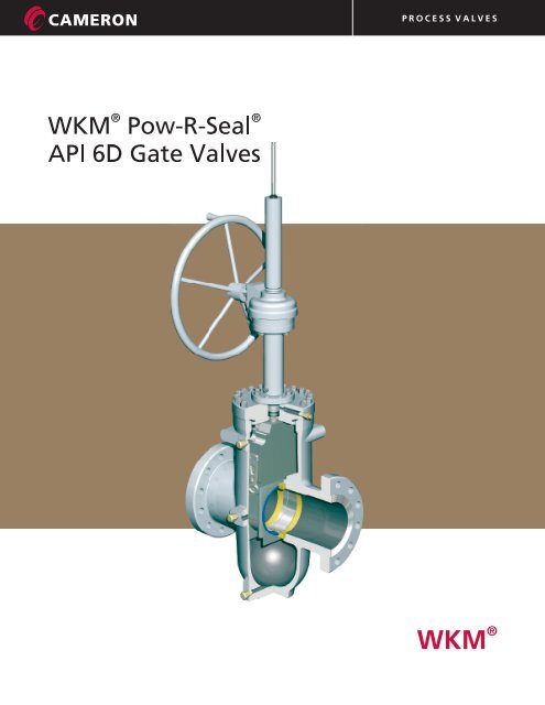
P R O C E S S V A L V E S®WKM
P R O C E S S V A L V E STABLE OF CONTENTSWKM <strong>Pow</strong>-R-<strong>Seal</strong> GATE VALVESDesign 2Operating Principles 4Features 6DIMENSIONAL DATAModel M2 in. - 4 in. (50 mm - 100 mm) 9Model E1C6 in. - 12 in. (150 mm - 300 mm) 10Model E1C14 in. - 24 in. (350 mm - 600 mm) 11GEAR SIZINGModel M2 in. - 4 in. (50 mm - 100 mm)Model E1C6 in. -24 in. (150 mm - 300 mm) 12Topworks Data 13Flow Coefficients (C ) 15VFlow Coefficients (K ) 16VPartial Open Flow Characteristics (CVor K V) 17Pressure Temperature Ratings 18Trim Chart 20Applications (Pictures) 22TRADEMARK INFORMATION 24® CT-WKM-POWRSEAL/GATEWKM11/08 ION-3M 1
P R O C E S S V A L V E SWKM POW-R-SEAL API 6D THROUGH-CONDUIT GATE VALVESOPERATING PRINCIPLESThe <strong>Pow</strong>-R-<strong>Seal</strong> gate valve is a premium through conduitexpanding gate valve. The parallel expanding gate designprovides a tight mechanical seal which is normallyunaffected by pressure variations. Each seat contains aplastic face seal. The seats are press fit into the body toaffect a metal-to-metal body-seat seal. A non-metallic seatrear seal is also provided. All metal seats are available forspecial trims.The full bore design has the same pressure drop as anequivalent length of pipe and allows passage of all typesof scrapers (pigs).The body center section is cast as a single piece toprovide the necessary strength to resist pipeline bendingmoments.The gate-segment assembly consists of Gate, Segmentand Gate centralizer (two assemblies). The Gate-segmentassembly is smaller than the space between the seatsallowing free movement in the mid-travel position.In the CLOSED position, the segment stops moving when itcontacts the stop. Continued stem movement causes thegate to slide down the top angles, expanding the gatesegmentoutward against both seats. In the OPENposition, the segment stops moving when it contacts thestop.Continued stem movement causes the gate to slide up thebottom angles, again expanding the gate-segment againstboth seats. Flow is isolated from the valve body. The gatecentralizer allows the gate-segment to move freely andwedge only in the full open or full closed position.<strong>Pow</strong>-R-<strong>Seal</strong> valves do not depend on lubrication for a sealin normal operation. However, lubricants/sealants can beinjected to promote smooth operation*. Seat sealants canalso be injected to affect a seal in an emergency shouldthe seats become damaged due to foreign matter.The stem is sealed by the SLS system. This seal ishydrocarbon fugitive emissions tested and hasdemonstrated seal-ability not to exceed 500 ppm leakage.It consists of a single Spring Loaded Lip seal, a lanternring, a chevron ring and appropriate adapters. The Single* Some high temperature valves do not have the seatinjection feature.Spring Loaded Lip seal contains four (4) separatedsealing bands to promote reliability. The stem seal iscompletely contained in the bonnet. The stem iscentered by bushings and the lower pedestal acts as astem scraper. The seal works without a plastic injectable.In an emergency, plastic packing can be injected intothe packing box to affect a temporary seal while thevalve is under pressure.The bonnet seal is made by a flat metal gasket in the6 in. - 12 in. (150 mm - 300 mm) size range.Bonnet seals for sizes 14 in. - 24 in. (350 mm - 600 mm)are made with an O-ring seal. High temperature valvesuse a spiral wound metal gasket with a non-asbestosfiller.<strong>Pow</strong>-R-<strong>Seal</strong> valves are repairable in-line.<strong>Pow</strong>-R-<strong>Seal</strong> gate valves meet the requirements of API 6D.The valve stroke is established by manufacturingtolerances and cannot get out of adjustment.<strong>Pow</strong>-R-<strong>Seal</strong> gate valves are available with hand wheeloperators (some sizes), bevel gear operators, or lessgearing (bare stem). Electric motor operators from avariety of suppliers can be offered.Operator mounting is simplified as yoke tube upperflanges are in compliance with MSS-SP-102. Yoke tubeflanges in compliance with ISO 5210 are available.<strong>Pow</strong>-R-<strong>Seal</strong> gate valves are supplied with indicators asa standard for Handwheel and Bevel Gear Operatedvalves. Handwheel Operated valves have marks onthe indicator rods which show when the valve is inthe full open or closed position.<strong>Pow</strong>-R-<strong>Seal</strong> gate valves are available with Lubrication/Packing/Drain extensions.<strong>Pow</strong>-R-<strong>Seal</strong> gate valves are also available withStem/Yoke tube extensions.<strong>Pow</strong>-R-<strong>Seal</strong> gate valves are available with a variety ofcoatings including Coal Tar Epoxy for buried service,2-3 part coating systems for marine environments,Inorganic Zinc Rich Epoxy, etc.4®WKM CT-WKM-POWRSEAL/GATE11/08 ION-3M
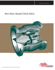
P R O C E S S V A L V E SWKM POW-R-SEAL API 6D THROUGH-CONDUIT GATE VALVESOPERATIONWKM <strong>Pow</strong>-R-<strong>Seal</strong> is the ultimate choice for Full Port,Through Conduit, Positive Shut-Off gate valves.60 years of Worldwide service in oil, gas, chemicals,water, slurry and multi-products has confirmedthe <strong>Pow</strong>-R-<strong>Seal</strong> as the most trusted gate valve,where safety and reliability of sealing are critical.The parallel expanding gate design provides a tightmechanical seal which is normally unaffected byvibrations or pressure variations.The rigid, cast steel body resists pipeline bendingmoments, which could affect seat sealing in othervalves.PTFE seals on both faces of the valve assure droptight sealing, while metal-metal contact betweenthe seals and gate mechanism provides tight shut-off.All-metal seals are also available for service to1000°F (538°C), where leakage rates comply withAPI 6D/ISO 5208.SEALED CLOSEDIn the fully closed position thesegment has engaged with anend-stop and the gate is wedgeddownward, expanding the segmentand gate so that they form a tightmechanical closure against theupstream and downstream seats.Venting the body cavity willprovide total, tight shut off.MID-TRAVELDuring travel towards Open,the gate slides across the wedgeangle of the segment, collapsingthe assembly so that it travelsfreely between the seal faces.The patented Leverlock gatecentralizer holds the mechanismin the neutral position until sealexpansion is required.FULLY OPENWhen the bore in the segment isaligned with the conduit bore, anend-stop prevents further traveland the gate slides across thewedge angle, expanding the gateand the segment, isolating theflow from the body.The preferred flow directionassures easier operation.LEVERLOCK MECHANISMThe lever arm is held parallel to the gate faces by the skirt plates,while the assembly is moving through its stroke.Near end-of-travel, the skirt allows the lever to tilt.The gate and segment slide against their angled faces, creatingthe expanding seal action.In their final position, the gate and segment are mechanicallysecured in place.The skirt plates are guide rails, at the sides of the gate.The skirts align the gate and segments with the seats.®WKM CT-WKM-POWRSEAL/GATE11/07 ION-3M5
P R O C E S S V A L V E SWKM POW-R-SEAL API 6D THROUGH-CONDUIT GATE VALVESFEATURESThrough-conduit design:smooth bore, minimumpressure drop, protectedseat facesThe <strong>Pow</strong>-R-<strong>Seal</strong> valve’s smooth,continuous bore minimizes turbulence.In full bore valves pressure drop is nomore than through an equal length ofthe same size pipe. Seat faces areoutside the flow stream and thusprotected from contact with the ladingwhether the valve is open or closed.The <strong>Pow</strong>-R-<strong>Seal</strong>’s full round bore makesit possible to run pigs, scrapers or hottap cutters through the valves withoutdanger of damaging the valve, lodgingthe scraper, or jamming it with metalcutting.Double-<strong>Seal</strong>ingReplaceable SeatsSeats can be removed andreplaced while the valve is inthe line. Seats are providedwith PTFE inserts and thusaffect a double seal - an initialTFE-to-metal seal in additionto a metal-to-metal seal - bothupstream and downstream.This feature does not apply tohigh temperature valves.Gate andSegment/Stems<strong>Pow</strong>-R-<strong>Seal</strong> gates andstems are Nickel Plated.HF-6 overlay is availableon request for thegate/segment and seatsealing surfaces.On-Line Overhaul<strong>Pow</strong>-R-<strong>Seal</strong> valves can be overhauledright on the line. Gate, seats andother internal parts can be removedand replaced by a trainedserviceman without excessiveshutdown time.Gate Centralizer<strong>Pow</strong>-R-<strong>Seal</strong>s of 6 inch andlarger sizes feature the®leverlock gate centralizerwhich retains the gatesegmentassembly in aneutral position duringopening and closing travelbut permits expansion ofthe assembly at the propermoment for seating, inopen or closed position.ExtensionsFor valves which are tobe buried, operated froma catwalk, or otherwisedifficult to reach, stemand body fittingextensions can besupplied in virtually anydesired length in 6 inchincrements from theminimum extensionlength that canbe furnished.Extensionscome asoriginalequipmentor can befield-installedon valvesalready inservice.6®WKM CT-WKM-POWRSEAL/GATE11/08 ION-3M
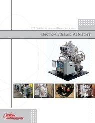
P R O C E S S V A L V E SWKM POW-R-SEAL API 6D THROUGH-CONDUIT GATE VALVESTHERMAL RELIEF SYSTEMOperations:Because of the split gate design, it is possible forexcess body pressure to develop in the body cavitiesof closed valves. This usually results from heating inthe valves in liquid service. A thermal body cavityrelief system is provided to relieve this excess bodypressure. Thermal relief systems which direct excessbody pressure to the upstream conduit are standard.This system consists of two (2) needle valves, a checkvalve, tubing and two (2) fittings.Body pressure greater than the segment conduitpressure causes the check valve to unseat and relieveexcess pressure to the upstream conduit.The needle valve must be kept open while the valveis in service. These needle valves can be used toisolate the line pressure to service the relief system,as needed. This illustrates the standard body reliefsystem. Custom body relief systems may be availableat extra cost.TYPICAL THERMAL BODY CAVITY RELIEF ARRANGEMENT541231ITEM PART QTY1 Needle Valve 22 Female Tubing Connector 13 Check Valve 14 Male Tubing Connector 15 Tubing 1Tag (Not Shown) 2Wire (Not Shown) 1NOTES: (a) These items are on the lettered side of the valve.(b) Special Thermal Relief Systems are available upon request.®WKMCT-WKM-POWRSEAL/GATE11/08 ION-3M7
P R O C E S S V A L V E SWKM POW-R-SEAL API 6D THROUGH-CONDUIT GATE VALVESSUMMARY OF WKM MODEL E-1C POW-R-SEAL GATE VALVE FEATURES1. THROUGH CONDUIT PARALLEL EXPANDING GATE VALVEabProvides a tight mechanically activated seal.Full bore design minimizes pressure drop and allows passage of all types of scrapers (pigs).2. FUGITIVE EMISSIONS TESTED SLS STEM SEAL*abcdefgStem <strong>Seal</strong> is completely contained in the bonnet.Stem is centralized by bearings.Fugitive emissions tested.<strong>Seal</strong> is self adjusting and does not depend on plastic packing.PTFE compound resists virtually all ladings.Pedestal supports the seal and acts as a stem scraper.6 in. - 24 in. (150 mm - 600 mm) 300-900 Class valves are fire tested to API 6FA (3rd Edition).3. INTERFERENCE FIT SEATSabcdefgBlock and Bleed per API 6DSimple design is resistant to dirty service.Insert initiates the seal and helps clean the gate.**<strong>Seal</strong>s are compatible with virtually all ladings.Seats may be lubricated to promote long life, minimize operating torques, or effect a seal in anemergency.6 in. - 12 in. (150 mm - 300 mm) 300-900 Class valves are fire tested to API 6FA (3rd Edition).14 in. - 24 in. (350 mm - 600 mm) 600-900 Class valves are fire tested to API 6FA (3rd Edition).4. BOLTED BONNET-VALVE IS IN-LINE REPAIRABLEBonnet seal resists virtually all ladings.5. YOKE TUBE UPPER FLANGE CONFORMS TO ISO 5210(6 in. - 12 in. (150 mm - 300 mm) 300 - 900) and MSS-SP-102Simplifies operator mounting.6. SINGLE PIECE CAST BODY CENTER SECTIONa Provides the necessary strength to resist pipeline bending.b Smooth shape minimizes stress concentrations.c Made from pressure vessel quality steel.7. VALVE STROKE IS ESTABLISHED BY MANUFACTURING TOLERANCESCannot get out of adjustment.8. VALVES AVAILABLE WITH HAND WHEEL OPERATORS***, BEVEL GEAR OPERATORS,OR LESS GEARING (BARE STEM)Also available with electric motor operators from a variety of suppliers.9. SEVERAL TYPES OF BODY CAVITY THERMAL RELIEF SYSTEMS ARE AVAILABLE10. LUBE, PACKING AND DRAIN EXTENSIONS ARE AVAILABLE11. STEM/YOKE EXTENSIONS ARE AVAILABLE12. VARIETY OF AVAILABLE PAINTS/COATINGS* Does not apply to high temperature valves.** High Temperature valves do not have the insert.*** 6 in. (150 mm) through 10 in. (250 mm) 300-900 Class and 12 in. (300 mm) 300-600 Class only in selected sizes.8®WKM CT-WKM-POWRSEAL/GATE11/08 ION-3M
P R O C E S S V A L V E SWKM POW-R-SEAL API 6D THROUGH-CONDUIT GATE VALVESMODEL M2 in. - 4 in. (50 mm - 100 mm) HANDWHEEL OPERATEDHASME CLASSMAX.WP @ 100°F (38°C)600 1500 psi CWP2250 psi Test900 2250 psi CWP3375 psi Test1500 3750 psi CWP5625 psi TestGBFPRINCIPAL DIMENSIONSN = Number of turns of Handwheel to fully open or close valve.AASME CLASS 600Size in.Weight lb. (kg)(mm) A B F G H N FE WE F x W2 11 1/2 2 1/16 4 13/16 17 3/4 12 16 90 72 84(50) (292) (52) (122) (451) (305) 16 (41) (33) (38)3 14 3 3/16 6 15/16 23 7/8 12 20 180 144 155(80) (356) (81) (176) (606) (305) 20 (82) 1(65) (70)4 17 4 1/8 8 5/8 27 14 20 345 259 245(100) (432) (105) (219) (686) (356) 20 (156) (117) (111)ASME CLASS 9002 14 1/2 2 1/16 5 1/16 17 3/4 12 16 150 72 105(50) (368) (52) (129) (451) (305) 16 (68) (33) (48)3 15 3 3/16 7 5/16 23 7/8 12 20 265 193 247(80) (381) (81) (186) 2(606) (305) 20 (120) (88) (112)4 18 4 1/8 9 1/16 28 1/2 18 20 515 390 417(100) (457) (105) (230) (724) (457) 20 (234) (177) (189)ASME CLASS 15002 14 1/2 2 1/16 5 1/16 17 3/4 12 16 150 72 105(50) (368) (52) (129) (451) (305) 16 (68) (33) (48)3 18 1/2 3 3/16 7 5/16 23 7/8 12 20 295 215 242(80) (470) 3(81) (186) (606) (305) 20 (134) (98) (110)4 21 1/2 4 1/8 9 1/16 28 1/2 18 20 530 403 325(100) (546) (105) (230) (724) (457) 20 (240) (183) (147)Flange dimensions conform to American National Standards Institute Standard B16.5, 1981.Information on power-actuated and other types of valves available on application.®WKM CT-WKM-POWRSEAL/GATE11/08 ION-3M9
P R O C E S S V A L V E SWKM POW-R-SEAL API 6D THROUGH-CONDUIT GATE VALVESMODEL E1C6 in. - 12 in. (150 mm - 300 mm) HANDWHEEL OPERATEDAND BEVEL GEAR OPERATEDHASME CLASSMAX.WP @ 100°F (38°C)300 750 psi CWP1125 psi Test600 1500 psi CWP2250 psi TestGKG900 2250 psi CWP3375 psi TestPRINCIPAL DIMENSIONSN = Number of turns of Handwheel orBevel Gear Operator Handwheel tofully open or close valve.BFBFAAASME CLASS 300Size in. A B F G G H K N N Weight lb. (kg) HWO Weight lb. (kg) BGO(mm) (HWO BGO HWO BGO FE WE F x W FE WE F x W6 15 7/8 6 12 1/2 45 1/4 46 1/4 24 30 11/16 29 114 472 397 400 500 445 470(150) (403) (152) (318) (1149) (1175) (610) (779) 29 114 (214) (180) (181) (227) (202) (213)8 16 1/2 8 16 57 1/4 56 1/4 24 36 11/16 37 146 853 751 805 903 845 895(200) (419) (203) (406) (1454) (1429) (610) (932) 37 146 (387) (341) (365) (410) (383) (406)10 18 10 20 63 1/4 64 1/4 24 44 11/16 45 180 1345 1200 1273 1475 1380 1448(250) (457) (254) (508) (1607) (1632) (610) (1135) 45 180 (610) (544) (577) (669) (626) (657)12* 30 12 22 3/4 73 3/8 74 5/8 30 51 11/16 40 239 - - - 1950 1670 1880(300) (762) (305) (578) (1864) (1895) (762) (1313) 40 239 - - - (885) (757) (853)ASME CLASS 6006 22 6 12 5/8 45 1/4 46 1/4 24 30 11/16 29 114 595 495 545 695 575 635(150) (559) (152) (321) (1149) (1175) (610) (779) 29 114 (270) (225) (247) (315) (261) (288)8 26 8 15 1/2 57 1/4 56 1/4 24 36 11/16 37 146 1028 730 865 1075 895 990(200) (660) (203) (394) (1454) (1429) (610) (932) 37 146 (466) (331) (392) (488) (406) (449)10 31 10 19 3/4 64 7/8 66 1/8 24 45 3/16 34 203 1735 1370 1505 1895 1585 1835(250) (787) (254) (502) (1648) (1680) (610) (1148) 34 203 (787) (621) (683) (860) (719) (832)12 33 12 23 73 3/8 74 5/8 30 51 11/16 40 239 2525 2360 2480 3030 2250 2360(300) (838) (305) (584) (1864) (1895) (762) (1313) 40 239 (1145) (1070) (1125) (1374) (1021) (1070)ASME CLASS 9006 24 6 12 7/8 45 1/4 46 1/4 24 30 3/4 29 114 743 577 625 805 565 680(150) (610) (152) (327) (1149) (1175) (610) (781) 29 114 (337) (262) (283) (365) (256) (308)8 29 8 15 3/4 57 1/4 56 1/4 24 36 3/4 37 146 1272 1040 1180 1329 1180 1238(200) (737) (203) (400) (1454) (1429) (610) (933) 37 146 (577) (472) (535) (603) (535) (562)10 33 10 20 1/8 64 7/8 66 1/8 30 45 1/4 34 203 2250 1930 2085 2315 1875 2185(250) (838) (254) (511) (1648) (1680) (762) (1149) 34 203 (1021) (875) (946) (1050) (850) (991)12 38 12 23 1/2 - 73 3/4 30 56 5/8 40 318 3392 2725 2860 3600 2880 3276(300) (965) (305) (597) - (1873) (762) (1438) 40 318 (1539) (1236) (1297) (1633) (1306) (1486)* 12 in. (300 mm) 300 Class valves have 400 class End-to-End dimensions.®10 WKM CT-WKM-POWRSEAL/GATE11/08 ION-3M
P R O C E S S V A L V E SWKM POW-R-SEAL API 6D THROUGH-CONDUIT GATE VALVESMODEL E1C14 in. - 24 in. (350 mm - 600 mm)BEVEL GEAR OPERATEDASME CLASSMAX.WP @ 100°F (38°C)300 750 psi CWP1125 psi Test600 1500 psi CWP2250 psi Test900 2250 psi CWP3375 psi TestKGBPRINCIPAL DIMENSIONSN = Number of turns of Bevel Gear Operator Handwheel to fully open or close valve.ASME CLASS 300Size in.Weight lb. (kg)(mm) A B F G K N FE WE F x W14* 30 13 1/4 25 1/4 65 7/8 53 177 2632 2230 2500(350) (762) (337) (641) (1673) (1346) 177 (1194) (1012) (1134)16 33 15 1/4 28 1/8 83 9/16 58 3/8 167 3450 3015 3310(400) (838) (387) (714) (2122) (1483) 167 (1565) (1368) (1501)18 36 17 1/4 31 86 13/16 65 5/16 190 4650 4260 4375(450) (914) (438) (787) (2205) (1659) 190 (2109) (1932) (1984)20 39 19 1/4 35 1/4 106 1/4 73 7/8 211 6248 5780 6000(500) (991) (489) (895) (2699) (1876) 211 (2834) (2622) (2722)24* 45 23 1/4 42 115 3/4 86 3/8 253 10678 9550 10240(600) (1143) (591) (1067) (2940) (2194) 253 (4843) (4332) (4645)ASME CLASS 60014 35 13 1/4 25 9/16 69 3/4 53 1/2 177 3240 2931 3000(350) (889) (337) (649) (1772) (1359) 177 (1470) (1329) (1361)16 39 15 1/4 28 1/8 81 1/8 61 1/4 167 4420 3950 4160(400) (991) (387) (714) (2061) (1556) 167 (2005) (1792) (1887)18 43 17 1/4 31 5/8 86 1/2 66 5/8 190 5705 5115 5200(450) (1092) (438) (803) (2197) (1692) 190 (2588) (2320) (2359)20 47 19 1/4 36 98 1/8 73 7/8 211 7595 7115 6605(500) (1194) (489) (914) (2492) (1876) 211 (3445) (3227) (2996)24 55 23 1/4 42 1/4 113 1/2 87 7/8 253 12994 11380 12730(600) (1397) (591) (1073) (2883) (2232) 253 (5894) (5162) (5774)ASME CLASS 90014 40 1/2 12 3/4 26 1/8 69 3/4 53 1/2 - 5200 4902 4902(350) (1029) (324) (664) (1772) (1359) - (2359) (2224) (2224)16 44 1/2 14 3/4 30 1/4 81 1/8 66 5/8 174 7346 6435 6956(400) (1130) (375) (768) (2061) (1692) 174 (3332) (2919) (3155)18 48 16 3/4 33 92 - - 11814 10226 11020(450) (1219) (425) (838) (2337) - - (5359) (4638) (4999)20 52 18 5/8 36 103 - - 15581 14265 14866(500) (1321) (473) (914) (2616) - - (7067) (6470) (6743)24 61 22 1/2 44 1/2 113 1/2 87 7/8 - 20467 18561 19887(600) (1549) (572) (1130) (2883) (2232) - (9284) (8419) (9021)* 14 in. & 24 in. (350 mm & 600 mm) 300 Class valves have 400 class End-to-End dimensions.AF®WKM CT-WKM-POWRSEAL/GATE11/08 ION-3M11
P R O C E S S V A L V E SWKM POW-R-SEAL API 6D THROUGH-CONDUIT GATE VALVESOPERATOR SIZING REQUIREMENTSMODEL M, 2 in. - 4 in. (50 mm - 100 mm) ASME CLASS 150-1500ASMEStem ThreadRecommended Recommended Block & Block & Maximum Maximum Total TurnsValve Working Operating Operating Bleed Bleed Allowable Allowable Stem toSize ASME Pressure Size Pitch Lead Thrust Torque Thrust Torque Thrust Torque Travel Openin. (mm) Class (psig) in. in. in. (lbf) (ft-lbf) (lbf) (ft-lbf) (lbf) (ft-lbf) in. (mm) Valve2 (50) 150 290 0.875 0.167 0.167 457 3 535 4 12597 93 2.63 (67) 15.82 (50) 300 750 0.875 0.167 0.167 1183 9 1383 10 12597 93 2.63 (67) 15.82 (50) 600 1500 0.875 0.167 0.167 2366 17 2766 20 12597 93 2.63 (67) 15.82 (50) 900 2250 0.875 0.167 0.167 3549 26 4149 30 12597 93 2.63 (67) 15.82 (50) 1500 3750 0.875 0.167 0.167 5914 43 6915 51 12597 93 2.63 (67) 15.83 (80) 150 290 1.000 0.200 0.200 803 7 1115 9 16027 136 4.03 (102) 20.23 (80) 300 750 1.000 0.200 0.200 2078 18 2884 25 16027 136 4.03 (102) 20.23 (80) 600 1500 1.000 0.200 0.200 4155 35 5769 49 16027 136 4.03 (102) 20.23 (80) 900 2250 1.000 0.200 0.200 6233 53 8653 74 16027 136 4.03 (102) 20.23 (80) 1500 3750 1.000 0.200 0.200 10388 88 14422 123 16027 136 4.03 (102) 20.24 (100) 150 290 1.250 0.250 0.250 1327 14 1783 19 25442 271 4.88 (124) 19.54 (100) 300 750 1.250 0.250 0.250 3432 37 4610 49 25442 271 4.88 (124) 19.54 (100) 600 1500 1.250 0.250 0.250 6864 73 9221 98 25442 271 4.88 (124) 19.54 (100) 900 2250 1.250 0.250 0.250 10297 110 13831 147 25442 271 4.88 (124) 19.54 (100) 1500 3750 1.250 0.250 0.250 17161 183 23052 245 25442 271 4.88 (124) 19.5MODEL E-1C, 6 in. - 24 in. (150 mm - 600 mm) ASME CLASS 300 THROUGH 9006 (150) 300 750 1.50 0.250 0.250 6626 82 8179 101 21711 267 7.19 (183) 296 (150) 600 1500 1.50 0.250 0.250 13252 163 16358 201 21711 267 7.19 (183) 296 (150) 900 2250 1.50 0.250 0.250 19878 245 24538 302 33158 408 7.19 (183) 298 (200) 300 750 1.75 0.250 0.250 10705 149 12626 176 23678 329 9.12 (232) 368 (200) 600 1500 1.75 0.250 0.250 21410 298 25253 351 26577 370 9.12 (232) 368 (200) 900 2250 1.75 0.250 0.250 32115 447 37879 527 42377 590 9.12 (232) 3610 (250) 300 750 2.25 0.333 0.333 16462 296 19385 349 36141 651 11.31 (287) 3410 (250) 600 1500 2.25 0.333 0.333 32924 593 38771 698 46433 836 11.31 (287) 3410 (250) 900 2250 2.25 0.333 0.333 49386 889 58156 1047 76635 1380 11.31 (287) 3412 (300) 300 750 2.25 0.333 0.333 21911 395 27588 497 52472 945 13.38 (340) 4012 (300) 600 1500 2.25 0.333 0.333 43822 789 55175 994 64733 1166 13.38 (340) 4012 (300) 900 2250 2.25 0.333 0.333 65732 1184 82763 1490 84560 1523 13.38 (340) 4014 (350) 300 750 2.00 0.250 0.500 25138 477 32355 614 78209 1485 14.88 (378)14 (350) 600 1500 2.00 0.250 0.500 50276 955 64709 1229 78209 1485 14.88 (378)14 (350) 900 2250 2.25 0.333 0.333 72608 1308 101857 1835 110039 1982 14.88 (378)16 (400) 300 750 2.50 0.400 0.800 33517 868 39174 1015 108946 2822 16.88 (429)16 (400) 600 1500 2.50 0.400 0.800 67035 1736 78348 2029 108946 2822 16.88 (429)16 (400) 900 2250 2.75 0.400 0.800 97481 2681 146275 4022 162485 4468 17.38 (441)18 (450) 300 750 2.50 0.400 0.800 41440 1073 48846 1265 113120 2930 18.94 (481)18 (450) 600 1500 2.50 0.400 0.800 82881 2147 97691 2530 113120 2930 18.94 (481)18 (450) 900 2250 3.00 0.400 0.400 123194 2901 173424 4084 185236 4362 19.88 (505)20 (500) 300 750 2.75 0.400 0.800 51116 1406 60201 1655 113120 3111 21.12 (536)20 (500) 600 1500 2.75 0.400 0.800 102231 2811 120401 3311 129553 3562 21.12 (536)20 (500) 900 2250 3.25 0.400 0.800 150254 3780 248075 6241 262230 6597 -22 (550) 300 No Design22 (550) 600 1500 3.00 0.400 0.800 123768 3601 149487 4349 118661 3453 23.25 (591)22 (550) 900 No Design24 (600) 300 750 3.00 0.400 0.800 72557 2111 91789 2671 113120 3291 25.25 (641)24 (600) 600 1500 3.00 0.400 0.800 145115 4222 183577 5341 203038 5908 25.25 (641)24 (600) 900 2250 3.75 0.400 0.800 214524 7273 356572 12089 351789 11927 -NOTE: 1. Use RECOMMENDED OPERATING THRUST and TORQUES for sizing bevel gear operators.2. Use BLOCK & BLEED THRUSTS and TORQUES for sizing <strong>Pow</strong>er operators (Electric, gas, hydraulic, etc.).3. MAXIMUM OPERATING THRUST and TORQUES are the maximum allowable for the valve.®12 WKM CT-WKM-POWRSEAL/GATE11/08 ION-3M
P R O C E S S V A L V E SWKM POW-R-SEAL API 6D THROUGH-CONDUIT GATE VALVESOPERATOR INTERFACE DIMENSIONSTOPWORKSOperator Interface comply with ISO 5210 (6 in. to 12 in. (150 mm to 300 mm) only) and MSS-SP-102.An adapter ring is provided on 6 in. to 12 in. (150 mm to 300 mm) bare stem/less gearing valves tocomply with ISO 5210 or MSS-SP-1021/4”-18NPTDTOTALSTEMTRAVELEEND OFSTEM THD.DIAFMINIMUMFULL THD.AØ HJ ØL ØBTOP OFSTEMCLOSEDCTOP OFSTEMOPENM ØPNK = NUMBER &SIZE OF HOLESGTO CENTERLINEOF VALVEBORESee page 14 for Operator Interface Dimensions.®WKM CT-WKM-POWRSEAL/GATE11/08 ION-3M13
P R O C E S S V A L V E SWKM POW-R-SEAL API 6D THROUGH-CONDUIT GATE VALVESOPERATOR INTERFACE DIMENSIONSTOPWORKSSizein.ClassMSSA-NA-2G-L.H. B C D E F G H J K L M N PFlg6 309C FA14 1 1/2 - .250P - .250L 8.31 15.50 7.19 16.44 16.06 26.88 7.00 5.50 4 - 0.69 3.955 2.50 1.03 0.178Single Lead Thread 3.9458 3-9C FA14 1 3/4 - .250P - .250L 8.44 17.56 9.12 18.94 18.56 32.00 7.00 5.50 4 - 0.69 3.955 2.50 1.03 0.178Single Lead Thread 3.94510 3-9C FA16 2.25 - .333P - .333L 9.38 20.69 11.31 24.38 24.00 42.13 8.38 6.50 4 - 0.81 5.230 3.12 1.50 0.230Single Lead Thread 5.220 3.75 2.7512 3-6C FA16 2.25 - .333P - .333L 11.50 24.88 13.38 26.06 25.69 45.44 8.38 6.50 4 - 0.81 5.230 3.12 1.50 0.230Single Lead Thread 5.2209C FA16 2.25 - .333P - .333L 11.34 24.75 13.38 26.06 25.69 45.56 8.38 6.50 4 - 0.81 5.230 3.12 1.50 0.230Single Lead Thread 5.22014 3-6C FA16 2 - .250P - .500L 9.56 24.38 14.81 27.50 26.88 50.44 8.38 6.50 4 - 0.81 5.230 3.12 1.50 0.230Double Lead Thread 5.22016 3-6C FA25 2 1/2 - .400P - .800L 10.19 27.06 16.88 31.19 30.56 56.50 11.50 10.00 8 - 0.69 6.020 3.75 2.00 0.230Double Lead Thread 6.01018 3-6C FA25 2 1/2 - .400P - .800L 9.31 28.25 18.94 32.69 32.19 63.88 11.50 10.00 8 - 0.69 6.020 3.75 2.00 0.230Double Lead Thread 6.01020 3C FA25 2 3/4 - .400P - .800L 11.50 32.62 21.12 37.00 36.44 70.31 11.50 10.00 8 - 0.69 6.020 3.75 2.00 0.230Double Lead Thread 6.0106C FA30 2 3/4 - .400P - .800L 11.50 32.62 21.12 37.00 36.44 70.31 13.62 11.75 8 - 0.81 7.020 3.75 2.75 0.230Double Lead Thread 7.01024 3C FA25 3 - .400P - .800L 12.37 37.62 25.25 43.06 42.56 85.19 11.50 10.00 8 - 0.69 6.020 3.75 2.00 0.230Double Lead Thread 6.0106C FA35 3 - .400P - .800L 12.37 37.62 25.25 43.06 42.56 85.19 16.12 14.00 8 - 1.12 8.520 4.00 3.25 0.230Double Lead Thread 8.510SizemmClassMSSA-NA-2G-L.H. B C D E F G H J K L M N PFlg150 309C FA14 38.1 - .250P - .250L 211 394 183 418 408 683 178 140 4 - 17.53 100.46 63.5 26.16 4.52Single Lead Thread 100.20200 3-9C FA14 44.45 - .250P - .250L 214 446 232 481 471 813 178 140 4 - 17.53 100.46 63.5 26.16 4.52Single Lead Thread 100.20250 3-9C FA16 57.15 - .333P - .333L 238 526 287 619 610 1070 213 165 4 - 20.57 132.84 79.25 38.1 5.84Single Lead Thread 132.59 95.25 69.85300 3-6C FA16 57.15 - .333P - .333L 292 632 340 662 653 1154 213 165 4 - 20.57 132.84 79.25 38.1 5.84Single Lead Thread 132.599C FA16 57.15 - .333P - .333L 288 629 340 662 653 1157 213 165 4 - 20.57 132.84 79.25 38.1 5.84Single Lead Thread 132.59350 3-6C FA16 50.8 - .250P - .500L 243 619 376 699 683 1281 213 165 4 - 20.57 132.84 79.25 38.1 5.84Double Lead Thread 132.59400 3-6C FA25 63.5 - .400P - .800L 259 687 429 792 776 1435 292 254 8 - 17.53 152.91 95.25 50.8 5.84Double Lead Thread 152.65450 3-6C FA25 63.5 - .400P - .800L 9.31 718 481 830 818 1623 292 254 8 - 17.53 152.91 95.25 50.8 5.84Double Lead Thread 152.65500 3C FA25 69.85 - .400P - .800L 292 829 536 940 926 1786 292 254 8 - 17.53 152.91 95.25 50.8 5.84Double Lead Thread 152.656C FA30 69.85 - .400P - .800L 292 829 536 940 926 1786 346 298 8 - 20.57 178.31 95.25 69.85 5.84Double Lead Thread 178.10600 3C FA25 76.2 - .400P - .800L 314 956 641 1094 1081 2164 292 254 8 - 17.53 152.91 95.25 50.8 5.84Double Lead Thread 152.656C FA35 76.2 - .400P - .800L 314 956 641 1094 1081 2164 409 356 8 - 28.45 216.41 101.6 82.55 5.84Double Lead Thread 216.15®14 WKM CT-WKM-POWRSEAL/GATE11/08 ION-3M
P R O C E S S V A L V E SWKM POW-R-SEAL API 6D THROUGH-CONDUIT GATE VALVESFLOW COEFFICIENTS (C ) VThe following chart outlines the C for through conduit gate valves having end-to-end dimensionsVand bore diameters in compliance with API 6D.*Since C is a calculated number, the actual value may vary.VValve Size in. 300 400 600 900 1500 25002 432 378 378 337 337 2183 x 2 - 165 165 203 239 -2 1/2 - 682 682 558 558 3053 1155 1053 1109 1072 966 4744 x 3 - 534 529 597 677 6244 2176 1925 1944 1890 1730 7256 x 4 - 886 944 943 1231 -6 5300 4860 4577 4383 3622 25108 x 6 2499 - 3240 3588 2137 -8 11054 9345 8886 8416 6879 522710 x 8 5218 - 5036 7975 4859 -12 x 8 3302 - 3892 - - -10 18856 15771 14533 14087 11283 831312 (Note 1) 228980 23834 22729 21025 16843 1228212 x 10 - - 12799 7299 - -14 (Note 1) 30883 29921 28837 23846 20336 -16 x 14 - - 21096 - - -16 42224 41022 39144 33358 27548 2139620 x 16 - 15761 - - - -18 55740 54277 51368 45004 - -20 70386 68680 64559 56871 - -22 86869 85422 80279 - - -24 (Note 1) 106835 103504 97240 84836 - -26 123222 120829 114905 - - -28 144355 142391 135267 - - -30 170229 163776 157401 133706 - -36 245362 236147 224424 - - -* As Applicable.Notes: 1. 300 Class valves have 400 Class end-to-ends in these size <strong>Pow</strong>-R-<strong>Seal</strong> designs.Use the 400 Class CV.®WKM CT-WKM-POWRSEAL/GATE11/08 ION-3M15
P R O C E S S V A L V E SWKM POW-R-SEAL API 6D THROUGH-CONDUIT GATE VALVESFLOW COEFFICIENTS (K ) VThe following chart outlines the K for through conduit gate valves having end-to-end dimensionsVand bore diameters in compliance with API 6D.*Since K is a calculated number, the actual value may vary.VValve Size in. 300 400 600 900 1500 25002 373 327 327 291 291 1883 x 2 - 142 145 175 207 -2 1/2 - 590 590 483 483 2643 999 911 959 927 835 4104 x 3 - 462 458 516 585 5404 1882 1665 1682 1635 1496 6276 x 4 - 766 817 816 1065 -6 4585 4204 3959 3792 3133 21728 x 6 2162 - 2803 3103 1849 -8 9562 8084 7687 7280 5951 452210 x 8 4514 - 4356 6898 4204 -12 x 8 2857 - 3367 - - -10 16312 13643 12572 12186 9761 719112 (Note 1) 25070 20617 19662 18188 14570 1062412 x 10 - - 11072 6314 - -14 (Note 1) 26715 25883 24945 20628 17591 -14 x 12 - - - - - -16 x 14 - - 18249 - - -16 36526 35486 33862 28856 23831 1850920 x 16 - 13634 - - - -18 48218 46953 44436 38930 - -20 60888 59412 55847 49196 - -22 75147 73894 69445 - - -24 (Note 1) 92417 89536 84117 73388 - -26 106593 104523 99399 - - -28 124874 123175 117013 - - -30 147257 141674 136160 115662 - -40 x 30 - - - 6046436 212251 204279 194138 - - -42 x 36 70357 - - - - -40 266697 265814 265814 - - -42 - 302576 293854 - - -48 - - 408871 - - -* As Applicable.Note: 1. 300 Class valves have 400 Class end-to-ends in these size <strong>Pow</strong>-R-<strong>Seal</strong> designs.Use the 400 Class KV.®16 WKM CT-WKM-POWRSEAL/GATE11/08 ION-3M
P R O C E S S V A L V E SWKM POW-R-SEAL API 6D THROUGH-CONDUIT GATE VALVESPRESSURE TEMPERATURE RATINGS WITH STANDARD WCC MATERIALTemperatureWorking Pressure by Class,psig°C °F 150 300 400 600 900 1500-29°C to 38°C -20°F to 100°F 290 750 1000 1500 2250 375093°C 200°F 260 750 1000 1500 2250 3750149°C 300°F 230 730 970 1455 2185 3640204°C 400°F 200 705 940 1410 2115 3530260°C 500°F 170 665 885 1330 1995 3325316°C 600°F 140 605 805 1210 1815 3025343 650°F 125 590 785 1175 1765 2940371°C 700°F 110 570 755 1135 1705 2840399°C 750°F 95 505 670 1010 1510 2520427°C 800°F 80 410 550 825 1235 2060REF.: API 6D, ASME B16.34TemperatureWorking Pressure by Class, bar°C °F 150 300 600 900 1500-29°C to 38°C -20°F to 100°F 19.8 51.7 103.4 155.1 258.650°C 122°F 19.5 51.7 103.4 155.1 258.6100°C 212°F 17.7 51.5 103.0 154.6 257.6150°C 302°F 15.8 50.2 100.3 150.5 250.8200°C 392°F 13.8 48.6 97.2 145.8 243.2250°C 482°F 12.1 46.3 97.2 139.0 231.8300°C 572°F 10.2 42.9 85.7 128.6 214.4325°C 617°F 9.3 41.4 82.6 124.0 206.6350°C 662°F 8.4 40.0 80.0 120.1 200.1375°C 707°F 7.4 37.8 75.7 113.5 189.2400°C 752°F 6.5 34.7 69.4 104.2 173.6425°C 797°F 5.5 28.8 57.5 86.3 143.8General Note:(a) Flanged End Valve ratings terminate at 538°C (1000°F).®18 WKMCT-WKM-POWRSEAL/GATE11/08 ION-3M
P R O C E S S V A L V E SWKM POW-R-SEAL API 6D THROUGH-CONDUIT GATE VALVESPRESSURE TEMPERATURE RATINGS WITH STANDARD WC6 MATERIALTemperatureWorking Pressure by Class, psig°C °F 150 300 600 900 1500-29°C to 38°C -20°F to 100°F 290 750 1,500 2,250 3,75093°C 200°F 260 750 1,500 2,250 3,750149°C 300°F 230 720 1,445 2,165 3,610204°C 400°F 200 695 1,385 2,080 3,465260°C 500°F 170 665 1,330 1,995 3,325316°C 600°F 140 605 1,210 1,815 3,025343°C 650°F 125 590 1,175 1,765 2,940371°C 700°F 110 570 1,135 1,705 2,840399°C 750°F 95 530 1,065 1,595 2,660427°C 800°F 80 510 1,015 1,460 2,540454°C 850°F 65 485 975 1,350 2,435482°C 900°F 50 450 900 955 2,245510°C 950°F 35 320 640 650 1,595538°C 1000°F 20 215 430 430 1,080TemperatureWorking Pressure by Class, bar°C °F 150 300 600 900 1500-29°C to 38°C -20°F to 100°F 19.8 51.7 103.4 155.1 258.650°C 122°F 19.5 51.7 103.4 155.1 258.6100°C 212°F 17.7 51.5 103.0 154.4 257.4150°C 302°F 15.8 49.7 99.5 149.2 248.7200°C 392°F 13.8 48.0 95.9 143.9 239.8250°C 482°F 12.1 46.3 92.7 139.0 231.8300°C 572°F 10.2 42.9 85.7 128.6 214.4325°C 617°F 9.3 41.4 82.6 124.0 206.6350°C 662°F 8.4 40.3 80.4 120.7 201.1375°C 707°F 7.4 38.9 77.6 116.5 194.1400°C 752°F 6.5 36.5 73.3 109.8 183.1425°C 797°F 5.5 35.2 70.0 105.1 175.1450°C 842°F 4.6 33.7 67.7 101.4 169.0475°C 887°F 3.7 31.7 63.4 95.1 158.2500°C 932°F 2.8 25.7 51.5 77.2 128.6538°C 1000°F 1.4 14.9 29.8 44.7 74.5General Note: (a) Flanged End Valve ratings terminate at 538°C (1000°F).®WKMCT-WKM-POWRSEAL/GATE11/08 ION-3M19
P R O C E S S V A L V E SWKM POW-R-SEAL API 6D THROUGH-CONDUIT GATE VALVESTRIMST-10 WATERFLOOD (UNINHIBITED)Carbon steel body/bonnet with wetted surface, ENP plated, internal parts of corrosiveresistant materials.Temperature ratings: -20°F to +250°F (-29°C to +121°C).T-11 MODEL M - 2 inch, 3 inch, 4 inch, ASME CLASS 600 -1500STANDARD TRIMFor non-corrosive aromatic service with concentration of MTBE to 100 percent.Temperature rating: -20°F to +250°F (-29°C to +121°C).T-24 SOUR GAS AND OIL (NACE MR0175)Primarily for sour gas and oil (NACE MR0175) where resistance to hydrogen sulfideembrittlement is required. Also suitable for other chemicals, products or hydrocarbonswhen H2S is present. May be used when CO 2 is present is smaller amounts than H2S.Temperature ratings: -20°F to +250°F (-29°C to +121°C).T-30 High TEMPERATURE -20°F TO +650°F (-29°C TO 343°C)For higher temperature service where the corrosion resistance and wire drawing resistanceof the stainless internals with stellite overlay are suitable.The limiting temperature is a function of the body material which follows the appropriatepressure rating table. (Ref. ASME Std. B16.34, 1977).The temperature limitations are -20°F to +650°F (-29°C to +343°C).T-31 High TEMPERATURE - UP TO +1000°F (+538°C)For service above 550°F (288°C). Has same qualifications as T-30, except metal-to-metalseating only is required for temperatures from +650°F to +1000°F (+343°C to +538°C).T-36 LOW TEMPERATURE - 50°F (-46°C) NACEFor essentially non-corrosive ladings, either liquid or gaseous.The pressure retaining components (body, bonnet and bolting) are of impact tested materials.Temperature ratings: -50°F to +250°F (-46°C to +121°C).T-37 LOW TEMPERATURE SOUR -50°F (-46°C) NACEPrimarily for sour gas and oil (NACE MR0175) where resistance to hydrogen sulfideembrittlement is required at -50°F (-46°C) service.The pressure retaining components (body, bonnet and bolting) are of impact tested materials.Also suitable for other chemicals, products or hydrocarbons when H S is present.2May be used when CO is present is smaller amounts than H S.2 2Temperature ratings: -50°F to +250°F (-46°C to +121°C).T-102 HIGH AROMATIC (TO 100% MTBE) 6 inch - 24 inch 300 - 900For non-corrosive aromatic service with concentration of MTBE to 100 percent.Temperature rating: -20°F to +250°F (-29°C to +121°C).Other Trims Available on Request.®20 WKMCT-WKM-POWRSEAL/GATE11/08 ION-3M
P R O C E S S V A L V E SWKM POW-R-SEAL API 6D THROUGH-CONDUIT GATE VALVESTRIM CHARTService Trim Body & Gate & Seat Stem Stem Bolting FittingsCode Bonnet Segment <strong>Seal</strong>Waterflood, T-10 WCC Carbon Steel 300- Carbon Steel, PTFE Low Alloy Alloy StainlessCorrosive Carbon Steel, 600, Low Alloy Nickel Plated Steel, Nickel Steel Steel-20°F to 250°F Nickel 900 PTFE Insert Plated NACE-29°C to 121°C Plated Nickel PlatedStandard T-11 WCC Carbon Steel, Carbon Steel, FKM Low Alloy Alloy Carbon-20°F to 250°F 2 - 4 in. Carbon Low Alloy Steel, Nickel Plated Viton Steel, Nickel Steel Steel-29°C to 121°C only Steel Nickel Plated PTFE Insert PlatedSour, Mildly T-24 WCC Carbon Steel 300- Carbon Steel, PTFE Low Alloy Alloy StainlessCorrosive 2 in. & Carbon 600, Low Alloy Nickel Plated Steel, Nickel Steel Steel-20°F to 250°F larger Steel 900 PTFE Insert Plated NACE-29°C to 121°CNickel PlatedHigh T-30 WCC CA6NM Carbon Steel, Flexible 400 Series Alloy StainlessTemperature Carbon Stainless Steel, HF-6 Hard Faced Graphite Stainless Steel Steel-20°F to 650°F Steel HF-6 Hard Faced Steel-29°C to 343°CHigh T-31 WC6 CA6NM A182 F11 Flexible 400 Series Alloy StainlessTemperature Carbon Stainless Steel, Carbon Steel, Graphite Stainless Steel Steel-20°F to 1000°F Steel HF-6 Hard Faced HF-6 Hard Faced Steel-29°C to 538°CLow T-36 LCC Nickel Plated Carbon Steel, PTFE Low Alloy Alloy StainlessTemperature, Carbon Carbon Steel Nickel Plated Steel, Steel, SteelNon-Sour Steel 300-600 Class PTFE Insert Impact Impact-50°F to 250°F Impact Low Alloy Steel Nickel Tested-46°C to 121°C Tested 900 Class PlatedLow T-37 LCC Nickel Plated Carbon Steel, PTFE Low Alloy Alloy StainlessTemperature, Carbon Carbon Steel Nickel Plated Steel, Steel, SteelSour Steel 300-600 Class PTFE Insert Impact NACE,-50°F to 250°F Impact Low Alloy Steel Nickel Impact-46°C to 121°C Tested 900 Class Plated TestedStandard T-102 WCC Carbon Steel 300- Carbon Steel, PTFE Low Alloy Alloy Carbon-20°F to 250°F 6 in. & Carbon 600, Low Alloy Nickel Plated Steel, Nickel Steel Steel-29°C to 121°C larger Steel 900 PTFE Insert PlatedNickel Plated®WKMCT-WKM-POWRSEAL/GATE11/08 ION-3M21
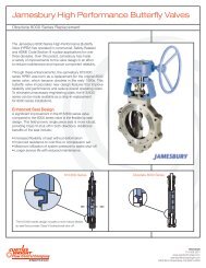
P R O C E S S V A L V E SWKM POW-R-SEAL API 6D THROUGH-CONDUIT GATE VALVESAPPLICATIONSWKM Model D High Temperature<strong>Pow</strong>-R-<strong>Seal</strong> Gate Valves in aSynthetic Natural Gas PlantWKM Model D <strong>Pow</strong>-R-<strong>Seal</strong> Gate Valveacting as a block valve in apipeline expansionTechnician demonstratingbonnet removaland in-line repair ofWKM Model EWKM Model E <strong>Pow</strong>-R-<strong>Seal</strong> Gate Valveson a gas storage manifoldWKM Model G Series <strong>Pow</strong>-R-<strong>Seal</strong>Gate Valve with a gas motor operator®22 WKMCT-WKM-POWRSEAL/GATE11/08 ION-3M
P R O C E S S V A L V E SWKM POW-R-SEAL API 6D THROUGH-CONDUIT GATE VALVESAPPLICATIONSWKM Model E <strong>Pow</strong>-R-<strong>Seal</strong> Gate Valves on the inlet to agas sweetening plantWKM Model E1 <strong>Pow</strong>-R-<strong>Seal</strong> Gate Valve used forisolation of a control valve in a liquids pipeline18 inch (450 mm) 600WKM Model E<strong>Pow</strong>-R-<strong>Seal</strong> Gate Valvein a block valveapplicationWKM Model G Series <strong>Pow</strong>-R-<strong>Seal</strong> Gate Valve in a block valveapplication on a pipeline loop - possibly a pigging loop.Note smaller WKM Model D <strong>Pow</strong>-R-<strong>Seal</strong>s possibly used as“kicker valves”WKM Model E <strong>Pow</strong>-R-<strong>Seal</strong> Gate Valve used for switching gasoline and otherrefined products on a tank farm manifoldWKM Model E <strong>Pow</strong>-R-<strong>Seal</strong> Gate Valveson an LPG storage wellhead®WKMCT-WKM-POWRSEAL/GATE11/08 ION-3M23
P R O C E S S V A L V E STRADEMARK INFORMATION®WKM is a registered trademark which is owned by Cameron.This document contains references to registered trademarks or product designations,which are not owned by Cameron.TrademarkInconelMonelStelliteTeflonVitonOwnerINCO Nickel Sales, Inc.INCO Alloys International, Inc.Stoody Deloro Stellite, Inc.E.I. DuPont De Nemours & CompanyE.I. DuPont De Nemours & Company24®WKM CT-WKM-POWRSEAL/GATE11/08 ION-3M
P R O C E S S V A L V E SVALVES & MEASUREMENT3250 Briarpark Drive, Suite 300Houston, Texas 77042USA Toll Free 800 323 9160For the most current contact and location information go to: www.c-a-m.com/valvesandmeasurementPrinted in Canada 11/08-ION-3M CT-WKM-POWRSEAL/GATERev. 11/08