Lossless DCâDC Boost Converter With High Voltage Gain For PV ...
Lossless DCâDC Boost Converter With High Voltage Gain For PV ...
Lossless DCâDC Boost Converter With High Voltage Gain For PV ...

Create successful ePaper yourself
Turn your PDF publications into a flip-book with our unique Google optimized e-Paper software.
Asian Transactions on Engineering (ATE ISSN: 2221 - 4267) Volume 02 Issue 04<br />
<strong>Lossless</strong> DC–DC <strong>Boost</strong> <strong>Converter</strong> <strong>With</strong> <strong>High</strong><br />
<strong>Voltage</strong> <strong>Gain</strong> <strong>For</strong> <strong>PV</strong> Technology<br />
Falah Al Hassan*, Vladimir L. Lanin<br />
*Electrical and Electronics Engineering Department, Eastern Mediterranean University, Famagusta,<br />
Cyprus, Email: falahalzobe@yahoo.com<br />
Electronic Technique and Technology Department, Belarus State University of Informatics and Radio<br />
electronics, Minsk, Belarus, Email:vlanin@bsuir.by<br />
<br />
Abstract— The demands of <strong>PV</strong> technology with high performance<br />
is very interesting alternative on supplement the electric system<br />
generation, due to the persistent cost reduction of the overall<br />
system a lot of works have been done during the design and<br />
implementation of high efficiency DC-DC converters applicable<br />
in <strong>PV</strong> . This paper proposes for improving the power-conversion<br />
efficiency and to obtain high voltage gain by reducing voltage<br />
stresses at a switch node of boost converter by using snubber cell<br />
which consists of inductors, capacitor, as well as diodes. In the<br />
proposed converter, two inductors with same level of inductance<br />
are charged in parallel during the switch –on period and are<br />
discharged in series during the switch-off period. Moreover the<br />
paper discusses the theoretical analyses in detail and present<br />
experimental result. Finally The improved boost converter<br />
topology was built in the laboratory to verify the performance<br />
with input voltage 15V to out 130 V and the typical operation<br />
frequency 30KHZ to get hold of efficiency between (90-94)%.<br />
Semiconductor power devices need snubber circuits<br />
because they have a limited safe operating area at turn-on and<br />
turn-off. The objective of a snubber circuit is to help the<br />
device during the switching transitions to survive the voltage<br />
and the current stresses. These stresses are due to the<br />
interruption of the current at turn-off and to the collapse of the<br />
voltage at turn-on. Numerous topologies of snubber circuits<br />
are available in the literature [4]-[6].<br />
keywords— <strong>PV</strong>,DC-DC boost converter, high voltage gain<br />
snubber circuit, high efficiency.<br />
P<br />
I. INTRODUCTION<br />
hotovoltaic <strong>PV</strong> power systems are one of today’s fastest<br />
growing renewable energy technologies. Solar cells, which<br />
are the foundation of <strong>PV</strong> systems, convert the energy in<br />
sunlight directly into electricity. A number of solar cells<br />
electrically connected to each other and mounted in a support<br />
structure or frame is called a photovoltaic module. Modules<br />
are designed to supply electricity at a certain voltage. Multiple<br />
modules can be wired together to form an array [1]-[3].<br />
In distributed generation (DG) systems, interfacing<br />
photovoltaic (<strong>PV</strong>) energy based sources to the grid poses a<br />
number of problems. Nowadays, transformerless converters<br />
are preferred for higher efficiency, low size low device<br />
stresses, and low current ripple. The output voltage of <strong>PV</strong><br />
arrays is relatively low, requiring a high step-up converter to<br />
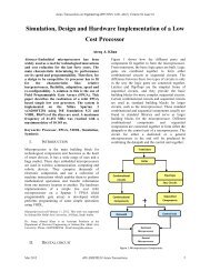
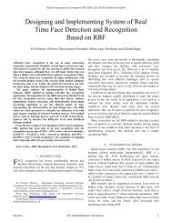
obtain the DC voltage input of the inverter. The <strong>PV</strong> power<br />
generation block diagram is composed of <strong>PV</strong>, <strong>Boost</strong> DC-DC<br />
<strong>Converter</strong>, energy storage element, and bidirectional DC-DC<br />
converter, as depicted in Fig. 1<br />
Fig.1. <strong>PV</strong> power generation block diagram.<br />
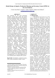
Many step-up switch structures have been presented to<br />
provide a high efficiency without extremely high duty ratio<br />
and for reducing the output current ripple [8]-[10].the basic<br />
step-up inductors block is given in fig.2. Accordingly, for this<br />
block during the switch –on period and are charged in<br />
parallel as shown in fig.2a and during off period and are<br />
charged in series as shown in fig.2a.<br />
September 2012 ATE-10216041©Asian-Transactions 24
Asian Transactions on Engineering (ATE ISSN: 2221 - 4267) Volume 02 Issue 04<br />
( ) [ ( )][ ] ( ) (2)<br />
( ) [ ( ) ]<br />
(3)<br />
Where :<br />
Fig.2. Inductors block.( a) inductors block when switch turn –on (b) inductors<br />
block when switch turn –off<br />
√<br />
II. OPERATIONAL ANALYSIS OF PROPOSED BOOST CONVERTER<br />
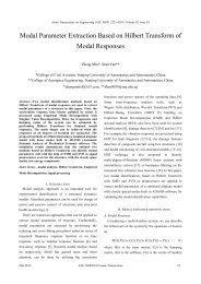
The configuration topology of the proposed converter with<br />
soft switching scheme is shown in Fig.3, the switch , , ,<br />
, , , and are the main boost converter<br />
components, while R represents the resistive load on the<br />
converter. Inductor , , , and form the auxiliary<br />
circuit for accomplishing the soft switching of . Inductors<br />
and are much smaller than , and is much smaller<br />
than .<br />
When<br />
stops conducting and this stage comes to an end.<br />
2) Stage 2: The initial conditions on , and are,<br />
( ) , ( ) respectively, attained at the<br />
end of. Stage 1.The expressions are Eq. 4-6:<br />
( ) ( )[ ]<br />
( )<br />
( ) (4)<br />
( )<br />
( )<br />
[ ]<br />
( ) (5)<br />
( )<br />
( )<br />
[ ]<br />
( ) (6)<br />
Where:<br />
Fig.3. The proposed high voltage gain dc-dc boost converter<br />
√( )<br />
The operating stages of the proposed topology can be divided<br />
into seven stages:<br />
1) Stage 1: This stage begins with the turn on of , at zero<br />
current at .The expressions are Eq. 1-3:<br />
( )<br />
Where and with the same level of inductance are charged<br />
parallel.<br />
This stage comes to an end when reaches zero at .<br />
( ) (1)<br />
September 2012 ATE-10216041©Asian-Transactions 25
Asian Transactions on Engineering (ATE ISSN: 2221 - 4267) Volume 02 Issue 04<br />
3) Stage 3: The initial conditions on , and for<br />
this stage. ( ), ( )are zero. The expression for<br />
( ) is:<br />
7) Stage 7: In this stage , are zero. This stage comes to<br />
an end at when is turned on at zero current. This is the<br />
normal stage of the boost converter. The expressions are:<br />
( ) [ ] (15)<br />
( )<br />
( )<br />
( ) (7)<br />
This stage comes to an end at when reaches zero at .<br />
4) Stage 4: In this stage current buildup in and and ( )<br />
are governed by the Eq. as follows.<br />
( )<br />
( )<br />
(8)<br />
( )<br />
( ) ( )<br />
[( )<br />
( ) ] ( )<br />
Where :<br />
( )<br />
( )<br />
(9)<br />
√<br />
( )<br />
Where:<br />
( ) ( ) ( )<br />
Where is the equivalent inductance for parallel equivalent<br />
inductors and .<br />
This stage comes to an end when is turned off at zero<br />
voltage at .<br />
5) Stage 5: This stage begins with the turn off of at zero<br />
voltage at .The expressions are:<br />
( )<br />
( ) ( ) (10)<br />
[ ( )] (11)<br />
( )<br />
[ ( )] (12)<br />
( )<br />
6) Stage 6:In this stage reduces to zero. This stage<br />
comes to an end at when becomes<br />
zero. The expression for and for these stage is.<br />
( )<br />
( ) (13)<br />
Where is the equivalent inductance for equal series<br />
inductors and .<br />
III. EXPERIMENTAL RESULTS<br />
Prototype circuit is built in the laboratory To verify the<br />
theoretical analyses of proposed converter for use in <strong>PV</strong><br />
application, the circuit specifications and components Are<br />
selected as =15V, = 70 to 130V, = 330ρF and<br />
=100µF. = =130µH, =5.4ρH, =3.3pH.Moreove<br />
r, IGBT HGTG20N60B is selected for switch s1and ultra fast<br />
diode 60EPU04P is used for , , and .Moreover, two<br />
diodes 6A05 selected for and .<br />
Under the condition =15V and the switch frequency<br />
=30KHZ, some experimental results at duty cycle 80%are<br />
shown in Fig.4. and it shows that the mean power input is<br />
approximately equal 35W moreover the output voltage is<br />
equal 130V .<br />
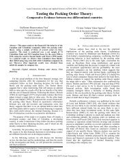
Fig.5. shows the experimental efficiency of the proposed<br />
converter according the output voltage range. The proposed<br />
converter can achieve high step-up voltage gain as shown in<br />
Fig. 6.<br />
( ) [ ( ) ][ ](<br />
( )<br />
) (14)<br />
September 2012 ATE-10216041©Asian-Transactions 26
Asian Transactions on Engineering (ATE ISSN: 2221 - 4267) Volume 02 Issue 04<br />
IV. CONCLUSION<br />
This paper has presented a lossless dc-dc boost converter<br />
with high step-up voltage gain for the low output photovoltaic<br />
voltage. The major advantages for this topology are high<br />
boosting ratio with low voltage stress on the switch, low size<br />
and cost .The parallel/series inductors cell with snubber cell<br />
based on the active switch of proposed topology investigated<br />
and a circuit prototype with an output of 130V with efficiency<br />
(90-94)% is designed .The experimental results have proven<br />
good performances and verify the feasibility of the proposed<br />
circuit, and the voltage gain can be achieved for low output<br />
photovoltaic problem . More future work will highlight to<br />
decrease the voltage stress on the drive switch with a<br />
promising cost, size, and efficiency optimization.<br />
Fig.4. Experimental result for proposed topology<br />
ACKNOWLEDGMENT<br />
I would like to express my sincere gratitude to Mr. Said<br />
Abdalla and Ms Sabriah Halhoul and Arca family for<br />
invaluable help and support all over this work.<br />
REFERENCES<br />
Fig.5. The experimental efficiency of the proposed converter<br />
according the output voltage range<br />
[1] W. Jianqiang, and L. Jingxin, “Design and experience of gridconnecting<br />
photovoltaic power system”, IEEE international conference on<br />
sustainable energy technologies ICSET 2008, Pp 607-610, Singapore,<br />
2008.<br />
[2] M. C. Cavalcanti, G. M. S. Azevedo, B. A. Amaral, K. C. de Oliveira, F.<br />
A. S. Neves, and Z. D. Lins, “Efficiency evaluation in grid connected<br />
Photovoltaic energy conversion systems”, IEEE 36th power electronics<br />
Specialist conference, Pp 269-275, Brazil, 2005.<br />
[3] S. Mekhilef, N. A. Rahim, and A. M. Omer, “A new solar energy<br />
conversion scheme implemented using grid-tied single phase inverter”,<br />
Proceedings of IEEE TENCON-2000, Kuala Lumpur, Malaysia, 2000.<br />
[4] F. Al Hassan. “Transformerless Battery Charger by Using Constant<br />
Current/Constant <strong>Voltage</strong> Controller”. Circuits and Systems. No.2, 2012.<br />
pp. 180–186<br />
[5] B.-T. Irving, and M.-M. Jovanovic, “Analysis, design, and performance<br />
Evaluation of flying-capacitor passive lossless snubber applied to PFC<br />
boost converter,” Applied Power Electronics Conference and<br />
Exposition, Vol. 1, 2002, pp. 503-508.<br />
[6] J.-H. Kim, Y.-C. Jung, S.-W. Lee, T.-W. Lee, and C.-Y. Won, “Power loss<br />
Analysis of interleaved soft switching boost converter for single-phase<br />
pv-pcs,” Journal of Power Electronics, Vol. 10, No. 4, pp. 335-341, Aug.<br />
2010.<br />
[7] B. Axelrod, Y. Berkovich, and A. Ioinovici, “Switched capacitor /switched<br />
inductor structures for getting transformerless hybrid dc–dc pwm<br />
converters,” IEEE Transactions On Circuits And Systems-I: Regular<br />
Papers, Vol. 55, No. 2, March 2008..<br />
[8] L. S. Yang, T. J. Liang, and J. F. Chen,―Transformerless DC-DC<br />
converters with high step-up voltage gain”, IEEE Trans. Ind. Electron.,<br />
vol. 56,no. 8, pp. 3144-3152, Aug. 2009.<br />
[9] J. K. Park, w. Y. Choi, and B. H. Kwon, “Step-up DC–DC converter<br />
with a resonant voltage doubler”, IEEE transactions on industrial<br />
Electronics, Vol.54, Issue-6, Pp 3267-3275, 2007.<br />
[10] Yungtaek Jan, and Milan M. Jovanovic. “A New Two-Inductor <strong>Boost</strong><br />
<strong>Converter</strong> with Auxiliary Transformer”, in IEEE Transactions on<br />
Power Electronics, Vol. 19, No1, January 2004, pp. 169-175.<br />
Fig.6. The proposed converter voltage gain verses duty cycle<br />
September 2012 ATE-10216041©Asian-Transactions 27
Asian Transactions on Engineering (ATE ISSN: 2221 - 4267) Volume 02 Issue 04<br />
Falah AL Hassan was born in Jordan in 1978.He<br />
received the B.S of Science in the section of Electric<br />
Engineering from Princess Sumaya University for<br />
Technology / Royal Scientific Association in Jordan<br />
in 2001. And high honor M.S. degrees of Science in<br />
Electrical and Electronic Engineering from Eastern<br />
Mediterranean University in Cyprus in 2010. He is<br />
currently working toward the Ph.D. degree. He is a<br />
member of Jordan and Cyprus Section IEEE and<br />
Member of Jordanian Engineers Syndicate.<br />
He has 9years experience works: Electric<br />
Engineering Officer at the Jordanian Armed <strong>For</strong>ces / Royal Maintenance<br />
Armament, Jordan Telecommunications Company (JTC), Jordan Ministry of<br />
Energy, power system lab in Electrical and Electronic EMU. he is author of<br />
five international papers His main research interests include dc-dc converter<br />
ac-dc converter ,power maintenance ,design high efficiency converters for <strong>PV</strong><br />
system, and Ultrasonic Technology.<br />
Vladimir Lanin received the PhD in Electronic<br />
Engineering at Sanct Petersburg Technical Institute,<br />
Russia in 1982. He is Dr. Sci. Tech., professor at the<br />
Electronic Engineering and Technology Department<br />
of the State University of Informatics and<br />
Radioelectronics, Minsk, Belarus.<br />
He is a member of Belarus Section IEEE. He has<br />
more than 25 years of experience in Ultrasonic<br />
Technology and Technology of Electronics<br />
Production. Basic research area: technology of<br />
electronic devices. He is the author of books:<br />
“Ultrasonic Soldering in Radio and Device Production” 1985, “Ultrasonic<br />
Processes in Electronics Production” in 2 volume 2002, and 2003, “<br />
<strong>For</strong>mation of Сurrent–carring Contact Connections in Electronics Devises”<br />
2007, publishing in Belarus.<br />
September 2012 ATE-10216041©Asian-Transactions 28