Drillfloor equipment - Aker Solutions
Drillfloor equipment - Aker Solutions
Drillfloor equipment - Aker Solutions

You also want an ePaper? Increase the reach of your titles
YUMPU automatically turns print PDFs into web optimized ePapers that Google loves.
<strong>Aker</strong> 21 <strong>Solutions</strong><br />
Drilling Technologies<br />
<strong>Aker</strong> <strong>Solutions</strong> 21<br />
Drilling Technologies<br />
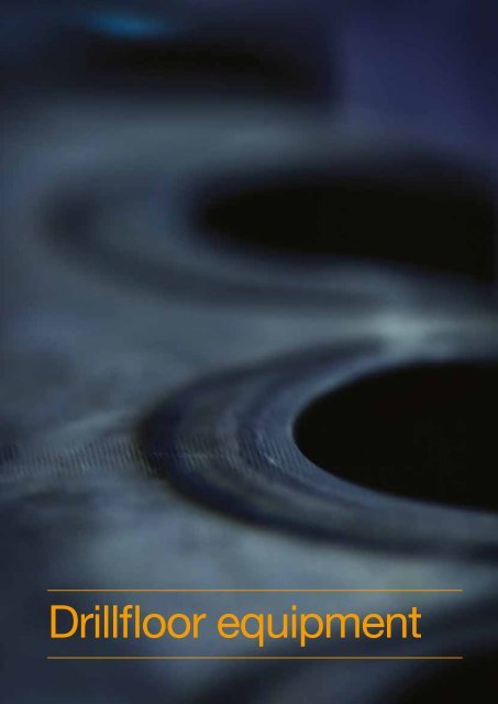
<strong>Drillfloor</strong> <strong>equipment</strong>
22 <strong>Aker</strong> <strong>Solutions</strong><br />
Drilling Technologies<br />
<strong>Drillfloor</strong> <strong>equipment</strong><br />
MH hydraulic roughneck<br />
The mainstream hydraulic roughneck portfolio<br />
contains three models<br />
• Model 1898 - manually operated<br />
• Model 1899 - automatically operated<br />
• Model 4160 - lightweight version of model 1898<br />
Key features<br />
• Designed for optimum performance, quality and<br />
reliability<br />
• Designed to spin in/make up and break<br />
out/spin out drill pipe and drill - in a pre-defined<br />
sequence if equipped with automatic controls<br />
• Make up / break out stabilisers, crossover subs<br />
and other bottom hole assemblies<br />
• Performs mousehole connections<br />
• Minimise the possibility of personnel injuries,<br />
<strong>equipment</strong> damage and interruption of<br />
operations<br />
• Possibility to run all functions from the driller’s<br />
controls room or from radio remote panel<br />
Handling capabilities<br />
• Diameter range: 2 7/8” - 9 3/4”<br />
• Vertical and inclined tubulars (inclined as in tilted<br />
mouseholes)<br />
• Various tools: BHA/drill bit, stabilizers, strainers<br />
and subs.<br />
We can adapt the machine to various rail systems<br />
(e.g. skiddable, hinged, bolted). Models 1898 and<br />
1899 are also available on extension arm.<br />
Optional features<br />
• Revolving pipe spinner assembly (improves<br />
utilisation range and service access)<br />
• Automatic lubrication system<br />
• Inverted main frame<br />
• Various rail systems (e.g. skiddable, hinged, bolted)<br />
• Remote operated box end washer and doping unit<br />
• Break out torque record gauge<br />
• Stabbing guide arm<br />
• Special jaws for odd tooljoint size/shape/material<br />
• Control panel on machine<br />
• Wireless remote control (radio)<br />
• High friction spinner rollers available upon request<br />
Technical data<br />
Models 1898 and 1899 Standard Optional Unit<br />
TW min. make-up torque 11500 [8500] 5425 [4,000] Nm [lbf ft]<br />
TW max. make-up torque 135000 [100000] Nm [lbf ft]<br />
TW max. break-out torque 169000 [125000] Nm [lbf ft]<br />
TW min. stick-up height 700 [27.5] mm [inch]<br />
TW max. stick-up height 1500 [59] 2200 [86] mm [inch]<br />
SP max. speed (w/5 ½” D.P) 0-160 0-80 rpm<br />
SP max. torque (w/5 ½” D.P) 2750 [2 028] 5500 [4,050] Nm [lbf ft]<br />
SP travel height 500 [19.7] 900 [35.4] mm [inch<br />
Mousehole tilt 0-5°bwd 0-15° bwd / 0-8°fwd Degr<br />
Rail span (outside/outside) 1850 [72.8] 1120-2614 [44.1-102.9] mm [inch]<br />
Weight will vary from 5900 (13,000 lb) kg to 6300 kg (13,900 lb) depending on configuration and options.<br />
Technical data<br />
Model 4160 light weight Data Unit<br />
TW min. make-up torque 5 300 [3 900] Nm [lbf ft]<br />
TW max. make-up torque 84000 [62000] Nm [lbf ft]<br />
TW max. break-out torque 105000 [77500] Nm [lbf ft]<br />
TW min. stick-up height 700 [27.5] mm [inch]<br />
TW max. stick-up height 1500 [59] mm [inch]<br />
SP max. speed (w/5 ½” D.P) 0-160 rpm<br />
SP max. torque (w/5 ½” D.P) 2750 [2 028] Nm [lbf ft]<br />
SP travel height 500 [19.7] mm [inch<br />
Mousehole tilt 0-5°bwd Degr<br />
Rail span (inside/inside) 1200 [47.2] mm [inch]
<strong>Aker</strong> <strong>Solutions</strong><br />
Drilling Technologies<br />
<strong>Drillfloor</strong> <strong>equipment</strong><br />
23<br />
MH hydraulic roughneck<br />
with three grip torque wrench<br />
The recently developed three grip torque wrench<br />
is now available with the 1898/1899 roughneck<br />
system. The new design incorporates the<br />
efficiency and handling capabilities of the<br />
original MH torque wrench, into a new higher<br />
performance tong. Designed for making up<br />
and breaking out the most resilient drill pipe<br />
and collar connections, the new three grip tong<br />
features up to 150.000 ft-lbs torque capacity<br />
and 60° rotation.<br />
Three grip torque capacity<br />
Three grip configuration secures 50% higher<br />
torque capacity compared to a two-grip<br />
tong with equivalent clamp force. The clamp<br />
force can accordingly be reduced by 33% for<br />
corresponding torque setting. Reduced clamp<br />
force means less wear on tool joint and reduced<br />
risk of radial deformation of box end. Rotational<br />
force is applied through chains, securing an<br />
optimal radial bearing around the rotating tong’s<br />
circumference.<br />
Upgrade<br />
The HRN with three grip torque wrench is suitable<br />
for any new build or upgrade project. The new<br />
tong utilises the same framework and rails as<br />
the MH 1898/1899 machines, and is therefore<br />
suitable for installation on rigs where a MH<br />
roughneck is currently installed. As there not<br />
have been incorporated any new instruments,<br />
a new machine can be installed in existing MH<br />
roughneck interface.<br />
Improved safety<br />
The tong also incorporates a new jaw design for<br />
improved safety and efficiency. Worn-out dies<br />
are easily removed by disengaging a socket<br />
cap bolt, no need for hammer and chisel. Less<br />
time required to change dies, means less time<br />
spent in the “red zone” on rig floor.<br />
Technical data<br />
Standard Optional Unit<br />
TW rotation 60 degrees<br />
TW range 2 3/8” – 10” inch<br />
TW min. make-up torque 7 400 [5 450] Nm [ft. lbs]<br />
TW max. make-up torque 185 000 [136 000] Nm [ft. lbs]<br />
TW max. break-out torque 185 000 [136 000] Nm [ft. lbs]<br />
TW max. bit-break/back-up torque 75 000 [55 000] Nm [ft. lbs]<br />
TW min. stick-up height 700 [2.33] mm [ft]<br />
TW max. stick-up height 1500 [59] 2 100 [7.25] mm [ft]<br />
SP max. torque (w/5 ½” D.P) 2750 [2028] 4 475 [3 300] Nm [lbf. ft]<br />
SP max. speed (w/5 ½” D.P) 0-136 0 – 80 rpm<br />
SP travel height 500 [19,7] 900 [35,4] mm [inch]<br />
Rail span (outside/outside) 1850 [72,8] 1480-2650<br />
[58,3-104,3]<br />
mm [inch]
24 <strong>Aker</strong> <strong>Solutions</strong><br />
Drilling Technologies<br />
<strong>Drillfloor</strong> <strong>equipment</strong><br />
MH DRN 200<br />
The MH DRN 200 is a patented machine made for<br />
making up and breaking out drill pipe, drill collars and<br />
casing. The clamping range is from 2 3/8” to 20” with<br />
a torque capacity of 203 000 Nm (150 000 ft-lbs). It<br />
is based on two tongs that can be separated and is<br />
thereby also capable of handling stabilizers and bits.<br />
In addition, the MH DRN 200 has a make up and<br />
break out torque capacity of 68 000 Nm (50 000 ft-lbs)<br />
between its main tong and drill floor and between<br />
the top drive and its backup tong, giving a unique<br />
operational freedom.<br />
Integrated into the design is also a spinner, casing<br />
guide, thread washing and lubrication system. The<br />
MH DRN 200 travels on rails welded or bolted to the<br />
drill floor, thus reaching the centre of rotary table. The<br />
wheels are hydraulically driven giving positive drive for<br />
the travel by means of constant mesh sprocket to rail.<br />
The design criteria were set to improve HSE for drill<br />
floor activities, save cost and to improve efficiency.<br />
Improved HSE<br />
• The spinner stabbing feature and casing stabbing<br />
guide ensures hands-free operation of drill pipe and<br />
casing.<br />
• The upper and lower tongs can be elevated<br />
separately, allowing the machine to act as rig tongs,<br />
and to make up and break out odd pieces such as<br />
stabilizers and bits.<br />
• Integrated washing and pipe doping (on box<br />
end) makes this a hands free operation as well, and<br />
removes people from the most dangerous area.<br />
• Since the casing tongs are integrated into the<br />
machine, the need for rigging up and down heavy<br />
casing tongs are eliminated, which in turn removes<br />
the risk for incidents related to drill floor handling.<br />
• Reduced number of machines on drill floor<br />
necessary for drilling operations<br />
Saved cost<br />
• No need for hiring casing tongs. The cost of hiring<br />
or purchasing casing tongs is removed.<br />
• Ordinary drilling crew can operate the casing tong.<br />
The acceptance or rejecting of pipe connections<br />
can be done onshore, as the control system is<br />
prepared for remote transfer of data. Reduced cost<br />
for casing crew and supervisor.<br />
• No need for separate drill pipe doping devices<br />
• Enabling more compact drill floor installations<br />
Design data<br />
Society of classification<br />
Equipment classification<br />
Design temperature<br />
Acc. to DnV (Det norske Veritas)<br />
II<br />
-20 / +45 °C (-4 / +113°F)<br />
Technical data<br />
Max. makeup torque 203 000 Nm (150 000 ft.lbs.)<br />
Max. breakout torque 203 000 Nm (150 000 ft.lbs.)<br />
Max. MU/BO torque between MT/DF & TD/BUT 68 000 Nm (50 000 ft.lbs.)<br />
Bit brake plate - Lower locator square 345 mm 13 9/16”<br />
Spinning range 60-245 mm (2 3/8” – 9 5/8”)<br />
Guiding range 60-508 mm (2 3/8” – 20”)<br />
Max. spinning torque (5” DP) 2300 Nm (1700 ft.lbs.)<br />
Max. spinner rpm (5” DP)<br />
0-100 rpm<br />
Vertical independent spinner travel 600 mm (23 ½”)<br />
Min. distance center MT- center roller 1150 mm (45”)<br />
Max. tong rpm<br />
15 rpm<br />
Max. travel speed 500 mm/s (20 in/s)<br />
Max. vertical travel (tong/spinner) 1500 mm (59”)<br />
Handling range (pipe/casing) * 60-508 mm 2 3/8” – 20”<br />
Min. MU/BO stick up 540 mm (21 ½”)<br />
Max. MU/BO stick up 1900 mm (75”)
<strong>Aker</strong> <strong>Solutions</strong><br />
Drilling Technologies<br />
<strong>Drillfloor</strong> <strong>equipment</strong><br />
25<br />
Improved efficiency<br />
• Time required for handling of casing tongs, which<br />
is directly at the sacrifice of operational time, is<br />
saved.<br />
• No time lost due to module replacement on the<br />
MH DRN 200 - the tongs take all dimensions<br />
with a minimum of preparation.<br />
• Logistics of spare parts is reduced, as well as the<br />
casing tongs themselves.<br />
• Due to the continuous rotation of the main tongs,<br />
wedge thread (WT) and other difficult thread types<br />
can be made up with less cycle time compared to<br />
a traditional iron roughneck.<br />
• Torque-turn monitoring not only available when<br />
running casing, but also for drill pipe operations.<br />
This enables even more sophisticated thread<br />
connections with increased performance.<br />
The control system and the computerized make<br />
up system (CMU) provide the following network<br />
interfaces:<br />
• Ethernet to the MH DrillView<br />
• Ethernet or field bus to smart zone management<br />
system (SZMS)<br />
• SZMS and other control system nodes<br />
• Open field bus to remote I/O and operator panels<br />
The MH DRN 200 control system provides an OLE for<br />
process control (OPC) server and client interface for<br />
data exchange with MH DrillView and other control<br />
systems.<br />
The control system provides an interface for remote<br />
diagnostics using web or telephone services.<br />
Control system<br />
The control system cabinet is placed in the local<br />
instrument room. The field instruments are terminated<br />
locally on remote I/O modules accessible on field<br />
bus. All input and output devices meet the NORSOK<br />
standard for offshore installation.<br />
CPU and software<br />
The MH DRN 200 control system utilises a centralised<br />
computer located in the LIR. The soft programmable<br />
logic controller (PLC) provides closed loop control of<br />
multiple axes. The computerized make-up system is<br />
implemented on the same PC as the soft PLC using<br />
standard PC tools for recording of data interface.
26 <strong>Aker</strong> <strong>Solutions</strong><br />
Drilling Technologies<br />
<strong>Drillfloor</strong> <strong>equipment</strong><br />
MH drillfloor manipulator arm<br />
The MH drillfloor manipulator arm (DFMA) is designed<br />
to guide tubulars on drillfloor level. The DFMA is<br />
used for guiding drill pipes, collars and risers from<br />
chute to well-center, or to setback area. The control<br />
of the DFMA is accomplished from a remote control<br />
panel on drill floor. The operator has full control of all<br />
functions.<br />
Key features<br />
• Designed to guide tubulars on drill floor level. It is<br />
used for guiding and tailing in drill pipes, collars<br />
and risers<br />
• The DFMA is either mounted on drill floor by<br />
a sub frame that is welded to drill floor, or it<br />
is mounted in an inverted position, normally<br />
suspended from underneath the support structure<br />
for the drilling machine guide rails<br />
• A lifting lug can optionally be installed underneath<br />
the racker head in order to use the DFMA for lifting<br />
of different objects on the drill floor<br />
If a control system is included in the delivery, this<br />
system allows<br />
• Control from operators chair in drillers cabin<br />
• An optional radio panel allowing full control of all<br />
functions of the manipulator arm<br />
• Possibility to integrate with rig’s anti-collision<br />
system<br />
> MH drillfloor<br />
manipulator arm
<strong>Aker</strong> <strong>Solutions</strong><br />
Drilling Technologies<br />
<strong>Drillfloor</strong> <strong>equipment</strong><br />
27<br />
MH multi manipulator arm<br />
The MH multi manipulator arm (MMA) is designed<br />
to guide tubulars on drillfloor level. The MMA can be<br />
delivered in three different designs;<br />
MMA variant 1 and 2 are specifically designed to lift<br />
subs, bottom hole assemblies and other special items<br />
on drillfloor level. They are also suitable for guiding<br />
tubulars between the V-door and the well center/<br />
setback area.<br />
MMA variant 3 is designed to guide risers, collars and<br />
other tubulars on drillfloor level.<br />
Key features<br />
• The MMA is a compact, pedestal mounted guide<br />
arm designed for minimum operating/guiding<br />
radius<br />
• A lifting lug can optionally be installed underneath<br />
the racker head in order to use the MMA for lifting<br />
of different objects on the drill floor<br />
If a control system is included in the delivery, this<br />
system allows<br />
• Control from operators chair in drillers cabin<br />
• An optional radio panel allowing full control of all<br />
functions of the manipulator arm<br />
• Possibility to integrate with rig’s anti-collision<br />
system<br />
> MH drillfloor<br />
manipulator arm
28 <strong>Aker</strong> <strong>Solutions</strong><br />
Drilling Technologies<br />
<strong>Drillfloor</strong> <strong>equipment</strong><br />
MH mud bucket<br />
> MH mud bucket<br />
retracted<br />
The MH mud bucket is designed for safe and smooth<br />
leading of drilling mud to tank whilst;<br />
- increasing safety<br />
- improving working environment<br />
- saving natural environment<br />
- reducing mud costs<br />
The MH mud bucket is suspended to the foundation<br />
via the extension arm. The foundation comprises a<br />
pedestal suspension with guiding column, bolted<br />
to a foundation plate welded to the drill floor. The<br />
extension arm enables extension and retraction of the<br />
bucket between parked position and the well centre<br />
by means of a hydraulic cylinder with stainless steel<br />
rod, piping and bearings.<br />
The bucket latches on to the drill string by means<br />
of three hydraulic cylinders with stainless steel rod,<br />
piping and bearings. It then leads the mud through the<br />
drain hose terminating in the exit interface, located on<br />
drill floor and connected to the mud tank. When the<br />
mud has been drained from the bucket, the bucket<br />
clamps off and the extension arm retracts the bucket<br />
to parked position.<br />
Technical data<br />
Max. travel length 2 800 [9.2] mm [Feet] Retraction length (guide<br />
column c/c - bucket c/c)<br />
1 700 [5.6] mm [Feet]<br />
Extension length (guide column c/c<br />
- bucket c/c)<br />
4 300 [14.1] mm [Feet] Slewing sector<br />
(manual for parking pos.)<br />
± 133 Degr<br />
Range, pipe seals<br />
2 7/8”-3½”-4”-5”-5½”-5<br />
7/8”-6 5/8”<br />
Inch<br />
Time cycle (bucket open<br />
– close)<br />
Time cycle (extension arm – retract) 8-10 Sec. Time cycle (extension arm<br />
– extend)<br />
2-3 Sec.<br />
8-10 Sec.<br />
Drain hose size 6” Inch Drain hose length 6 000 [19.7] mm [Feet]
<strong>Aker</strong> <strong>Solutions</strong><br />
Drilling Technologies<br />
<strong>Drillfloor</strong> <strong>equipment</strong><br />
29<br />
MH winches<br />
> MH utility winch<br />
The portfolio covers complete stand-alone and<br />
package integrated winch units/systems designed<br />
with special emphasis on safe, efficient and reliable<br />
operations:<br />
• MH utility winch<br />
• MH manriding winch<br />
• MH guideline winch<br />
• MH podline winch<br />
Description<br />
The winches are delivered as complete units, fully<br />
tested and ready for horizontal mounting by means of<br />
bolting to substructure and connection to hydraulic<br />
ringline systems.<br />
Typically comprise<br />
• Gearbox<br />
• Drum<br />
• Failsafe brake system<br />
• Hydraulic motor<br />
• Counter balance valve<br />
• Local control panel<br />
> MH manrider winch<br />
> MH podline winch<br />
Short-time installation is achieved as no special tools<br />
are required for this operation. All winches are fitted<br />
with lifting lugs for safe and easy handling. Safe,<br />
smooth and user friendly operation and control are<br />
performed from the local control panel. Due to high<br />
reliability, maintenance is briefly limited to periodic<br />
lubrication and filter replacements.<br />
Optional features<br />
• Hydraulic remote control panel (portable or fixed)<br />
• Portable wireless control panel<br />
• Hydraulic power unit<br />
• Wire spooling system<br />
• Snatch block<br />
An extensive range of alternatives and options<br />
completes our portfolio with the intention to suit any<br />
specific or special requirement.<br />
Technical data<br />
SWL Rope dia. x length Weight (incl. rope)<br />
MH UW - 5mT 5mT (11020 lbf) 19 mm (0.74”) 150 m (492´) 1500 kg (3300 lb)<br />
MH UW - 10mT 10mT (22050 lbf) 26 mm (1.02”) 150 m (492´) 2300 kg (5070 lb)<br />
MH MW - 150 kg 0.15mT (330 lbf) 10 mm (0.39”) 140 m (460´ 1050 kg (2300 lb)<br />
MH GLW - 10mT 10mT (22050 lbf) 26 mm (1.02”) 1200 m (3940´) 9600 kg (21150 lb<br />
MH GLWS-7.5mT 7.5mT (22050 lbf) 19 mm (0.74”) 1500 m (4925’) 9600 kg (21150 lb
30 <strong>Aker</strong> <strong>Solutions</strong><br />
Drilling Technologies<br />
<strong>Drillfloor</strong> <strong>equipment</strong><br />
MH hydraulic cathead<br />
The MH hydraulic cathead is a hydraulic tool for<br />
making up and breaking out drill pipe and drill collar. It<br />
is normally used together with a wire and a rig tong.<br />
Key features<br />
• Designed for optimum performance, quality and<br />
reliability<br />
• Equipped with integrated tong post and back-up<br />
post<br />
• Can be either electrically or pneumatically<br />
controlled<br />
• Can be equipped with an optional low torque<br />
functionality enabling making up and breaking<br />
out delicate tubulars.<br />
Technical description<br />
• The cathead is a hydraulic tool for making up<br />
and breaking out drill collar and drill pipe. It is<br />
a floor mounted self-contained unit, bolted to the<br />
drillfloor with 6 bolts.<br />
• The cathead unit consists of a base, cylinder,<br />
sheaves, and wire.<br />
• A combined tong post and back up post bracket<br />
is mounted on the cathead.<br />
• The electrically controlled cathead comes with<br />
a control valve cabinet (CVC). The CVC can be<br />
electrically connected to an electrical control<br />
system. The CVC is designed to control one or<br />
two catheads, and is normally placed on drillfloor.<br />
• The pneumatically controlled cathead comes<br />
with a control valve unit (CVU) and a pneumatic<br />
operator panel. The operator panel is normally<br />
installed on drill floor. Each cathead requires a<br />
separate operator panel and control valve unit<br />
(CVU).<br />
Technical data<br />
Control Pull regulation Low torque pull regulation Catheads<br />
Pneumatic 12 - 140 kN (2.7 - 31.5 kip) 0.85 - 13.6 kN (0.2 - 3.1 kip) 1<br />
Electrical 12 - 140 kN (2.7 - 31.5 kip) 4.0 - 44.0 kN (0.9 - 10.0 kip) 1 or 2<br />
> MH hydraulic<br />
cathead in<br />
operation