WJ-9205 Control Moni.. - of Peter Gottlieb
WJ-9205 Control Moni.. - of Peter Gottlieb
WJ-9205 Control Moni.. - of Peter Gottlieb

Create successful ePaper yourself
Turn your PDF publications into a flip-book with our unique Google optimized e-Paper software.
+-+--l--+---+---+-~+---f--l--+--+---+---ir-+--+-+-+-+-+--+--II-+--+-+-+-+--+-~I-+-+-+--+-+--t--+--I--t--+-+-l-+--+--+--I-+-~ +-+--+-+ -+- +<br />
~;}---l--t-+--+--t---+-1-+-+--+-+-+-+-+--t----+-----+------+-+---+-+----+-t-+--+---+-+---t-+-+-t--+-+--+---+---+----+--t--It-+-+-+-+-+----+-+-+-i-t-t--t-t +<br />
- 1---+ 1-.- - f-<br />
- t-+-+--+-1-+--+-t--+-+-++-+---+<br />
1 '<br />
INSTRUCTION MANUAL<br />
FOR THE<br />
<strong>WJ</strong>-<strong>9205</strong> SIGNAL MONITOR<br />
-<br />
I<br />
r1ṯ -+--+-+-+-f-+-t--+-+-+-+-+--+-+-+-+-+--i--+-+-+-l-+-+--It-+--+-f-+--+-t-+-+-+-+-+-+-+-+-+-+-+-+-+-+-+-l---+--1-t-+--+-+-+-+<br />
I~<br />
-<br />
l;.i<br />
~ ';
INSTRUCTION MANUAL<br />
FOR THE<br />
<strong>WJ</strong>-<strong>9205</strong> SIGNAL MONITOR<br />
WATKINS-JOHNSON COMPANY<br />
700 QillNCE ORCHARD ROAD<br />
GAITHERSBURG, MARYLAND 20878<br />
October 1989
WARNING<br />
This equipment utilizes voltages which are<br />
potentially dangerous and may be fatal if contacted.<br />
Exercise extreme caution when working<br />
with the equipment with any protective cover<br />
removed.<br />
PROPRIETARY STATRMRNT<br />
This document and sUbject matter disclosed<br />
herein are proprietary items to which Watkins<br />
Johnson Company retains the exclusive right <strong>of</strong><br />
dissemination, reproduction, manufacture and<br />
sale.<br />
This document is provided to the individual or<br />
using organization for their use alone in the<br />
direct support <strong>of</strong> the associated equipment<br />
unless permission for further disclosure is<br />
expressly granted in writing.
<strong>WJ</strong>-<strong>9205</strong> INSTRUCTION MANUAL<br />
REVISION A CHANGE 1<br />
<strong>WJ</strong>-<strong>9205</strong> SIGNAL MONITOR<br />
REVISION A CHANGE 1<br />
TITLE:<br />
MANUAL DATE:<br />
CHANGE 1<br />
DATE:<br />
APPLICABILITY:<br />
CHANGES/ERRATA<br />
INFORMATION:<br />
CHANGE 1<br />
SUMMARY:<br />
INSTRUCTION MANUAL FOR THE <strong>WJ</strong>-<strong>9205</strong> SIGNAL MONITOR<br />
October 1989<br />
February 1990<br />
All units.<br />
Changes refer to updates <strong>of</strong> the manual to cover design modifications.<br />
Errata refer to corrections or clarifications <strong>of</strong> information<br />
in the manual.<br />
This change provides additional information for the Remote<br />
Mnemonics Table.<br />
ERRATA:<br />
page 2-15<br />
Add the following remote mnemonic after STS?<br />
ASCII HEX DEC Description<br />
STV(a) C5 197 Stores selected trace to<br />
memory<br />
A-C1-1
<strong>WJ</strong>-<strong>9205</strong> INSTRUCTION MANUAL REVISION A CHANGE 2<br />
<strong>WJ</strong>-<strong>9205</strong> SIGNAL MONITOR<br />
REVISION A CHANGE 2<br />
TITLE:<br />
INSTRUCTION MANUAL FOR THE <strong>WJ</strong>-<strong>9205</strong> SIGNAL MONITOR<br />
MANUAL DATE: October 1989<br />
CHANGE 1<br />
DATE: May 1990<br />
APPLICABILITY:<br />
All units.<br />
CHANGES/ERRATA<br />
INFORMATION: Changes refer to updates <strong>of</strong> the manual to cover design modifications.<br />
Errata refer to corrections or clarifications <strong>of</strong> information<br />
in the manual.<br />
CHANGE 2<br />
SUMMARY:<br />
This change corrects information in the Remote Mnemonics Table.<br />
ERRATA:<br />
page 2-2<br />
Replace Figure 2-1 with the following:<br />
J2 J3 J4<br />
A1A7<br />
~ 0 0
REVISION A CHANGE 2<br />
<strong>WJ</strong>-<strong>9205</strong> INSTRUCTION MANUAL<br />
page 2-14<br />
Change the description <strong>of</strong> INP(a) to the following:<br />
Requests the hardware error.<br />
Selects the input source.<br />
1-3= receiver inputs<br />
4 = memory·<br />
5 = X-y<br />
o = no input selected (<strong>of</strong>f)<br />
. page 2-15<br />
Change the description <strong>of</strong> SP? to the following:<br />
Requests the selectedspan width (0-7)<br />
Change the description <strong>of</strong> STS? to the following:<br />
Requests device status<br />
o = riot used<br />
1 = power up<br />
2 = hardware error<br />
3 =operation or mode change<br />
4 = not used .<br />
5 =command error (ERR23)<br />
6 = SRQ set·by this unit<br />
7 =not used<br />
A-C2-2
<strong>WJ</strong>-<strong>9205</strong> INSTRUCTION MANUAL<br />
REVISION A CHANGE 3<br />
<strong>WJ</strong>-920S SIGNAL MONITOR<br />
REVISION A CHANGE 3<br />
TITLE:<br />
MANUAL DATE:<br />
CHANGE 3<br />
DATE:<br />
APPLICABILITY:<br />
CHANGES/ERRATA<br />
INFORMATION:<br />
CHANGE 3<br />
SUMMARY:<br />
IN.STRUCTION MANUAL FOR THE <strong>WJ</strong>-<strong>9205</strong> SIGNAL MONITOR<br />
October 1989<br />
May 1990<br />
All units.<br />
Changes refer to updates <strong>of</strong> the manual to cover design modifications.<br />
Errata refer to corrections or clarifications <strong>of</strong> information in the<br />
manual.<br />
This change corrects the <strong>WJ</strong>-<strong>9205</strong> specifications and the Log/IF<br />
Detector performance test.<br />
ERRATA:<br />
page 1-3<br />
Change the following specifications:<br />
Attenuator<br />
Vertical Display<br />
Sensitivity<br />
(j to 70 dB nominal, 0 to 60 dB in 10<br />
dB steps<br />
70 dB Logarithmic<br />
-100 dBm input for minimum<br />
discernible signal<br />
page 4-9<br />
Change step 8 to the following:<br />
8. Reset the signal monitor SPAN to 2.M. Set the signal generator<br />
output level to produce a response at the top graduation on the<br />
CRT. The. level should be -27 dBm (±2 dBm). Note the exact<br />
output level reading <strong>of</strong> the signal monitor. This reading is the<br />
reference level for the remaining graduation marks. Reduce the<br />
signal generator output until the display is at the next lower<br />
graduation mark. This level should be 10 dBm (±2 dBm) lower than<br />
the previous graduation mark. Continue to reduce. the signal<br />
generator output until the display is at the·next lower graduation<br />
mark. For each <strong>of</strong> the remaining graduation marks, the output<br />
level should continue to decrease in multiples <strong>of</strong> 10 dBm lower than<br />
the reference level <strong>of</strong> -27 dBm (±2 dBm). The first graduation<br />
mark is the reference level as noted above; the second graduation<br />
mark is 10 dBm (±2 dBm) lower than the reference level; the third<br />
graduation mark is 20 dBm (±2 dBm) lower than the reference<br />
level; etc.<br />
A-C3-1
<strong>WJ</strong>-<strong>9205</strong><br />
TABLE OF CONTENTS<br />
TABLE OF CONTENTS<br />
SECTION I<br />
GENERAL DESCRIPTION<br />
Paragraph<br />
1.1<br />
1.2<br />
1.3<br />
1.4<br />
Electrical Characteristics<br />
Mechanical Characteristics ................................... 1-1<br />
Equi.pment Supplied •••••••••••••••.•••..••••••••••••••• e.••••<br />
Equipment Required But Not Supplied ••..•..••••••••..•.•••...•..<br />
1-1<br />
1-2<br />
1-2<br />
SECTION II<br />
INSTALLATION AND OPERATION<br />
Paragraph<br />
2.1<br />
2.2<br />
2.2.1<br />
2.2.1.1<br />
2.2.1.2<br />
2.2.1.3<br />
2.2.1.4<br />
2.2.1.5<br />
2.2.1.6<br />
2.2.1.7<br />
2.2.1.8<br />
2.2.1.9<br />
2.2.1.10<br />
2.2.1.11<br />
2.3<br />
2.4<br />
2.4.1<br />
2.4.1.1<br />
2.4.1.2<br />
2.4.1.3<br />
2.4.1.4<br />
2.4.1.5<br />
2.4.1.6<br />
2.4.1.7<br />
2.4.1.8<br />
2.4.1.9<br />
2.4.1.10<br />
2.4.1.11<br />
2.4.1.12<br />
Unpacking and Inspection ••.•••••.•••.••..•..•.•.•...•........<br />
Installation •••••••.••'•.••••••.•...•....••••••.••..••......<br />
Connector Signals ••••••..••.••.••.•..•..••••••••...••......<br />
Power Input (FL1J1) ••••.•••••••••.•.••••••••••••••••••...•.<br />
Line Fuse (FI) •••••••••••••••••••••••••••••••••••••••• ,•.•••<br />
X- Y Input/Output (J1) •••.•••••••••••••.•.••••••••.•••.......<br />
Receiver #1 Interface Connector (J2) ••••••••.••••••••.•••••.•...<br />
Receiver #2 Interface Connector (J3) •••••.•.••••••••••••••.••.•.<br />
Receiver #3 Interface Connector (J4) •••••••.•••••••••••••••••..•<br />
Remote <strong>Control</strong> (J5) (Optional) •••••••••••••••••• ! •••••••••••••<br />
Serial Data Port (J6) (Optional) ••••••••••••••••••••••••••••••••<br />
RE[!ceiver· #1 IN (A1A7Jl) •••••••••••••••••.••••.••••••••••••••<br />
Receiver 4# 2 IN (A lA'1J2) .<br />
Receiver #3 IN (AIA7J3) •••••••••••••••••••••••••••••••••••••<br />
Equipment Malfu,nctions •••••••••••••••••••••••••••••••••••••<br />
O,perat ion ..<br />
<strong>Control</strong>s and Indicators (Standard Local Operation) ••••••••.••.••..•.<br />
Push O,n/Off Power Sw~tch ••••••••••••••••• - ,.••<br />
INTENSITY <strong>Control</strong> TRACE <strong>Control</strong> .............................................<br />
IN PUT Selector ..<br />
SPAN <strong>Control</strong> .<br />
RBW <strong>Control</strong> ............................................................<br />
ATTENuation Selector •••••••••••••.•••••••••••••••.••"•.•....<br />
PRESET Gontrol ..<br />
STORE <strong>Control</strong> ..<br />
SlllFT <strong>Control</strong> .<br />
Voltage Selector Switch (S2) ••••••••••••••••••••••••••••••••••<br />
Display .••••••• ' e: .<br />
2-1<br />
2-1<br />
2-1<br />
2-1<br />
2-1<br />
2-1<br />
2-3<br />
2.,..3<br />
2-3<br />
2'-3<br />
2-3<br />
2-3<br />
2-3<br />
2-3<br />
2-4<br />
2-4<br />
2-6<br />
2-6<br />
2-6<br />
2-6<br />
2-8<br />
2-8<br />
2-9<br />
2-9<br />
2-9<br />
2-9<br />
2-10<br />
2-11<br />
2-12<br />
iii
TABLE OF CONTENTS<br />
<strong>WJ</strong>-no~<br />
TABLE OF CONTENTS (Continued)<br />
SECTION II<br />
INSTALLATION AND OPERATION (Continued)<br />
Paragraph<br />
2.5 Remote Operation .•...........••..' •••.•,.................... 2-'12<br />
2.5.1 General Description ...." .• ; .•.•.•.•••••..••.••... ~ • . • . . . . .. 2,-13<br />
2.6 Errol's. • . . . . . . . . . . . . . . . . . . . . • . . . . . . • . • .• .. •. . . . . . . . . . . . .. 2-16<br />
2.6.1 LocalOperation. . . . . . • . . . . . • • . . . . . . • • • • . . . . . • . . . . . . . . . . . .. 2-16<br />
2.,6.2 Remote Operation ........•........••.•••....•.....•........ 2-16<br />
2.7 Preparation for Reshipment .•...• ;............................ 2-17<br />
SECTION III<br />
CIRCUIT DESCRIPTION<br />
Paragraph<br />
3.1<br />
3.2<br />
3.2.1<br />
3.2.2<br />
3.2.3<br />
3.2.4<br />
3.2.5<br />
3.2.6<br />
'3.2.6.1<br />
3.2.6.2<br />
3.2.6.3<br />
3.2.6.4<br />
3.2.7<br />
3.2.8<br />
3.2.9<br />
3.2.10<br />
3.2.10.1<br />
3.2.11<br />
General e. • • • • • • • • • • • • • •• 3-1<br />
Detailed Circuit Description ••••.•••.••••••••••••••••..•...... 3-2<br />
Type 796534-1 Microprocessor (AlAI) •••••••.•..•••.•.•••••..•.. 3-2<br />
Type 796537-1 Input/Output (A1A4) •••• ; ••• • • • . . . • • • • . • • • . . . .•.. 3-5<br />
Type 796535-1 Data Acquisition (A1A2) •.•••••••..••••••.•....••. 3-8<br />
Type 796536-1 Digital Refreshed Display/Timing <strong>Control</strong> (A1A3) ••• ~ . .•• 3-10<br />
Type 796561:-1 Input <strong>Control</strong> (A1A7). • • • •• • • • • • • • • • • • • • • •• . •• • ••. 3-12<br />
Type 796562-1 Frequency Converter/Sweep (A1A8). • • • • • •• • • • . . . . • •• 3-14<br />
Type 796540-1 First LO/FirstConverter/Auto Center (A1A8A1) ••..••••• 3-15<br />
Type 7965'41-1 Second LO/Second Converter (A1A8A2) ••••••••.•..... 3-17<br />
Type 796542-1 Second IF/RBW (A1A8A3) ••••••••••••••••••.•••.•• 3-18<br />
Type 796790-1 Second IF/2 kHz RBW (A1A9) (Optional) •••••••..•.•.•. 3-19<br />
Type 796577-1 LOG IF Amplifier/Detector (AIA10) ••••••••• ~ • •• • . • •. 3-20<br />
Type 796538-1 Remote Interface Board (AlAS) (Optional) •• • •• • • . . • • •. 3-21<br />
Type 796539:-1 Keyboard Display (A4) ••••••••••••.•••••••••••••• .3'-21<br />
Type 796782-1 High Voltage Power Supply/Video (A2) ••••• • • • • • • • • • •. 3-23<br />
Type 796545-1 High Voltage Power Supply/<br />
Deflection Amplifier (A2A1) •••••••••••••••••••••••••••••••..• 3-23<br />
Type 796771-1 Low Voltage Power Supply (A3) •••••••••••••••..•... 3-25<br />
iv
<strong>WJ</strong>-<strong>9205</strong><br />
TABLE OF CONTENTS<br />
TABLE OF CONTENTS (Continued)<br />
SECTION IV<br />
MAINTENANCE<br />
Paragraph<br />
4.1<br />
4.2<br />
4.3<br />
4.4<br />
4:5<br />
4.6<br />
4.6.1<br />
4.6.2<br />
4.6.3<br />
4.6.4<br />
4.6.5<br />
4.6.6<br />
4.6.7<br />
4.6.8<br />
4.6.9<br />
4.6.10<br />
4.7<br />
4.7.1<br />
4.7.2<br />
4.7.3<br />
4.7.4<br />
4.1.4.1<br />
4.7.4.2<br />
4.7.4.3<br />
4.7.5<br />
General ....................•..•.••.............•••...... 4,..1<br />
Cleaning and Lubrication •.....•••••••••••...•...•..•••••.•... 4-1<br />
Inspection for Damage or Wear .•••••••••••.....•••.•••••••...• 4-1<br />
Test Equipment Required .•.••..••••••••••••.••.•••••••••••.•• 4-1<br />
Troub~eshooting and Fault Isolation Procedures •...••......••.•••••. 4-2<br />
Performance Tests .•••....••..•••••.....•........•.•••...•. 4-3<br />
Low Voltage Power Supply Performance Test .•.•.....••.••••••.••• 4-3<br />
High Voltage Power Supply/Deflection AMP<br />
Performance Test ••.••.•...•.•.•••.........•...•.......•... 4-4<br />
Microprocessor Performance Test ••.•.••..•........•..•....•••. - 4-5<br />
Keyboard' and Display Performance Test ..•..........•...•....•... 4-5<br />
Sweep Width and Centering Performance Test ....•...•.•.•....•.... 4-6<br />
Input/Output <strong>Control</strong> Performance Test ...•.•••...••••.•.•.••.... 4-7<br />
LOG/IF Detector Performance Test .••••••••••..•••••••.••.•.... 4-8<br />
Input Attenuator Performance Test ...••.•••••..•••••••.•.••.... 4-9<br />
Second IF/2 kHz RBW (AlA9) Performance Test (Optional) ••••.•••••.. 4-10<br />
Remote Interface (AlAS) Performance Test (Optional) ...••••••••.•.. 4-10<br />
Alignment Procedures •.•••-. • • • • • • • • • • • • • • • • • . • • • • • • • • • • • . . •. 4-11<br />
Microprocessor (AlAI) Alignment .•••••••••••••-..•.•.•••••••••• 4-11<br />
DRD/Timing <strong>Control</strong>ler (AlA3) Alignment ...••...........••••.•.. 4-11<br />
High Voltage Power Supply (A2) Alignment •••••...•....•••.••••••. 4-12<br />
Frequency Converter (AlA8) Alignment •..••.••.••..••...•..••.•. 4- i4<br />
Second LO/Second Converter (AlA8A2) Alignment ••..•.••..••••..•. 4-15<br />
Second IF/RBW (AIA8A3) Alignment •••••••.•••.•.••..••••••..•. 4-15<br />
First LO/First Converter/Auto Centering (AIA8Al) ...••..•••••....• 4-16<br />
LOG IF AMP/Detector (AIA10) Alignment •••.•••••••••••••••••••• - 4-16<br />
SECTION V<br />
REPLACEMENT PARTS LIST<br />
Paragraph<br />
5.1<br />
5.2<br />
5.3<br />
5.4<br />
5.5<br />
5.5.1<br />
5.5.1.1<br />
5.5.1.2<br />
Unit Numbering Method •.•.••••.•••••••••••••.•..•.•••• ~ . . . .. 5-1<br />
Reference Designation Prefix •••••••••••••••••.•'; • • • . • • • . . . • •. -5-1<br />
List <strong>of</strong> Manufacturers ••••..•••••••••••••••.•••..••••••.•.•.. 5-1<br />
Parts List -. • • • • . • . .. 5-4<br />
Type <strong>WJ</strong>-<strong>9205</strong>Slgnal <strong>Moni</strong>tor (Main Chassis) •.•.•..•...•••..••..... 5-6<br />
Type 796533-1 Motherboard Assembly (AI) ••..•••.•...••.•.•••.... 5-7<br />
Type 796534-1 Microprocessor Assembly (AlAI) .•..•.•••••••••..... 5-8<br />
Type 796535-1 Data Acquisition Assembly (AlA2) .•.•.•.•.•.•••••... 5-10<br />
v
TABLE OF CONTENTS<br />
<strong>WJ</strong>-<strong>9205</strong><br />
TABLE OF CONTENTS (Continued)<br />
SECTION V<br />
REPLACEMENT PARTS LIST (Continued)<br />
Paragraph<br />
5.5.1.3<br />
5.5.1.4<br />
5.5.1.5<br />
5.5.1.6<br />
5.5.1.6.1<br />
5.5.1.6.2<br />
5.5.1.7<br />
5.5.1.7.1<br />
5.5.1.7.2<br />
5.5.1.7.3<br />
5.5.1.8<br />
5.5.1.8.1<br />
5.5.1.9<br />
5.5.1.9.1<br />
5.5.2<br />
5.5.2.1<br />
5.5.3<br />
5.5.4<br />
Type 796536-1 DRD/Timing <strong>Control</strong>ler Assembly (A1A3) ..•........... 5-13<br />
Type 796537-1 Input/Output Assembly (A1A4) •••••••••••••..•••.•.• 5-15<br />
Type 796538-1 Remote Interface Assembly (Optional) (A1A5) •••••....•. 5-17<br />
Type 796561-1 Input <strong>Control</strong> Assembly (A1A7) •••••.•••.•••••••..•. 5-18<br />
Type 796500-1 Input Selector/Step Attenuator Assembly (A1A7A1) •••••.. 5·,-J9<br />
Type 796544-1 Input FUter Assembly (AlA7A2) ••••.•••.••••..•.••.. 5,...21<br />
Type 796562-1 Frequency Converter/Sweep Assembly (AlAS). • • • •• • • ••• 5-22<br />
TYiJe 796540-1 First LO/First Converter/<br />
Auto Centering Assembly (A1A8Al) •••.•••• ".................... 5-23<br />
Type 796541-1 Second LO/Second Converter Assembly (AIA8A2) •..•••.. 5-27<br />
Type 796542-1 Second IF/RBW (10 kHz) Assembly (AIA8A3) •••••..•••• 5-29<br />
Type 796790-1 Second IF/2 kHz RBW Assembly (Optional) (A1A9) ..•••.•• 5-31<br />
Part 381939-1 Second IF/2 kHz RBW P.C. Board ••••••••.•.....•..•• 5-32<br />
Type 796577-1 LOG IF Amplifier/Detector Assembly (AIAIO) •.•••.•.•. 5-33<br />
Type 796506-2 LOG IF/Detector Assembly (AIAIOAl) ••••••.••.•••..• 5-34<br />
Type 796782-1 High Voltage Power Supply/Video (A2) •••••.•.•••••.•• 5-37<br />
Type 796545-1 High Voltage Power Supply/<br />
Deflection Amplifier Assembly (A2A1) •.••••••••••••••.••.••..... 5-38<br />
Type 796771-1 Low Voltage Power Supply Assembly (A3) •••••.••.•..•• 5-41<br />
Type 796539-1 Keyboard DisplaY Assembly (A4) ••••••••••••••••••.• 5-42<br />
LIST OF TABLES<br />
SEC1'ION'I<br />
1-1<br />
<strong>WJ</strong>-<strong>9205</strong> Signal <strong>Moni</strong>tor, Specifications •••••••••••••••• ".......... 1-3<br />
SECTION n<br />
2-1<br />
2-2<br />
2-3<br />
2-4<br />
Table <strong>of</strong> Connectors ••••••••••••••••••••••••••••••••••••••.. 2-2<br />
Table <strong>of</strong> <strong>Control</strong>s and Indicators. • • • • • • • • • • • • • • • • • • • • • • • • • • • • . •• 2-4<br />
Error Messages •••••••••••••••..••..•••••••..•.•••.••....... 2 - 1 1<br />
Remote Mnemonics •••••• .•• • • • • • • • • • •• • • • • • • • • • • • • • • • • • • • . •• 2.:..14<br />
vi
<strong>WJ</strong>-<strong>9205</strong><br />
TABLE OF CONTENTS<br />
TABLE OF CONTENTS (Continued)<br />
LIST OF TABLES (Continued)<br />
SECTION UI<br />
3-1<br />
3-2<br />
Device Address Selection ......................•.....••...•... 3-4<br />
Interrupts .••.•. -...•......•.•..•..•.•.•..•..•• -. • • • • • • . .• .. 3-8<br />
SECTION IV<br />
4-1<br />
4-2<br />
4-3<br />
4-4<br />
4-5<br />
4-6<br />
Test Equipment Required ....•..••.....•........•.......••.... 4-1<br />
<strong>WJ</strong>-<strong>9205</strong> Troubleshooting Table .•.•••.•••••......••..•......... 4-2<br />
Low Voltage Power Supply Voltages •••.........••.....•.•..•.... 4-4<br />
Pushbutton Performance Verification ...•.•.................•.... 4-5<br />
SPAN and Sweep Width •.....••.••.•.•.•.............•.•..... 4-7<br />
<strong>WJ</strong>-<strong>9205</strong> Signal <strong>Moni</strong>tor Alignment Settings •...........•..•••...•. 4-11<br />
LIST OF ILLUSTRATIONS<br />
SECTION I<br />
Figure<br />
.1-1.<br />
1-2<br />
<strong>WJ</strong>-<strong>9205</strong> Signal <strong>Moni</strong>tor • 0 0 0 0 0 0 0 0 0 0 0 0 0 0 0 0 0 0 0 • 0 0 0 0 0 0 0 0 0 0 0 0 0 0 0 0 0 1-0<br />
Outline Drawing <strong>of</strong> the <strong>WJ</strong>-<strong>9205</strong> Signal <strong>Moni</strong>tor • 0 • 0 000 0 000 0 0 0 0 0 0 0 0 o. 1-4<br />
SECTION II<br />
Figure<br />
2-1<br />
2-2<br />
2-3<br />
2-4<br />
2-5<br />
<strong>WJ</strong>-<strong>9205</strong> Signal <strong>Moni</strong>tor, Rear Panel Connectors 0 •• 0 • 0 0 •••• 0 0 0 0 • 0 • 0 0 2-2<br />
<strong>WJ</strong>-<strong>9205</strong> Signal <strong>Moni</strong>tor, Front Panel <strong>Control</strong>s and Indicators.. 0 0 0 • 0 •• 0 0 0 2-5<br />
CRT Displays for Different Traces 0 0 • 0 0 0 0 0 0 0 • 0 0 • 0 0 •• 0 0 0 ; 0 0 0 •• 0 0 0 2-7<br />
Test Pattern CRT Display 0 0 0 • 0 0 0 0 0 0 0 0 0 0 0 0 0 0 0 0 0 0 0 0 • 0 • 0 0 0 0 0 0 • o. 2-1"0<br />
Configuration <strong>of</strong> IEEE-488 Data Bus 0 0 0 0 0 0 0 0 0 0 • 0 0 0 0 0 0 00 0 ~ 0 ~ 0 0 0 •• 0 2-12<br />
vii
TABLE OF CONTENTS<br />
<strong>WJ</strong>-<strong>9205</strong><br />
TABLE OF CONTENTS (Continued)<br />
LIST OF ILLUSTRATIONS (Continued)<br />
SECTION III<br />
Figure<br />
3-1<br />
3-2<br />
3-3<br />
3-4<br />
3-5<br />
3-6<br />
3-7<br />
3-8<br />
3-9<br />
3-10<br />
3-11<br />
3-12<br />
3-13<br />
3-14<br />
3-15<br />
3-16<br />
3-17<br />
<strong>WJ</strong>-<strong>9205</strong> Signal Flow Block Diagram ••••••••••.••.•...••.•.•.....<br />
Microprocessor Block Diagram .•••.••••.••.••.•...•..•...•.....<br />
Input/Output Block Diagram •.••••••••••••••••••••••••..••....<br />
Data Acquisition Block Diagram ••••••••••• ; ..•••••••••••.......<br />
DRD/Timing <strong>Control</strong> Block Diagram •••••••.•••..••.••••••••.•...<br />
Input <strong>Control</strong> Block Diagram ••••••••••••••••.•••••••••••••....<br />
Input Select/Step Attenuator Block Diagram •.•••.••••••••••••..•..<br />
Input Filter Block Diagram ••••••••••••••••••••••••••••••••••.<br />
Frequency Converter/Sweep Assembly Block Diagram .•••....•.•••...<br />
First LO/First Converter/Auto Centering Block Diagram •.•.•••••.••..<br />
Second LO Converter Block Diagram •••••••••••••.•..•.•.•••••.•<br />
Second IF/RBW Block Diagram •••••••••••••..••••••••...•••••••<br />
Optional Second IF/2 kHz RBW Block Diagram •••••••••••.•..•••...<br />
LOG IF Detector Block Diagram ••••••••••••••••••••••.........<br />
Remote Interface Block Diagram ••••••••••••••••••••••.•..•••••<br />
High Voltage Power Supply Block Diagram ••••••••.•.••••..•.•••.•<br />
Low Voltage Power Supply Block Diagram •••••••••.••••••••••••...<br />
3-2<br />
3-3<br />
3-6<br />
3-8<br />
3-10<br />
3-12<br />
3-13<br />
3-14<br />
2-15<br />
3-16<br />
3..,18<br />
3-18<br />
3-19<br />
3-20<br />
3-22<br />
3-24<br />
3-26<br />
Figure<br />
SECTION IV<br />
4-1<br />
4-2<br />
4-3<br />
4-4<br />
4-5<br />
4-6<br />
4-7<br />
Power Supply PerformanceTest, Equipment Connections ••••••••••••.• 4-4<br />
Input/Output Performance Test, Equipment Connections •••••••••••• ~. 4-7<br />
LOG/IF Detector Performance Test, Equipment Connections ••••••••••• 4-8<br />
DRD/Timing <strong>Control</strong> Alignment, Equipment Connections •••••••••••••. 4"':12<br />
Typical Test Waveform ••••••••••••••••••• ••. • • • • • • • • • • •.• • . • •• 4-13<br />
X-Y Alignment, Equipment Connections •••••••••••••••••••••••.•• 4-14<br />
Converter/LOG Detector Allgnment, Equipment Connections ••••••••••• 4-15<br />
SECTION V<br />
Figure<br />
5-1<br />
5-2<br />
5-3<br />
<strong>WJ</strong>-<strong>9205</strong> Signal <strong>Moni</strong>tor, Front View ••••••••••••••••••••••••••••• 5-0<br />
<strong>WJ</strong>-<strong>9205</strong> Signal <strong>Moni</strong>tor, Rear View •••••••••.• ;................. 5-0<br />
<strong>WJ</strong>-<strong>9205</strong> Signal <strong>Moni</strong>tor, Top View ••••••••••••••••••••••••••••. .5-5<br />
viii
<strong>WJ</strong>-<strong>9205</strong><br />
TABLE OF CONTENTS<br />
TABLE OF CONTENTS (Continued)<br />
LIST OF ILLUSTRATIONS (Continued)<br />
SECTION VI<br />
SCHEMATICS<br />
Figure<br />
6-1 Type 796533-1, Motherboard Assembly (AI) ..<br />
Schematic Diagram 580534 (Sheet 1 <strong>of</strong> 2) 0 0 0 0 0 0 0 0 0 0 • 0 0 0 0 0 0 0 0 0 •• 0 •• 6-}<br />
6-1 Type 796533-1, Motherboard Assembly (AI)<br />
Schematic Diagram 580534 (Sheet 2 <strong>of</strong> 2) 0 0 0 0 0 0 0 0 0 0 0 0 0 • • • • • • • • • ••• 6-3.<br />
6-2 Type 796534-1, Microprocessor Assembly (AlAI)<br />
Schematic Diagram 580474 •• 0 • 0 0 0 0 0 0 0 • 0 0 0 •• 0 0 • 0 0 ••••••••• 0 0 •• 6-5<br />
6-3 Type 796535-1, Data Acquisition Assembly (AIA2)<br />
Schematic Diagram 580508 0 •• 0 • 0 0 0 .0 0 • 0 ••• 0 •••• 0 0 • • • • • • • • • • •• 6-7<br />
6-4 Type 796536-1, DRD/Timing <strong>Control</strong>lel' Assembly (A1A3)<br />
Schematic Diagram 580521 0 0 0 0 .0 0 0 0 0 0 • 0 0 • 0 • 0 ••• 0 0 ••••••••••• 0 6-9<br />
6-5 Type 796537-1, Input/Output Assembly (A1A4)<br />
Schematic Diagram 580551 0000000.00.0.000000 •••• 0 ••••••••••• 6-11<br />
6..:6 ' Type 796538-1, Remote Interface Board (A1A5) (Optional)<br />
Schematic Diagram 580560 0 0 0 0 0 0 0 0 0 0 000 • 0 0 ••• 0 0 .00 • 0 0 • 0 • • • • •• 6-13<br />
6-7 Type 796561-1, Input <strong>Control</strong> Assembly (A1A7)<br />
Schematic Diagram 381158 0 0 0 0 0 0 0 0 0 0 0 0 0 0 0 0 0 0 0 0 0 0 0 ••• 0 0 •• 0 ••• 0 6-15<br />
6-8 Type 796500-1, Input Selector/Step Attenuator Assembly (A1A7AI)<br />
Schematic Diagram 480755 o. 0 • 0 0 0 0 0 0 0 0 0 0 0 0 0 • 0 • 0 .00 •• 0 • ~ • 0 • • •• 6-17<br />
6-9 Type 796544-1, Input Filter Assembly (AlA7A2)<br />
Schematic Diagram 381196 0000 •• 0 ••• 0. 0 0 o' 0000 ••• 00 •••••••• 00. 6-19<br />
6-10 Type 796562-1, Frequency Converter/Sweep Assembly (AlA8)<br />
Schematic Diagram 480970 0 0 • 0 0 • 0 0 0 0 • 0 0 0 0 0 0 0 • 0 • 0 0 0 •••• 0 •• 0 • •• 6-21<br />
6-11 Type 796540-1, First LO/First Converter/Auto Centering Assembly<br />
(A 1A8A1), Schematic Diagram 580511 0 0 • 0 0 0 0 0 0 0 0 00 0 0 0 0 0 • 0 •••••• 0 6-23<br />
6-12 Type 796541-1, Second LO/Second Converter Assembly (A1A8A2)<br />
Schematic Diagram 380992 • 0 0 0 0 0 • 0 0 0 0 0 0 0 0 • 0 0 ••• 0 0 • 0 0 • 0 • 0 • • • •• 6-25<br />
6-13 Type 796542-1, Second IF/RBW (10 kHz) Assembly (A1A8A3)<br />
Schematic Diagram 480881 ••••• 0 0 0 0 0 • 0 0 0 0 0 • 0 ••• 0 0 0 • 0 0 0 •••••• 0 6-27<br />
6-14 Type 796790-1, Second IF/2 kHz RBW Assembly (A1A9) (Optional)<br />
Schematic Diagram 481466 o. 0 0 0 0 0 0 0 0 0 0 •• 0 • 0 0 •• 0 • 0 0 • 0 0 0 0.0 0 • 0 • 0 6-29<br />
6-15 Type 796577-1, LOG IF Amplifier/Detector Assembly (A1A10)<br />
Schematic Diagram 381088 0 0 0 0 0 • 0 0 0 • 0 0 0 0 0 0 0 0 •• 0 0 0 0 0 0 0 0 0 0 0 • • •• 6-31<br />
6-16 Type 796506-2, LOG IF/Detector Assembly (A1A10A1)<br />
Schematic Diagram 580454 0 0 0 0 0 0 0 0 0 • 0 0 0 0 0 0 0 0 0 0 0 0 0 • 0 0 0 • 0 0 0 ••• 0 6-33<br />
6-17 Type 796782-1, High Voltage Power Supply/Video (A2)<br />
Schematic Diagram 381891 0 0 0 0 0 • 0 0 0 0 0 • 0 0 0 0 0 0 0 0 0 •• 0 0 o •• 0 0 • • • •• 6-35<br />
6-18 Type 796545-1, High Voltage Power Supply/Deflection<br />
Amplifier Assembly (A2A1), Schematic Diagram 580528 0 0 0 0 • 0 0 0 0 0 • • •• 6-37<br />
ix
TABLE Of CONTENTS<br />
<strong>WJ</strong>-<strong>9205</strong><br />
TABLE OF CONTENTS (Continued)<br />
LIST OF ILLUSTRATIONS (Continued)<br />
SECTION VI<br />
SCHEMATICS (Continued)<br />
Figure<br />
6-19 Type 796771-1, Low Voltage Power Supply Assembly (A3)<br />
Schematic Diagram 381840 ••••••••••••••••••••.••.••••.•.•... 6-39<br />
6-20 Type 796539-1, Keyboard Display Assembly (A4)<br />
Schematic Diagram 580502 •.••••••••••••••••••••••••..•.•••.• 6-41<br />
6-21 Type <strong>WJ</strong>-<strong>9205</strong> Signal <strong>Moni</strong>tor, Main Chassis<br />
Schematic Diagram 480791 ••••••••••••••••••••••••••••.•••••• 6-43<br />
x
SECTION I<br />
GENERAL DESCRIPTION
GENERAL DESCRIPTION<br />
<strong>WJ</strong>-<strong>9205</strong><br />
SIGNAL MONITOR<br />
<strong>WJ</strong>-<strong>9205</strong> • ~ Xl<br />
•<br />
Figure 1-1. <strong>WJ</strong>-<strong>9205</strong> Signal <strong>Moni</strong>tor<br />
1-0
<strong>WJ</strong>-<strong>9205</strong><br />
GENERALDESGRIPTION<br />
SECTION I<br />
GENERAL DESCRIPTION<br />
1.1<br />
ELECTRICAL CHARACTERISTICS<br />
The <strong>WJ</strong>-<strong>9205</strong>Signal <strong>Moni</strong>tor is designed as a companion unit for the <strong>WJ</strong>-8615D<br />
VHF/UHF Receiver, but may also be used with other receivers having a 21.4 MHz IF output. It<br />
utilizes the latest state"';<strong>of</strong>-the-art technology to provide a wide range <strong>of</strong> monitoring and signal<br />
analysis capabilities~ The monitor contains its own low- and high-voltage regulated power<br />
supplies, and operates from 115 or 230 Vac through its fused input. When operating the <strong>WJ</strong>-<strong>9205</strong><br />
Signal <strong>Moni</strong>tor with <strong>WJ</strong>-86151l receivers, whose operating frequencies have been extended beyond<br />
500 MHz, an additional input to the signal monitor for each extended receiver must be connected.<br />
This interface cable consists <strong>of</strong> two 15-socket D-type connectors that link pins ~. and 6 <strong>of</strong> the<br />
receiver's AUX connector (Jll) to pins 2 and 6 <strong>of</strong> the signal monitor's RECEIVER #1; RECEIVER<br />
#2, or RECEIVER #3 connectors (J2, J3, or J4, respectively). This cable provides a TTL LOW<br />
signal when the receiver is operating within its normal frequency range or a TTL HIGH when it is<br />
operating within its extended frequency range. This indicates when the signal monitor must<br />
compensate with spectrum inversion associated with the frequency extension process•.<br />
The signal monitor has microprocessor based control circuitry to provide nonflickering<br />
digitally refreshed displays <strong>of</strong> one, two or three traces, while monitoring the sweep and<br />
signal circuitry to provide virtually adjustment-free operation. Common adjustments such as<br />
sweep rate and centering are performed automatically to display an optimum trace.<br />
The <strong>WJ</strong>-<strong>9205</strong> Signal <strong>Moni</strong>tor accepts inputs from up to three receivers and displays<br />
spectrum traces for up to three inputs simultaneously, within 2.5 MHz above and below the<br />
receiver tuned frequency, on its 4.0 inch (diagonal) CRT. An accurate logarithmic range <strong>of</strong> 70 dB<br />
is provided for signal display. From the front panel controls or by the IEEE-488 remote<br />
interface, the signal monitor may be programmed to display one, two or three traces, with<br />
independently selected display parameters for each trace channel. Each trace is individually<br />
programmed for frequency span, display resolution, signal attenuation and signal source. Any <strong>of</strong><br />
the input sources can be assigned to any <strong>of</strong> the traces and the frequency span may be set for<br />
spans ranging from 50 kHz to 5 MHz in a 1-2-5 calibrated sequence and 0 Hz. The standard<br />
resolution bandwidth <strong>of</strong> the display is 10 kHz, with a second selectable resolution bandwidth<br />
available as an option.<br />
Where detailed signal analysis is required, multiple traces, each programmed with<br />
different display parameters, may be assigned to the same. inplit source. With a broad frequency<br />
span assigned to one trace, a wideband overview <strong>of</strong> the entire input spectrum (up to 5 MHz) may<br />
be viewed. The remaining traces may then be set for narrower frequency spans to provide more<br />
detailed narrowband traces.<br />
One 9-pin D-type connector is provided' on the rear panel <strong>of</strong> the signal monitor<br />
which permits a large screen X - Y display monitor to be used with the <strong>WJ</strong>-<strong>9205</strong>.<br />
1.2 MECHANICAL CHARACTERISTICS<br />
The <strong>WJ</strong>-<strong>9205</strong> Signal <strong>Moni</strong>tor is housed in a 3.5 inch high by 8.25 inch wide package<br />
which extends 20 inches into a standard 19-inch equipment rack. It may be mounted together<br />
1-1
GENERAL DESCRIPTION<br />
<strong>WJ</strong>-<strong>9205</strong><br />
with a <strong>WJ</strong>-8615D Receiver, a second signal monitor, or a half-rack blank panel. The combined<br />
package mounts into a standard 19-inch equipment cabinet using the supplied mounting kit.<br />
The main chassis top, bottom, front, rear and internal compartment panels are<br />
constructed <strong>of</strong> aluminum. With the exception <strong>of</strong> the ac input voltage selector switch (S2), all<br />
switches, controls and indicators are on the front panel <strong>of</strong> the unit.<br />
1.3 EQUIPMENT SUPPLIED<br />
The equipment supplied consists <strong>of</strong> the <strong>WJ</strong>-<strong>9205</strong> Signal <strong>Moni</strong>tor, detachable line<br />
cord, three 15-pin connectors, one 9-pin connector, and' a 3/4 amp or 3/8 amp slo-blow fuse.<br />
Additional equipment supplied includes an alignment tool, five extender boards and an eJct:ender<br />
cable to permit troubleshooting and/or maintenance procedures.<br />
1.4 EQUIPMENT REQUIRED BUT NOT SUPPLIED<br />
To obtain full use <strong>of</strong> the signal monitor, one or more <strong>WJ</strong>-:-8615D receivers should be<br />
utilized. However, the signal monitor may be Used with other manufacturer's receivers, providing<br />
a pre-filtered 21.4 MHz IF signal is available. One coaxial cable with BNCconnectors is needed<br />
for each <strong>WJ</strong>-8615D Receiver connected to the signal monitor. Up to three (3) separate receivers<br />
can be monitored. Specifications are given in Table 1-1.<br />
1-2
<strong>WJ</strong>-<strong>9205</strong><br />
GENERAL DESCRIPTION<br />
Table 1-1. <strong>WJ</strong>-<strong>9205</strong> Signal <strong>Moni</strong>tor, Specifications<br />
Cathode Ray Tube (CRT)<br />
Sweep Span ...•••.••..•••..••••<br />
Sweep Rate ••.•..••••..•••.•.••<br />
Sweep Linearity •.•...•••.•.••••.<br />
4-inch Diagonal Screen, P-31 Phosphor<br />
Standard (Short Persistence)<br />
o Hz and 50 kHz to 5 MHz (1-2-5 sequence)<br />
Automatic, 25 ms - 200 ms<br />
10%<br />
Resolution Bandwidth<br />
Input:<br />
•••••••.•••••<br />
10 kHz, approximately (second optional<br />
front panel selectable resolution<br />
Bandwidths available)<br />
Input Impedance •••••••••••••<br />
Input Frequency •.•••.•••••••<br />
Input VSWR ••••••••.•••••.•<br />
Input Level Maximum ••••••••.<br />
Attenuator - .<br />
Vertical Display •..••••.••.••••••<br />
Centering <strong>Control</strong> ••••••••••••••.<br />
Sensitivity •...•••.••••.••••••••<br />
Third Order Intercept ••.•••••••••.<br />
LO .Radiation •••.•••.•••••••••••<br />
Input Supply Voltage<br />
Power Consumption<br />
50 Ohms Nominal<br />
21.4 MHz,± 2.5 MHz<br />
1.5:1 or less<br />
+20 dBm without damage<br />
o- 70 dB in 10 dB calibrated steps<br />
Logarithmic, 70 dB calibrated<br />
Automatic<br />
100 dBm input for minimum discernible<br />
signal<br />
+15 dBm typical<br />
-80 dBm maximum<br />
115/230 Vac, ± 10%, 48:-420 Hz<br />
Approximately 40 watts<br />
Temperature Range:<br />
Operating •••••...•..••••••<br />
Nonoperating •.•••••••.•.•••<br />
O°C to 50°C<br />
-20°C to 80°C<br />
Dimensions:<br />
Width<br />
Height<br />
Depth<br />
Weight<br />
8.25 inches (20.9 cm)<br />
3.5 inches (8.9 cm)<br />
20 inches (50.8 cm)<br />
18 lbs. (8.2 Kg), approximately<br />
1-3
GENERAL' DESCRIPTION<br />
-<br />
~<br />
© ·rara~O<br />
ift"r'O<br />
d:J • [!J d::Il:.b<br />
• c ~, @<br />
lDr;Dg;I~¢I<br />
0<br />
~<br />
I 11<br />
~ @ @ @ @ ®<br />
!e<br />
"it'<br />
I<br />
Ie<br />
<strong>WJ</strong>-<strong>9205</strong><br />
n<br />
!i<br />
\J<br />
I<br />
1--~---~~---------1<br />
-. -<br />
"'., ... ~"S""'" @<br />
" 0<br />
"'"<br />
i<br />
SECTION II<br />
INSTALLATION AND OPERATION
INSTALLATION AND OPERATION<br />
<strong>WJ</strong>-<strong>9205</strong><br />
SECTION II<br />
INSTALLATION AND OPERATION<br />
2.1 UNPACKING AND INSPECTION<br />
Examine the shipping carton for damage before unpacking the equipment. If the<br />
carton exterior appears to be damaged, attempt to have the carrier's agent present during the<br />
unpacking <strong>of</strong> the equipment. If this is not possible, and if equipment damage is evident, retain all<br />
packing material and shipping containers for· the carrier's inspection. Also, verify that the<br />
equipment supplied is as listed on the packing slip. Contact the Watkins-Johnson Company,<br />
Communication Electronics Technology Division, Gaithersburg, Maryland or your Watkins<br />
Johnson representative with details <strong>of</strong> any discrepancy or shortage.<br />
2.2 INSTALLATION<br />
The <strong>WJ</strong>-<strong>9205</strong> Signal <strong>Moni</strong>tor is designed to mount in one half <strong>of</strong> a standard<br />
equipment rack. The unit occupies 3.5 inches <strong>of</strong> vertical rack space and extends 20 inches into<br />
the rack. Do not depend solely on the front panel mountings to support the unit. Use an<br />
approved type <strong>of</strong> slide, such as Johnathori Type QD110, or other hardware to support the monitor<br />
in the equipment rack.<br />
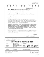
Access to the rear panel is recommended so that input and output connections can<br />
be changed conveniently, if desired. The rear panel connections are described in Table 2-1. As a<br />
reference for the rear panel connectors, see' Pigure 2-1.<br />
NOTE<br />
Before applying power to the unit, verify that<br />
the selected line voltage for the system matches<br />
the utiliz~d line voltage.<br />
2.2.1 CONNECTOR SIGNALS<br />
2.2.1.1 Power Input (PLIJI) - The power input connector provides the ac power input to<br />
the signal monitor. It will support line voltages <strong>of</strong> 115 Vac or 230 Vac as determined by the<br />
setting <strong>of</strong> the line voltage selector switch (52). In either pOsition, the power line frequency may<br />
range from 48 - 420 Hz.<br />
2.2.1.2 Line Puse (PU - The line fuse and fuse housing provide a 3/4 amp slo-blow fuse for<br />
115 Vac or a 3/8 amp slo-blow fuse for 230 Vac power input. .<br />
2.2.1.3 X-Y Input/Output (JI) - This 9-socket D-type connector provides for the X and Y<br />
axis <strong>of</strong> the signal monitor display to be connected to an external monitor. It also permits using<br />
the <strong>WJ</strong>-<strong>9205</strong> as an X-Y <strong>Moni</strong>tor with an external X-Y Input Source, such as a <strong>WJ</strong>-9206 Signal<br />
<strong>Moni</strong>tor or a <strong>WJ</strong>-8611B Receiver with the signal monitoroption (Option A) installed.<br />
2-1
<strong>WJ</strong>-<strong>9205</strong><br />
INSTALLATION AND OPERATION<br />
Table 2-1. Table <strong>of</strong> Connectors<br />
Connector Type Function<br />
FLIJI Power Input 3 Prong Power Input 115/230 Vac ±1096, 48 - 420 Hz<br />
Fl Fuse Slo-Blow Houses 3/4 amp for 115 Yac or 3/8 amp for<br />
230 Vac<br />
Jl X-YIN/OUT 9 Pin 0 Connects X and Y axis <strong>of</strong> the Signal <strong>Moni</strong>tor<br />
display to an external monitor. .<br />
·J2 Interface RCVR #1 15 Pin 0 Interface Connector for Receiver #1<br />
J3 Interface RCVR #2 15 Pin 0 Interface Connector for Receiver #2<br />
J4 InterfaceRCVR #3 15 Pin 0 Interface Connector for Receiver #3<br />
J5 Remote <strong>Control</strong> IEEE-488 Remote <strong>Control</strong> Port (Optional)<br />
J6 Serial Data Port RS-232 or RS-422 Future expandability. (Not presently used.)<br />
AIA7Jl IF IN RCVR #1 BNC Provides 50 ohm input to a 21.4 MHz IF<br />
signal from Receiver #1<br />
AIA7J2 IF IN RCVR #2 BNC Provides 50 ohm input to a 21.4 MHz IF<br />
signal from Receiver '2<br />
AIA7J3 IF IN RCVR #3 BNC Provides 50 ohm input to a 21.4 MHz IF<br />
signal from Receiver #3<br />
A1A7<br />
J2 J3 J4<br />
®<br />
J1<br />
0<br />
~ ~<br />
3/4 A S8 115 VAC<br />
318 A 58230 VAC<br />
® • 0 Fl 52<br />
A1A7 0<br />
@<br />
J2<br />
0<br />
•• 0<br />
(J6) .<br />
0<br />
~230V<br />
0 Cl l15V<br />
0<br />
®<br />
AlA7<br />
0<br />
• 0<br />
J3 ••• • • • •<br />
FUJ1<br />
Jl<br />
@<br />
(j)<br />
...<br />
(§. GNO<br />
~ I~<br />
0 I I I I<br />
Figure 2-1. <strong>WJ</strong>-<strong>9205</strong> Signal <strong>Moni</strong>tor, aew Panel ConnectorS<br />
2-2
INSTALLATION AND OPERATION<br />
<strong>WJ</strong>-<strong>9205</strong><br />
2.2.1.4 Receiver 11 Interface Connector (J2) - This 15-pin D-type connector is used to<br />
connect Receiver #1 to the Signal <strong>Moni</strong>tor when Receiver #1 is a <strong>WJ</strong>-8615D Receiver whose<br />
frequency range has been extended to 500 MHz. Figure 2-1 depicts the pin configuration. As<br />
shown, pin 1 is the bottom pin <strong>of</strong> the left column and pin 9 is the bottom pin <strong>of</strong> the right column.<br />
Pin 6 accepts a HIGH or LOW TTL signal. Pin 2 is ground. See paragraph 1.4.<br />
2.2.1.5 Receiver 12 Interface Connector (J3) - This IS-pin D-type connector is used to<br />
connect Receiver #2 to the Signal <strong>Moni</strong>tor when Receiver #2 is a <strong>WJ</strong>-8615D Receiver whose<br />
frequency range has been extended to 500 MHz. Figure 2-1 depicts the pin configuration. As<br />
shown, pin 1 is the bottom pin <strong>of</strong> the left column and pin 9 is the bottom pin <strong>of</strong> the right column.<br />
Pin 6 accepts a HIGH or LOW TTL signal. Pin 2 is ground. See paragraph 1.4.<br />
2.2.1.6 Receiver '3 Interface Connector (J4) - This 15-pin D-type connector is used to<br />
connect Receiver #3 to the Signal <strong>Moni</strong>tor when Receiver #3 is a <strong>WJ</strong>-8615D Receiver whose<br />
frequency range has been extended to 500 MHz. Figure 2-1 depicts the pin configuration. As<br />
shown, pin 1 is the bottom pin <strong>of</strong> the left column and pin 9 is the bottom pin <strong>of</strong> the right column.<br />
Pin 6 accepts a HIGH or LOW TTL signal. Pin 2 is ground. See paragraph 1.4.<br />
2.2.1.7 Remote <strong>Control</strong> (J5) (Optional) - This IEEE-488 type multipin connector provides<br />
the control interfacing between the <strong>WJ</strong>-<strong>9205</strong> Signal <strong>Moni</strong>tor and a suitable external computer or<br />
other remote controlling device using a standard IEEE-488-1978 remote interface. The<br />
installation <strong>of</strong> the interface cables at this connector must comply with the specifications set<br />
forth by the IEEE-488-1978 Standard, as deviation from this standard could result in unreliable<br />
bus operation.· The interface connection may be installed in a STAR or DAISY CHAIN<br />
configuration.<br />
2.2.1.8 Serial Data Port (J6) (Optional) - The RS-232 or RS-422 Port slot is available on<br />
the rear panel to provide for future expandability <strong>of</strong> the <strong>WJ</strong>-<strong>9205</strong> Signal <strong>Moni</strong>tor. This port is not<br />
presently supported by the standard Signal <strong>Moni</strong>tor and requires additional s<strong>of</strong>tware to be<br />
installed for it to be utilized~ This option may be included at the time <strong>of</strong> purchase or the<br />
connector and required s<strong>of</strong>tware can be installed later.<br />
2.2.1.9 Receiver 11 IN (A1A1Jl) - This BNC type connector provides a 50 ohm input<br />
impedance to a 21.4 MHz IF signal from Receiver #1, and is selected by pressing the INPUT up<br />
arrow or down arrow key on the front panel to display RXI in the window.<br />
2.2.1.10 Receiver '2 IN (A1A1J2) - This BNC type connector provides a 50 ohm input<br />
impedance to a 21.4 MHz IF signal from Receiver #2, and is selected by pressing the front panel<br />
INPUT up arrow or down arrow key to display RX2 in the window. .<br />
2.2.1.11 Receiver 13 IN (A1A1J3) - This BNe type connector provides a 50 ohm input<br />
impedance to a 21.4 MHz IF signal from Receiver #3, and is selected by pressing the INPUT up<br />
arrow or down arrow key on the front panel to display RX3 in the window.<br />
2-3
<strong>WJ</strong>-<strong>9205</strong><br />
INSTALLATION AND OPERATION<br />
2.3 EQUIPMENT MALFUNCTIONS<br />
The <strong>WJ</strong>-<strong>9205</strong> Signal <strong>Moni</strong>tor was thoroughly inspected, tested, and factory adjusted<br />
for optimum performance prior to shipment. If any malfunctions are encountered after following<br />
the recommended installation procedures, paragraph 2.2, verify that the inter-unit cables are<br />
installed properly and that the correct input signals are present at the proper jacks. Maintenance<br />
and troubleshooting <strong>of</strong> the unit can be aided utilizing the procedures outlined in Section IV <strong>of</strong> this<br />
manual. Contact your Watkins-:Johnson representative or the Watkins-Johnson Company,<br />
Communication Electronics Technology Division, Gaithersburg, Maryland prior to undertaking any<br />
corrective maintenance action, to prevent the possibility <strong>of</strong> voiding the warranty.<br />
2.4 OPERATION<br />
The <strong>WJ</strong>-<strong>9205</strong> Signal <strong>Moni</strong>tor provides a visual indication <strong>of</strong> spectrum for the<br />
21.4 MHz IF signals from one, two or three separate receivers simultaneously on its 4.0 inch<br />
(diagonal) CRT. Operation is controllable from the front panel controls or via its IEEE-488<br />
remote interface and a suitable controller. The various switches, controls and indicators used on<br />
the monitor during local operatiOn are discussed in the following paragraphs. Table 2-2 lists the<br />
controls and indicators. With the exception <strong>of</strong> the ac input voltage selector switch, all controls<br />
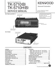
and indicators are on the front panel <strong>of</strong> the unit. See Figure 2-2 as a reference for the location<br />
<strong>of</strong> the front panel controls and indicators.<br />
Table 2-2. Table <strong>of</strong> <strong>Control</strong>s and Indicators<br />
<strong>Control</strong>/Indicator<br />
Description<br />
<strong>Control</strong>s<br />
POWE,R ••••••••••••••••••••••••.•<br />
INTE-NSITY ..•••.•...<br />
TRACE .........••...•.•.••.•.••<br />
INPUT<br />
SPAN<br />
RBW<br />
ATTEN<br />
PRESET<br />
STORE<br />
SHIFT.<br />
................~.....'....<br />
Voltage Selector (S2)<br />
Applies power to the Signal <strong>Moni</strong>tor.<br />
Adjust CRT Trace Brightness.<br />
Selects Trace number 1, 2 or 3.<br />
Selects input source: Receiver #1, Receiver #2,<br />
Receiver #3, Memory, X-Y or turns the trace<br />
<strong>of</strong>f.<br />
Selects the Frequency Span. (0 to 5 MHz in<br />
1-:2-5 sequence.)<br />
Selects 10 kHz Resolution Bandwidth or second<br />
other optional resolution Bandwidth.<br />
Selects the amount <strong>of</strong> attenuation.<br />
,Recalls previously stored parameters.<br />
Stores in memory the present displayed<br />
parameters and the associated image.<br />
Redefines the keypad for special functions. See<br />
~h2.4.1.10.<br />
Located on the rear panel, selects either 115<br />
Vac or 230 Vac Input.<br />
2-4
INSTALLATION AND OPERATION<br />
<strong>WJ</strong>-<strong>9205</strong><br />
Table 2-2. Table <strong>of</strong> <strong>Control</strong>s and Indicators (Continued)<br />
<strong>Control</strong>/Indicator<br />
Description<br />
Indicators<br />
Digital Display •...•••••••••••••••• These LEDs display the selected parameters:<br />
Trace, Input, Span, RBW and Attenuation. In<br />
addition, they indicate failure conditions•<br />
. SHIFT •••••••••••••••••••••••••• This LED indicates that the SHIFT key has been<br />
pressed to enable shifted functions, refer to<br />
paragraph 2.4.1.10 for a description <strong>of</strong> these<br />
functions.<br />
REM ••••..•••..•••••••••••••••• This LED indicates when unit is in remote<br />
control. Remote control is selected by pressing<br />
the SHIFT key and then pressing the STORE<br />
key. Refer to paragraph 2.4.1.10.<br />
@<br />
- -<br />
-j l-<br />
i \'<br />
--'-<br />
rt -<br />
-f-<br />
- f-<br />
@<br />
@@rrl:t===:==@=l:t====@=U===~~~~l<br />
( 2 R XI 2. M 10K 4 0 )<br />
@<br />
@<br />
TRACE I NPUT SPAN R8W ATTEN<br />
mmmmm<br />
o I 234<br />
[!J [!J [!J [!J m<br />
u A·<br />
5 6£\71\8 9<br />
"SHIFT., REM<br />
~aaB<br />
8 C<br />
INTENSITY ® ®<br />
•<br />
POWER<br />
Figure 2-2. <strong>WJ</strong>-<strong>9205</strong> Signal <strong>Moni</strong>tor, Front Panel <strong>Control</strong>s and Indicators<br />
2-5
<strong>WJ</strong>-<strong>9205</strong><br />
INSTALLATION AND OPERATION<br />
2.4.1<br />
CONTROLS AND INDICATORS (STANDARD LOCAL OPERATION)<br />
The keyboard consists <strong>of</strong> ten buttons labeled 0 to 9, as shown in Figure 2-2. Buttons<br />
o to 4 have up arrows imprinted on them, while buttons 5 t09 have down arrows. Each button<br />
pair (0-5, 1-6, 2-7, 3-8, 4~9) causes the value in the display directly above the buttons to cycle<br />
either up or down the number <strong>of</strong> times the button is pressed. The top buttons (0 to 4) cause the<br />
number to get larger or the display to cycle up. The bottom buttons (5 to 9) cause the number to<br />
get smaller or the display to cycle down.<br />
When the button being pressed causes the data being displayed to reach its limit<br />
(either up or down), pressing the button any further does not" effect the display, but causes an<br />
audible tone.<br />
2.4.1.1 Push On/Off POWER Switch - This pushbutton switch applies power to the unit.<br />
Pressing the button a second time removes the power from the unit.<br />
During the power up sequence, pressing the A or B pushbutton allows the unit to<br />
respectively perform the IEEE-488 address check (if installed), or set the default parameters<br />
listed in paragraph 2.4.1.8. These functions can be selected by pressing the pushbutton for the<br />
desired operation during the power up sequence.<br />
A - Pressing this pushbutton during the signal monitor power up<br />
sequence enables the IEEE-488 address to be viewed or changed. When<br />
enabled, the IEEE-488 address is visible on the signal monitor front<br />
panel display as: 488 ADR XX .DCML (XX=OO to 31). With this<br />
displayed on the front panel, pressing any two numbers changes the 488<br />
address to the value <strong>of</strong> the new number. Pressing a third digit allows<br />
the new 488 address to be changed again. Pressing the A (PRESET)<br />
pushbutton enters the displayed 488 address as the signal monitor<br />
IEEE~488 address. If an invalid 488 address is selected, pressing the A<br />
key sets the 488 address to 01.<br />
B - Pressing this key in during the power up sequence sets the signal<br />
monitor operating parameters to the default parameters. This allows<br />
signal monitor parameters to be set to known conditions. Refer to<br />
p~agraph 2.4.1.8 for a listing <strong>of</strong> the default parameters. This can be<br />
useful in the event the signal monitor operation latches up.<br />
Pressing the power ON/OFF button a second time removes the power from the unit<br />
and the button returns to the fully extended OFF position.<br />
2.4.1.2 INTENSITY <strong>Control</strong> - This control is used to adjust the intensity or brightness <strong>of</strong><br />
the trace(s} on the front <strong>of</strong> the CRT. The INTENSITY may be adjusted to suit the operator.<br />
2.4.1.3 TRACE <strong>Control</strong> - The TRACE control pushbuttons allow selection <strong>of</strong> 1, 2 or 3<br />
Trace(s} to be displayed on the CRT. The vertical space on the CRT is divided evenly by the<br />
number <strong>of</strong> traces selected to be displayed. A single trace occupies the full screen and is<br />
calibrated with a gradicule. Selection <strong>of</strong> two or three traces respectively occupies 1/2 and 1/3<br />
screen displays on the CRT. Refer to Figure 2~3 for the CRT display for the different number <strong>of</strong><br />
traces.<br />
2-6
INSTALLATION AND OPERATION<br />
<strong>WJ</strong>-<strong>9205</strong><br />
One Trace<br />
Two Traces<br />
Three Traces<br />
Figure 2-3. CRT Displays forDifferent Traces<br />
2-7
<strong>WJ</strong>-<strong>9205</strong><br />
INSTALLATION AND OPERATION<br />
Pressing the TRACE up arrow or down arrow keys enters the value 1, 2 or 3 in the<br />
display window. During keyboard control, the number displayed in the trace position is the trace<br />
to which the keyboard operation applies. For each trace selected, signal source (INPUT),<br />
frequency span (SPAN), display resolution (RBW) and signal attenuation (ATTEN) are individually<br />
programmed.<br />
When any <strong>of</strong> the traces are assigned to the X-Y signal sourcing input<br />
(paragraph 2.4.1.4), then the entire CRT is devoted to the X-Y signal input.<br />
2.4.1.4 INPUT Selector - The INPUT selector pushbuttons are used to select the receiver<br />
IF signal(s) source for the trace indicated in the display window,from up to three (3) receivers.<br />
Each trace may be individually programmed for INPUT. By pressing the INPUT up arrow or down<br />
arrow keys, the INPUT display window indicates the signal source for the trace displayed on the<br />
CRT. The selections <strong>of</strong> INPUT available and a brief description <strong>of</strong> each follow:<br />
RX1 -<br />
RX2 -<br />
RX3 -<br />
IF Signal from Receiver #1 is selected.<br />
IF Signal from Receiver #2 is selected.<br />
IF Signal from Receiver #3 is selected.<br />
M-Z - Stored Frame <strong>of</strong> Data in memory is selected. When in M-Z<br />
mode for INPUT, the display will present the parameters under which<br />
the data was captured, INPUT, SPAN, RBW, and ATTEN. The trace<br />
display window will indicate which trace is displaying the M-Z data.<br />
X-Y - CRT deflection is sourced to the X-Y Signal Inputs. When the<br />
X-Y mode is selected, the display will ignore the arrangement <strong>of</strong><br />
display fields, and shall read "X-Y SCOPE". All internal functions <strong>of</strong><br />
the signal monitor stop except for error checking. The TRACE, SPAN,<br />
RBW and ATTEN keys have no effect. To exit 'X-Y SCOPE' mode,<br />
either <strong>of</strong> the INPUT keys must be pressed. Pressing the PRESET key<br />
will cause the normal preset function and exit the X-Y mode. The .unit<br />
can be put in remote control by the IEEE-488 bus even if 'X-Y SCOPE'·<br />
has been selected•<br />
. OFF - Trace not displayed.<br />
2.4.1.5 SPAN <strong>Control</strong> - The SPAN control pushbuttons are used to select the· frequency<br />
span <strong>of</strong> the trace shown in the display window. Each trace may be individually programmed for<br />
frequency span. By pressing the SPAN up arrow or down arrow key, the width <strong>of</strong> the trace is<br />
incremented or decremented from 0 kHz to 5 MHz. The LED display window, above the keys,<br />
shows the selected frequericy span. The choices are: 000, 50 kHz, .1 MHz, .2 MHz, .5 MHz, 1.<br />
MHz, 2. MHz and 5. MHz. Choosing a span <strong>of</strong> 000 provides a center tuned frequency <strong>of</strong> 21.4<br />
MHz. A span <strong>of</strong> 000 can be used to observe modulation on a received signal.<br />
2-8
INSTALLATION AND OPERATION<br />
<strong>WJ</strong>-'<strong>9205</strong><br />
2.4.1.6 ROW <strong>Control</strong> - The RBW control pushbuttons are used to select the Resolution<br />
Bandwidth <strong>of</strong> the trace shown in the display· window. Each trace may be programmed<br />
individually, when the optional second ResolUtion Bandwidth has been installed, by pressing the up<br />
arrow or down arrow button to the desired selection. Without this option installed, the standard<br />
unit utilizes 10 kHz as the only selection. Pressing the increment or decrement buttons will<br />
result in an audible tone and the display will warn "OPTION NOT INST".<br />
2.4.1.7 ATTENuation Selector - The Attenuation selector pushbuttons provide attenuation<br />
<strong>of</strong> incoming signals in 10 dB steps. Each trace may be individually programmed for the level <strong>of</strong><br />
attenuation. By pressing the ATTEN up arrow or down arrow key, the attenuation <strong>of</strong> the signal is<br />
incremented or decremented in 10 dB steps. The LED display window, directly above the keys,<br />
displays the selected level <strong>of</strong> attenuation. The attenuation: range available is: 0 dB,lO dB, 20<br />
dB; 30 dB, 40 dB, 50 dB, 60 dB and 70 dB. Note that the attenuation is performed to the actual<br />
incoming signal(s), so the trace is also reduced in amplitude by the amount <strong>of</strong> attenuation<br />
selected.<br />
2.4.1.8 PRESET <strong>Control</strong> - The PRESET control button causes the signal monitor operating<br />
parameters to be reset to parameters stored in sustained memory. If no preset parameterS have<br />
been entered or if sustained memory is lost, the signal monitor will be set to the following<br />
default parameters:<br />
Single Trace<br />
Input Source<br />
Span<br />
RBW<br />
Attenuation<br />
488 Address<br />
Receiver #1<br />
5 MHz<br />
10 kHz<br />
odB<br />
Determined by switch setting<br />
To store operating parameters in memory, first set the signal monitor to the<br />
desired status. Next, press the SHIFT key and then press the PRESET key. The operating<br />
parameters present at the time the SHIFT and PRESET keys were pressed are now stored in<br />
sustained memory. This allows operating parameters to be changed and then by pressing the<br />
PRESET key to return to a known preset operating status.<br />
2.4.1.9 STORE <strong>Control</strong> - The STORE control key causes the Signal <strong>Moni</strong>tor to store the<br />
current input frame and parameters selected for the INPUT (RCVR #1, RCVR #2, or RCVR #3)<br />
from any <strong>of</strong> the three traces. This data is stored in the display memory. Only one frame and its<br />
associated parameters can be stored in memory at anyone time. When a new input is selected<br />
for memory, the memory contents are overwritten so that only the last stored seiection remains<br />
in memory. The stored frame and parameters can be recalled and displayed on any trace by<br />
selecting the M~Z INPUT.<br />
When the INPUT for a trace is switched to M-Z (where Z can be·equal to Z, 1, 2, or<br />
3), the stored input frame and parameters will be displayed. M-Z indicates that the memory has<br />
been cleared and no INPUT or parameters have been stored in memory. M-l indicates the frame<br />
and parameters stored were stored for the RCVR #1 input. M":2 indicates that the stored frame<br />
and parameters were those selected for the RCVR #2 input. M-3 indicates that the frame and<br />
parameters stored were those selected for RCVR #3.<br />
2-9
<strong>WJ</strong>-<strong>9205</strong><br />
INSTALLATION AND OPERATION<br />
2.4.1.10 SHIFT <strong>Control</strong> - The SHIFT control button is used, along with one other button, to<br />
allow additional functions to be selected. Pressing the SHIFT key illuminates the SHIFT LED on<br />
the signal monitor front panel. When this LED is illuminated, the SHIFT function is enabled.<br />
Pressing a second key enables the selected SHIFT function. After pressing the second key, the<br />
SHIFT LED is extinguished indicating that the SHIFT function has been performed. The following<br />
list describes the various SHIFT functions.<br />
SHIFT/STORE - Pressing the SHIFT key and then pressing the STORE<br />
key allows the operator to toggle between local control and remote<br />
control. When remote control is selected the REM LED illuminates. In<br />
local control, the LED is extinguished. The current control mode is<br />
maintained in battery sustained memory.<br />
SHIFT/PRESET - Pressing the SHIFT pushbutton and then pressing the<br />
PRESET pushbutton causes the current operating parameters <strong>of</strong> each<br />
trace to be stored in memory. Once stored, the parameters for each<br />
trace can be changed as desired. Then by pressing PRESET, all three<br />
signal monitor traces are set to the parameters stored in memory.<br />
SHIFT/l - Pressing the SHIFT and then the 1 pushbuttons causes the<br />
CRT to temporarily display a known test pattern on the selected trace<br />
display. The test pattern is a series <strong>of</strong> four ramp waveforms. Refer to<br />
Figure 2-4 for the ramp waveform.<br />
Figure 2-4. Test Pattern CRT Display<br />
2-10
INSTALLATION AND OPERATION<br />
<strong>WJ</strong>-<strong>9205</strong><br />
SIDFT/2 - Pressing the SHIFT and then the 2 keys cause any existing<br />
error messages to be displayed on the front panel display. An error<br />
condition is indicated on the front panel via-the presence <strong>of</strong> decimal<br />
points in place <strong>of</strong> blank spaces. The decimal points disappear when the<br />
SHIFT/2 keys are pressed and the error codes are displayed. Refer to<br />
Table 2-3 for the list <strong>of</strong> error messages. SHIFT!2 has no effect if no<br />
error conditions exist.<br />
Table 2-3. Error Messages<br />
Message<br />
DRD FAILURE<br />
-15 V LOW<br />
-15 V HIGH<br />
DA FAILURE<br />
+5 V LOW<br />
+5 V HIGH<br />
NO LOCK-VCO<br />
+8 V LOW<br />
+8 V HIGH<br />
+15 V LOW<br />
+15 V HIGH<br />
488 SELF TEST<br />
RAM FAILURE<br />
EPROM CKSUM<br />
2K V LOW<br />
-2K V HIGH<br />
OPTION NOT INST<br />
POWER UP<br />
UNKNOWN COM<br />
COM ERROR<br />
INVALID PAR<br />
Cause <strong>of</strong> Error<br />
DRD not interrupting<br />
. -15 Vdc supply voltage too low<br />
-15 Vdc supply voltage too high<br />
Data acquisition not interrupting<br />
+5 Vdc supply voltage too low<br />
+5 Vdc supply voltage too high<br />
VCO fails to lock<br />
+8 Vdc supply voltage too low<br />
+8 Vdc supply voltage too high<br />
+15 Vdc supply voltage too low<br />
+15 Vdc supply voltage too high<br />
IEEE-488 fails self test<br />
Sustained memory test failure<br />
EPROM fails checksum comparison<br />
-2K Vdc supply voltage too low<br />
-2K Vdc supply voltage too high<br />
An Option must be installed before the requested function<br />
can be performed .<br />
Power has been applied to the unit<br />
Unimplemented 488 command<br />
488 Command error<br />
Invalid 488 Request<br />
NOTE<br />
If an errorfias been sent to the display, the error<br />
message is not repeated unless the power is<br />
cycled <strong>of</strong>f and on again or unless the SHIFT/2<br />
keys are pressed. Decimal points are visible in<br />
the display until the error is cleared.<br />
2.4.1.11 Voltage Selector Switch (S2) - The voltage selector switch, located on the rear<br />
panel, permits selection <strong>of</strong> either 115 Vac or 230 Vac line voltage input. Set the voltage selector<br />
switch in the voltage position closest to the line voltage· utilized. B6th the 115 V and 230 V<br />
position will support line voltages ranging from ±10% <strong>of</strong> the stated line voltage. In either<br />
position, the power line frequency may range from 48 to 420 Hz.<br />
2-11
<strong>WJ</strong>-<strong>9205</strong><br />
INSTALLATION AND OPERATION<br />
2.4.1.12 Display -- An alphanumeric 16 character LED display provides visual indication <strong>of</strong><br />
working parameter conditions. Refer to Figure 2-2 for a typical alphanumeric display. The<br />
display is viewed through a display window which is located above the keypad on the front panel<br />
and divided into five fields. The display indicates the parameter setting: TR (Trace), INPUT,<br />
SPAN, RBW (Resolution Bandwidth), and ATTEN (Attenuation). The display is also used to<br />
display messages such as the product number, s<strong>of</strong>tware version (<strong>WJ</strong>-<strong>9205</strong>~X.X.X)and to alert the<br />
operator <strong>of</strong> failure conditions. The position <strong>of</strong> each part <strong>of</strong> the display and spacing <strong>of</strong> the display<br />
is as follows:<br />
-~b-~----b------b-~----b---<br />
TR INP SPN RBW ATN<br />
2.5 REMOTE OPERATION<br />
The IEEE-488 Remote Interface provides talk and listen capabilities between the<br />
signal monitor and external equipment, such as calculators, minicomputers or other IEEE-488<br />
equipped controlling devices. The data is transferred between units in a bit-parallel, byte-serial<br />
form, utilizing sixteen interconnection lines. These lines consist <strong>of</strong> eight bi-directional data bus<br />
lines, three data byte transfer lines and five management lines. Data or address information is<br />
transferred between devices, utilizing the data bus lines. Refer to Figure) 2-5 for the pin<br />
configuration <strong>of</strong> the standard IEEE-488 Data Bus.<br />
0101<br />
0102<br />
0103<br />
0104<br />
EOI<br />
DAV<br />
NRFD<br />
NOAC<br />
IFC<br />
SRQ<br />
ATN<br />
SHIELD<br />
~<br />
I 13<br />
2 14<br />
3 15<br />
4 16<br />
5 17<br />
6 18<br />
7 19<br />
8 20<br />
9 21<br />
10 22<br />
II 23<br />
12 24<br />
~<br />
0105<br />
0106<br />
0107<br />
0108<br />
REN<br />
GND ITW PAIR W!OAVI<br />
GNblTW PAIR W!NRFDI<br />
GNO ITW PAIR W!NOACI<br />
GNOITW PAIR W!IFCI<br />
GND ITW PAIR W!SRQI<br />
GND ITW PAIR W!A.... NI<br />
SIGNAL GROUND<br />
Figure 2-5. Configuration <strong>of</strong> IEEE-488 Data Bus<br />
2-12
INSTALLATION AND OPERATION<br />
<strong>WJ</strong>-<strong>9205</strong><br />
The data byte transfer lines indicate the availability and validity <strong>of</strong> the information<br />
on the data bus lines; if the devices are ready to accept data; and if the data has been accepted.<br />
The interface management lines specify whether the data bus lines are carrying data or address<br />
information; request service; clear the interface; and indicate the end <strong>of</strong> a transfer sequence.<br />
The capabilities <strong>of</strong> the IEEE-488 Interface include:<br />
Function Description<br />
• Source handshake<br />
• Acceptor handshake<br />
• Basic talker with serial poll<br />
• Basic listener with serial poll<br />
• Service request<br />
• Device clear<br />
IEEE-488-1978 Subsets<br />
(SRI)<br />
(ARI)<br />
(T6)<br />
(L4)<br />
(SRI)<br />
(DCI)<br />
Essentially, this means that the monitor can talk or listen when commanded by the controller. It<br />
can also issue a service request notifying the controller when it needs service.<br />
Two types <strong>of</strong> data transfer are supported on the <strong>WJ</strong>-<strong>9205</strong> Signal <strong>Moni</strong>tor. One type<br />
<strong>of</strong> data transfer on the IEEE-488 interface bus is ASCII. This type <strong>of</strong> transfer utilizes ASCII<br />
mnemonics to control the monitor. The termination may be CR, LF (Carriage Return, Line Feed)<br />
or LF (Line Feed) or EOI (End or Identify) set on the last character <strong>of</strong> the transfer. These<br />
mnemonics may be strung together using a semicolon. Another type <strong>of</strong> data transfer supported<br />
by the <strong>WJ</strong>-<strong>9205</strong> Signal <strong>Moni</strong>tor is binary. This type <strong>of</strong> data transfer allows single information<br />
bytes to control the monitor. In the binary operation, a command or group <strong>of</strong> commands must<br />
end with EOI (End or Identity) set on the last byte <strong>of</strong> the command. Commands may not be<br />
strung together with a semicolon or terminated with CR (Cartiage Return) or LF (Line Feed).<br />
The ASCII operation format tends to be self..,documenting and easy to understand. Binary, on the<br />
other hand, lessens the number <strong>of</strong> bytes that must be transferred and has a faster execution<br />
speed. In the ASCII format, the message consists <strong>of</strong> a series <strong>of</strong> data bytes that form one <strong>of</strong> the<br />
mnemonics listed in Table 2-4. Each byte is one ASCII character <strong>of</strong> the mnemonic. When the<br />
mnemonic contains a variable value, the mnemonic is followed by a number representing that<br />
value. Each digit <strong>of</strong> the number is applied as a separate ASCII character. In the binary format,<br />
the mnemonic is one 8-bit byte containing the hexadecimal code corresponding to the mnemonic.<br />
When a. variable value is to be included in the message, it is sent as one or more additional data<br />
bytes, representing the binary or hexadecimal value. During ASCII operation, only ASCII<br />
commands are valid and only ASCII responses are returned. In binary operation, only binary<br />
commands are valid and only binary responses are returned.<br />
2.5.1 GENERAL DESCRIPTION<br />
The command columns <strong>of</strong> Table 2-4 depict messages that. can be sent to the<br />
<strong>WJ</strong>-<strong>9205</strong> Signal <strong>Moni</strong>tor as an active listener. Responses are messages returned when the monitor<br />
is an active talker. ASCII messages may be sent with embedded spaces or any combination <strong>of</strong><br />
upper and lower case characters. In the binary mode, no blanks are allowed in the binary<br />
message. The system starts in ASCII mode and enters the binary mode by the receipt <strong>of</strong> the BIN<br />
command. The binary command 55 (REX) (85 decimal) returns the system to the ASCII mode <strong>of</strong><br />
operation.<br />
2-13
<strong>WJ</strong>-<strong>9205</strong><br />
INSTALLATION AND OPERATION<br />
In addition to the mnemonics, the monitor responds to the 488 defined commands <strong>of</strong><br />
'SDC (selected device clear) and DCL (device clear). These commands cause the monitor to do a<br />
power up reset, inclUding clearing the message buffers and sending an SRQ.<br />
Table 2-4. Remote Mnemonics<br />
Command Response Description<br />
ASCII HEX DEC ASCII HEX DEC<br />
ATT(a)<br />
ATT? 80<br />
BW(a)<br />
BW?<br />
BWC?<br />
CLH<br />
CLR<br />
ERR?<br />
HER?<br />
INP(a)<br />
INP?<br />
LLO<br />
LLO/<br />
LLO?<br />
7E(b)<br />
4E(b)<br />
9E<br />
9E<br />
CO<br />
51<br />
65(b)<br />
C3<br />
4B(b)<br />
4D<br />
F9<br />
FA<br />
FB<br />
78(b)<br />
.80<br />
158<br />
192<br />
81<br />
101<br />
195<br />
75<br />
77<br />
249<br />
250<br />
251<br />
ATT(a)<br />
BW(a)<br />
BWC(c)<br />
ERR(a)<br />
HER(aaaa)<br />
INP(a)<br />
LLO<br />
LLO/<br />
7E(b)<br />
4E(b)<br />
9E(bb)<br />
65(b)<br />
C3(bbbb)<br />
4B(b)<br />
F9<br />
FA<br />
78(b)<br />
158(bb)<br />
101(b)<br />
195(bbbb)<br />
249<br />
250<br />
Selects the input attenuation<br />
in 10 dB increments (0-7).<br />
Requests the input attenuation<br />
setting returns 0-7 for<br />
XO-70 dB <strong>of</strong> attenuation.<br />
Selects the bandwidth slot<br />
(1-8).<br />
Requests the selected bandwidth<br />
slot (1-8).<br />
Requests the selected bandwidth<br />
size. ASCII returns are<br />
up to 4 digits max (in kHz),<br />
9999 is the highest value and<br />
represents 9.9 MHz. Binary<br />
returns a 2-byte binary number(in<br />
kHz) with 65536 kHz<br />
as the highest value and<br />
represents 65 MHz.<br />
Re-enables reporting <strong>of</strong> hardware<br />
error(s) previously reported.<br />
Select the default parameters,<br />
clears display RAM,<br />
clears program RAM, does not<br />
issue an SRQ.<br />
Requests the remote interface<br />
error.<br />
Requests the hardware error.<br />
Selects the input source .<br />
1-3= receiver inpt,lts<br />
4 = memory<br />
8 = X-y<br />
o = no input selected (<strong>of</strong>f)<br />
Requests the selected input<br />
source.<br />
Selects local lockout.<br />
Returns to local control mode.<br />
Requests lockout status.<br />
In local lockout.<br />
In local control.<br />
2-14
INSTALLATION AND OPERATION<br />
<strong>WJ</strong>-<strong>9205</strong><br />
Table 2-4. Remote Mnemonics (Continued)<br />
Command Response Description<br />
ASCII HEX DEC ASCII HEX DEC<br />
MSK(b) BD(b) 189 Sets the device status mask. Each<br />
status byte bit may be masked <strong>of</strong>f<br />
separately by writing a binary "1"<br />
in the corresponding location.<br />
Bit<br />
D7 Not Used<br />
D6 SRQ<br />
D5 Command Error<br />
(ERR 23)<br />
D4 Not Used<br />
D3 Operation or<br />
Mode Change<br />
D2 Hardware Error<br />
D1 Power Up<br />
DO Not Used<br />
RMT 81 129 Selects remote control mode.<br />
RMT/ 82 130 Selects local control mode.<br />
RMT? 83 131<br />
RMT 81 129<br />
Requests control mode.<br />
In remote mode.<br />
SP(a) BA 186<br />
RMT/ 82 130 In local mode.<br />
Selects the span (0-7)<br />
SP? BC 188 SP(a) BC(b) 186(b) span width<br />
MHz = nnnM<br />
0<br />
Requests<br />
= autocenter<br />
the selected<br />
kHz = nnnK<br />
STS? 92 146 STS(a) 92(b) 146(b) Requests device status<br />
0<br />
1 = power up<br />
2 = hardware error<br />
3 = remote interface error<br />
4 = busy<br />
5 = busy<br />
6 = SRQ set by this unit<br />
STY(a) C5 197 Stores selected trace to memory<br />
TRC(a) OC(b) 12 Selects the trace II (1-3).<br />
TRC? OE 14 Requests the trace #.<br />
TRC(a) OC(b) 12<br />
VER? 0 0 Requests equipment type and<br />
s<strong>of</strong>tware revision level.<br />
VER<br />
<strong>9205</strong> -X.X.X<br />
!IIUT~:::i: a = ASCll number followed by a delImiter<br />
b =<br />
c =<br />
s =<br />
a single Binary number<br />
4 bytes <strong>of</strong> ASCII data representing a number<br />
a string <strong>of</strong> messages separated by ; in response to a single query<br />
2-15
<strong>WJ</strong>-<strong>9205</strong><br />
INSTALLATION AND OPERATION<br />
2.6<br />
ERRORS<br />
2.6.1<br />
LOCAL OPERATION<br />
Should an error occur that is associated with the signal monitor during local<br />
operation, the display window will indicate the last error condition that has been reported. A ht<br />
<strong>of</strong> the error numbers, conditions and display messages are found in Table 2-3. Pressing the SHliT<br />
key and then pressing the 2 key causes the last error condition to be displayed. Pressing these<br />
two keys until no more errors are displayed, clears the error buffer and returns the signal monitor<br />
display to' normal. .<br />
2.6.2 REMOTE OPERATION<br />
During remote operation, errors are identified when either the ERR? or HER?<br />
query is sent. The ERR? query requests the signal monitor to send the status <strong>of</strong> the last remote<br />
or communication error. The signal monitor responds with an error response as: ERR X<br />
(X = 1- 7). The value <strong>of</strong> X is as follows:<br />
Cause <strong>of</strong> Error<br />
1<br />
4<br />
6<br />
7<br />
Input buffer over run<br />
Invalid argument or Out <strong>of</strong> range<br />
"?" or "I" invalid for command<br />
Invalid mnemonic or binary command<br />
The response to the hardware error query (HER?) uses the following- format: HER<br />
Xl, X2, X3, X4. Where X is a decimal value (0-255) <strong>of</strong> a binary code. The following list indicates<br />
the byte, bit value, and corresponding error condition.<br />
Byte Xl<br />
Bit Value Error Condition<br />
0 1 DRD Failure<br />
1 2 15V Line Low<br />
2 4 15V Line High<br />
3 8 DA Failure<br />
4 16 5V Line Low<br />
5 32 5V Line High<br />
6 64 VCO Unlocked<br />
7 128 +8V Line Low<br />
2-16
INSTALLATION AND OPERATION<br />
<strong>WJ</strong>-<strong>9205</strong><br />
Byte X2<br />
o<br />
1<br />
2<br />
3<br />
4<br />
5<br />
6<br />
7<br />
1<br />
2<br />
4<br />
8<br />
16<br />
32<br />
64<br />
128<br />
.Error Condition<br />
+8V Line High<br />
+15V Line Low<br />
+15V Line High<br />
UART Self-test Failed<br />
488 Self-test Failed<br />
Not Used<br />
RAM Failure<br />
PROM Checksum Failed<br />
Byte X3<br />
o<br />
1<br />
2<br />
3<br />
4<br />
5<br />
6<br />
7<br />
1<br />
2<br />
4<br />
8<br />
16<br />
32<br />
64<br />
128<br />
Error Condition<br />
-2kV Line Low<br />
-2kV Line High<br />
Option Not Installed<br />
S<strong>of</strong>tware Failure<br />
Not Used<br />
Not Used<br />
488 Execution Error<br />
488 Command Error<br />
Byte X4<br />
o<br />
1<br />
2<br />
3<br />
4<br />
5<br />
6<br />
7<br />
1<br />
2<br />
4<br />
8<br />
16<br />
32<br />
64<br />
128<br />
Error Condition<br />
488 Invalid Request<br />
(Bits 1-7 are not<br />
presently used.)<br />
2.7 PREPARATION FOR RESHIPMENT<br />
If the unit must be prepared for reshipment, the packaging methods should follow<br />
the pattern established in the original shipment. If retained, the original materials can be reused<br />
to a large extent, or at least provide guidance for the repackaging effort.<br />
2-17
SECTIONm<br />
CIRCUIT DESCRIPTION
<strong>WJ</strong>..,<strong>9205</strong><br />
CIRCUIT DESCRIPTION<br />
SECTION ill<br />
CIRCUIT DESCRIPTION<br />
3.1 GENERAL<br />
The <strong>WJ</strong>-<strong>9205</strong> Signal <strong>Moni</strong>tor is a multi-trace, microprocessor-controlled signal<br />
monitor. The <strong>WJ</strong>-<strong>9205</strong> provides from one to three signal traces with selectable resolution<br />
bandwidths. Signal activity displayed on the signal monitor traces are automatically centered<br />
and optimized. The signal monitor circuits can be divided into three sections: the RF section,<br />
the digital section,and the power/display section. These sections are interconnected via the<br />
Motherboard assembly (At). The Motherboard provides the electrical and physical connections<br />
required for the signal monitor operation.<br />
The <strong>WJ</strong>-<strong>9205</strong> Signal <strong>Moni</strong>tor is designed to provide a signal display for up to three<br />
<strong>WJ</strong>-8615 Receivers. The following paragraphs describe the path a signal takes through the signal<br />
monitor. This signal path is shown on Figure 3-1.<br />
Received 21.4 MHz IF signals are applied to one <strong>of</strong> three BNC connectors (A1A7J1<br />
A1A7J3) on the signal monitor rear panel. These connectors provide a 50 ohm impedance for the<br />
received signals. Signals at these connectors are directed to the Input <strong>Control</strong> assembly (AlA7).<br />
Signals applied to the Input <strong>Control</strong> module are applied to the Input Select/Step Attenuator<br />
(A1A7A1). This module determines which input signal is to be processed. The selected signal can<br />
be attenuated from 0 dB to 70 dB in 10 dB steps before being applied to the Input Filter assembly<br />
(A1A7A2).<br />
Input Filter assembly (AlA7A2) provides isolation and low-pass filtering <strong>of</strong> the<br />
selected input signal. From the Input Filter assembly the signal is directed to the Frequency<br />
Converter/Sweep assembly (AlAS). The input signal is applied to J1 <strong>of</strong> the First LO/First<br />
Converter/Auto Center subassembly (A1A8A1). This subassembly mixes the RF signal from the<br />
Input Filter assembly with the 118.1 MHz First LO, producing a 96.7 MHz First IF. The First IF<br />
is bandpass filtered before being applied to the Second LO/Second Converter (A1A8A2). The<br />
Second LO/Second Converter low-pass filters the First IF signal before it is mixed with an 86<br />
MHz signal, producing the 10.7 MHz Second IF. The Second IF is applied to the Second IF/lO kHz<br />
RBW subassembly (A1A8A3). This subassembly bandpass filters the 10.7 MHz Second IF before<br />
amplifying the IF signal. After amplification, the Second IF is again bandpass filtered, providing<br />
the video resolution bandwidth before being directed to the LOG IF Amplifier/Detector (A1AIO).<br />
Post filtered 10.7 MHz Second IF signals are low-pass filtered before being buffered and applied<br />
to the successive detector network. The output <strong>of</strong> the Successive detector network is amplified<br />
and applied to the LOG amplifier. The output voltage (0 to 5 Vdc) is applied to the display<br />
section to provide the vertical deflection for the CRT.<br />
<strong>Control</strong> <strong>of</strong> the signal monitor operation is provided via the digital section. The<br />
digital section contains the operating program, the microprocessor, and the display memory<br />
storage. The Microprocessor assembly (A1A1) contains the operating program (stored in<br />
EPROM), the microprocessor and the bus controller devices. The microprocessor controls the<br />
signal monitor operation using the operating program stored in EPROM. The Operating status <strong>of</strong><br />
the signal monitor is stored in RAM. Timing for signal monitor operations is provided by the<br />
Microprocessor assembly. Data to and from the Microprocessor assembly pass through the<br />
Input/Output assembly (A1A4). Front panel control data, display data, synthesizer data, resolution<br />
bandwidth data, input selection, and attenuation selection all pass through the Input/Output<br />
assembly. Data is directed through the Input/Output module to the proper assembly.<br />
3-1
CIRCUIT DESCRIPTION<br />
<strong>WJ</strong>-<strong>9205</strong><br />
The Data Acquisition assembly (A1A2) provides the 1024 data points the signal<br />
monitor uses to produce the video trace. The signal level at each <strong>of</strong> the 1024 data points is<br />
determined and converted from an analog level to a digital word and stored in the DRD (digjtally<br />
refreshed display) memory. Digital Refreshed/Display Timing <strong>Control</strong> assembly (A1A3) stores<br />
1024 discrete data points in memory. These data points are used to produce the video display.<br />
The High Voltage Power Supply/Video assembly (A2) provides the voltages required<br />
to operate the CRT (cathode ray tube). Voltages provided by the High Voltage Power Supply<br />
include the filament voltage, the cathode voltage, the accelerator voltage, the high voltage<br />
sample voltage, and the horizontal and vertical voltages.<br />
The Low Voltage Power Supply (A3) provides the supply voltages used by the other<br />
signal monitor assemblies.<br />
I<br />
+2dB<br />
-.5 dB<br />
-6dB<br />
96.7MHZ<br />
. +t2.5dB<br />
-4dB<br />
IO.7MHZ:<br />
I<br />
-6dB<br />
I<br />
III<br />
I<br />
IIIIIIII<br />
-.j dB +14dB 60dB<br />
RANGE<br />
J2<br />
J3<br />
AIA7AI<br />
I. II<br />
AIA1A2<br />
41A8AI<br />
AIA8<br />
AIA8A2<br />
AIA8A3 : AtA,O<br />
Figure 3-1. <strong>WJ</strong>-<strong>9205</strong> Signal Flow Block Diagram<br />
3.2 DETAILED CIRCUIT DESCRIPTION<br />
3.2.1 TYPE 796534-1 MICROPROCESSOR (AlAI)<br />
Refer to Figure 6-2 for the Type 795634-1 schematic diagram. The reference<br />
designation for the Microprocessor module is AlAI. Refer to Figure 3-2 for the Microprocessor<br />
block diagram.<br />
The Microprocessor module (AlAI) contains the signal monitor operating s<strong>of</strong>tware,<br />
the memory storage, and the s<strong>of</strong>tware program for the signal monitor operation. Microprocessor<br />
US controls the operation <strong>of</strong> the signal monitor via the address bus lines (AO-A15) and the data<br />
bus lines (DI/OO-DI!07). Using the address lines, the microprocessor selects one device on the<br />
bus to receive data from (read) or send data to (write). This allows the microprocessor to control<br />
the signal monitor operations. The logic level <strong>of</strong> the microprocessor read/write line (pin 36)<br />
determines whether the device addressed is written to or read from. When this line is High, the<br />
selected device is read from and when the line is Low, the device is written to. The<br />
microprocessor internally divides the 5.24 MHz oscillator frequency by four, producing a clock<br />
3-2
<strong>WJ</strong>-<strong>9205</strong> CIRCUIT DESCRIPTION .<br />
frequency <strong>of</strong> 1.31 MHz. Two clock outputs are provided from the microprocessor" ~he quadrature<br />
clock (Q) arid the enable clock (E). These clocks are used to establish and synchronizfa timing<br />
throughout the signal monitor circuits•<br />
..-------.E<br />
.-----.0<br />
_.....................,<br />
.---~--~-~-----------------~~~__l<br />
•. RJIN<br />
OSC J----......,-t<br />
Y1<br />
MICRO<br />
PROCESSOR<br />
U8<br />
HEADER<br />
U7<br />
ADDRESS BUS<br />
DATA<br />
BUS<br />
XCVR<br />
U14<br />
POWER<br />
ON/FAil<br />
01-03<br />
CR1-CR3··<br />
U11<br />
RAM<br />
U5<br />
INTERRUPTS<br />
ADDRESS<br />
BUS<br />
U14<br />
ONE SHOT<br />
U19<br />
ADDRESS<br />
DECODER<br />
U16<br />
MWAIT<br />
Figure 3-2. Microprocessor Block Diagram<br />
The signal monitor operating program· is contained in Erasable Programmable Read<br />
Only Memory (EPROM) U1. This device contains the operating s<strong>of</strong>tware used to control the<br />
signal monitor operation. Random Access Memory (RAM) U5 stores the current signal monitor<br />
operating status. It also maintains the signal monitor operating status present at the time power<br />
is turned <strong>of</strong>f. RAM memory is maintained viaback-up battery BTl and its associated circuitry.<br />
3-3
CIRCUIT DESCRIPTION<br />
<strong>WJ</strong>-<strong>9205</strong><br />
When power is turned <strong>of</strong>f, the +5 Vdc supply voltage drops below the accepted level.<br />
The change in voltage is sensed by the" power up/down circuit (Ql..,Q3, CRI-CR3, Ull, and their<br />
associated components). When the supply voltage drops below the level established by R7, the<br />
power up/down circuit forces the output <strong>of</strong> UllE and UllF Low. This Low is applied to the NMI<br />
(non-maskable interrupt) and the RESET lines <strong>of</strong> microprocessorU8, halting its operation. This<br />
same Low is also directed to jumperwires JW5-JW7, to place the device installed in the<br />
associated socket in a high impedance state. With these devices disabled, the +2.8 Vdc back-up<br />
battery voltage is directed to the installed memory device via jumperwires JWI-JW3. The backup<br />
battery is used to maintain the data stored in these inemory devices while power is <strong>of</strong>f.<br />
When power is restored to the signal monitor, the output from UllE and UllF is<br />
forced High and the microprocessor resumes normal operation. The data stored in the RAM<br />
device i~ accessed by the microprocessor, returning the signal monitor to the operating parameterspresent<br />
at the time <strong>of</strong> power interruption.<br />
Microprocessor U8 useS different address locations to select the device with which<br />
the microprocessor is to communicate. Table 3-1 lists the address (in HEX format) and the<br />
device selected. Depending on the logic level <strong>of</strong> the read/write line (pin 36), the device<br />
addressed is either read from (logic High) or written to (logic Low).<br />
Table 3-1. Device Address Selection<br />
Address<br />
Device Selected<br />
EOOO-FFFF<br />
EPROM Ul<br />
COOO-DFFF<br />
U2 (SPARE)<br />
AOOO-BFFF<br />
U4 (SPARE)<br />
8000-8FFF<br />
RAM U5<br />
6000-7FFF<br />
Video RAM<br />
4000-5FFF<br />
Reserved<br />
0OOO-3FFF<br />
I/O Addresses<br />
0080-0084 ADC U15<br />
1000-1020 IEEE-488 Device<br />
Address bus lines AO-AI5 are connected to EPROM UI, RAM U5 (EPROM and"<br />
RAM), address decoder U16, and bus drivers U14 and U15. Address decoder U16 further decodes<br />
the address, allowing five address lines to select one <strong>of</strong> eight devices. Bus drivers U13-U15<br />
provide the required output level to drive the other modules connected to the address bus. The<br />
address bus lines are connected, via the Motherboard, to other modules within the signal monitor<br />
(SM). This allows the microprocessQr to communicate with the other modules, providing overall<br />
control <strong>of</strong> the signal monitor operation.<br />
3-4
<strong>WJ</strong>-<strong>9205</strong><br />
CIRCUIT DESCRIPTION<br />
Reading the following address locations, the microprocessor can determine the<br />
operating status <strong>of</strong> the signal monitor.<br />
Read Address<br />
0088<br />
0089<br />
008A<br />
Parameter Checked<br />
Keyboard Input<br />
Resolution Bandwidth<br />
Interrupt Status<br />
Using the following write addresses, the microprocessor can update the parameters<br />
located in the addressed memory location. After the microprocessor writes to the address, data<br />
can be sent to change the current parameter.<br />
Write Address<br />
0090<br />
0091<br />
0092<br />
0098<br />
0099<br />
009A<br />
009B<br />
009C<br />
009D<br />
009E<br />
0800-080C<br />
Parameter Addressed<br />
Lock/Hold<br />
Reset Clock<br />
Reset Keyboard<br />
Input Selector/Attenuator<br />
Resolution Bandwidth<br />
Synthesizer<br />
LED Display Position<br />
LED Display Data<br />
LED Display <strong>Control</strong>ler<br />
Interrupt Mask<br />
Video Display Data<br />
Inactive data and address bus lines are pulled High via pull-up resistors U3, U6, and<br />
U9. The pull-up resistors prevent the bus lines from being loaded by inactive lines.<br />
Flip-flopU19 acts as a pulse stretcher, introducing a time delay that allows the<br />
optional IEEE-488 moduie time to process data from slower devices that may be on the external<br />
IEEE-488 bus.<br />
3.2.2 TYPE 796537-1 INPUT/OUTPUT (A1A4)<br />
The reference designation for the Input/Output module (I/O) isAIA4. Refer to<br />
Figure 6-5 for the Type 796537-1 I/O module schematic diagram. Refer to Figure 3-3 for the<br />
Input/Output block diagram.<br />
Signal monitor data and control signals pass through the I/O (Input/Output) mOdule.<br />
The Input/Output module provides the interface between the different sections and modules.<br />
Signals passing through the I/O module include front panel display data, pushbutton data, address<br />
data, remote commands, interrupts, resolution bandwidth·· (RBW) data, input selection, and<br />
attenuator control. Audible beeper LSI is located on this module. The beeper produces an<br />
audible tone when an invalid parameter is attempted to be entered or when a parameter is<br />
attempted to be set beyond its limit.<br />
3-5
~<br />
I<br />
en<br />
E<br />
Ao·A 2<br />
IOEO<br />
A3.A6.<br />
TO U15<br />
BEEPER<br />
LSI<br />
ADDRESS<br />
TOU8 ADC ADDRESS ADDRESS<br />
DECODER 80-87<br />
TOU9<br />
DECODER! 9 ·97 DECODER/<br />
U14<br />
U15 DEMUX U8-U10<br />
TOU10<br />
U14<br />
88-8F<br />
• F<br />
DATA<br />
CONTROL<br />
U20<br />
(DISPLAY<br />
FRONT<br />
PANEL)<br />
DISP1<br />
DISP4<br />
D<br />
A<br />
T<br />
A<br />
B<br />
U<br />
S<br />
()-::tl<br />
()<br />
c:::-~<br />
t::l<br />
t:;j<br />
rn<br />
()<br />
::tl<br />
:;<br />
~<br />
(5<br />
Z<br />
o<br />
A<br />
T<br />
A<br />
B<br />
U<br />
S<br />
LINE<br />
DRIVER<br />
U19<br />
(KEYBOARD)<br />
LINE<br />
DRIVER<br />
U27<br />
(RBWACK)<br />
LINE<br />
DRIVER<br />
U17<br />
KEYBOARD DATA<br />
88 KEYBOARD<br />
RBW6<br />
-'---<br />
'41 ACKO-ACK6 '<br />
89<br />
8A<br />
IRQO-IRQ7<br />
RBW ACK<br />
IRQ STATUS<br />
DATA<br />
9AI LATCH<br />
U25<br />
(SYNTHESIZER)<br />
DATA<br />
, LATCH<br />
U26<br />
(RBW)<br />
,I RBWO·<br />
RBW6<br />
DO<br />
07<br />
LINE<br />
DRIVER<br />
U18<br />
(INTERRUPT)<br />
IRQ<br />
FLlP·FLOP<br />
U24<br />
(INPUT ATTN)<br />
~ : X-YENABLE<br />
INPUT (1-3)<br />
, ATTEN (0·70)<br />
Figure 3-3. Input/Output Block Diagram<br />
:s<br />
~<br />
I<br />
co<br />
too:)<br />
Q<br />
(II
<strong>WJ</strong>-<strong>9205</strong><br />
CIRCUIT DESCRIPTION<br />
Data is transferred to or from the I/O modUle via the eight data bus lines (DI/OO<br />
DI/07). Data is applied to the I/O module data bus via connector PI pins 7-14. Bi-directional<br />
data transceiver U13 provides the necessary bus drive level. The logic level <strong>of</strong> the read/write<br />
line (connector PI pin 36) determines the direction <strong>of</strong> data flow through U13. With the<br />
read/write line Low, external data is applied from the data bus to the I/O module. When the<br />
read/write line is High, data is directed out <strong>of</strong> the I/O module onto the data bus.<br />
Address select lines AO-A6 determine which device on the I/O module is enabled.<br />
Address lines AO-A2 are used to select one <strong>of</strong> the eight inputs <strong>of</strong> analog-to-digital converter U15<br />
and enable one <strong>of</strong> the eight outputs from decoder/demultiplexers U8-UI0. Address lines A3-A6<br />
are used to select the different outputs <strong>of</strong> decoder/demultiplexer U14. Outputs from U14<br />
determine which device (U8..:UI0) is enabled.<br />
Outputs .from decoder/demultiplexers U8-U10 are used to latch data to or from<br />
hardware interface registers or to reset interrupt flip flops. The following list indicates the<br />
output enabled, the device selected, the interrupt to be reset, data to be read or updated, and the<br />
function performed.<br />
Output Device Selected Data Updated Function<br />
U8 YO Octal Buffer U19 Keyboard Read<br />
U8 Yl Octal Buffer U27 RBW Acknowledge Read<br />
U8 Y2 Octal Buffer U17 IRQ Status Read<br />
U9 YO Buffer/Driver UllB Lock/lIold Read<br />
U9 Y1 Buffer/Driver UllA Timer Reset Write<br />
U9 Y2 Buffer/Driver U7A Keyboard IRQ Reset Reset<br />
UI0 YO Buffer/Driver U24 Input/Attenuation Reset<br />
UI0 Y1 Buffer/Driver U26 RBWSelection Write<br />
UI0 Y2 Buffer/Driver U25 Synth. Address/Data Write<br />
UI0 Y3 Buffer/Driver U20 Display Address Write<br />
UI0 Y4 Buffer/Driver U21 Display Data Write<br />
UI0 Y5 Buffer/Driver U22 Display <strong>Control</strong> and Write<br />
Beeper<br />
U10Y6 Buffer/Driver U18 InterrUpt Enable .Mask Write<br />
Analog-to-digital converter (ADC) U15 is used to perform the internal BITE testing<br />
<strong>of</strong> the power supplies. If any <strong>of</strong> the tested voltages are out <strong>of</strong> tolerance, an error code is<br />
generated and the failed voltage is temporarily displayed on the front panel. The digital output<br />
from U15 is present on the data bus after conversion is completed.<br />
The timer, lock detect, and the interrupts (connector PI pins 60-67) are sent to line<br />
driver U17 and to AND gates U4 and U5. Interrupts from the remote interfaces, data acquisition,<br />
the keyboard, or the digitally refreshed display (if enabled) cause an interrupt (IRQ) to be output<br />
(connector PI pin 44), to the microprocessor. The interrupt indicates that a status change has<br />
occurred. Microprocessor AlAI U8 directs the IRQ chip U17 to output IRQ data to DI/OO<br />
through DI/07 (PI, pins 7 through 14). The microprocessor then reads these data lines to<br />
interpret what device caused the interrupt. Table 3-2 lists the interrupt and the function causing<br />
the interrupt to be set.<br />
3-7
CIRCUIT DESCRIPTION<br />
<strong>WJ</strong>-<strong>9205</strong><br />
Table 3-2. Interrupt~<br />
Interrupt<br />
IRQ 0<br />
IRQ 1<br />
IRQ 2<br />
IRQ 3<br />
IRQ 4<br />
IRQ 5<br />
IRQ 6<br />
IRQ 7<br />
Cause <strong>of</strong> Interrupt<br />
Keyboard pushbutton pressed<br />
DRD refresh complete<br />
Data acquisition cycle complete<br />
IEEE-488 remote I/O message<br />
Remote serial message<br />
Synthesizer lock detector<br />
Waiting for slower device<br />
Not used<br />
'3.2.3<br />
TYPE 796535-1 DATA ACQUISITION' (AIA2)<br />
Refer to Figure 6-3 for the Type 796535-1 Data Acquisition assembly schematic<br />
diagram. The reference designation for the Data Acquisition assembly is AIA2. Refer to<br />
Figure 3-4 for'the Data Acquisition block diagram.<br />
LOG<br />
VIDEO<br />
PEAK<br />
DETECT<br />
& DI,JMp<br />
U20, U18<br />
ADC<br />
U16<br />
.---_-.VCO<br />
SWEEP<br />
FLlP-<br />
FLIP-<br />
FLOP FLOP + 15V -15V<br />
U1<br />
U7<br />
A1, A10-A12<br />
DAC<br />
U6<br />
REF<br />
VOLTAGE<br />
SEL<br />
U21<br />
MULTI<br />
PLEXER<br />
U4<br />
A2-A9<br />
DAC<br />
U6<br />
INEARIZERI<br />
LP FILTER<br />
U9,U10<br />
un<br />
Figure 3-4. Data Acquisition Block Diagram<br />
3-8
<strong>WJ</strong>-<strong>9205</strong><br />
CIRCUIT DESCRIPTION<br />
The Data Acquisition assembly is composed <strong>of</strong> three major circuits:<br />
detect and dump circuit, the ramp generator circuit, and the sweep generator circuit.<br />
the peak<br />
Operation <strong>of</strong> the Data Acquisition assembly is initiated by the microprocessor.<br />
Microprocessor assembly AlAI sets the RST DA line (connector PI pin 59) Low. This Low resets<br />
flip-flop UI5A, which in turn resets binary counter U2. When U2 is reset, it begins counting up.<br />
At a count <strong>of</strong> 1024, an output pulse is present at Qll. This output pulse clocks U15A. With U15A<br />
clocked, its output changes state. This causes IRQl to be sent to the I/O module, indicating that<br />
data acquisition is complete and also resets U2. U2 begins counting up again when clocked by a<br />
Low on connector PI pin 58 (ADDR INC). When U2 is clocked, it provides the sweep address and<br />
counts up to a count <strong>of</strong> 1024. Clocked outputs from U2 are applied to line drivers U13 and U14<br />
and to flip-flops U3 and U8.Pulses from U3 and U8 are directed to digital-to-analog converter<br />
(DAC) U6. Analog voltage outputs from DAC U6are amplified by UlOA and low pass filtered<br />
before being applied to the voltage divider network (R13-R19). This voltage divider network<br />
provides the eight signal monitor sweep spans from 0 to 5 MHz. The VCO SWEEP output from U4<br />
is routed to the Frequency Converter Sweep Ass~mbly(AlA8).<br />
The reference voltage for DAC U6 is either positive (+5 Vdc) or negative (-5 Vdc).<br />
Polarity <strong>of</strong> the reference voltage selection is determined by the position <strong>of</strong> jumperwire JWl.<br />
Coimecting JWl to the Y output <strong>of</strong> U2l selects the positive reference voltage. Connecting JWl<br />
to the y* output selects the negative reference voltage.<br />
NOTE<br />
On the <strong>WJ</strong>-8615 Receiver, a sweep reversal is<br />
encountered at frequencies above 500 MHz. To<br />
accommodate this sweep reversal the DAC<br />
reference voltage is reversed in the <strong>WJ</strong>-<strong>9205</strong><br />
Signal <strong>Moni</strong>tor~<br />
IN1 and IN2 are used to select the input source. D,epending on the logic level at<br />
connector P2 pins 11 and 12, one <strong>of</strong> the three input sources is selected. 'The selected source is<br />
indicated via a Low at connector :£>2 pin 10, 9, or 8 for source 1, 2, or 3 respectively.<br />
The LOG VIDEO signal at connector P2 phi 4 is amplified by U20A before being<br />
applied to electronic switch U1a. Amplifier U20 (A and B), switch U18 (A and B), and their<br />
associated components form the peak detect and dump circuit. The input LOG VIDEO, from the<br />
LOG IF, is.a voltage from 0 Vdc to slightly less than 5 Vdc. . .<br />
The peak detect and dump circuit samples 1024 discrete data points and produces<br />
peak output for each data point. The peak voltage outptit is directed to analog-ta-digital<br />
converter U16•. U16 converts each peak data point to an 8-bit data word. Output data from U16<br />
is present on the data input/output bus (DI/OO-DII07). This data is then stored in the digitally<br />
refreshed display (DRD) memory. Data lines 01/00-01/02 are also applied to flip-flops Ul and<br />
U7. Data is sent to Ul to select the signal monitor sweep span. The data applied to U7 is<br />
directed to line drive U13 and onto the address bus.<br />
3-9
CIRCUIT DESCRIPTION<br />
<strong>WJ</strong>-<strong>9205</strong><br />
3.2.4 TYPE 796536-1 DIGITAL REFRESHED DISPLAY/TIMING CONTROL (A1A3)<br />
Refer to Figure 6~4 for the Type 796536-1 Digital Refreshed Display/Timing<br />
<strong>Control</strong> schematic diagram. The reference designation for the DRD/Timing <strong>Control</strong> is A1A3.<br />
Refer to Figure 3-5 for the DRD/Timing <strong>Control</strong> block diagram.<br />
Digital Refreshed Display/Timing <strong>Control</strong>ler AIA3 provides the memory storage for<br />
the video display and provides the timing circuits to produce the video display. Data and address<br />
information is 'received via connector PI pins 7-30. The data bus connects U9, U15, U17, U20,<br />
and U24 together. The address bus interconnects U2, 03, U14, and U18. Using the address lines,<br />
the microprocessor enables one device on the address bus at a time. Address lines AI-A3 are<br />
used to enable oile <strong>of</strong> seven outputs from U14. When the DRD/Timing <strong>Control</strong> module is written<br />
to, a Low from connector PI pin 31 is present at OR gate U19B and at decoder/demultiplexer<br />
U14. With U14 pin 5 also Low, address lines AI-A3 determine which output from U14 is enabled.<br />
The enabled output from U14 is a logic Low. The Low is directed to the associated device as a<br />
clock Or other control input. The following list indicates the output from U14 and the device<br />
affected by the output.<br />
'<br />
* Indicates Active Low Signal<br />
RlWR<br />
DATA BUS DO-D7<br />
DATA<br />
LATCH<br />
U15<br />
DO-D7<br />
J--.....I---...<br />
DAC<br />
U16<br />
VIDEO(Y)<br />
L<br />
ADDRESS<br />
DECODER<br />
U14<br />
1---~TOU9<br />
1----.TO U24<br />
1---~TOU20<br />
j---,TOU4A<br />
ADDRESS<br />
BUS<br />
DRIVER<br />
U2<br />
Q1-QB<br />
ADDRESS<br />
BUS<br />
DRIVER<br />
U3<br />
E<br />
TIMER STATE<br />
MACHINE<br />
U48,U6,U7, ,<br />
U10A&B,<br />
U11,U12<br />
TIMER 9,Q10<br />
U1<br />
Figure 3-5. DRDlTiming <strong>Control</strong> Block Diagram<br />
3-10
<strong>WJ</strong>-<strong>9205</strong><br />
CIRCUIT DESCRIPTION<br />
Output<br />
YO<br />
Yl<br />
Y2<br />
Y3<br />
Y4<br />
Y5<br />
Y6<br />
Y7<br />
Function<br />
Clock<br />
Write Enable<br />
Clock<br />
Reset<br />
Reset<br />
Interrupt<br />
Clock<br />
Grounded<br />
Device Affected<br />
Flip-flop U9<br />
DAC U24<br />
Flip-flop U20<br />
Flip-flop U4A<br />
Flip-flop U15 (AIA2)<br />
Line drive U17 (AIA4)<br />
Flip-flop Ul (AIA2)<br />
None<br />
Data from the data bus is directed through line driver U17. With a Low on U17<br />
pin 1, data is directed from the B ports to the A ports. This allows data to be stored in memory<br />
device U18. U18 stores the 1024 data points for the video image. Each data point is written into<br />
U18 and stored. Once the data has been stored, the microprocessor writes to the DRD RAM<br />
address (6000-7FFF). With the DRD RAM line Low (connector PI pin 49) and the read (RD) line<br />
Low, U18 directs data stored in its memory to line driver U17. The video data is directed<br />
through U17 onto the data bus.<br />
Video data is directed to display page selector U9, to flip-flop U15 and to DAC<br />
U24. U9 is used to display the video signal for the selected trace. Display selected data from U9<br />
is applied through U3 onto the address bus by a Low to High transition <strong>of</strong> the Q output from flipflop<br />
UI0B. The Low-to-High transition from UI0B also clocks data from the data bus through<br />
U15 to DAC U16. Digital-to-analog converter U16 converts the digital video data to an analog<br />
voltage. This analog voltage is applied to either the inverting or noninverting input <strong>of</strong> U21B.<br />
Video data present at the inputs <strong>of</strong> DAC U24 are converted to an analog voltage<br />
when the Yl output from U14 is Low. When this occurs, U24 writes to either the A output or the<br />
B output. The output written to is determined by address line AO. Output A from U24 provides<br />
the reference voltage for DAC U16. Output B provides the other analog voltage input for U21B.<br />
The output from U21B is low pass filtered via U22A and U22B and their associated components<br />
before being applied to connector P2 pins 11 and 12 as the VIDEO (Y) for the CRT display. The<br />
SWEEP (X) output at connecto:r P2 pins 7 and 8 is generated when the Y3 output from U14 is Low.<br />
The Lowfrom U14 resetsflip~flop U4A, clocking U27A. The Q output from U27A is directed out<br />
connector PI pin 61 as the interrupt request. The output from U27A is directed to amplifier<br />
U22D and also to transistor Ql. From Ql, the output voltage is amplified by U23A and U23B<br />
before beingapplied out connector P2 pins 7 and 8 as the SWEEP (X) output for the CRT display.<br />
Timing for the video display is provided by: U4B, U7, U6, U12, U11, UI0A, and<br />
UI0B. These devices form the timing control circuit. The timing circuit is initiated via the<br />
enable (E*) clock (connectorP2' pin 38) being applied to counter U7. U7 starts counting up to a<br />
count <strong>of</strong> 1024. Outputs from U7 are directed to multiplexer U6, decoder/demultiplexer U12, and<br />
flip-flop U11. Data bus lines DO-D7 at U20 are used to select an input to U6 from counter U7.<br />
The output from U6 is sent through U11 to set flip-flop UI0B. Other outputs from U11 are used<br />
to clock binary counter Ul or cause the Data Acquisition module (AIA2) to HOLD {connector PI<br />
pin 58)or DUMP (connector PI pin 57) the analog voltage level at the input to ADC U16.<br />
3-11
CIRCUIT DESCRIPTION<br />
<strong>WJ</strong>-<strong>9205</strong><br />
3.2.5 TYPE 796561-1 INPUT CONTROL (A1A7)<br />
Refer to Figure 6-7 for the Type 796561-1 Input <strong>Control</strong> assembly schematic<br />
diagram. The reference designation for the Input <strong>Control</strong> assembly is AIA7. Refer to Figures<br />
3-6 thru 3-8 for the Input <strong>Control</strong> block diagram.<br />
The Input <strong>Control</strong> assembly contains the Input Select/Step Attenuator (AIA7Al)<br />
and the Input Filter (A1A7A2). The Input Select/Step Attenuator (AIA7Al) selects the input<br />
signal source (Jl thru J3), which is the IF input from the receivers, for display on the signal<br />
monitor CRT. It also provides from 0 to 70 dB <strong>of</strong> attenuation <strong>of</strong> the received signal. Output<br />
signals from the Input Select/Step Attenuator are applied to the Input Filter module (AIA7A2).<br />
The Input Filter provides low pass filtering <strong>of</strong> the received input signal.<br />
J1<br />
J2<br />
J3<br />
INPUT<br />
SELECTISTEP<br />
ATTENUATOR<br />
A1<br />
E1O-+---~I---oE1<br />
INPUT<br />
FILTER<br />
A2<br />
E.2o-----,.---.SELECTED RF<br />
INPUT<br />
IN1 IN2 IN3 10 ~o 40<br />
ATTEN<br />
Figure 3-6. Input <strong>Control</strong> Block Diilgram<br />
Refer to Figure 6-8 for the Type 79~500-1 Input Selector/Step Attenuation<br />
Assembly schematic diagram. The IF signals from the rear panel connectors (JI-J3) are<br />
capacitively coupled to a diode switching network. As shown on the block diagram (Figure 3-7)<br />
the input selection is controlled by signals. INI thru IN3. To select INPUT 1 (Jl), a Low logic<br />
level is applied to the input (pin 9 <strong>of</strong> connector PI). Refer to the- following list for the INPUT<br />
selection.<br />
Input<br />
Selection<br />
El<strong>of</strong><br />
Input<br />
Voltage Levels<br />
IN1{E7) IN2{E6) IN3{E5)<br />
AIA7Jl<br />
AIA7J2<br />
AIA7J3<br />
Ell<br />
E12<br />
E14<br />
L<br />
H<br />
H<br />
H<br />
L<br />
H<br />
H<br />
H<br />
L<br />
3-12
<strong>WJ</strong>-<strong>9205</strong><br />
CIRCUIT DESCRIPTION<br />
The selected input is coupled by capacitor C29 to a three-step attenuation circuit.<br />
'rhe attenuation circuits are switched in or out by the 10 dB(E4), 20 dB(E3), and 40 dB(E2) control<br />
signals. As shown by Figure 3~7, The 10 dB signal at E4 is used to switch the 10 dB attenuation<br />
circuit. A logic Low bypasses the attenuation resistor network and when E4 is High, the RF input<br />
is routed through the 10 dB attenuator. WhenE3 is Low, the 20 dB attenuation network is<br />
bypassed and when E3 is lligh, the input signal is routed through the 20 dB attenuator. When E2<br />
is Low, the 40 dB attenuation network is bypassed and when E2 is High the input signal is routed<br />
through the 40 dB attenuator.<br />
IN3<br />
IN2<br />
DIODE<br />
SWITCH<br />
CR9-CR12<br />
10dB 20dB 40dB<br />
J I I<br />
DIODE DIODE DIODE DIODE<br />
SWITCH<br />
10dB<br />
20dB<br />
SWITCH<br />
SWITCH<br />
SWITCH<br />
CR5-CR8<br />
ATTEN<br />
ATTEN<br />
CR13-<br />
CR17-<br />
CR21-<br />
CR16 CR20 CR24<br />
40dB<br />
ATTEN<br />
I<br />
I<br />
IL ________________<br />
DIODE<br />
El<br />
-------<br />
INl SWITCH OUTPUT<br />
CR1-CR4<br />
Figure 3-7. Input Select/Step Attenuator Block Diagram<br />
For the example shown on Figure 3-7, E4 and E2 are both Low and results in the<br />
input signal being attenuated by 50 dB. The foilowing list indicates the logic levels required to<br />
select attenuation levels from 10 dB to 70 dB.<br />
Attenuation<br />
Logic Levels<br />
(in dB) E4 E3 E2<br />
0 L L L<br />
10 H L L<br />
20 L H L<br />
30 H H L<br />
40 L L H<br />
50 H L H<br />
60 L H H<br />
70 H H H<br />
3-13
CIRCUIT DESCRIPTION<br />
<strong>WJ</strong>-<strong>9205</strong><br />
To select 10 dB <strong>of</strong> attenuation, a logic level High is applied to E4 (connector PI<br />
pin 10). This logic level is resistively coupled to the inverting input <strong>of</strong> amplifier U2A and the<br />
noninverting input <strong>of</strong> amplifier U2D. A logic level High at E4 is inverted to a Low through U2A,<br />
reverse biasing CR13 and CR15. The logic level from E4 through U2D forward biaSes diodes.<br />
CR14 and CR16. This directs the input signal through the 10 dB resistive network (comprised <strong>of</strong><br />
ij,39, R40, R4l). The input signal is capacitively coupled from one attenuator section to the next.<br />
Selecting an attenuation greater than 10 dB enables another section, or a combination <strong>of</strong> the<br />
three sections.<br />
Whether attenuated or not, the selected INPUT signal is directed from El <strong>of</strong><br />
AlA7Al to El <strong>of</strong> the Input Filter (AlA7A2). Refer to Figure 6-9 for the Input Filter schematic<br />
diagram. The input signal is capacitively coupled to isolation, buffer amplifiers Ql and Q2 before<br />
being appliedto the primary <strong>of</strong> transformerTl. Signals from the secondary <strong>of</strong> Tl are low pass<br />
filtered before being applied out E2 to the First Converter/Sweep assembly (AlAS).<br />
The low-pass filter is comprised <strong>of</strong> capacitors Cl-C5 and inductors Ll-L4.<br />
Frequencies less than 27 MHz are passed with a minimum <strong>of</strong> attenuation. At 27 MHz, the input<br />
signal is attenuated by approximately 3 dB. Signals greater than 27 MHz are increasingly<br />
attenuated up toa ms:ximum <strong>of</strong> approximately 50 dB.<br />
LOW-PASS<br />
FILTER<br />
ISOLATION<br />
T1<br />
El AMP<br />
~ E2<br />
IN Q1,Q2 OUT<br />
U-L4,C1-C5<br />
Figure 3-8. Input Filter Block·Diagram<br />
3.2.6 TYPE 796562-1 FREQUENCY CONVERTER/SWEEP (AIA8)<br />
Refer to Figure 6-10 for the Type. 796562-1 Frequency Converter schematic<br />
diagram. The reference designation for the Frequency Converter/Sweep assembly is AlAS.<br />
Refer to Figure 3-9 for the Frequency Converter/Sweep Assembly block diagram.<br />
The Frequency Converter/Sweep assembly is comprised <strong>of</strong> three subassemblies and<br />
a bandpass filter. The three subassemblies are the First LO/First Converter/Auto Centering, the<br />
Second LO/Second Converter, and the Second IF/RBW. These subassemblies receive the selected<br />
IF input and mix the 21.4 MHz RF with the 118.1 MHz First LO frequency to produce the 96.7<br />
MHz First IF. The First IF is bandpass filtered before being mixed with 86 MHz to produce the<br />
10.7 MHz Second IF. The Second IF is bandpass filtered, providing a resolution bandwidth (RBW)<br />
<strong>of</strong> 10 kHz.<br />
3-14
<strong>WJ</strong>...:<strong>9205</strong><br />
CIRCUIT DESCRIPTION<br />
RF<br />
INPUT<br />
21.4 MHz<br />
J1<br />
_~QQfiE5~ ~~!~!._<br />
FREQUENCY<br />
DATA STROBE·<br />
1ST LOI<br />
FIRST CONVERTER!<br />
AUTOCENTER<br />
E70--11---1<br />
BANDPASS<br />
FILTER<br />
Ll-L7, C22"C24<br />
2NDLO .<br />
2ND CONVERTER<br />
1--1-0E1<br />
(A1A8A2)<br />
E40-+--1---o E1<br />
2ND IFI<br />
RW (10KHz)<br />
(AlA8A3)<br />
E4<br />
RBW<br />
ACK<br />
LOCK DETECT<br />
ACK 2, LOCK/*<br />
HOLD*RBW2<br />
. (A1A8A1)<br />
POST-FILTERED<br />
10.7 MHZIF<br />
P2, PIN 19<br />
Figure 3-9. Frequency Converter/Sweep Assembly Block Diagram<br />
3.2.6.1 Type 796540-1 First LO/First Converter/Auto Centering.Assembly (A1A8Al)<br />
Refer to Figure 6-11 for the Type 796540-1 First LO/First Converter/Auto<br />
Centering schematic diagram. The reference designation for the First LO/First Converter/Auto<br />
Centering assembly is A1A8Al. Refer to Figure 3...;.10 for the First Converter/Auto Centering<br />
block diagram.<br />
Sel.ected input IF signals from E2 <strong>of</strong> the Input Filter assembly (AlA7A2) are routed<br />
directly from E6 (RF IN) to double balanced mixer U5. The other input to U5 is the synthesized<br />
118.1 MHz. The output from mixer U5 is the 96.7 MHz First IF.<br />
The synthesized frequency is determined by the phase-locked-loop (PLL) frequency<br />
synthesizer U8. PLL frequency synthesizer U8 uses a 5 MHz crystal oscillator (Yi) for a<br />
reference frequency. Input data (E9-BI6) determines the preset division ratio <strong>of</strong> the two internal<br />
dividers and seh~cts the internal latches. This data is USed to preset the two internal dividers (+A<br />
and +N) in U8.<br />
The frequency at pin 3 (f IN) is from the voltage controlled oscillator (VCO).<br />
Transistor Q1, transmission line DL1, variable capacitance (varlcap) diodes CR2-CR5, and the<br />
associated components form the VCO. The transmission line oscillator produces the 118.1 MHz<br />
(±2.5 MHz) VCO frequency. The output VCO frequency is amplified by U2 before being applied to<br />
divide by 10/11 prescaler U9. From U9, the VCO frequericy is applied to PLL frequency<br />
synthesizer U8.<br />
3-15
W<br />
I<br />
I-'<br />
0"><br />
E2<br />
o<br />
SWEEP IN<br />
i<br />
()<br />
....<br />
~<br />
()<br />
c::<br />
:=3<br />
t:l<br />
~<br />
()<br />
::tl<br />
;<br />
1;7 ~<br />
o 0<br />
IFOUT<br />
96.7<br />
MHZ<br />
Z<br />
E8 ~ FLlP·FLOP I • i<br />
o<br />
U1S<br />
LOCK/HOLD<br />
E4<br />
LOCK<br />
DETECT<br />
LOCK trj ERROR<br />
DECTECTSWITCH<br />
U16, U14A<br />
U17,U18·· U14B<br />
SAMPLE<br />
AND<br />
HOLD<br />
U12<br />
TRANS<br />
LINE<br />
OSC<br />
CR2·CRS<br />
DL1,Q1<br />
E9·E16<br />
0V 0R<br />
FREQ.<br />
SYNTH<br />
U8<br />
PLL<br />
OSC<br />
Y1<br />
+ 10/11<br />
U9<br />
PRESCALER<br />
Figur~<br />
3-10. First LO/First ConverterlAuto Centering Block Diagram<br />
~ c...<br />
i<br />
CD<br />
~<br />
Cl<br />
'"
<strong>WJ</strong>-<strong>9205</strong><br />
CIRCUIT DESCRIPT10N<br />
U8 divides the input YCO frequency and compares it with the divided crystal<br />
oscillator frequency. When both frequencies are the same, a lock condition exists. During a lock<br />
condition, the phase detector outputs (pins 16 and 17) from U8 are essentially High. Applying a<br />
logic High level to the lock detector circuit (composed <strong>of</strong>U16, U17, U18, aild the associated<br />
components) provides the LOCK DETECT output for the microprocessor. A High at the LOCK<br />
DETECT indicates that the frequency is centered. Phase detector outputs from U8 are also<br />
directed to the error switch circuit (composed <strong>of</strong> U14A, U14B, and the associated components).<br />
From the error switch, the error signal is routed through integrator U13 to the sample and hold<br />
circuit (composed <strong>of</strong> U12 and C35). The error voltage from U13 is applied to U12, causing<br />
capacitor C35 to charge to the value <strong>of</strong> the error voltage. The output from the sample and hold<br />
amplifier (U12) is applied through scaling amplifier U10 to variable capacitance (varicap) diodes<br />
CR2-CR5. The error voltage is used to· vary the capacitance <strong>of</strong> the diodes. Changing the<br />
capacitance <strong>of</strong> the varicap diodes tunes the YCO frequency. Changing the YCO frequency<br />
reduces the phase detector (U8) output. When the phase detector error output is zero, the YCO is<br />
locked on frequency.<br />
Lock/hold flip-flop U15A is used to reset or hold the error voltage output from U12.<br />
When the microprocessor receives the LOCK DETECT, a HOLD is sent to U15A. This HOLD<br />
causes· the error switch (U14A and B) to appear open, allowing C35 to hold the error voltage level<br />
that produced the lock. When the YCO is locked, the sweep is started. The signal at SWEEP IN is<br />
resistively coupled through U10 and linearizer diodes CR6-CR9 before being applied to the YCO.<br />
The YCO signal is amplified by the LO driver amplifier (composed <strong>of</strong> U2, Tl, U3, U4, T2, and the<br />
associated components). The LO driver circuit provides a drive level <strong>of</strong> +17 dBm for the 118.1<br />
MHz (±2.5 MHz) LO.<br />
U5 mixes the RF input with the LO YCO, producing the 96.7 MHz First IF. The<br />
mixer output is amplified by U6 before being directed out E7. The IF OUT from E7 is band-pass<br />
filtered (LI-L7 and C19-C24) before being applied to the Second LO/Second Converter (A1A8A2).<br />
3.2.6.2 Type 796541-1 Second LO/Second Converter (A1A8A2)<br />
Refer to Figure 6-12 for the Type 796541-1 schematic diagram. The reference<br />
designation for the Second LO/Second Converter is A1A8A2. Refers to Figure3-n for the<br />
Second LO converter block diagram.<br />
The 96.7 MHz First IF input at E1 is low pass filtered (C7-C9, L2, and L3),<br />
attEmuated 3 dB, and then applied as one input to mixer U4. The other input to mixer U4 is<br />
86 MHz from the third overtone crystal oscillator. The crystal oscillator (composed <strong>of</strong> Y1, Ql,<br />
L1 and the asso.ciatedcomponents) pr'oduces an 86 MHz signal that is applied to the LO driver.<br />
Oscillator outputs are applied to the LO driver circuit (composed <strong>of</strong> Ul, Tl, U2, and U3) for<br />
amplification before. being transformer coupled across T2. From T2, the oscillator signal is<br />
attenuated 3 dB (by R13-R15) before being mixed by U4. Mixer U4 produces the 10.7 MHz<br />
Second IF. The 10.7 MHz Second IF is directed out E4 to the Second IF/10 kHz RBWsubassembly<br />
(AIA8A3). ..<br />
3-17
CIRCUIT DESCRIPTION<br />
<strong>WJ</strong>-<strong>9205</strong><br />
OSCILLATOR<br />
Y1.Q1<br />
86MHz<br />
86 MHz<br />
LODRIVER<br />
U1. T1. U2. U3<br />
MIXERU4<br />
E4<br />
10.7 MHz<br />
OUTPUT<br />
E1 .96.7 MHz<br />
0---.,....-;<br />
IFINPUT<br />
LOW PASS<br />
-::\ I-----~~-----'<br />
Figure 3-11. Second LO Converter Block Diagram<br />
3.2.6.3<br />
Type 796542-1 Second IF/RBW (AIA8A3)<br />
Refer to Figure 6-13 for the Second IF/RBW (10 kHz) schematic diagram. The<br />
reference designation for the Type 796542-1 Second IF/RBW subassembly is AIA8A3. Refer to<br />
Figure 3-12 for the Second IF/RBW block diagram.<br />
E2<br />
RBW2<br />
FILTER<br />
SELECT<br />
VR1.Q1<br />
BANDPASS<br />
E1 E:l<br />
1OO.7-M-'-.-Hz---.--; .. FILTER<br />
IF<br />
F1<br />
(PREcFILTERED)<br />
BANDPASS<br />
r----\ E4 10.7 MHz<br />
.J ~.. ~~n L J----O IF<br />
FlbTER<br />
F2<br />
(POST-FILTERED)<br />
Figure 3-12. Second IF/RBW Block Diagram<br />
3-18
<strong>WJ</strong>-<strong>9205</strong><br />
CIRCUIT DESCRIPTION<br />
. The pre-filtered 10.7 MHz Second IF at E1 is attenuated 3 dB before being<br />
capacitiveIy coupled across Cl. For the pre-filtered 10.7 MHz IF to be filtered, the logic level at<br />
E2 (RBW 2) must be Low. Transistor Q1 then conducts forward biasing switching diodes CR1 and<br />
CR2 which allows the 10.7 MHz IF to be filtered through bandpass filter FLI before being<br />
amplified by U1 andU2. After amplification, the IF signal is bandpass filtered through FL2<br />
before being coupled to E4.From E4, the post-filtered 10.7 MHz IF is directed to connector P2<br />
pin 19. From P2 pin 19 the IF signal is directed to the optional Second IF A1A9 and to the LOG<br />
IF Amplifier/Detector A1A10•<br />
3.2.6.4 .IYPe 796790-1 Second IF/2 kHz RBW (AIA9) (Optional)<br />
Refer to Figure 6-14 for the Second IF/2 kHz RBW schematic diagram. The<br />
reference designation for the Type 796790-1 Optional Second IF/RWB 2 kHz subassembly is<br />
AIA9~ Refer to Figure 3~13 for the optional Second IF/2 kHz RBW block diagram.<br />
The pre-filtered 10.7 MHz IF signal is routed from the Frequency Converter/Sweep<br />
Assembly to the Second IF/2 kHz RBW input at El. The optional Second IF/2 kHz RBW circuits<br />
are enabled by a Low logic level at the control signal input (E2). The switch control operational<br />
amplifier Ul is cbnfigured as a comparator and the Low level input causes its output to go to<br />
+15 volts. This positive voltage turns on the transistor amplifier Ql as soon as the cutOff<br />
threshold voltage at tlie base <strong>of</strong> transistbr Ql is exceeded. When Ql is turned on, the amplifiers<br />
U2 and U3 are supplied with.power and the PIN diodes CR1 and CR2 are forward biased.<br />
Once the Second IF/2 kHz RBW circuits have been activated, the unfiltered IF<br />
signal is coupled through PIN diode CRI to the first amplifier stage U2. The input is also routed<br />
through avariable attenuator pad consisting <strong>of</strong> resistors R18, R19, and R20. This attenuator pad<br />
can be adjusted by R19 from approximately 3 dB to 6 dB. Amplifier U2 drives the bandpass filter<br />
through a fixed 5 dB pad consisting <strong>of</strong> resistors R13, R14, and R16. This pad isolates the filter<br />
from any mismatch caused by the variable attenuator pad. The signal is amplified by amplifier<br />
U3 and coupled through the PIN diode output switch CR2 to the LOG JF Amplifier/Detector<br />
(AlAlO).<br />
E2 O---i<br />
2 kHz<br />
IF/RBW<br />
SELECTION<br />
. CIRCUIT<br />
El<br />
OUTPUT·<br />
.~ . GATE<br />
CRl<br />
[7 . BANDPASS<br />
ui<br />
£:L<br />
Fl<br />
OUTPUT<br />
GATE<br />
CR2<br />
E3<br />
Figure 3-13. Optional Second IF/2 kHz RBW Block Diagram<br />
3-19
CIRCUIT DESCRIPTION<br />
<strong>WJ</strong>-<strong>9205</strong><br />
When the Second IF/2 kHz RBW assembly is not selected, a High logic level on the<br />
select line RBWO causes the output <strong>of</strong> the comparator Ul to be below the threshold voltage that<br />
keeps transistor switch turned <strong>of</strong>f. As a result a negative voltage is applied to the power/bias<br />
line for the Second IF/2 kHz RBW circuits. This reverse biasing <strong>of</strong> the PIN switch diodes ensures<br />
that there is minimal interaction with the selected Resolution Bandwidth operation.<br />
3.2.7 TYPE 796577-1 LOG IF AMPLIFIER/DETECTOR (A1A10)<br />
Refer to Figure 6-15 for the LOG IF Amplifier/Detector schematic diagram. The<br />
reference designation for the Type 796577-1 LOG IF Amplifier/Detector is AIAI0. Refer to<br />
Figure 3-14 for the LOG IF/Detector block diagram.<br />
LOG IF. Detector AIAI0Al (Type 796505-2) is located on the LOG IF Amplifier<br />
Detector assembly (AIAIO). The post-filtered 10.7 MHz IF signal enters the LOG IF Detector<br />
(AIAI0AI) at EI. Refer to Figure 6-16 for the LOG/IF/Detector schematic diagram. The IF<br />
signal is low pass filtered before being buffered by Ql and applied to successive detectors UI-U7.<br />
Each successive detector provides approximately 11 dB <strong>of</strong> gain control before saturating.<br />
Combined the detectors provide more than 77 dB <strong>of</strong> gain range. The RF output <strong>of</strong> each stage<br />
(pin 3) is coupled to the input (pin 6) <strong>of</strong> the next stage. The detected outputs (pin 4) are tied<br />
together and applied to the summer/amplifier circuit (composed <strong>of</strong> U8, and U9). The output<br />
voltage from U9B is present at E7 as the Y OUTPUT. This output voltage is from 0 to<br />
approximately 5 Vdc and is determined by the input signal level. The output voltage from the<br />
successive detectorS is also applied to the linearizer and is directed through U9A. The Y output<br />
is routed to the peak detect and dump circuit on the data acquisition assembly (AIA2).<br />
E1<br />
10.7 MHz<br />
IFOUTPUT<br />
LOW PASS<br />
-::\<br />
BUFFER<br />
SUCCESSIVE<br />
.. Q1 ... DETECTOR<br />
(U1-U7)<br />
1 111 I I<br />
PRECISION<br />
VOLTAGE GAIN LOG E7<br />
REGULATOR AMP --. AMP ""'"'<br />
(Ul0) (U8A.U8B) (U9A. U9B) YOUTPUT<br />
0-= 5VDC<br />
Figure 3-14. LOG IF Detector Block Diagram<br />
3-20
<strong>WJ</strong>-<strong>9205</strong><br />
CIRCUIT DESCRIPTION<br />
3.2.8<br />
TYPE 796538-1 REMOTE INTERFACE BOARD (A1A5) (OPTIONAL)<br />
Refer to Figure 6-6 for the Remote Interface Board (A1A5) schematic diagram.<br />
Refer to Figure 3-15 for the Remote Interface block diagram.<br />
The Remote Interface Board (A1A5) is an optional unit that provides talk and listen<br />
capabilities between the signal monitor and external controlling devices. The data is transferred<br />
between the units in a bit-parallel, byte serial form utilizing sixteen interconnecting lines. These<br />
lines consist <strong>of</strong> eight bi-directional data bus lines, three data byte transfer lines and five<br />
management lines. Data or address information is transferred between devices utilizing the data<br />
bus lines.<br />
The data byte transfer lines indicate: the availability and validity <strong>of</strong> the<br />
information on the data bus lines, if the devices are ready to accept data, and if the data has<br />
been accepted. The interface management lines indicate: specify whether the data bus lines are<br />
carrying address information, request service, clear the interface or indicate the end <strong>of</strong> a<br />
transfer sequence. The capabilities <strong>of</strong> the IEEE-488 interface and the command format are<br />
described in paragraph 2.5.<br />
As shown on the block diagram Figure 3-15, the address and data bus as well as the<br />
read/write control signal (R/W*) are input from the microprocessor to the General Purpose<br />
Interface Bus (GPIB) processor U3 and the address decoder U6, U8, and address switch 81. When<br />
the units address is received from the microprocessor or the controller during remote operation,<br />
data is transferred to and from the data bus by GPIB transceiver Ul. In a similar manner, the<br />
management control lines are handled by the GPIB transceiver U4. Through microprocessor to<br />
microprocessor communications the signal monitor operation can be controlled and monitored by<br />
remote control devices. The remote control interface module includes expansion circuits for<br />
future· implementation <strong>of</strong> R8-232C and R8-449 interface capabilities.<br />
3.2.9 TYPE 796539-1 KEYBOARD DI8PLAY (A4)<br />
Refer to Figure 6-20 for the Keyboard Display schematic diagram.<br />
designation for the Type 796539-1 Keyboard Display is A4.<br />
The reference<br />
Keyboard Display circuitry consists <strong>of</strong> the key encoder (U5), the alphanumeric<br />
displays (U1-U4), the pushbuttons (81-813), and the two LEDs (D81 and D82).<br />
Pressing one <strong>of</strong> the front panel pushbuttons (81-813) momentarily completes the<br />
contact between the X andY inputs <strong>of</strong> key encoder U5•. When a pushbutton is pressed,encoder<br />
U5 forces the DATA AVAL line (connector PI pin 6) High. With this line High, the<br />
microprocessor reads the data at the DATA OUT (connector PI pins 1-5). The microprocessor<br />
uses this data to update the displayed information. Writing new data to the Keyboard Display is<br />
accomplished via writing the new, data onto the keyboard data bus (KDO-KD6).<br />
3-21
CIRCUIT DESCRIPTION<br />
<strong>WJ</strong>-<strong>9205</strong><br />
GPIB<br />
PROCESSOR<br />
U3<br />
GPIB<br />
DATA<br />
TRANSCEIVER<br />
U1<br />
GPIB<br />
CONTROL<br />
TRANSCEIVER<br />
U4<br />
DATA<br />
IEEE-488<br />
INTERFACE<br />
CONTROL<br />
LINES<br />
CPU<br />
BUS<br />
ADDRESS<br />
DECODER<br />
AND<br />
COMPARA<br />
TOR<br />
U6.U8<br />
ADDRESS<br />
DIP<br />
SWITCH<br />
Sl<br />
FUTURE<br />
OPTION<br />
Figure·3-15. Remote Interface Block Diagram<br />
Alphanumeric displays UI-U4 are four character, sixteen-segment displays. Logic<br />
levels at KAO and KAI determine to which display digit the data is written. When both KAO and<br />
KAI are Low, the far right digit (DGO) is selected. The following list indicates the digit select<br />
(AO and AI) logic level to select the different display drivers (DGO-DG3).<br />
AO<br />
Al<br />
DG3<br />
DG2<br />
DGI<br />
DGO<br />
L<br />
L<br />
H<br />
H<br />
L<br />
H<br />
L<br />
H<br />
SEL<br />
SEL<br />
SEL<br />
SEL<br />
Microprocessor control <strong>of</strong> the CLEAR, CUE, CURSR, CE, and WR lines allows the<br />
microprocessor to update data in the selected display digit. Using the digit select lines and the<br />
control lines, data on the keyboard data bus lines updates the front panel display. DISPI-DISP4<br />
are used to select the display driver selected for updating. When the BLANK line is Low, the<br />
front panel display is blanked.<br />
3-22
<strong>WJ</strong>-<strong>9205</strong><br />
CIRCUIT DESCRIPTION<br />
LED indicator DSI is used to indicate the control status (Local or Remote) <strong>of</strong> the<br />
signal monitor. When DSI is illuminated the signal monitor is in remote control. This allows a<br />
suitable controller to remotely operate the signal monitor. When this LED is extinguished, the<br />
signal monitor is in local control. This allows the front panel pushbuttons to control the signal<br />
monitor operation.<br />
LED indicator DS2 illuminates to indicate the SHIFT function has been selected for<br />
the front panel pushbuttons. Refer to Section n for an explanation <strong>of</strong> the SHIFT operation.<br />
Pressing the SHIFT key illuminates the SHIFT LED and enables the Shift operation.<br />
3.2.10 TYPE 796782:-1 HIGH VOLTAGE POWER SUPPLY!VIDEO (A2)<br />
Refer to Figure 6-17 for the High Voltage Power Supply/Video schematic diagram.<br />
The reference designation for the High Voltage Power Supply/Video assembly is A2.<br />
This assembly contains Cathode Ray Tube (CRT) VI and the High Volt Power<br />
Supply/Deflection Amplifier (A2Al). The CRT provides the video display for the sweep trace(s).<br />
The High Volt Power Supply/Deflection Amplifier provides the voltages and controls for producing<br />
the video display.<br />
3.2.10.1 Type 796545-1 High Voltage Power Supply/Deflection Amplifier (A2Al)<br />
Refer to Figure 6-18 for the High Voltage Power Supply/Deflection Amplifier<br />
schematic diagram. The reference designation for the High Voltage Power Supply/Deflection<br />
Amplifier assembly is A2Al. Refer to Figure 3-16 for the High Voltage Power Supply block<br />
diagram.<br />
This assembly produces the voltages necessary to provide a display on the CRT.<br />
Voltages for the CRT are produced by the 2 kV circuit (composed <strong>of</strong> U4, Ql, Q2, Tl, and CR3<br />
CR6). The -15 Vdc is inductively coupled via Ll to pulse width modulator U4 and to the source <strong>of</strong><br />
HEXFETs Ql and Q2. U4 is used to generate non-overlapping in-phase and out-<strong>of</strong>-phase<br />
squarewaves to drive FETs Ql and Q2. The squarewaves are used to control the conduction <strong>of</strong><br />
the FETs.<br />
U5B, Q3, Q4, and theirassoci;1ted components form a linear regulator. The<br />
regulator compares a -5 Vdc sample from the -2 kV output with the -5 Vdc reference. The -5 Vdc<br />
reference is applied through R7to the inverting input <strong>of</strong> U5B. The high voltage reference<br />
sample taken from the tap <strong>of</strong> R20 (approximately -5 Vdc) is applied to the noninverting input <strong>of</strong><br />
U5B. U5B compares the two input voltages and produces an output correction voltage. This<br />
voltage is coupled via R8 to the base <strong>of</strong> transistor Q3. The collector output <strong>of</strong> Q3 is applied<br />
directly to the base <strong>of</strong> Q4.<br />
The output voltage from U5B drives Q3, which in turn drives Q4. The output <strong>of</strong> Q4<br />
varies the voltage at pin 5 <strong>of</strong> the primary <strong>of</strong> transformer Tl. It is this voltage that regulates the<br />
-2 kV.<br />
The same high voltage sample applied to U5B is also applied to U3A and U3B.<br />
Buffered -5 Vdc from U3B is applied across R79 to U3A. U3A inverts the high voltage sample to<br />
a +5 Vdc. This voltage is used for the HV SAMPLE used during BITE testing.<br />
3-23
CIRCUIT DESCRIPTION<br />
<strong>WJ</strong>-<strong>9205</strong><br />
MODULATION<br />
CONTROL<br />
U4<br />
T1<br />
1----,.<br />
~.... ---
<strong>WJ</strong>-<strong>9205</strong><br />
CIRCUIT DESCRIPTION<br />
The 500 V at pin 1 <strong>of</strong> the secondary <strong>of</strong> Tl is quadrupled (x4) via diodes CR3-CR6<br />
and capacitors C15 and C16. The resultant '-2,000 Vdc is resistively coupled via Rll out E3 to<br />
the GRID <strong>of</strong> the CRT. The same voltage applied to E3 is reduced through voltage dividers to<br />
provide the high voltage sample (RI2-R21), the CATHODE voltage, and ACCELERATION voltage<br />
(R22-R30) at E4 and E5 respectively. Diodes CR1 and CR2 fullwave rectify the voltage across<br />
E14 and E16, producing the 6.3 Vdc FILAMENT voltage. Diode CR7 halfwave rectifies the<br />
voltage at E2 producing +220 Vdc for biasing the deflection driver circuits.<br />
Depending on the switch setting <strong>of</strong> U7, an external XY source is used or, signals<br />
from the DRD module (A1A3) are used to produce the X and Y deflections for the CRT. The<br />
selected X or Y source from connector PI is directed through the closed switch contacts <strong>of</strong> U7 to<br />
amplifier U8. The logic level at connector PI pin 14 determines whether the external or internal<br />
XY source is selected. The X signal is amplified by U8A and resistively coupled to U9A and U6A.<br />
From U9A the signal is applied to the base <strong>of</strong> transistor Q5. The output <strong>of</strong> U6A is applied to the<br />
rear panel X OUTPUT. The Y signal fromU8B is resistively coupled to U9B and U6B. The<br />
amplified signal from U9B is applied to the base <strong>of</strong> Q8. From U6B, the signal is applied to the<br />
rear panel Y OUTPUT.<br />
X and Y signals from U9A and U9B, respectively, are applied to differential<br />
amplifiers Q5 and Q6 (for the X signal) andQ8 and Q9 (for the Y signal). Along with constant<br />
current amplifiers Q7 and QI0, the differential amplifiers provide approximately +120V output<br />
for the horizontal deflectors and the vertical deflectors for the CRT.<br />
3.2.11 TYPE 196171-1 LOW VOLTAGE POWER SUPPLY (A3)<br />
Refer to Figure 6-19 for the Low Voltage Power Supply schematic diagram. The<br />
reference designation for the DC Power Supply is A3. Refer to Figure 3-17 for the DC Power<br />
Supply block diagram.<br />
The Low Voltage Power Supply is composed <strong>of</strong> a full-wave bridge rectifier (U1), a<br />
half-wave rectifier (CR1, CR2) and four voltage regulators (U2-U5) and supplies +15V, -15V, +8V,<br />
and +5V operating voltages to poth the analog and digital circuits <strong>of</strong> the Signal <strong>Moni</strong>tor.<br />
Input AC power (50-400 Hz) is applied through line filter Fll, POWER switch SI,<br />
Voltage Selector Switch S2, and power transformer T1. Switch S2 is set to either 115 Vac or<br />
230 Vac position depending on the line voltage to be used and adapts the connects to the primary<br />
<strong>of</strong> the step-down power transformerTl.<br />
One <strong>of</strong> the two secondary windings <strong>of</strong> transformer T1 supplies the ac voltage to the<br />
full-wave bridge rectifier U1. Both negative and positive rectified output voltages are provided<br />
by Ul. The positive voltage is filtered by capacitor C8 and input to the +15 volt regulator U2.<br />
The regulated +15 voltage is routed to the signal monitor circuits through inductor Ll from pin 5<br />
<strong>of</strong> power supply connector Pl.<br />
The negative output from bridge rectifier U2 is filtered by capacitor C9 and input<br />
to the -15 volt regulator U3. The regulated -15 voltage is routed to the signal monitor circuits<br />
through inductorL2 from pin 1 <strong>of</strong> power supply connector PI.
CIRCUIT DESCRIPTION<br />
<strong>WJ</strong>'-<strong>9205</strong><br />
I<br />
REGULATOR<br />
U2<br />
+ 15V<br />
ACINPUT<br />
BRIDGE<br />
---".. RECTIFIER<br />
Ul<br />
I ~<br />
REGULATOR<br />
~<br />
~<br />
U3<br />
~<br />
~15 V<br />
ACINPUT<br />
HALF<br />
WAVE<br />
RECTIFIER<br />
CR1, CR2<br />
REGULATOR<br />
U4<br />
+5V<br />
REGULATOR<br />
U5<br />
+8V<br />
Figure 3-17. Switching Power Supply Block Diagram<br />
The other secondary winding <strong>of</strong> transformer TI supplies the ac voltage to the halfwave<br />
rectifiers CRI and CR2. The positive voltage from the rectifier is filtered by capacitors<br />
CIO and CHand applied to voltage regulators U4 and U5. The regulated +5 volt output from<br />
regulator U4 is routed through inductor L3 and is available at pin 3 <strong>of</strong> connectorPl.<br />
The regulated +8 volt output from regulator U5 is routed through inductor L4 and is<br />
available at pin 4 <strong>of</strong> connector P1.<br />
3-26
SECTION IV<br />
MAINTENANCE
<strong>WJ</strong>-<strong>9205</strong><br />
MAINTENANCE<br />
SECTION iv<br />
MAINTENANCE<br />
4.1 GENERAL<br />
The <strong>WJ</strong>-<strong>9205</strong> Signal <strong>Moni</strong>tor has been designed to operate for extended periods <strong>of</strong><br />
time with a minimum <strong>of</strong> routine maintenance. Cleaning, inspection and performance tests should<br />
be performed at regular intervals, consistent with the facility's normal maintenance scheduling<br />
and after repairs have been completed.<br />
4.2 CLEANING AND LUBRICATION<br />
The unit should be kept free <strong>of</strong> dust, moisture, grease, and other foreign material to<br />
ensure trouble-free operation. Low pressure air can be used, if available, to remove accumulated<br />
dust from the interior <strong>of</strong> the unit. A clean, dry cloth or s<strong>of</strong>t bristled brush may also be used to<br />
remove the accumulation <strong>of</strong> dust. No lubrIcation <strong>of</strong> this unit is required•.<br />
4.3 INSPECTION FOR DAMAGE OR WEAR<br />
Many existing or potential troubles can be detected by making a thorough visual<br />
inspection <strong>of</strong> the unit. For this reason, as a first step, a complete visual inspection should be<br />
made whenever the unit is inoperative. First, inspect mechanical parts, such as pin connectors<br />
and interconnecting cables for looseness, wear, and signs <strong>of</strong> deterioration.·· Inspect plug-in<br />
modules and subassemblies to ensure that they are properly installed, in their appropriate<br />
connector slot, and making good electrical contact. Finally, electrical componentS that show<br />
visible signs <strong>of</strong> deterioration, such as overheating, discoloration, or "sweating" should be carefUlly<br />
checked for proper operation. In addition, a thorough inspection Of the associated circuitry<br />
should be made to verify proper operation. Often times, damage due to overheating is the result<br />
<strong>of</strong> otber, less apparent problems in the circuit.<br />
4.4 TEST EQUIPMENT REQUIRED<br />
The test equipment listed in Table 4-1, or equivalent equipment is required to<br />
perform the following troubleshooting procedures, performance tests, and alignment procedures.<br />
Table 4-1. Test Equipment Required<br />
Equipment Description Type<br />
Autotransformer Variable W5MT3W General Radio<br />
Digital Voltmeter High Impedance 8050A Fluke<br />
Signal Generator 20 Hz-I024 MHz 8640B Hewlett-Packard<br />
Spectrum Analyzer 100 Hz-I.5 .GHz 8568B Hewlett-Packard<br />
Oscilloscope 100 MHz Dual Trace 465BTektronix<br />
AC Power Source 45 Hz-I0 kHz 400V Elgar<br />
Volt/Power Meter Volt/Ammeter 501A Elgar<br />
Signal <strong>Moni</strong>tor 21.4 MHz IF Out <strong>WJ</strong>-<strong>9205</strong><br />
Computer <strong>Control</strong>ler 82937A IEEE-488 85 Hewlett-Packard<br />
Test Tape Remote <strong>Control</strong> Tape RCS-30026 <strong>WJ</strong><br />
4-1
MAINTENANCE<br />
<strong>WJ</strong>-<strong>9205</strong><br />
4.5 TROUBLESHOOTING AND :FAULT ISOLATION PROCEDURES<br />
Troubleshooting <strong>of</strong> this unit can be performed by placing the unit in its normal<br />
operating mode and observing its operation during various operating conditions. To eliminate the<br />
possibility <strong>of</strong> external conditions causing the suspected problem, use the equipment listed in<br />
Table 4-1 to inject the required signal and monitor the result.<br />
The following performance tests, and the Troubleshooting Table (Table 4-2) are<br />
provided as an aid for localizing the cause <strong>of</strong> a malfunction to a particular subassembly or module<br />
within the unit. Refer to the block diagrams (in Section m) and the schematic diagrams (in<br />
Section VI) to aid in the troubleshooting.<br />
NOTE<br />
To prevent possible damage to the unit circuitry,<br />
turn power <strong>of</strong>f before removing or installing any<br />
subassembly or module•.<br />
Table 4-2. <strong>WJ</strong>-<strong>9205</strong> Troubleshooting Table<br />
Symptom<br />
Unit totally inoperative.<br />
No display<br />
or output.<br />
Display dim<br />
No display on CRT<br />
Only a dot<br />
displayed on CRT<br />
Probable Cause<br />
Fuse :Fl blown<br />
Defective p,ower switch<br />
Failed Low Voltage<br />
Power Supply (A3)<br />
Defective I/O module<br />
(AlA4)<br />
Set for 230 Vac operation<br />
with 115/Vac<br />
applied to the unit<br />
Faulty Sweep module<br />
(AlAS)<br />
Defective High Voltage<br />
Power Supply (A2)<br />
Faulty CRT<br />
All three Inputs are OFF<br />
x-Y Mode selected<br />
Corrective Action<br />
Locate and correct cause <strong>of</strong><br />
blown fuse. Replace blown<br />
fuse.<br />
Verify proper operation <strong>of</strong><br />
switch S1. Replace if<br />
defective.<br />
Refer to paragraph 4.6.1~<br />
Refer to paragraph 4.6.6.<br />
Set voltage select switch (S2)<br />
for proper line voltage.<br />
Verify proper operation·<strong>of</strong><br />
A2Al.<br />
Verify proper operation A2.<br />
Verify proper CRT operation.<br />
Select the desired input.<br />
Connect external monitor.<br />
Select a receiver input.<br />
4-2
<strong>WJ</strong>-<strong>9205</strong><br />
MAINTENANCE<br />
Table 4-2. <strong>WJ</strong>-<strong>9205</strong> Troubleshooting Table (Continued)<br />
Symptom Probable Cause Corrective Action<br />
Signal amplitude Faulty LOG/IF Det Verify proper LOG/IF operation.<br />
is nonlinear (AlAlO) Refer to paragraph 4.6.1.<br />
Unable to select Defective Input Con- Refer to paragraph 4.6.6.<br />
different inputs trol (AlA7)<br />
Attenuation inop- Defective Input Con- Refer to paragraph 4.6.8.<br />
erative<br />
trol (AlA7)<br />
Extra decimal Failed Bite Determine which test failed<br />
points on display .<br />
by pressing SHIFT key and<br />
then the 2 key, observe<br />
front panel display.<br />
Front panel push- Defective keypad or Verify operation <strong>of</strong> keyboard.<br />
.buttons inoperative faulty Keyboard Display Refer to paragraph 4.6.4•<br />
module (A4)<br />
In Remote <strong>Control</strong> mode<br />
Verify front panel LED<br />
labeled REM is extinguished.<br />
Lights but does Faulty Data in Memory Turn power on again and<br />
not respond<br />
press the B key during the<br />
(latched up)<br />
power up sequence.<br />
4.6<br />
PERFORMANCE TESTS<br />
The following performance test procedures may be used for periodic performance<br />
testing, as an aid in troubleshooting, or as a unit performance test after repairs have been<br />
completed. These procedures should be performed only by skilled technicians familiar with the<br />
unit and with the tests being performed.<br />
4.6.1 LOW VOLTAGE POWER SUPPLY PERFORMANCE TEST<br />
1. Prior to connecting power to the signal monitor, ensure switch S2<br />
is set to the 115 Vac position.<br />
2. Connect the test equipment as illustrated in Figure 4-1 and set<br />
the auto transformer to the minimum output voltage position.<br />
3. Turn the signal monitor power switch to the on position and<br />
slowly increase the voltage on the auto transformer toward<br />
115 Vac. Ensure the power consumption does not exceed 45 watts<br />
at 115 Vac (less than 500 rnA).<br />
4-3
MAINTENANCE<br />
<strong>WJ</strong>-<strong>9205</strong><br />
4. With a line voltage setting <strong>of</strong> 115 Vac on the auto transformer,<br />
measure the Low Voltage Power Supply voltages with the digital<br />
voltmeter. Refer to Table 4-3 for the test point, the voltage, and<br />
the specified tolerance.<br />
AUTO<br />
.--<br />
TRANSFORMER<br />
FL1Jl<br />
<strong>WJ</strong>-<strong>9205</strong><br />
DIGITAL<br />
I VOLTMETER<br />
A3<br />
I<br />
I<br />
Figure 4-1. Power Supply Performance Test, Equipment Connections<br />
Table 4-3. Low Voltage Power Supply Voltages<br />
Test Point Supply Voltage (Tolerance)<br />
A3E5 +15 Vdc +15 (±0.1 Vdc)<br />
A3E1 -15 Vdc -15.4 (±1.0 Vdc)<br />
A3E4 +8 Vdc +8.1 (±0.3 Vdc)<br />
A3E3 +5 Vdc +5.0 (±0.25 Vdc)<br />
5. Slowly decrease the auto transformer output voltage until the<br />
front panel display fails to operate properly. (A span <strong>of</strong> .5M<br />
begins to break up and become unstable.) Verify the auto<br />
transformer output voltage is less than or equal to 103.5 Vac.<br />
Various BITE error messages are visible on the front panel<br />
display.<br />
6. Disconnect the test equipment.<br />
4.6.2 HIGH VOLTAGE POWER SUPPLY/DEFLECTION AMP PERFORMANCE TEST<br />
1. Verify the presence <strong>of</strong> a sweep trace on the CRT. The displayed<br />
trace on the CRT indicates that the High voltage power supply is<br />
functioning.<br />
4-4
<strong>WJ</strong>-<strong>9205</strong><br />
MAINTENANCE<br />
2.<br />
Rotate the front panel INTENSITY control knob and verify that<br />
at minimum intensity (max CCW) the trace is not visible and at<br />
the maximum intensity (max CW) the trace is <strong>of</strong> adequate<br />
intensity and does not expand or lose its focus.<br />
4.6.3 MICROPROCESSOR PERFORMANCE TEST<br />
monitor.<br />
Microprocessor operation is indicated by the proper functioning <strong>of</strong> the signal<br />
4.6.4 KEYBOARD AND DISPLAY PERFO~MANCE TEST<br />
1. Apply 115 Vac line voltage to the signal monitor FLIJI and turn<br />
the signal monitor on.<br />
2. Observe the front panel Alphanumeric display.<br />
a.Verify that all segments <strong>of</strong> each LED is illuminated and are<br />
approximately the same brightness.<br />
b. Verify the front panel display temporarily indicates the unit<br />
type and s<strong>of</strong>tware version as: <strong>WJ</strong> <strong>9205</strong> - X.X.X<br />
c. Press each <strong>of</strong> the keys on the front panel to verify the<br />
mechanical and electrical operation <strong>of</strong> the key and its<br />
associated function, as listed in Table 4-4.<br />
Table 4-4. Pushbutton Performance Verification<br />
Function Range Sequence<br />
TRACE 1-3 1, 2, 3<br />
INPUT OFF-XY OFF, RX1, RX2, RX3, M-Z,<br />
X-Y<br />
SPAN 000-5M 000, 50k, .IM, .2M, .5M,<br />
I.M, 2.M, 5.M<br />
RBW 10 KHz 10 KHz, OPTION NOT INST<br />
(if option is not installed)<br />
ATTEN 0-70 0, 10, 20, 30, 40, 50, 60, 70<br />
d. Set the signal monitor operating parameters as follows:<br />
TRACE 1<br />
INPUT M-Z<br />
TRACE 2 OFF<br />
TRACE 3 OFF<br />
4-5
MAINTENANCE<br />
<strong>WJ</strong>-<strong>9205</strong><br />
e.<br />
f.<br />
g.<br />
h.<br />
Press the SHIFT key and then the 1 key. Observe that the<br />
calibration ramp is displayed on the CRT. Observe that the<br />
ramps are relatively linear, continuous, and without gaps in<br />
the trace.<br />
Press the INPUT key until 1 is displayed on the display.<br />
Press the STORE key.<br />
Press the INPUT key until M-l is displayed on the front<br />
panel. Verify that the test ramp is not stored in memory.<br />
Set tohe trace parameters as follows:<br />
TRACE 1<br />
INPUT RXI<br />
SPAN .IM<br />
ATTEN 10<br />
TRACE 2<br />
INPUT RX2<br />
SPAN .5M<br />
ATTEN 30<br />
TRACE 3<br />
INPUT RX3<br />
SPAN 2M<br />
ATTEN 50<br />
i. Press the SHIFT key and the PRESET key to store the set<br />
parameters in memory.<br />
j. Select each <strong>of</strong> the three traces again and set them all to<br />
OFF.<br />
k. Press the PRESET key and verify that the parameters set in<br />
Step h are displayed for each TRACE.<br />
4.6.5 SWEEP WIDTH AND CENTERING PERFORMANCE TEST<br />
1. Connect the test equipment as illustrated in Figure 4-2. Set the<br />
signal generator for a 21.4 MHz, -90 dBm, CW output.<br />
2. Set the signal generator as follows:<br />
TRACE<br />
INPUT<br />
SPAN<br />
ATTEN<br />
1 (TRACE 2 and 3 OFF)<br />
RXI<br />
50K<br />
o<br />
3. Observe the displayed trace on the CRT. Verify that it is symmetrical<br />
and centered on the SM display.<br />
4-6
<strong>WJ</strong>-<strong>9205</strong><br />
MAINTENANCE<br />
4.<br />
5.<br />
6.<br />
Tune the signal generator frequency until the displayed response<br />
is centered over the lowest frequency graduation on the display<br />
graticule. Note the signal generator frequency.<br />
Tune the signal generator frequency until the displayed response<br />
is centered over the highest frequency graduation on the display<br />
graticule. Note the frequency <strong>of</strong> the signal generator.<br />
Repeat Steps 4 and 5 for each signal monitor SPAN. Refer to<br />
Table 4-5 for the SPAN and the associated sweep width. The<br />
tolerance for each SPAN is 10% <strong>of</strong> the selected SPAN.<br />
Table 4-5. SPAN and Sweep Width<br />
SPAN Low Frequency High Frequency Tolerance<br />
.05M 21.375 MHz 21.425 MHz ±10%<br />
.1M 21.350 MHz 21.430 MHz ±10%<br />
.2M 21.300 MHz 21.500 MHz ±10%<br />
.5M 21.150 MHz 21.600 MlIz ±10%<br />
1.M 20.900 MHz 21.900 MHz ±10%<br />
2.M 20.400 MHz 22.400 MHz ±10%<br />
5.M 18.900 MHz 23.900 MHz ±10%<br />
4.6.6 INPUT/OUTPUT CONTROL PERFORMANCE TEST<br />
1. Connect the equipment as illustrated by the solid line in<br />
Figure 4-2. Set the signal generator for a 21.4 MHz, -40 dBm,<br />
CW output signal.<br />
SIGNAL<br />
------,<br />
AlA? I<br />
GENERATOR<br />
---------------- I<br />
J2 I<br />
------------"---- <br />
13 I<br />
•<br />
Jl<br />
<strong>WJ</strong>-<strong>9205</strong><br />
Figure 4-2. Input/Output Performance Test, Equipment Connections<br />
4-7
MAINTENANCE<br />
<strong>WJ</strong>-<strong>9205</strong><br />
2. Select TRACE 1 and INPUT 1 on the signal monitor and observe<br />
the level displayed on the CRT.<br />
3. Move the signal generator output to A 7J2 and select<br />
approximately the same level as observed in Step 2.<br />
4. Move the signal generator output to A7J3 and select INPUT 3.<br />
Verify that the observedlevel is approximately the same level as<br />
observed for Steps 2 and 3. .<br />
5. Reconnect the signal generator output to A7J1. Select INPUTs 2<br />
and 3 while observing the displayed trace. Verify that feedthrough<br />
from INPUT 1 is visible on the other displayed traces.<br />
4.6.7 LOG/IF DETECTOR PERFORMANCE TEST<br />
1. Set the signal monitor controls as follows:<br />
TRACE 1<br />
INPUT 1<br />
SPAN 5.M<br />
ATTEN 0<br />
2. Connect the equipment as illustrated by the solid lines in<br />
Figure 4-3. Set the oscilloscope inputs for 0.1 volts/division and<br />
for X-Y operation.<br />
3. Set the signal generator output to 21.4 MHz and adjust the output<br />
level until the peak <strong>of</strong> the displayed signal is at the top graduation<br />
on the CRT display. Note the signal generator output level.<br />
SIGNAL<br />
--------- -.()<br />
f-----,<br />
<strong>WJ</strong>-920S<br />
A1A7<br />
GENERATOR J1 I<br />
I<br />
J2<br />
I<br />
OSCILLOSCOPE<br />
J1<br />
PINl (X)<br />
CHl (X)<br />
-------- -- I PIN3 (Y) CH2 (Y)<br />
13<br />
•<br />
Figure 4-3. LOG/IF Detector Performance Test, Equipment Connections<br />
4-8
<strong>WJ</strong>-<strong>9205</strong><br />
MAINTENANCE<br />
4.<br />
5.<br />
6.<br />
7.<br />
8.<br />
Tune the signal generator from 18.9 MHz to 23.9 MHz while<br />
observing the oscilloscope position <strong>of</strong> the highest and lowest<br />
variations.<br />
Retune the signal generator to the position <strong>of</strong> the greatest peak<br />
deviation, then tune the signal generator to the position <strong>of</strong> the<br />
greatest negative deviation.<br />
Adjust the signal generator output level to move the mInImum<br />
deviation to the same level as the greatest peak deviation. The<br />
difference between the two levels should not exceed 2 dB.<br />
Disconnect the oscilloscope X-Y connection from J1 <strong>of</strong> the signal<br />
monitor.<br />
Reset the signal monitor SPAN to 2.M. Set the signal generator<br />
output level to produce a response at the top graduation on the<br />
CRT. The level should be -27 dBm (±2 dB). The following list<br />
indicates the signal generator output level and the graduation<br />
mark. Reduce the signal generator output until the display is at<br />
the next lower graduation mark.<br />
Graduation<br />
Top<br />
2nd<br />
3rd<br />
4th<br />
5th<br />
6th<br />
7th<br />
8th<br />
Output Level (+2 dB)<br />
-27 dBm<br />
-37 dBm<br />
-47 dBm<br />
-57 dBm<br />
-67 dBm<br />
-77 dBm<br />
-87 dBm<br />
-97 dBm<br />
9. Reduce the signal generator output level until the display on the<br />
CRT is barely visible (minimum amplitude). Verify the signal<br />
generator output is at least -100 dBm.<br />
4.6.8 INPUT ATTENUATOR PERFORMANCE TEST<br />
1. Connect the test equipment as illustrated in Figure 4-2. Set the<br />
signal generator for 21.4 MHz, CW, with an output level to<br />
produce a signal on the CRT at the top graduation with 0 dB<br />
attenuation.<br />
2. Use the ATTEN increment key to select 10 dB <strong>of</strong> attenuation.<br />
Verify the display on the CRT has decreased approximately one .<br />
graduation mark.<br />
3. Repeatedly increase the amount <strong>of</strong> signal monitor attenuation,<br />
while observing the CRT display. For each 10 dB increase in<br />
attenuation, the display amplitude should drop approximately one<br />
graduation.<br />
4-9
MAINTENANCE<br />
<strong>WJ</strong>.;..<strong>9205</strong><br />
4.6.9 SECOND IF/2 kHz RBW (AlA9) PERFORMANCE TEST (OPTIONAL)<br />
1. Connect the test equipment as shown in Figure 4-8.<br />
2. Set the signal monitor to the parameters listed in Table 4-6.<br />
3. Set the signal generator to provide a-50 dBm, CW signal at<br />
21.4 MHz. .<br />
4. Select the optional resolution bandwidth from the signal monitor<br />
front panel.<br />
5. Verify that the IF filter response has narrowed to 2 kHz and that<br />
the level is within 1 dBm <strong>of</strong>that for the 10 kHz RBW.<br />
6. Tune the signal generator down in frequency and verify that the<br />
signal level drops -3 dB.<br />
7. Tune the signal generator up in frequency and verify that the<br />
signal level drops-3 dB.<br />
4.6.10<br />
REMOTE INTERFACE (AlA5) PERFORMANCE TEST (OPTIONAL)<br />
NOTE<br />
The test tape program used for this test<br />
addresses the Signal <strong>Moni</strong>tor at lEEE-488 remote<br />
address <strong>of</strong> 26. Refer to Sectioil2 and set the<br />
address to 26.<br />
1. Connect the cable from the HP-85 computer controller to the<br />
remote interface connector J5 on the rear panel <strong>of</strong> the Signal<br />
monitor.<br />
2. Load the file "<strong>9205</strong>SM" from the test tape RCS-30026. On the<br />
HP-85,press RUN.<br />
3. Follow the prompts displayed on the computer controller CRT,<br />
and verify that the Signal <strong>Moni</strong>tor operates accordingly.<br />
4-10
<strong>WJ</strong>-<strong>9205</strong><br />
MAINTENANCE<br />
4.7 ALIGNMENT PROCEDURES<br />
. The following alignment procedures should be performed only after the signal<br />
monitor failed a performance test or after a module has been repaired or replaced.<br />
WARNING<br />
Exercise extreme care when aligning this unit<br />
with the protective covers removed. Potentially<br />
lethal voltages are used in this unit.<br />
4.7.1 MICROPROCESSOR (AlAI) ALIGNMENT<br />
1. Locate adjustment R7 and rotate fully counterclockwise (CCW).<br />
2. Observe the signal monitor CRT display and verify that it is<br />
blanked.<br />
3. Slowly rotate R7 clockwise (CW) until the signal monitor resumes<br />
normal operation, indicated by an audible tone and the power-up<br />
display sequence being performed.<br />
4. Rotate R7 one-eighth (l/8) <strong>of</strong> a turn in the same direction (CW).<br />
4.7.2 DRD/TIMING CONTROLLER (AIA3) ALIGNMENT<br />
1. Set the <strong>WJ</strong>-<strong>9205</strong> Signal <strong>Moni</strong>tor to the parameters listed in<br />
Table 4-6.<br />
Table 4-6. <strong>WJ</strong>-<strong>9205</strong> Signal <strong>Moni</strong>tor Alignment Settings<br />
Parameter<br />
Setting<br />
TRACE<br />
1 (Selected)<br />
2 and 3 OFF<br />
INPUT<br />
RX1<br />
SPAN<br />
50K<br />
RBW<br />
10K<br />
ATTEN 0<br />
2. Connect the test equipment as illustrated in Figure 4-4 and place<br />
the A1A3 assembly on its extender board.<br />
3. Set the signal generator to 21.4 MHz with a-50 dBm CW output<br />
level.<br />
4-11
MAINTENANCE<br />
<strong>WJ</strong>-<strong>9205</strong><br />
4. Set the oscilloscope vertical input for DC coupling and a<br />
sensitivity <strong>of</strong> 1 VOLT/DIV. .<br />
5. Adjust R7 for a centered, symmetrical sweep as displayed on the<br />
CRT.<br />
NOTE<br />
To properly align the DRD/Timing <strong>Control</strong><br />
assembly, the High Voltage Power Supply/<br />
Deflection Amplifier (A2A1) must first be<br />
properly aligned.<br />
SIGNAL<br />
GENERATOR<br />
<strong>WJ</strong>-<strong>9205</strong><br />
--...,<br />
A1A7 I<br />
J1<br />
I<br />
I<br />
r---,<br />
OSCILLOSCOPE.<br />
I A1A3 I<br />
I '---H- .--+- CH 1 (X)<br />
L R27 .J.<br />
Figure 4-4. DRD/Timing <strong>Control</strong> Alignment, Equipment Connections<br />
4.7.3 mGH VOLTAGE POWER SUPPLY (A2) ALIGNMENT<br />
CAUTION<br />
Due to potentially lethal voltages contained on<br />
this assembly, extreme caution is necessary<br />
when aligning this assembly. Use only the<br />
insulated alignment tool when aligning this<br />
assembly.<br />
1. Set the signal monitor to the parameters listed in Table 4-6.<br />
Refer to Figure 4-5 for a typical t~st waveform display.<br />
2. Press the SHIFT/l pushbutton combination to display the<br />
sawtooth test pattern on the CRT.<br />
3. Set the INPUT to M-Z and press the STORE pushbutton to store<br />
the test pattern in memory.<br />
4. Adjust R25 and R50 for a clear, sharp waveform trace on the<br />
CRT display.<br />
4-12
<strong>WJ</strong>-<strong>9205</strong><br />
MAINTENANCE<br />
Figure 4-5. Typical Test Waveform<br />
5. Adjust R45 to center the sawtooth transition (between· the 2nd<br />
and 3rd ramp) at the center <strong>of</strong> the CRT display (on the vertical<br />
graticule).<br />
6. Adjust R43 to produce a slight overscan at either end <strong>of</strong> the CRT<br />
trace. When properly adjusted, the first sawtooth ramp begins<br />
slightly to the left <strong>of</strong> the first horizontalgraticule marker and<br />
the end <strong>of</strong> the last ramp extends slightly to the right <strong>of</strong> the last<br />
horizontal graticule marker.<br />
7. Adjust R74 until the start <strong>of</strong> the sawtooth ramps is at the<br />
baseline (the horizontal graticule line).<br />
8. Adjust R64 until the top <strong>of</strong> the second sawtooth ramp is at the<br />
very top·<strong>of</strong> the vertical graticule.<br />
9. Adjust R70 and R80 to rotate the CRT vertical and horizontal<br />
axes for a level and square test pattern display. When properly<br />
adjusted, all <strong>of</strong> the ramp waveforms· begin at the horizontal<br />
graticule line and are centered on the CRT display. .<br />
NOTE<br />
The high voltage adjustment (R20) is a factory<br />
adjustment and is set correctly during alignment.<br />
4-13
MAINTENANCE<br />
<strong>WJ</strong>-<strong>9205</strong><br />
Alignment steps 10 to 13 are performed when an external monitor (<strong>WJ</strong>-<strong>9205</strong>,<br />
<strong>WJ</strong>-9206 or a similar unit) is connected to rear panel connector J1.<br />
10. Connect the test equipment as shown in Figure 4-6.<br />
11. Set the signal generator to provide a 21.4 MHz CW output at a<br />
-50 dBm level (or as required to provide an external trace).<br />
12. Set the <strong>WJ</strong>-<strong>9205</strong> Signal <strong>Moni</strong>tor to the parameters listed in<br />
Table 4-6, except select the X-Y INPUT.<br />
13. Adjust R37, R39, R56, and R61 to provide the correct image size<br />
and shape. Refer to the external monitor to determine the signal<br />
shape.<br />
<strong>WJ</strong>-<strong>9205</strong><br />
rAiAi'<br />
I<br />
I<br />
J1<br />
EXTERNAL<br />
MONITOR<br />
SIGNAL<br />
GENERATOR<br />
Figure 4-6. X- Y Alignment, Equipment Connections<br />
4.7.4 FREQUENCY CONVERTER (A1A8) ALIGNMENT<br />
1. Set the signal monitor to the parameters listed in Table 4-6,<br />
remove the assembly covers, and t>lace the AlA8 assembly on the<br />
proper extender board.<br />
2. Connect the test equipment as illustrated in Figure 4-1.<br />
3. Set the signal generator to provide a-50 dBm CW signal at<br />
21.4 MHz.<br />
4. Observe the signal displayed on the CRT while adjusting C19,<br />
C20, and C21 to produce the maximum signal amplitude with the<br />
best symmetrical shape.<br />
4-14
<strong>WJ</strong>-<strong>9205</strong><br />
MAINTENANCE<br />
<strong>WJ</strong>-n05<br />
~-- AlA?<br />
I<br />
I Jl<br />
SIGNAL<br />
GENERATOR<br />
Figure 4-7. Converter/LOG Detector Alignment, Equipment Connections<br />
4.7.4.1<br />
Second LO/Second Converter (AIA8A2) Alignment<br />
1. Connect the test equipment as shown in Figure 4-7.<br />
2. Remove the covers from the A1A8 assembly and place the<br />
assembly on the extender board for alignment.<br />
3. . While observing the CRT display, rotate Ll through its tuning<br />
. range. Note the inductor tuning position range when the CRT<br />
display is not blanked.<br />
4. Set Ll to the midpoint <strong>of</strong> the adjustment range that produces a<br />
display on the CRT.<br />
4.7.4.2<br />
Second IF/RBW (AIA8A3) Alignment<br />
1. Connect the test equipment as shown in Figure 4-7.<br />
2. Remove the covers from the AlA8 module and place the module<br />
on its extender board.<br />
3. Set the signal monitor to the parameters listed in Table 4-6.<br />
4. Set the signal generator to provide a-50 dBm, CW signal at<br />
21.4 MHz.<br />
5. Adjust L3, L4, L7, and L8 for a smooth filter waveform response.<br />
Note: the waveform may not necessarily be centered on the<br />
signal monitor display.<br />
4-15
MAINTENANCE<br />
<strong>WJ</strong>-<strong>9205</strong><br />
4.7.4.3 First La/First Converter/Auto Centering (AIA8Al)<br />
1. Connect the test equipment as illustrated in Figure 4-7, extend<br />
the AlA8 assembly, and remove the assembly covers.<br />
2. Set the signal generator to provide a 21.4 MHz CW signal at a<br />
-50 dBm output level.<br />
3. Set the signal monitor to the parameters listed in Table 4-6.<br />
4. Adjust C12 to center the signal on the CRT display (at the<br />
vertical graticule).<br />
5. Connect an oscilloscope probe to pin 5 <strong>of</strong> U12 (A1A8A1) and<br />
adjust C13 for a 0 Vdc indication on the oscilloscope.<br />
6. Set the signal monitor for a SPAN <strong>of</strong> 5 MHz.<br />
7. Set the signal generator to provide an 18.9 MHz -80 dBm CW<br />
signal.<br />
8. Set the signal monitor to the parameters listed in Table 4-6,<br />
except select the 5M SPAN.<br />
9. Adjust R44 to align the signal response with the last horizontal<br />
graticule marker. (The signal may be on the left or the right,<br />
depending on the jumperwire selection on DRD/Timing <strong>Control</strong>ler<br />
A1A3.)<br />
10. Tune the signal generator to 23.9 MHz.<br />
11. Observe that the signal is at the opposite end <strong>of</strong> the displayed<br />
trace.<br />
12. Adjust R44 to reduce the difference between the marker position<br />
and the last graticule marker by olle-half.<br />
13. Repeat steps 7 through 12 until the interaction between the<br />
signal position and the end markers is minimum, producing a<br />
calibrated 5 MHz display.<br />
4.7.5 LOG IF AMP/DETECTOR (AIAIO) ALIGNMENT<br />
1. With no equipment connected to the signal monitor, set the signal<br />
monitor to the parameters listed in Table 4-6.<br />
2. Adjust R34 until noise starts to become visible on the horizontal<br />
trace.<br />
3. Connect the test equipment as illustrated in Figure 4-7.<br />
4-16
<strong>WJ</strong>-<strong>9205</strong><br />
MAINTENANCE<br />
4. Set the signal generator to produce a -27 dBm, 21.4 MHz, CW<br />
signal.<br />
5. AdjustR30 to set the signal peak at the top vertical marker.<br />
6~ Set the signal generator output level to -97 dBm.<br />
7. Adjust L6 and L8 to produce the greatest signal amplitude.<br />
8. Adjust R2 until the signal peak is at the eighth (bottom) vertical<br />
graticule marker.<br />
9. Set the signal generator output level at -27 dBm and readjust R30<br />
to set the signal peak at the top marker again.<br />
10. Repeat steps 4 through 9 until the signal amplitude varies from<br />
the top marker (for a -27 dBm input) to the bottom marker (for a<br />
-97 dBm input).<br />
4-17
SECTION V<br />
REPLACEMENT PARTS LIST
REPLACEMENT PARTS LIST<br />
<strong>WJ</strong>-<strong>9205</strong><br />
SIGNAL MONITOR<br />
<strong>WJ</strong>-920S 5," XI<br />
, _<br />
51<br />
Figure 5-1. <strong>WJ</strong>-<strong>9205</strong> Signal <strong>Moni</strong>tor, Front View<br />
J2 J3 J4 JI<br />
J5<br />
(OPT.)<br />
Figure 5-2. <strong>WJ</strong>-<strong>9205</strong> Signal <strong>Moni</strong>tor, Rear View<br />
5-0
<strong>WJ</strong>-<strong>9205</strong><br />
REPLACEMENT PARTS LIST<br />
SECTION V<br />
REPLACEMENT PARTS LIST<br />
5.1<br />
UNIT NUMBERING METHOD<br />
The method <strong>of</strong> numbering used throughout the unit is assigning reference designations<br />
(electrical symbol numbers) to identify: assemblies, subassemblies, modules within a<br />
subassembly, and discrete components. An example <strong>of</strong> the unit numbering method used is as<br />
follows:<br />
Subassembly Designation Al<br />
Identify from I'ight to left as:<br />
Rl Class and No. <strong>of</strong> Item<br />
First (1) resistor (R) <strong>of</strong><br />
first (1) subassembly (A)<br />
On the main chassis schematic, components which are an integral part <strong>of</strong> the main<br />
chassis have no subassembly designations.<br />
5.2 REFERENCE DESIGNATION PREFIX<br />
The use <strong>of</strong> partial reference designations are used on the equipment and on the<br />
manual illustrations. This partial reference designation consists <strong>of</strong> the component type letter(s)<br />
and the identifying component number. The complete reference designation may be obtained by<br />
placing the proper prefix before the partial reference designation. Reference designation<br />
prefixes are included on the drawings and illustrations in the figure titles (in parenthesis).<br />
5.3<br />
LIST OF MANUFACTURERS<br />
Mfr.<br />
Code<br />
Name and Address<br />
Mfr.<br />
Code<br />
Name and Address<br />
00681<br />
00779<br />
01121<br />
01295<br />
Catalyst Research Corp. 02114<br />
1421 Clarkview Road<br />
Baltimore, MD 21209<br />
AMP Inc. 04597<br />
P.O. Box 3608<br />
Harrisburg, PA 17105<br />
Allen-Bradley Company 04713<br />
1201 South Second Street<br />
Milwaukee, WI 53204<br />
Texas Instruments, Inc. 05245<br />
13500 North Central Expressway<br />
Dallas, TX 75231<br />
Amperex Electronics Corp.<br />
5083 Rings Highway<br />
Saugerties,NY 12477<br />
Projects Unlimited Inc.<br />
3680 Wyse Road<br />
P.O. Box 14538<br />
Dayton, OH 45414<br />
Motorola, Inc.<br />
5005 East McDowell Road<br />
Phoenix, AZ 85008<br />
Components Corporation<br />
2857 North Halstead Street<br />
Chicago, IL 60657<br />
5-1
REPLACEMENT PARTS LIST<br />
<strong>WJ</strong>-<strong>9205</strong><br />
Mfr.<br />
Mfr.<br />
Code Name and Address Code Name and Address<br />
07263 Fairchild Semi-Conductor Corp. 19505 Applied Engineering Products<br />
464 Ellis Street 1475 Whalley Ave.<br />
Mt. View, CA 94040 New Haven, CT 06525<br />
09021 Airco Electronics 22526 Berg Electronics, Inc.<br />
Bradford, PA 16701 Route 83<br />
New Cumberland, PA 17070<br />
09353 C&K Components, Inc. 23936 Pamotor Division W.J. Prudy Co.<br />
103 Morse Street 770 Airport Blvd.<br />
Watertown, MA 02172 Burlington, CA 94010<br />
11711 General Instrument Corp. 24355 Analog Devices, Inc.<br />
Rectifier Division P.O. Box 280<br />
Hicksville, NY 11802 Norwood, MA 02062<br />
13103 Thermalloy Company 25088 Siemens America, Inc.<br />
2021 W. Valley View Lane 186 Wood Avenue<br />
Dallas, TX 75234 S. Iselin, NJ 08830<br />
14632 Watkins-Johnson Company 25120 Piezo Technology, Inc.<br />
700 Quince Orchard Road P.O. Box 7877<br />
. Gaithersburg, MD 20878 2400 Diversified Way<br />
Orlando,FL 32804<br />
14752 Electro Cube Inc. 27014 National-Semi Conductor Corp.<br />
1710 S. Del Mar Drive 2950 San Ysidro Way<br />
San Gabriel, CA 91776 Santa Clara, CA 95051<br />
15542 . Mini--Circuits Lab. 27264 Molex Inc.<br />
2913 Quentin Road 2222 Wellington Court<br />
Brooklyn, NY 11229 Lisle, IL 60532<br />
15912 T/B Ansley Electronics 28480 Hewlett-Packard Company<br />
4371 Valley Blvd. 1501 Page Mill Road<br />
Los Angeles, CA 90065 Palo Alto, CA 94304<br />
17856 Siliconix, Incorporated 29990 American Technical Ceramics<br />
2201 Laurelwood Road Industries<br />
Santa Clara, CA 95050<br />
1 Norden Lane<br />
Huntington Station, NY 11746<br />
18324 Signetics Corporation 31745 Rogers Corporation<br />
811 East Argues Avenue Williams Field and Dobson Road<br />
Sunnyvale, CA 94086 P.O. Box 700<br />
Chandler, AZ 85224<br />
5-2
<strong>WJ</strong>-<strong>9205</strong><br />
REPLACEMENT PARTS LIST<br />
Mfr.<br />
Code<br />
Name and Address<br />
Mfr.<br />
Code<br />
Name and Address<br />
33095<br />
Spectrum <strong>Control</strong> Inc.<br />
152 E. Main Street<br />
Fairview, PA 16415<br />
61892<br />
NEC Electroncs USA Inc.<br />
1 Natrick Executive Pk.<br />
Natrick, MA 01760<br />
4W715<br />
Linear Technology<br />
1630 McCarthy Blvd.<br />
Milpitas, CA 95035<br />
62786<br />
Hitachi America<br />
1800 Bering Drive<br />
San Jose, CA 95122<br />
51642<br />
Centre Engineering Inc.<br />
2820 E. College Avenue<br />
State College, PA 16801<br />
7W259<br />
Tel Cal Corporation<br />
9108 Mayflower Avenue<br />
El Paso, TX 79925<br />
52648<br />
Plessy Semi-Conductors<br />
1641 Kaiser<br />
Irvine, CA 92714<br />
71279<br />
Cambridge Thermionic Corp.<br />
445 Concord Avenue<br />
Cambridge, MA 02138<br />
52673<br />
KSW. Electronics Corp.<br />
South BedfordStreet<br />
Burlington, MA· 01803<br />
71400<br />
Bussman Division <strong>of</strong> McGraw<br />
Edison Co.<br />
P.O. Box 14460<br />
St. Louis, MO 63178<br />
54473<br />
MatsuShita Elec. Gorp.<br />
One Panasonic Way<br />
P.O. Box 1501<br />
Secaucus, NJ 07094<br />
71785<br />
TRW Electronics Components<br />
1501 Morse Avenue<br />
El Grove Village, IL 60007<br />
55027<br />
Q-Bit Corporation<br />
311 Pacific Avenue<br />
Palm Bay, FL 32905<br />
73138<br />
Beckman Instruments, Inc.<br />
2500 Harbor Blvd.<br />
Fullerton, CA 92634<br />
56289<br />
Spr,ague Electronic Company<br />
Marshall Street<br />
North Adams, MA 01248<br />
75915<br />
Littlefuse, Inc.<br />
800 E Northwest Highway<br />
Des Plaines, IL 60016<br />
59660<br />
Tusonix Inc.<br />
2155 N. Forbes Blvd.<br />
Suite 107<br />
Tucson, AZ 85745<br />
76493<br />
Bell Industries, Inc.<br />
P.O. Box 5825<br />
19070 Reyes Avenue<br />
Compton, CA 90024<br />
5-3
REPLACEMENT PARTS LIST<br />
<strong>WJ</strong>-<strong>9205</strong><br />
Mfr.<br />
Mfr.<br />
Code Name and Address Code Name and Address<br />
8K838 Varo 81350 Joint Army-Navy Specifications<br />
P.O. Box 469013<br />
1000 N. Shilak<br />
Garland, TX 75046-9013<br />
80058 Joint Electronics 81483 International Rectifier Corp.<br />
Type Designation Systems<br />
9220 Sunset Blvd.<br />
Los Angeles, CA 90054<br />
80131 Electronics Industries Assoc. 82389 Switch Craft, Inc.<br />
Washington, DC 20036<br />
555 North Elston Avenue<br />
Chicago, IL 60630<br />
81073 Grayhill, Inc. 91293 Johanson Mfg. Company<br />
561 Hill Grove Avenue P.O. Box 329<br />
P.O. Box 10373 Boonton, NJ 07005<br />
LaGrange,IL 60525<br />
81349 Military Specifications 96906 Military Standards<br />
99800 Delevan Electronics Division<br />
270 Quaker Road<br />
East Aurora, NY 14052<br />
5.4 PARTS LIST<br />
The following parts lists contain all the electrical components used in the unit,<br />
along with mechanical parts which may be subject to unusual wear or damage. When ordering<br />
replacement parts from the Watkins-Johnson Company, specify the unit type. and serial number.<br />
Also include the reference designation and the description <strong>of</strong> each item ordered. The list <strong>of</strong><br />
manufacturers, provided in paragraph 5.3, and the manufacturer's part number, provided in<br />
paragraph 5.5" are supplied as a guide to aid the user <strong>of</strong> the equiment while in the field. The<br />
parts listed may not necessarily be identical with the parts installed in the unit. The parts listed<br />
in paragraph 5.5 will provide for satisfactory unit opt:ration.<br />
Replacement parts may be obtained from any manufacturer prOvided that the<br />
physical characteristics and electrical parameters <strong>of</strong> the replacement item are compatible with<br />
the original part. In the· case where components are defined by a military or industrial specification,<br />
a vendor which can provide the necessary component is suggested as a convenience to<br />
the user.<br />
5-4
<strong>WJ</strong>-<strong>9205</strong><br />
REPLACEMENT PARTS LIST<br />
NOTE<br />
As improvements in semiconductors are made, it<br />
is the policy <strong>of</strong> Watkins-Johnson to incorporate<br />
them in proprietary products. As a result, some<br />
transistors, diodes and integrated circuits which<br />
are installed in the unit may not agree with the<br />
parts lists or schematic diagrams <strong>of</strong> this manual.<br />
However, substitution <strong>of</strong> the semiconductor<br />
devices listed in this manual may be substituted<br />
with satisfactory results.<br />
A3J3<br />
A3J2<br />
A3<br />
AIAIO<br />
A3J I<br />
MDb.._PI<br />
CI<br />
C2<br />
'C3<br />
AIA6 AlAI AIA2 AIA3 AIA4 AIA5<br />
(OPT.)<br />
P2<br />
BI<br />
AI<br />
AIA7 AIA8 AIA9<br />
(OPT.)<br />
Figure 5-3. <strong>WJ</strong>-<strong>9205</strong> Signal <strong>Moni</strong>tor, Top View<br />
5-5
REPLACEMENT PARTS LIST<br />
<strong>WJ</strong>-<strong>9205</strong><br />
.<br />
55<br />
TYPE <strong>WJ</strong>-<strong>9205</strong> SIGNAL MONITOR<br />
MAIN CHASSIS<br />
QTY<br />
REF PER MANUFACTURER'S MFR. RECM<br />
DESIG DESCRIPTION ASSY PART NO. CODE VENDOR<br />
RevisionC<br />
Al Motherboard Assembly 1 796533-1 14632<br />
A2 High Voltage Power SupplylDeflect Amplifier 1 796782-1 14632<br />
A3 Low Voltage PowerSupply Assembly 1 796771-1 14632<br />
A4 Keyboard Display Assembly 1 796539-1 14632<br />
AI-l Cord, AC Line 1 17600 16428<br />
AI-8 Extender Board No.1 1 381200-1 14632<br />
AI-9 Extender Board No.2 1 381200-2 14632<br />
AI-I0 Extender Board No.3 1 381200-3 14632<br />
AI-ll Extender Board No.4 1 381201-1 14632<br />
AI-12 Extender Board No.5 1 381201-2 14632<br />
Bl Blower Fan 1 814 23936<br />
Cl Filter 3 4101-000 59660<br />
C2 Same asCI<br />
C3 Same asCI<br />
Fl Fuse, 3/4 Amp, 8lo-Blow 1 MDL3/4 71400<br />
FLl Filter, Power Line 1 lEFl 05245<br />
FL2 Filter Box 1 281499-1 14632<br />
Jl Connector, Filtered 1 842925-3 00779<br />
J2 Connector, Plug 3 205206-1 00779<br />
J3 SameasJ2<br />
J4 SameasJ2<br />
PI Connector, Plug 1 65043c025 22526<br />
P2 Connector, Housing 1 09-50-7031 27264<br />
P3 Connector, Housing 1 09-50-3091 27264<br />
SI Switch, Pushbutton 1 8161-S-H-Z3-Q-E 09353<br />
.82 Switch,8lid.e J 46256LFR 82389<br />
Tl Transformer Power 1 841337 14632<br />
XFl Fusehoider 1 342004 75915<br />
5-6
<strong>WJ</strong>-<strong>9205</strong><br />
REPLACEMENT PARTS LIST<br />
5.5.1 TYPE 796533-1 MOTHERBOARD ASSEMBLY<br />
REF DESIG PREFIX Al<br />
QTY<br />
REF PER MANUFACTURER'S MFR. RECM<br />
DESIG DESCRIPTION ASSY PART NO. CODE VENDOR<br />
RevisionDl<br />
Al Microprocessor Assembly 1 796534-1 14632<br />
A2 Data Acquisition Assembly 1 796535-1 14632<br />
A3 DRDfl'iming<strong>Control</strong>ler Assembly 1 796536-1 14632<br />
A4 Input/Output Assembly 1 796537-1 14632<br />
A5 Remote Interface Assembly (Optional) 1 796538-1 14632<br />
A6 Not Used<br />
A7 Input <strong>Control</strong> 1 796561-1 14632<br />
A8 Frequency Converter, Sweep 1 796562-1 14632<br />
A9 Second IF Assembly (Optional) 1 796790-1 14632<br />
AI0 Log IFlDetector Assembly 1 796577-1 14632<br />
Cl Capacitor, Electrolytic, Tantalum: 2711F, 10%,35 V 2 CS13BF276K 81349<br />
C2 Same asCI<br />
C3 Capacitor, Electrolytic, Tantalum: 100 llF, 20%, 20 V 3 196D107X0020TE4 56289<br />
C4 SameasC3<br />
C5 SameasC3<br />
Jl Header, Modified 1 281508-1 14632<br />
J2 Connector, Modified 1 281388-3 14632<br />
J3 Connector, Receptacle 1 87215-8 00779<br />
J4 Connector, Modified 1 281388-1 14632<br />
J5 Header Assembly 1 609-3427 15912<br />
Rl Resistor, Fixed, Film: 680,5%,114 W 2 CF1I4-680HMSlJ 09021<br />
R2 SameasRl<br />
XAI Header Assembly 5 5189-18-84 00779<br />
XA2<br />
Thru Same as XAI<br />
XA5<br />
xA6 Not Used<br />
XA7 Header Assembly 6 5189-18-82 00779<br />
XA8<br />
Thru SameasXA7<br />
XAI0<br />
XA2B Header Assembly 2 5189-18-81 00779<br />
XA3B SameasXA2B<br />
XA4B Header Assembly 1 5189-18-83 00779<br />
XA8B SameasXA7<br />
XA9B SameasXA7<br />
5-7
REPLACEMENT PARTS LIST<br />
<strong>WJ</strong>-<strong>9205</strong><br />
. . .<br />
5 5 1 1 Tvoe 796534-1 Microprocessor Assemblv<br />
REF DESIG PREFIX AlAI<br />
QTY<br />
REF PER MANUFACTURER'S MFR. RECM<br />
DESIG DESCRIPTION ASSY PART NO. CODE VENDOR<br />
Revision Bl<br />
BTl Battery 1 1935-DE 00681<br />
C1 Capacitor, Ceramic, Disc: .1llF', 20%, 50 V 2 34475-1 14632<br />
C2 Capacitor, Electrolytic, Tantalum: 22llF', 20%,10 V 1 196D226X001OJE3 56289<br />
C3 Capacitor, Micro-Q, Dip: .03 pF, 50 V 3 1ROGUQ01A 31745<br />
C4 Same asCI<br />
C5 SameasC3<br />
C6 Capacitor, Ceramic, Monolithic: 27 pF, ±2%,100 V 2 150-100-NPO-270G 51642<br />
C7 SameasC6<br />
C8<br />
Thru Not Used<br />
C10<br />
Cll Capacitor, Micro-Q, Dip: .03llF', 50 V 2 lROGUQ08A 31745<br />
C12 Capacitor, Micro-Q, Dip: .03llF',50 V 4 1ROGUQ04A 31745<br />
C13<br />
Thru SameasC12<br />
C15<br />
C16 Capacitor, Micro-Q, Dip: .03 pF, 50 V 1 lROGUQ02A 31745<br />
C17 Capacitor, Ceramic, Disc: .01llF', 20%, 50 V 1 34453-1 14632<br />
C18 Capacitor, Ceramic, Disc: 0.47llF',10%, 50 V 1 8131-050-X7RO-474K 59660<br />
C19 SameasC11<br />
C20 Capacitor, Electrolytic,Tantalum: 47 pF, 10%,20 V 1 CS13BE476K 81349<br />
C21 SameasC3<br />
C22 Capacitor, Ceramic, Monolithic: 470 pF, ±2%,100 V 1 150-100"NPO-471G 51642<br />
CRI Diode I 1N748A 80131<br />
CR2 Diode I IN4449 80131<br />
CRa Diode I 5082-2800 28480<br />
PI Receptacle Assembly 1 66527-036 22526<br />
Q1 Transistor 2 2N4403 80131<br />
Q2 Transistor 1 2N4401 80131<br />
Q3 SameasQI<br />
R1 Resistor, Fixed, Film: 47 kG, 5%,114 W 5 CF1I4·47K1J 09021<br />
R2<br />
Thru SameasRl<br />
R5<br />
R6 Resistor, Fixed, Film: 5.6 kG, 5%, 114 W 1 CF1I4-5.6K1J 09021<br />
R7 Resistor, Trimmer, Film: I kO,IO%, 1/2 W 1 62PAR1K 73138<br />
R8 Resistor, Fixed, Film: 1.0 kO, 5%,114 W I CF1I4-IKlJ 09021<br />
R9 Resistor, Fixed, Film: 470 kO, 5%,114 W 1 CF1I4-470KlJ 09021<br />
RIO Resistor, Fixed, Film: 10 kG, 5%,114 W I CF1I4-IOKlJ 09021<br />
Rll Resistor, Fixed, Film: 22 kO, 5%, 114 W 2 CF1I4-22K1J 09021<br />
R12 Resistor, Fixed, Film: 1.0 MO, 5%,114 W I CF1I4-IMlJ 09021<br />
RI3 Same asRII<br />
RI4 Resistor, Fixed, Film: 4700,5%,114 W 1 CF1I4-470 OHMSlJ 09021<br />
5-8
<strong>WJ</strong>-<strong>9205</strong><br />
REPLACEMENT PARTS LIST<br />
REF DESIG PREFIX AlAl<br />
QTY<br />
REF PER MANUFACTURER'S MFR. RECM<br />
DESIG DESCRIPTION ASSY PART NO. CODE VENDOIl<br />
R15 Resistor, Fixed, Film: 2.2 kn, 5%, 1/4 W 2 CF1/4-2.2K1J 09021<br />
Rl6<br />
SameasRl5<br />
UI Programmed EPROM 1 841236 14632<br />
U2<br />
Not Used<br />
U3 Resistor, Network: 100 kn,2%,l/8 W 3 LlO-IC104 73138<br />
U4<br />
Not Used<br />
U5 Integrated Circuit, RAM 1 HM6264LP-12 62786<br />
U6<br />
SameasU3<br />
U7 DIP Shunt 1 1-435704-0 00779<br />
U8 Integrated Circuit 1 MC6809P 04713<br />
U9<br />
SameasU3<br />
UIO Integrated Circuit 1 SN74ALS32N 01295<br />
un Integrated Circuit 1 MM74HCl4N 27014<br />
U12 Integrated Circuit 2 MM74HCOON 27014<br />
U13 Integrated Circuit 1 MM74HCT245N 27014<br />
U14 Integrated Circuit 3 MM74HCT244N 27014<br />
U15<br />
SameasU14<br />
U16 Integrated Circuit, PROM 1 841279 14632<br />
U17<br />
U18<br />
SameasU12<br />
SameasU14<br />
U19 Integrated Circuit 1 SN74LS221N 01295<br />
YI Crystal, Quartz 1 CR6414 5.24 MHi: 80058<br />
5-9
REPLACEMENT PARTS LIST<br />
<strong>WJ</strong>-<strong>9205</strong><br />
. • .<br />
5 5 1 2 TvPe 796535-1 Data ACQuisition Assemblv<br />
REF DESIG PREFIX AIA2<br />
QTY<br />
REF PER MANUFACTURER'S MFR. RECM<br />
DESIG DESCRIPTION ASSY PART NO. CODE VENDOR<br />
RevisionDl<br />
C1 Capacitor; Ceramic, Disc: .47 IlF, 20%, 50 V 11 34452-1 14632<br />
C2<br />
Tbru Same asCI<br />
C4<br />
C5 Capacitor, Electrolytic, Disc: .1 vF, 20%, 50 V 5 34475-1 14632<br />
C6 SameasC5<br />
C7 Capadtor, Ceramic, Monolitbic: 1000 pF, ±2%, 100 V 1 150-100-NPO-102G 51642<br />
C8 Capacitor, Electrolytic,Tantalum: 100 IlF, 20%, 20 V 2 196D107X0020TE4 56289<br />
C9 SameasC8<br />
C10 Capacitor, Electrolytic, Tantalum: 221lF, 20%,10 V 2 196D226X0010JE3 56289<br />
Cll Same asCI<br />
C12 Capacitor, Electrolytic, Tantalum: 4.71lF, 20%, 35 V 4 196D475X0035JE3 56289<br />
C13 SameasC12<br />
C14 Same asCI<br />
C15 SameasC5<br />
C16 SameasC5<br />
C17 Capacitor, Micro-Q, Dip: .031lF, 50 V 6 1ROGUQ04A 31745<br />
C18 SameasC17<br />
C19 SameasC17<br />
C20 Same asCI<br />
C21 Capacitor, Electrolytic, Tantalum: 181lF,10%, 20 V 3 196D186X9020KE3 56289<br />
C22 Not Used<br />
C23 SameasC17<br />
C24 SameasC12<br />
C25 Same asCI<br />
C26 Capacitor, Ceramic, Monolitbic: 330 pF, ±2%, 100 V 1 150-100-NPO-331G 51642<br />
C27 Same asCI<br />
C28 Capacitor, Ceramic, Monolitbic: 22 pF, ±2%,100 V 1 100-100-NPO-220G 51642<br />
C29 SameasC17<br />
C30 Same asCI<br />
C31 SameasC21<br />
C32 SameilsC12<br />
C33 Same asCI<br />
C34 SameasC21<br />
C35 SameasC5<br />
C36 SameasC17<br />
C37 Capacitor, Ceramic, Disc: 1000 pF,10%, 200 V 1 CK05BX102K 81349<br />
C38 Capacitor, Ceramic, Disc: 3300 pF, 10%,200 V 1 CK06BX332K 81349<br />
CRI Diode 1 1N4449 80131<br />
PI Receptacle Assembly 1 66527-036 22526<br />
P2 Receptacle Assembly 1 66527-006 22526<br />
Rl Resistor, Fixed, Film: lOOn, 5%,114 W 9 CF1I4-100 OHMSlJ 09021<br />
5-10
<strong>WJ</strong>-<strong>9205</strong><br />
REPLACEMENT PARTS LIST<br />
REF DESIG PREFIX A1A2<br />
bTY<br />
REF PER MANUFACTURER'S MFR. RECM<br />
DESIG DESCRIPTION ASSY PART NO. CODE VENDOR<br />
R2<br />
Thru<br />
R5<br />
SameasRI<br />
R6 Resistor, Fixed, Film: 100,5%, 118 Vi 1 CF1I8-10 OHMSlJ 09021<br />
R7 Resistor, Fixed, Film: 1.0 kO,1%,1110 W 6 RN55CI00IF 81349<br />
R8<br />
Thru SameasRI<br />
RIO<br />
Rll<br />
R12<br />
SameasR7<br />
SameasRI<br />
R13 Resistor, Fixed, Film: 60.4 kO, ± 1%,1110 W I RN55C6042F 81349<br />
R14 Resistor, Fixed, Film: 20 kO,1%,1110 W I RN55C2002F 81349<br />
RI5 Resistor, Fixed,Film: 10 kO,1%,1I10W 4 RN55CI002F 81349<br />
RI6 Resistor, Fixed, Film: 6.04 kO,I%, 1110 W I RN55C6041F 81349<br />
RI7 Resistor, Fixed, Film: 2.0 kO,1%,1110 W I RN55C200lF 81349<br />
RI8<br />
Thru SameasR7<br />
R21<br />
R22<br />
Thni SameasRI5<br />
R24<br />
R25 Resistor, Fixed, Film: 39.2 kO,1%,1110 W 1 RN55C3922F 81349<br />
R26 Resistor, Fixed, Film: 4700,5%,114 W 1 CFl/4-470 OHMSlJ 09021<br />
R27 Resistor, Fixed, Film: 47kO, 5%, i/8 W 6 CFII8-47K1J 09021<br />
R28<br />
Thru SameasR27<br />
R32<br />
Ut Integrated Circuit 4 MM74HC374N 27014<br />
U2 Integrated Circuit 1 MM74HC4040N 27014<br />
U3 SameasUI<br />
U4 Integrated Circuit 1 MM74HC4051N 27014<br />
U5 Integrated Circuit 4 LM336Z-5.0 27014<br />
U6 Integrated Circuit I DACI022LCN 27014<br />
U7 SameasUI<br />
U8 SameasUI<br />
U9 Integrated Circuit I LlO07CN8 4W715<br />
Uto Integrated Circuit 2 MC34002P 04713<br />
Ull SameasU5<br />
U12 Integrated Circuit I DG30lACJ 17856<br />
Ut3 Integrated Circuit 2 MM74HC244N 27014<br />
U14 Same as U13<br />
U15 Integrated Circuit 1 MM74HC74N 27014<br />
UI6 Integrated Circuit 1 ADC0820BCN 27014<br />
UI7 SameasU5<br />
Ut8 Integrated Circuit I DG302CJ 17856<br />
5-11
REPLACEMENT PARTS LIST<br />
<strong>WJ</strong>-<strong>9205</strong><br />
REF DESIG PREFIX AIA2<br />
QTY<br />
REF PER MANUFACTURER'S MFR. RECM<br />
DESIG DESCRIPTION ASSY PART NO. CODE VENDOR<br />
U19<br />
U20<br />
SameasU5<br />
SameasUI0<br />
U21 Integrated Circuit 1 MM74HC151N 27014<br />
5-12
<strong>WJ</strong>-<strong>9205</strong><br />
REPLACEMENT PARTS LIST<br />
. . .<br />
5 5 1 3 Tv1>e 796536-1 DRD/Timin~<strong>Control</strong>ler Assemblv<br />
REF DESIG PREFIX A1A3<br />
QTY<br />
REF PER MANUFACTURER'S MFR. RECM<br />
DESIG DESCRIPTION ASSY PART NO. CODE VENDOR<br />
Revision D1<br />
Cl Capacitor, Electrolytic, Tantalum: 4.711F, 20%, 35 V 5 196D475X0035JE3 56289<br />
C2 Capacitor, Electrolytic, Tantalum: 111F, 20%, 35 V 2 1960105X0035HE3 56289<br />
C3 Capacitor, Ceramic, Monolithic: 10000 pF, ± 2%, 100 V 1 300-100-NPO-I03G 51642<br />
C4<br />
C5<br />
SameasC2<br />
Same asCI<br />
C6 Capacitor, Ceramic, Monolithic: 100 pF, ±2%,100 V 2 200-100-NPO-I01G 51642<br />
C7 Capacitor, Ceramic, Monolithic: 1000 pF, ±2%, 100 V 2 150-100-NPO-102G 51642<br />
C8 Capacitor, Ceramic, Monolithic: 470 pF, ± 2%, 100 V 1 150-100-NPO-471G 51642<br />
C9<br />
SameasC7<br />
C10 Capacitor,Ceramic,Monolithic: .0111F, ±5%,100V 1 150-100-X7R-103J 51642<br />
Cll Capacitor, Ceramic, Monolithic: 22pF, ± 2%,100 V 2 100-100-NPO-220G 51642<br />
C12<br />
C13<br />
C14<br />
Same as Cl1<br />
SameasC6<br />
Same asCI<br />
C15 Capacitor, Ceramic, Tantalum: 100 pF, 20%, 20 V 2 1960107X0020TE4 56289<br />
C16<br />
SameasC15<br />
C17 Capacitor, Micro-Q, Dip: .03 pF, 50 V 7 1ROGUQ04A 31745<br />
C18<br />
Thru SameasC17<br />
C23<br />
C24 Capacitor, Electrolytic, Tantalum: 18 pF,10%, 20 V 1 196D186X9020KE3 56289<br />
CRI Diode 3 IN4449 80131<br />
CR2<br />
CR3<br />
Same as CRI<br />
SameasCRI<br />
PI Receptacle Assembly 1 66527-036 22526<br />
P2 Receptacle Assembly 1 66527-006 22526<br />
Q1 Transistor 1 2N3904 80131<br />
Q2 Transistor 1 2N3906 80131<br />
Rl Resistor, Fixed, Film: 470Q, 5%, 114 W 4 CF1I4-470 QHMSlJ 09021<br />
R2 Resistor, Fixed, Film: 1.0 kQ, 5%, 114 W 1 CF1I4-1K1J 09021<br />
R3 Resistor, Fixed, Film: 10 kQ, 5%,1/4 W 4 CF1I4-10KlJ 09021<br />
R4<br />
Silme as R3<br />
R5 Resistor, Fixed, Film: 4.75 kQ, 1%,.1110 W 1 RN55C4751F 81349<br />
R6 Resistor, Fixed, Film: 10 kQ,l%,1/10 W 6 RN55CI002F 81349<br />
R7 Resistor, Trimmer, Film: 50 kQ,10%,112 W 1 62PAR50K 73138<br />
R8 Resistor, Fixed, Film: 130 kQ, 5%, 114 W 1 CF1/4-130KlJ 09021<br />
R9 Resistor, Fixed, Film: 22.1 kQ,l%,1/10 W 1 RN55C2212F 81349<br />
RIO<br />
Thru SameasR6<br />
R14<br />
R15 Resistor, Fixed, Film: 1.3 kQ, 5%, 118 W 1 CF1I8-1.3K1J 09021<br />
R16 Resistor, Fixed, Film: 4.7 kQ, 5%,114 W 2 CF1I4-4.7K1J 09021<br />
R17 SameasRl<br />
5-13
REPLACEMENT PARTS LIST<br />
<strong>WJ</strong>-<strong>9205</strong><br />
REF DESIG PREFIX AIA3<br />
QTY<br />
REF PER MANUFACTURER'S MFR. RECM<br />
DESIG DESCRIPTION ASSY PART NO. CODE VENDOR<br />
R18 Resistor, Fixed, Film: 2.2 kQ, 5%,1/4 W 3 CFl/4-2.2KJJ 09021<br />
R19 SameasR18<br />
R20 SameasRI<br />
R21 SameasR3<br />
R22 SameasR3<br />
R23 SameasRI8<br />
R24 SameasRI6<br />
R25 ',Resistor, Fixed, Film: 27 kO, 5%,1/4 W I CFI/4-27KJJ 09021<br />
R26 Resistor, Fixed, Film: 470,5%,1/4 W I CF1/4-470HMSlJ 09021<br />
R27 SameasRI<br />
R28 Resistor, Fixed, Film: 100,5%, 1/4 W 1 CF1/4-10 OHMSlJ 09021<br />
UI Integrated Circuit 2 MM74HC4040N 27014<br />
U2 Integrated Circuit 2 MM74HC244N 27014<br />
U3 SameasU2<br />
U4 Integrated Circuit 3 MM74HC74N 27014<br />
U5 Integrated Circuit I MM74HCOON 27014<br />
U6 Integrated Circuit 1 MM74HC251N 27014<br />
U7 SameasUI<br />
U8 Voltage Regulator 1 LM78L12CZ 27014<br />
U9 Integrated Circuit 4 MM74HC374N 27014<br />
UlO SameasU4<br />
U11 Same as U9<br />
Ul2 Integrated Circuit 2 MM74HC138N 27014<br />
Ul3 Integrated Circuit 1 MM74HC08N 27014<br />
Ul4 SameasU12<br />
Ul5 SameasU9<br />
U16 Integrated Circuit 1 DACI022I..CN 27014<br />
Ul7 Integrated Circuit I MM74HC245N 27014<br />
Ul8 Integrated Circuit, RAM 1 HM6264LP·12 62786<br />
U19 Integrated Circuit 1 MM74HC32N 27014<br />
U20 Same as U9<br />
U21 Integrated Circuit 2 TL074CN 01295<br />
U22 SameasU21<br />
U23 Integrated Circuit 1 TL082ACP 01295<br />
U24 Integrated Circuit I AD7528JN 24355<br />
U25 Integrated Circuit I LM336Z-5.0 27014<br />
U26 Not Used<br />
U27 Same as U4<br />
5-14
<strong>WJ</strong>-<strong>9205</strong>'<br />
REPLACEMENT PARTS LIST<br />
. . .<br />
5 5 1 4 TvDe 796537-1 Input/OutDut Assemblv<br />
REF DESIG PREFIX A1A4<br />
QTY<br />
REF PER MANUFACTURER'S MFR. RECM<br />
DESIG DESCRIPTION ASSY PART NO. CODE VENDOR<br />
Revision BI<br />
CI Capacitor, Ceramic, Disc: .01 lIF, 20%, 50 V I 34453-1 14632<br />
C2 Capacitor, Electrolytic, Tantalum: 4.7IlF, 10%,35 V 4 CSI3BF475K 81349<br />
C3 Capacitor, Micro-Q, Dip: .03 lIF, 50 V 11 lROGUQ04A 31'145<br />
C4 SameasC2<br />
C5 SameasC3<br />
C6 SameasC2<br />
C7 SameasC3<br />
C8 Same as C2<br />
C9<br />
Thru SameasC3<br />
C16<br />
CRI Diode I 5082-2800 28480<br />
CR2 Diode 1 IN4449 80131<br />
LSI Alarm I AT-20K 04597<br />
PI Receptacle Assembly I 66527-036 22526<br />
P2 Receptacle Assembly I 66527-030 22526<br />
RI Resistor, Fixed, Film: 10 kQ, 1%,1110 W 4 RN55CI002F 81349<br />
R2 Resistor, Fixed, Film: 200 kQ, 1%,1110 W 2 RN55C2003F 81349<br />
R3 SameasR2<br />
R4 Resistor, Fixed, Film: 2.0 kQ, 1%,1110 W 4 RN55C200lF 81349<br />
R5 Resistor, Fixed, Film: 100 kQ, 1%,1/10 W I RN55CI003F 81349<br />
R6 SameasRI<br />
R7 Resistor, Fixed, Film: 22.1 kQ, 1%,1110 W 1 RN55C2212F 81349<br />
R8 SameasR4<br />
R9 Same as R4<br />
RIO SameasRl<br />
Rll Same as R4<br />
RI2 SameasRI<br />
RI3 Resistor, Fixed, Film: 470Q, 5%,118 W 1 CF1I8-470 OHMSlJ 09021<br />
U1 Integrated Circuit I LM336Z-5.0 27014<br />
U2 Integrated Circuit I MCI458N 18324<br />
U3 Integrated Circuit 1 MM74HC02N 27014<br />
U4 Integrated Circuit 2 MM74HC08N 27014<br />
U5 SameasU4<br />
U6 Integrated Circuit 1 MM74HC4078N 27014<br />
U7 Integrated Circuit 2 MM74HC74N 27014<br />
U8 Integrated Circuit 4 MM74HCI38N 27014<br />
U9 Same as U8<br />
UIO Same as U8<br />
Ull SameasU7<br />
5-15
REPLACEMENT PARTS LIST<br />
<strong>WJ</strong>-<strong>9205</strong><br />
REF DESIG PREFIX AlA.<br />
QTY<br />
REF PER MANUFACTURER'S MFR. RECM<br />
DESIG DESCRIPTION ASSY PART NO. CODE VENDOR<br />
U12 Integrated Circuit 1 MM74HC4040N 27014<br />
U13 Integrated Circuit 1 MM74HC245N 27014<br />
U14 SameasU8<br />
U15 Integrated Circuit 1 ADC0809CCN 27014<br />
U16 Resistor, Network: 100 kD, 2%, 1/8 W 3 LlO-ICI04 73138<br />
U17 Integrated Circuit. 3 MM74HC244N 27014<br />
U18 Integrated Circuit 7 MM74HC374N 27014<br />
U19 SameasU17<br />
U20<br />
Thru SameasU18<br />
U22<br />
U23 Same astJ16<br />
U24<br />
Thru SameasUI8<br />
U26<br />
U27 SameasU17<br />
U28 SameasU16<br />
5-16
<strong>WJ</strong>-<strong>9205</strong><br />
REPLACEMENT PARTS LIST<br />
. . .<br />
5 5 1 5 Tvoe 796538-1 Remote Interface Assemblv (OPtional)<br />
REF DESIG PREFIX A1A5<br />
QTY<br />
REF PER MANUFACTURER'S MFR. RECM<br />
DESIG DESCRIPTION ASSY PART NO. CODE VENDOR<br />
Revision Bl<br />
Cl Capacitor, Electrolytic, Tantalum: 4.7 pF, 20%, 35 V 2 196D475X0035JE3 56289<br />
C2 Capacitor, Electrolytic, Tantalum: 22 pF, 20%,10 V 1 196D226XOOI0JE3 56289<br />
C3 Same asCI<br />
C4 Capacitor, Ceramic, Disc: .1 pF, 20%, 50 V 11 34475·1 14632<br />
C5 SameasC4<br />
C6 SameasC4<br />
C7 Capacitor, Electrolytic, Tantalum: 2.2 pF, 20%, 35 V 4 196D225X0035JE3 56289<br />
C8 SameasC7<br />
C9 Same as C4<br />
CI0 Not Used<br />
C11 Not Used<br />
C12<br />
Thru SameasC4<br />
C18<br />
C19 SameasC7<br />
C20 SameasC7<br />
CRI Diode 1 IN4449 80131<br />
Jl Connector, Receptacle 1 86479-7 00779<br />
J2 Not Used<br />
PI Receptacle Assembly 1 66527-036 22526<br />
Rl Resistor, Fixed, Film: 1.0 Mg, 5%,1/8 W 1 CF1/8-1M/J 09021<br />
R2 Resistor, Fixed, Film: 47 kg, 5%, 1/8 W 2 CF1/8-47K1J 09021<br />
R3 Same as R2<br />
SI SwitchlDip 1 76PSB08S 81073<br />
Ul Integrated Circuit 1 841137-1 14632<br />
U2 Integrated Circuit 1 MM74HC04N 27014<br />
U3 Integrated Circuit, GPIB 1 PD7210C 61892<br />
U4 Integrated Circuit 1 841137-2 14632<br />
U5 Resistor, Network: 100 kg, 2%,1/8 W 1 LI0-ICI04 73138<br />
U6 Integrated Circuit, Buffer 1 MM74HCT244N 27014<br />
U7 Not Used<br />
U8 Integrated DC Drive 1 MM74HCT138N 27014<br />
U9 Integrated Circuit 1 MM74HC32N 27014<br />
UI0 Not Used<br />
un<br />
U12<br />
U13<br />
U14<br />
U15<br />
Yl<br />
Not Used<br />
Not Used<br />
Not Used<br />
Not Used<br />
Not Used<br />
Not Used<br />
5-17
REPLACEMENT PARTS LIST<br />
<strong>WJ</strong>-<strong>9205</strong><br />
. . .<br />
5 5 1 6 Tvoe 796561-1 Inout <strong>Control</strong> Assemblv<br />
REF DESIG PREFIX A1A7<br />
QTY<br />
REF PER MANUFACTURER'S MFR. RECM<br />
DESIG DESCRIPTION ASSV PARTNO. CODE VENDOR<br />
Revision A<br />
Al Input SeI~ctorlStepAttenuator Assembly 1 796500-1 14632<br />
A2 Input Filter 21.4 MHz Marker 1 796544-1 14632<br />
Cl Capacitor. Ceramic. Feedthru: 1000 pF. 500 V 11 54-794-009-102W 33095<br />
C2<br />
Thru SameasCl<br />
Cll<br />
Jl Connector. Receptacle 3 UGl094U 80058<br />
J2 Same asJl<br />
J3 Same asJl<br />
PI Receptacle Assembly 1 66527-010 22526<br />
P2 Connector. Plug 1 2005-1551-003 19505<br />
5-18
<strong>WJ</strong>-<strong>9205</strong><br />
REPLACEMENT PARTS LIST<br />
5.5.1.6.1 Type 796500-1 Input Selector/Step<br />
Attenuator Assembly .<br />
REF DESIG PREFIX AIA7Al<br />
QTY<br />
;<br />
REF<br />
PER MANUFACTURER'S MFR. RECM<br />
DESIG DESCRIPTION ASSY PART NO. CODE VENDOR<br />
RevisionBI<br />
Cl Capacitor,Cerllmic, Disc: .011lF, 20%, 50 V 38 34453-1 14632<br />
C2<br />
Thru SameasCI<br />
C19<br />
C20 Capacitor, Electrolytic,Tantalum: 4.7 pF, 20%, 35 V 1 196D475X0035JE3 56289<br />
C21<br />
Thi"u Same asCI<br />
C39<br />
CRI Diode, Pin 24 KS3542 52673<br />
CR2<br />
Thru Same as CRI<br />
CR24<br />
Ll Coil, Fixed: 18 pH, 10% 11 1025-50 (75084-15) 99800<br />
L2<br />
Thru SameasLI<br />
L11<br />
L12 Coil, Fixed, Molded: 4.7 IlH, 10% 2 1025-36 (75084·8) 99800<br />
L13 Same as L12<br />
Rl Resistor, Fixed, Film: 100,5%,114 W 6 CF1I4-10 OHMSlJ 09021<br />
R2 SameasRI<br />
R3 Resistor,Fixed,Film: 10kO,5%,1I4 W 7 CF1I4-10KlJ 09021<br />
R4<br />
Thru SameasR3<br />
R6<br />
R7 Resistor, Fixed, Film: 2.2 kO, 5%,114 W 1 CF1I4-2.2K1J 09021<br />
RB Resistor, Fixed, Film: 470,5%,114 W 3 CF1I4-47 OHMS 09021<br />
R9 Resistor, Fixed, Film: 2.7 kO, 5%,.l/4 W 16 CF1I4-2.7K1J 09021<br />
RIO SameasR9<br />
Rll SameasR9<br />
R12 SameasRB<br />
R13<br />
Thru SameasR9<br />
R15<br />
R16 Sameas·R8<br />
R17<br />
Thru Same as R9<br />
R19<br />
R20 SameasRI<br />
R21 SameasR9<br />
R22<br />
Thru SameasR3<br />
R24<br />
R25<br />
Thru Not Used<br />
R37<br />
R38 SameasR9<br />
R39 Resistor, Fixed, Film: 270,5%, 1/4 W 2 CF1I4-270HMSlJ 09021<br />
R40 Resistor, Fixed, Film: 390,5%,1/4 W 5 CF1I4·39 OHMSlJ 09021<br />
5-19
REPLACEMENT PARTS LIST<br />
<strong>WJ</strong>-<strong>9205</strong><br />
REF DESIG PREFIX AIA7Al<br />
QTY<br />
REF PER MANUFACTURER'S MFR. RECM<br />
DESIG DESCRIPTION ASSY PART. NO. CODE VENDOR<br />
R41<br />
R42<br />
R43<br />
R44<br />
R45<br />
R46<br />
R47<br />
R48<br />
R49<br />
R50<br />
SameasR39<br />
Same as R9<br />
SameasR9<br />
SameasR40<br />
SameasR1<br />
SameasR40<br />
SameasR9<br />
SameasR9<br />
SameasR40<br />
SameasR1<br />
R51 Resistor, Fixed, Film: 820,5%, 114 W 1 CF1I4-82 OHMSlJ 09021<br />
R52<br />
R53<br />
R54<br />
SameasR1<br />
SameasR40<br />
Same as R9<br />
U1 Integrated Circuit 2 MC3403P 04713<br />
U2<br />
SameasU1<br />
U3 Integrated Circuit 1 MC1458N 18324<br />
5-20
<strong>WJ</strong>-<strong>9205</strong><br />
REPLACEMENT PARTS LIST<br />
5.5.1.6.2 Type 796544-1 Input Filter Assembly<br />
REF DESIG PREFIX A1A7A2<br />
QTY<br />
REF PER MANUFACTURER'S MFR. RECM<br />
DESIG DESCRIPTION ASSY PART NO. CODE VENDOR<br />
Revision A<br />
Cl Capacitor, Ceramic, Monolithic: 150 pF; ±2%, 100 V 2 150-100-NPO-151G 51642<br />
C2 Capacitor, Ceramic, Monolithic: 240 pF, ±2%, 100 V 2 150-100-NPO-241G 51642<br />
C3 Capacitor, Ceramic, Monolithic: 270 pF, ±2%, 100 V 1 150~100-NPO-271G 51642<br />
C4 SameasC2<br />
C5 Same asCI<br />
C6 Capacitor, Ceramic, Disc: .01IlF, 20%, 50 V 5 34453-1 14632<br />
C7 SameasC6<br />
C8 Capacitor, Electrolytic, Tantalum: 4.71lF, 20%, 35 V 2 196D475X0035JE3 56289<br />
C9 SameasC6<br />
CI0 SameasC6<br />
Cll SameasC8<br />
C12 SameasC6<br />
Ll Inductor: .4871lH, 1% 2 LI0-0R487 7W259<br />
L2 Inductor: .4641lH, 1% 2 LI0-0R464 7W259<br />
L3 SameasL2<br />
L4 SameasLl<br />
L5 Coil, Fixed: 47~, 10% 1 1025-60 (75085-3) 99800<br />
Ql Transistor 2 U310 17856<br />
Q2 SameasQl<br />
Rl Resistor, Fixed, Film: 470,5%,114 W 2 CF1I4-47 OHMS 09021<br />
R2 Resistor, Fixed, Film: 100,5%,114 W 2 CF1I4-10 OHMSlJ 09021<br />
R3 Resistor, Fixed, Film: 1.2 kO, 5%, 114 W 2 CF1I4-1.2KJJ 09021<br />
R4 SameasR3<br />
R5 SameasR2<br />
R6 SameasRl<br />
Tl TranSformer 1 T9-1 15542<br />
5-21
REPLACEMENT PARTS LIST<br />
<strong>WJ</strong>-<strong>9205</strong><br />
5.5.1.7 Type 796562-1 Frequency Converter/Sweep<br />
Assembly<br />
REF DESIG PREFIX A1A8<br />
QTY<br />
REF PER MANUFACTURER'S MFR. RECM<br />
DESIG DESCRIPTION ASSY PART NO. CODE VENDOR<br />
Revision A<br />
Al First LO, First Converter, Auto Centering Assembly 1 796540-1 14632<br />
A2 Second LO, Second Converter Assembly 1 796541-1 14632<br />
A3 Second lFIRBW (10kHz) Assembly 1 796542-1 14632<br />
Cl Filter: 1750 pF 18 4101-000 59660<br />
C2<br />
Thru SameasCI<br />
C18<br />
C19 Capacitor, Variable, Air: .8"10.0 pF, 250V 3 5202 WILOCK WASHER 91293<br />
C20 SameasC19<br />
C21 Same asC19<br />
C22 Capacitor,Ceramic, Monolithic: 15 pF, ±2%,100 V 2 100-100-NPO-150G 51642<br />
C23 Ca\>acitor; Ceramic, Monolithic: 10 pF, ± 2%,100 V 1 100-100-NPO-I00G 51642<br />
C24 SameasC22<br />
Jl Connector, Receptacle, 5MB 1 2012-7511-000 19505<br />
Ll Coil, Fixed, Gen Inductor: .178lili, 1% 3 LI0-0R178 7W259<br />
L2 SameasLl<br />
L3 SameasLI<br />
L4 Coil, Fixed: .47lili 2 1025-12 99800<br />
L5 SameasL4<br />
L6 Coil, Fixed, 2.2lili, 10% 2 1025-28 (75084-4) 99800<br />
L7 Same as L6<br />
PI Receptacle Assembly 2 66527-010 22526<br />
P2 SameasPI<br />
5-22
<strong>WJ</strong>-<strong>9205</strong><br />
REPLACEMENT PARTS LIST<br />
5.5.1.7.1 Type 796540-1 PirstLOlPirst Converterl<br />
Auto Centering Assembly<br />
REP DESIG PREFIX A1A8A1<br />
QTY<br />
REF PER MANUFACTURER'S MFR. RECM<br />
DESIG DESCRIPTION ASSY PART NO. CODE VENDOR<br />
RevisionCI<br />
Cl Capacitor, Electrolytic, Tantalum: 18 pF,10%,20 V 10 196D186X9020KE3 56289<br />
C2 Same asCI<br />
C3 Same asCI<br />
C4 Capacitor, Ceramic, Monolithic: 1000 pF, ±2%,100 V 12 150-100-NPO-1 02G 51642<br />
C5 Capacitor, Ceramic, Monolithic: 470 pF, ±2%,100 V 3 150-100-NPO-471G 51642<br />
C6 Capacitor, Ceramic, Chip: 47 pF, 2%, 500 V 1 ATC700B470GP500X 29990<br />
C7 Capacitor, Ceramic, Monolithic: 2200 pF, ± 2%, 100 V 2 200-100-NPO-222G 51642<br />
C8 Capacitor, Ceramic, Disc: I pF, 20%, 50 V 3 8131-050-651-105M 59660<br />
C9 SameasC8<br />
C10 Capacitor, Ceramic, Monolithic: 27 pF, ±2%,100 V 2 150-100-NPO-270G 51642<br />
Cll SameasC10<br />
C12 Capacitor, Variable, Ceramic: 5-25 pF,100 V I 518-000A5-25 59660<br />
C13 Capacitor, Variable,Air: l.0-10.0pF,250V I 8052 91293<br />
C14 Capacitor, Ceramic,Chip: 4.7 pF, ±.25 pF,500 V 1 ATCI00B4R7CP500X 29990<br />
C15 Capacitor, Ceramic, Chip: 10 pF, 2%, 500 V 1 ATC700B100GP500X 29990<br />
C16 Capacitor, Ceramic, Chip: 24°pF, 5%, 500 V I ATC700B240JP500X 29990<br />
C17 Same asCI<br />
C18 Same asCI<br />
C19 SameasC4<br />
C20 Capacitor, Ceramic, Disc: .01 11F, 20%, 50 V 2 34453-1 14632<br />
C21 Capacitor, ElectrolytiC, Tantalum: 220 llF, 20%,10 V 2 196D227XOOI0FE4 56289<br />
C22<br />
Thru Same as C4<br />
C26<br />
C27 SameasC21<br />
C28<br />
Thru SameasC4<br />
C30<br />
C31 Capacitor, Ceramic, Disc: .1 11F, 20%, 50 V I 34475-1 14632<br />
C32<br />
Thru Same asCI<br />
C34<br />
C35 Capacitor, Polycarbonite: .22 llF, 10%,135 V 1 912AIC224K 14752<br />
C36 Same asCI<br />
C37 SSmeasC20<br />
C38 SameasC8<br />
C39 SameasC5<br />
C40 SameasC5<br />
C41 Same asC4<br />
C42 SameasC4<br />
C43 Same asCI<br />
C44 Capacitor, Ceramic, Monolithic: 47 pF, ± 2%,100 V I 150-100-NPO-470G 51642<br />
C45 SameasC7<br />
5-23
REPLACEMENT PARTS LIST<br />
<strong>WJ</strong>-<strong>9205</strong><br />
REF DESIG PREFIX AIA8Al<br />
QTV<br />
REF PER MANUFACTURER'S MFR. RECM<br />
DESIG DESCRIPTION ASSV PART NO. CODE VENDOR<br />
CRI Diode 1 IN4005 80131<br />
CR2 Diode, Varicap: 26 pF-32 pF at3 V 4 KV3901 52673<br />
CR3<br />
Thru Same as CR2<br />
CRS<br />
CR6 Diode 5 IN4449 80131<br />
CR7<br />
Thru SameasCR6<br />
CRI0<br />
DLIA Delay Line 2 281213-1 14632<br />
DLlB<br />
SameasDLIA<br />
DLIC Delay Line 1 281213-3 14632<br />
Ll Coil, Fixed: 2.2 pH, 10% 2 1025-28 (75084-4) 99800<br />
L2 Coil, Fixed: 1.2 pH, 10% I 1025-22 (75084-1) 99800<br />
L3<br />
SameasLI<br />
L4 Coil,Fixed: 47pH,10% 1 1025-60 (75085-3) 99800<br />
1.5 Coil, Fixed, Molded: 4.7 pH, 10% I 1025-36 (75084-8) 99800<br />
QI Transistor I U310 17856<br />
Rl Resistor, Fixed, Film: 4.7n, 5%,114 W 2 CFlI4-4.70HMSlJ 09021<br />
R2 Resistor, Fixed, Film: 2.7 kn, 5%, 1/4 W I CF1I4-2.7KfJ 09021<br />
R3 Resistor, Fixed, Film: 2.7n, 5%,114 W I CFl/4-2.70HMSlJ 09021<br />
R4 Resistor, Fixed, Film: 5.11 kn, 1%, 1110 W I RN55C511IF 81349<br />
RS Resistor, Fixed, Film: 7.5 kn, 1%, 1/10 W I RN55C750lF 81349<br />
R6 Resistor, Fixed, Film: lOn, 5%,1/4 W 2 CF1I4-IOOHMSlJ 09021<br />
R7 Resistor, Fixed, Film: 27 kn, 5%,1/4 W 2 CF1/4-27KfJ 09021<br />
R8 Resistor, Fixed, Film: 27 kn, 5%, 1/8 W I CF1I8-27KfJ 09021<br />
R9 Resistor, Fixed, Film: II kn,l%,1/10 W I RN55CII02F 81349<br />
RIO Resistor, Fixed, Film: 1l.5 kn, 1%,1/10 W I RN55C1l52F 81349<br />
Rll Resistor, Fixed, Film: 7.5 kn, 1%,1110 W 1 RN55C750lF 81349<br />
RI2 Resistor, Fixed, Film: 13.3 kn,l%,1/10 W I RN55C1332F 81349<br />
RI3 Resistor, Fixed, Film: 15 kn, 1%,1/10 W I RN55CI502F 81349<br />
RI4 Resistor, Fixed, Film: 3.83 kn, 1%, 1110 W I RN55C3831F 81349<br />
R15 Resistor, Fixed, Film: 5.62 kn, 1%, 1110 W 1 RN55C5621F 81349<br />
RI6 Resistor, Fixed, Film: 22Hl,1%,1/10 W I RN55C2210F 81349<br />
RI7 Resistor, Fixed, Film: 47n, 5%, 1/4 W I CF1/4-47 OHMS 09021<br />
RI8 Resistor, Fixed, Film: 3.9 kn, 5%,1/4 W I CF1/4-3.9KfJ 09021<br />
R19 Resistor, Fixed, Film: 1.5 kn, 5%,114 W I CFlI4-1.5KfJ 09021<br />
R20 Resistor, Fixed, Film: 1.0 kn, 5%, 114 W 3 CF1/4-1K1J 09021<br />
R21 Resistor, Fixed, Film: 10 kn, 5%,114 W I CF1/4-IOKfJ 09021<br />
R22 Resistor, Fixed, Film: 470n, 5%, 1/4 W 3 CF1I4-470 OHMSlJ 09021<br />
R23 Resistor, Fixed, Film: 68n, 5%, 114 W 1 CF1/4-680HMSlJ 09021<br />
R24<br />
SameasR6<br />
R25 Resistor, Fixed, Film: lOOn, 5%,114 W 2 CF1I4-1000HMSlJ 09021<br />
5-24
<strong>WJ</strong>-<strong>9205</strong><br />
REPLACEMENT PARTS LIST<br />
REF DESIG PREFIX AIA8Al<br />
QTY<br />
REF PER MANUFACTURER'S MFR. RECM<br />
DESIG DESCRIPTION ASSY PART NO. CODE VENDOR<br />
R26 Resistor, Fixed, Film: 47 kO, 5%,114 W 1 CF1I4-47K/J 09021<br />
R27 Resistor, Fixed, Film: 6.80,5%,114 W 2 CF1I4-6.80HMSlJ 09021<br />
R28<br />
Same as R27<br />
R29 Resistor, Fixed, Film: 22 0,5%, 114 W 2 CF1I4-220HMSlJ 09021<br />
R30<br />
SameasRI<br />
R31 Resistor, Fixed, Film: 3000,5%,114 W 2 CF1I4-300 OHMSlJ 09021<br />
R32 Resistor, Fixed, Film: 180,5%,114 W 1 CF1I4-180HMSlJ 09021<br />
R33<br />
R34<br />
SameasR31<br />
SameasR29<br />
R35 ResistOr, Fixed, Film: 4.75 kQ, 1%, 1/10W 1 RN55C4751F 81349<br />
R36 Resistor, Fixed, Film: 7.5 kO, 5%, 1/4 W 1 CF1I4-7.5K/J 09021<br />
R37 Resistor, Fixed, Film: 10 kO,1%,1110 W 1 RN55CI002F 81349<br />
R38<br />
SameasR25<br />
R39 Resistor, Fixed, Film: 9.09 kQ, 1%,1110 W 1 RN55C9091F 81349<br />
R40 Resistor, Fixed, Film: 2.2 kO, 5%, 114 W 5 CF114-2.2K/J 09021<br />
R41 Resistor, Fixed, Film: 47.5 kQ,1%,1110 W 1 RN55C4752F 81349<br />
R42<br />
R43<br />
Same as R22<br />
Same as R22<br />
R44 Resistor, Trimmer, Film: 5 kQ, 10%,1/2 W 1 62PAR5K 73138<br />
R45 Resistor, Fixed, Film: 9090,1%,1110 W 1 RN55C9090F 81349<br />
R46<br />
R47<br />
R48<br />
SarneasR7<br />
Same as R20<br />
SameasR20<br />
R49 Resistor, Fixed, Film: 470 kQ, 5%,114 W 2 CF1I4-470K/J 09021<br />
R50<br />
R51<br />
Thru<br />
R54<br />
SameasR49<br />
Same as R40<br />
Tl Transformer 2 T2-lT 15542<br />
T2<br />
SameasTI<br />
U1 Integrated Circuit 1 MCI723CP 04713<br />
U2 Integrated Circuit 1 MWA120 04713<br />
U3 Amplifier RF 2 MWA130 04713<br />
U4<br />
SameasU3<br />
U5 Mixer, Balanced 1 TAK-3H 15542<br />
U6 Amplifier 1 QBH-137 55027<br />
U7 Voltage Regulator 1 UA78M05HC 07263<br />
U8 Integrated Circuit 1 MC145146P 04713<br />
U9 Integrated Circuit 1 SP8690BIDG 52648<br />
UI0 Integrated Circuit 1 MC34002P 04713<br />
un Integrated Circuit 1 LM336Z-5.0 27014<br />
U12 Integrated Circuit 1 LF398AN 27014<br />
5-25
REPLACEMENT PARTS LIST<br />
<strong>WJ</strong>-<strong>9205</strong><br />
REF DESIG PREFIX AIA8Al<br />
QTY<br />
REF PER MANUFACTURER'S MFR. RECM<br />
DESIG DESCRIPTION ASSY PART NO. CODE VENDOR<br />
Ut3 Integrated Circuit 1 LTI007CN8 4W715<br />
Ut4 Integrated Circuit 1 MM74HC32N 27014<br />
UI5 Integrated Circuit 2 MM74HC74N 27014<br />
Ut6 Integrated Circuit 1 MM74HC04N 27014<br />
UI7 SameasU15<br />
UI8 Integrated Circuit 1 MM74HCI32N 27014<br />
YI Crystal, Quartz 1 CR64U 5.000 MHz 80058<br />
5-26
<strong>WJ</strong>-<strong>9205</strong><br />
REPLACEMENT PARTS LIST<br />
5.5.1.7.2 Type 796541-1 Second LO/Second Converter Assembly<br />
REF DESIG PREFIX A1A8A2<br />
QTY<br />
REF PER MANUFACTURER'S MFR. RECM<br />
DESIG DESCRIPTION ASSY PART NO. CODE VENDOR<br />
RevisionC<br />
Cl Not Used<br />
C2 Capacitor, Electrolytic, Tantalwn: 4.7 pF, 20%, 35 V 3 196D475X0035JE3 56289<br />
C3 Capacitor, Ceramic, Monolithic: 1000 pF, ±2%,100 V 7 150-100-NPO-I02G 51642<br />
C4 Capacitor, Cermaic, Monolithic: 27 pF, ±2%,100 V 1 150-100-NPO-270G 51642<br />
C5 Capacitor, Ceramic, Monolithic: 68 pF, ±2%,100 V 1 200-100-NPO-680G 51642<br />
C6 Capacitor, Ceramic, Monolithic: 100 pF, ±2%,100 V 1 200-100-NPO-l01G 51642<br />
C7 Capacitor, Ceramic, Monolithic: 15pF ±2%,100 V 2 100-100-NPO-150G 51642<br />
C8 Capacitor, Ceramic, Monolithic: 47 pF, ±2%,100 V 1 150-100-NPO-470G 51642<br />
C9 SameasC7<br />
CI0 SameasC2<br />
Cll<br />
Thru SameasC3<br />
C13<br />
C14 SameasC2<br />
C15<br />
Thtu SameasC3<br />
C17<br />
Ll Coil, Variable: 0.135-0.165IlH 1 558-7107-03 71279<br />
L2 Coil, Fixed, Molded: .1 pH 2 1025-94 99800<br />
L3 SameasL2<br />
Ql Transistor 1 U310 17856<br />
Rl Resistor, Fixed, Film: 47Q, 5%,114 W 3 CF1I4-470HMSlJ 09021<br />
R2 Resistor, Fixed, Film: 10Q, 5%,114 W 4 CF1I4-10 OHMSlJ 09021<br />
R3 Resistor, Fixed, Film: 220Q, 5%,114 W 1 CF1I4-220 OHMSlJ 09021<br />
R4 Resistor, Fixed, Film: 300Q, 5%,114 W 4 CF1I4-300 OHMSlJ 09021<br />
RS Resistor, Fixed, Film: 18Q, 5%,114 W 2 CF1I4-180HMSlJ 09021<br />
R6 SameasR4<br />
R7 Resistor, Fixed, Film: 68Q, 5%,114 W 1 CF1I4-680HMSlJ 09021<br />
R8 Same as R2<br />
R9 SameasRl<br />
RIO SameasRl<br />
Rll Same as R2<br />
R12 Same as R2<br />
R13 SameasR4<br />
R14 SameasRS<br />
R15 SameasR4<br />
R16 Resistor, Fixed, Film: 47Q, 5%,118 W 1 841296-33 14632<br />
Tl Transformer 2 T2-1T 15542<br />
T2 SameasTl<br />
Ul Amplifier RF 1 MWA-120 04713<br />
U2 Amplifier RF 2 MWA-130 04713<br />
U3 SameasU2<br />
U4 Mixer, Balanced 1 TAK-3H 15542<br />
5-27
REPLACEMENT PARTS LIST<br />
<strong>WJ</strong>-<strong>9205</strong><br />
REF DESIG PREFIX AIA8A2<br />
Qtv<br />
REF PER MANUFACTURER'S MFR. RECM<br />
DESIG DESCRIPTION ASSY PART NO. CODE VENDOR<br />
WI Wire 1 281213-1 14632<br />
Yl Crystal, Quartz 1 CR561U 86.000 MHz 80058<br />
ZI Balun 1 281179-1 14632<br />
5-28
<strong>WJ</strong>-<strong>9205</strong><br />
REPLACEMENT PARTS LIST<br />
5.5.1.7.3 Type 796542-1 Second IF/RBW (10 kHz) Assembly<br />
REF DESIG PREFIX A1A8A3<br />
QTY<br />
REF PER MANUFACTURER'S MFR. R~CM<br />
DESIG DESCRIPTION ASSY PART NO. CODE VENDOR<br />
Revision A<br />
Cl Capacitor, Ceramic, Disc: .1 JlF, 20%, 50 V 9 34475-1 14632<br />
C2 SameasCI<br />
C3 SameasCI<br />
C4 Capacitor, Ceramic, Monolithic: 27 pF, ±2%, 100 V 2 150-100-NPO-270G 51642<br />
C5 Capacitor, Ceramic, Monolithic: 6.8 pF, ±2%, 100 V 2 100-100-NPO-689C 51642<br />
C6 SameasC5<br />
C7 SameasC4<br />
C8<br />
Thru SameasCI<br />
CI0<br />
Cll Capacitor, Ceramic, Monolithic: 20 pF, ±2%, 100 V 2 100-100-NPO-200G 51642<br />
C12 Capacitor, Ceramic, Monolithic: 15 pF, ±2%, 100 V 2 100-100-NPO-150G 51642<br />
C13 SameasC12<br />
C14 Same asCII<br />
C15<br />
Thru Same asCI<br />
C17<br />
C18 Capacitor, Ceramic, Disc: .47 JlF, 20%, 50 V 1 34452-1 14632<br />
CRI Diode 2 5082-3188 28480<br />
CR2 SameasCRl<br />
FLl Filter, Crystal 2 5261/UMB 25120<br />
F1.2 Same as FLI<br />
Ll Coil, Fixed, Molded: 15lili, 10% 6 1025-48 (75084-14) 99800<br />
1.2 SameasLl<br />
L3 Coil, Variable: 5.04 - 6.1611H 4 558-7107-22 71279<br />
L4 SameasL3<br />
L5 SameasLI<br />
L6 SameasLI<br />
L7 SameasL3<br />
L8 SameasL3<br />
L9 SameasLl<br />
LI0 SameasLl<br />
Ql Transistor 1 2N2907/JAN 81350<br />
Rl Resistor, Fixed, Film: 3900,5%,114W 2 CF1I4-390 OHMSlJ 09021<br />
R2 Resistor, Fixed, Film: 560,5%,114 W 2 CF1I4-560HMSlJ 09021<br />
R3 Same as R2<br />
R4 SameasRl<br />
R5 Resistor, Fixed, Film: 4.7 kO, 5%,1/4 W 1 CF1/4-4.7K1J 09021<br />
R6 Resistor, Fixed, Film: 4700,5%,1/4 W 1 CF1/4-470 OHMSlJ 09021<br />
R7 . Resistor, Fixed, Film: 3000,5%,1/4 W 2 CF1I4-300 OHMSlJ 09021<br />
R8 SameasR7<br />
R9 Resistor, Fixed, Film: 180,5%,1/4 W 1 CFl/4-180HMSlJ 09021<br />
5-29
REPLACEMENT PARTS LIST<br />
<strong>WJ</strong>-<strong>9205</strong><br />
REF DESIG PREFIX AIA8A3<br />
QTY<br />
REF PER MANUFACTURER'S MFR. RECM<br />
DESIG DESCRIPTION ASSY PART NO. CODE VENDOR<br />
U1 Amplifier 2 MWA-220 04713<br />
U2 SameasUI<br />
U3 Voltage Regulator: +5 V 1 UA78M05HC 07263<br />
VRI Diode, Zener: 3.3 V. ' 1 IN746A 80131<br />
5-30
<strong>WJ</strong>-<strong>9205</strong><br />
REPLACEMENT PARTS LIST<br />
5.5.1.8 Type 796790-1 Second 1F/2 kHz RBW<br />
Assemblv (Optional)<br />
REF DESIG PREFIX AIA9<br />
QTY<br />
REF PER MANUFACTURER'S MFR. RECM<br />
DESIG DESCRIPTION ASSY PART NO. CODE VENDOR<br />
Revision A<br />
Al Second IFI2 kHz RBW, PC Board 1 381939-1 14632<br />
Cl Filter 4 4101-000 59660<br />
C2<br />
Thru SameasCI<br />
C4<br />
5-31
REPLACEMENT PARTS LIST<br />
<strong>WJ</strong>-<strong>9205</strong><br />
5.5.1.8.1 Part 381939-1 Second IF/2 kHz RBW,<br />
PC Board<br />
REF DESIG PREFIX A1A9A1<br />
QTY<br />
REF PER MANUFACTURER'S MFR. RECM<br />
DESIG DESCRIPTION ASSY PART NO. CODE VENDOR<br />
Revision B<br />
C1 Capacitor, Electrolytic, Tantalum: 4.7 IIF, 20%, 35 V 1 196D475X0035JE3 56289<br />
C2 Capacitor, Ceramic, Disc: ;01 pF, 20%, 50 V 9 34453-1 14632<br />
C3 Capacitor, Ceramic, Disc: 1 IIF, 20%, 50 V 2 8131-050-651-105M 59660<br />
C4<br />
C5<br />
Thru<br />
C9<br />
SameasC3<br />
SameasC2<br />
C10 Capacitor, Ceramic, Disc: 1 IIF, 20%, 50 V 1 34475-1 14632<br />
Cll<br />
Thru SameasC2<br />
C13<br />
CRI Diode 2 5082-3188 28480<br />
CR2<br />
SameasCRI<br />
FLl Filter, Bandpass 1 92518 14632<br />
Ll Coil, Fixed, Molded: 15 pH, 10% 3 1025-48 (75084-14) 99800<br />
L2<br />
NotVsed<br />
1.3 Same as L1<br />
L4<br />
SameasLl<br />
Q1 Transistor 1 2N2219A 04713<br />
R1 Resistor, Fixed, Film: 4.7Q,5%, 1/4 W 2 CF1/4-4.70HMSlJ 09021<br />
R2 Resistor, Fixed, Film: 2.2 kQ, 5%, 1/4 W 2 CF1I4-2.2K1J 09021<br />
R3 Resistor, Fixed, Film: 1.0 kQ, 5%, 1/4 W 1 CF1/4-1K1J 09021<br />
R4 Resistor, Fixed, Film: 220 kQ, 5%,1/4 W 1 CF1/4-220KlJ 09021<br />
RS<br />
SameasRl<br />
R6 Resistor, Fixed, Film: 330Q, 5%, 1/4 W 1 CF1I4-330 OHMSlJ 09021<br />
R7<br />
SameasR6<br />
R8 Resistor, Fixed, Film: 300Q, 5%,1/4 W .•<br />
CF1I4-300 OHMSlJ 09021<br />
R9 Resistor, Fixed, Film: 4.7Q, 5%, 1/4 W 1 CF1/4-4.70HMSlJ 09021<br />
RIO Resistor, Fixed, Film: 10 kn, 5%, 1/4 W 1 CFl/4-lOKlJ 09021<br />
Rll Resistor, Fixed, Film: 150Q, 5%,1/4 W 1 CF1I4-1500HMSlJ 09021<br />
R12 Resistor, Fixed, Film: 130n, 5%, 114 W 1 CFl/4-130 OHMSlJ 09021<br />
R13 Resistor, Fixed, Film: 30n, 5%, 1/4 W 1 CF1/4-30 OHMSlJ 09021<br />
R14 Resistor,Fixed,Film: 180n,5%, 114 W 2 CF1I4-180 OHMSlJ 09021<br />
R15<br />
R16<br />
SameasR2<br />
SameasR14<br />
R17 Resistor, Fixed, Film: 39Q,5%, 1/4 W 1 CF1/4-390HMSlJ 09021<br />
R18 Resistor, Fixed, Film: 18n,5%, 114 W 1 CF1/4-180HMSlJ 09021<br />
R19 Resistor, Trimmer, Film: 50n, 10%,112 W 1 62PARSO 73138<br />
R20 Resistor, Fixed, Film: 240n, 5%,1/4 W 1 CF1/4-240 OHMSlJ 09021<br />
VI Integrated Circuit 1 TL081CP 01295<br />
V2 Amplifier 1 MWA-220 04713<br />
V3 Amplifier, RF 1 MWA120 04713<br />
5-32
<strong>WJ</strong>-<strong>9205</strong><br />
REPLACEMENT PARTS LIST<br />
. . .<br />
5519<br />
Type 796577-1 LOG IF AmDlifier/Detector Assemblv<br />
REF DESIG PREFIX A1A10<br />
QTY<br />
REF PER MANUFACTURER'S MFR. RECM<br />
DESIG DESCRIPTION ASSV' PART NO. CODE VENDOR<br />
Revision A<br />
Al LOG IFlDetectorAssembly I 796506-2 14632<br />
CI Not Used<br />
C2 Not Used<br />
C3 Capacitor, Ceramic, Feedthru: 1000 pF,500 V 4 54-794-009-102W 33095<br />
C4 SameasC3<br />
C5 SameasC3<br />
C6 Not Used<br />
C7 SlimeasC3<br />
PI Receptacle Assembly I 66527-010 22526<br />
5-33
REPLACEMENT PARTS LIST<br />
<strong>WJ</strong>-<strong>9205</strong><br />
5.5.1.9.1 Type 796506-2 LOG IFIDetector Assembly REF DESIG PREFIX AIAIOAI<br />
QTY<br />
REF PER MANUFAaURER'S MFR. RECM<br />
DESIG DESCRIPTION ASSY PART NO. CODE VENDOR<br />
RevisionDI<br />
Cl Capacitor, Ceramic, Disc: .01 pF, 20%, 50 V 15 34453-1 14632<br />
C2 Capacitor, Ceramic, Monolithic: 150 pF, ±2%, 100 V 1 150-100-NPO-151G 51642<br />
C3 Capacitor, Ceramic, Monolithic: 360 pF, ±2%, 100 V 1 150-100-NPO-361G 51642<br />
C4 Same asCI<br />
C5 Capacitor, Ceramic, Monolithic: 75 pF, ±2%, 100 V 1 200-100-NPO-750G 51642<br />
C6<br />
Thru Same asCI<br />
C9<br />
CI0 Capacitor, Electrolytic, Tantalwn: 4.7 pF, 20%, 35V 8 196D475X0035JE3 56289<br />
Cll Capacitor, Ceramic, Disc: .022 pF, 10%, 100 V 7 CK06BX223K 81349<br />
C12 Same asCI<br />
C13 Capacitor, Ceramic, Monolithic: 120 pF, ± 2%, 100 V 2 200-100-NPO-121G 51642<br />
C14 Same asCI<br />
C15 Same as Cll<br />
C16 Same asCI<br />
C17 Same asCII<br />
C18 Same asCI ,<br />
C19 SameasCIO<br />
C20 Same asCII<br />
C21 Same asCI<br />
C22 SameasCl3<br />
C23 Same asCI<br />
C24 Same asCII<br />
C25 Same asCI<br />
C26 SameasCI0<br />
C27 Same asCII<br />
C28 Same asCI<br />
C29 SameasCll<br />
C30 Same asCI<br />
C31 Capacitor, Ceramic, Monolithic: 1500 pF, ±2%, 100 V 2 150-100-NPO-152G 51642<br />
C32 SameasC31<br />
C33 SameasCI0<br />
C34 SameasC10<br />
C35 Capacitor, Ceramic, Monolithic: 1000 pF, ±2%, 100 V 1 150-100-NPO-I02G 51642<br />
C36<br />
Thru SameasCI0<br />
C38<br />
CR1 Diode 1 1N4449 80131<br />
L1 Coil, Fixed, Molded: 0.82 pH, 10% 1 1025-18 99800<br />
L2 Coil, Fixed: 0.39 pH, 10% 1 1025-10 (75083-8) 99800<br />
L3 Coil, Variable: 2.43-2.97 pH 1 558-7107-18 71279<br />
L4 Coil, Fixed: 18pH, 10% 3 1025-50 (75084-15) 99800<br />
5-34
<strong>WJ</strong>-<strong>9205</strong><br />
REPLACEMENT PARTS LIST<br />
REF DESIG PREFIX AIAI0Al<br />
QTY<br />
REF PER MANUFACTURER'S MFR. RECM<br />
DESIG DESCRIPTION ASSY PART NO. CODE VENDOR<br />
L5 Same as L4<br />
L6 Coil, Variable: 1.98-2.42lili 2 -558-7107-17 71279<br />
L7 Same as L4<br />
L8 Same asL6<br />
Q1 Transistor 1 U310 17856<br />
Q2 Transistor 1 2N2102 80131<br />
Rl Resistor, Fixed, Film: 1.5 kQ, 5%,114 W 3 CF1I4-1.5KJJ 09021<br />
R2 Resistor, Variable, Film: 200Q,10%,l/2 W 1 62PAR200 73138<br />
R3 Resistor, Fixed, Film: 1000,5%, 1/4 W 2 CF1/4-100 OHMSlJ 09021<br />
R4 Resistor, Fixed, Film: 10Q, 5%, 1/4 W 8 CF1/4-10 OHMSlJ 09021<br />
RS Resistor, Fixed, Film: 1.0 kQ, 5%,1/4 W 7 CF1/4-1KJJ 09021<br />
R6 SameasRl<br />
R7 Same as R4<br />
R8 Same as R5<br />
R9 Resistor, Fixed, Film: 47Q, 5%,1/4 W 4 CFl/4-470HMSlJ 09021<br />
RIO Same as R4<br />
Rll SameasRS<br />
R12 Same as R9<br />
R13 Same as R4<br />
R14 Same as RS<br />
R15 Same as iu<br />
R16 SameasR4<br />
R17 SameasRS<br />
R18 Same as R9<br />
R19 Same as R4<br />
R20 SameasRS<br />
R21 Same as R9<br />
R22 Same as R4<br />
R23 Same as RS<br />
R24 Resistor, Fixed, Film: 4.7 kQ, 5%,1/4 W 2 CF1/4-4.7KJJ 09021<br />
R25 Same as R3<br />
R26 Resistor, Fixed, Film: 10 kQ, 1%, 1/10 W 2 RN55ClO02F 81349<br />
R27 SameasR26<br />
R28 Resistor, Fixed, Film: 18.2 kQ, 1%, 1/10 W 2 RN55C1822F 81349<br />
R29 Same as R28<br />
R30 Resistor, Trimmer, Film: 10 kQ, 10%, 1/2 W 1 62PARI0K 73138<br />
R31 Resistor, Fixed, Film: 10 kQ, 5%,1/10 W 1 CF1/4-10KJJ<br />
R32 Resistor, Fixed, Filin: 51 kQ, 5%,1/4 W 1 CF1/4-51KJJ 09021<br />
R33 Resistor, Fixed, Film: 5.1 kQ, 5%,1.4 W 1 CF1/4-5.1KJJ 09021<br />
R34 Resistor, Trimmer, Film: lOOn, 10%, 1/2 W 1 62PAR100 73138<br />
R35 Same as R24<br />
5-35
REPLACEMENT PARTS LIST<br />
<strong>WJ</strong>-<strong>9205</strong><br />
REF DESIG PREFIX AIAIOAI<br />
QTY<br />
REF PER MANUFAcTuRER'S MFR. RECM<br />
DESIG DESCRIPTION ASSY PART NO. CODE VENDOR<br />
R36 Resistor, Fixed, Film: 100 kO, 5%,114 W 2 CFlI4-100KlJ 09021<br />
R37 SameasR36<br />
R38 Resistor, Fixed, Film: 6200; 5%,114 W 1 CFlI4-620 OHMSlJ 09021<br />
R39 Resistor, Fixed, Film: 100 kO,1%,1110 W 1 RN55C1003F 81349<br />
R40 Resistor, Fixed, Film: 2320, 1%, 1110 W 1 RN55C2320F 81349<br />
R41 Resistor, Fixed, Film: 402 kO, 1%, 1110 W 1 RN55C4023F 81349<br />
R42 Not Used<br />
R43 Resistor, Fixed, Film: 2.0 kO,1%,1110 W 1 RN55C2001F 81349<br />
R44 Resistor, Fixed, Film: 12.1 kO,1%,1I10 W 1 RN55C12i2F 81349<br />
R45 Resistor, Fixed, Film: 2.70,5%,114 W 2 CFlI4-2.70HMSlJ 09021<br />
R46 SameasR45<br />
R47 SameasR4<br />
RAI Heatsink 1 22258 13103<br />
U1 Integrated Circuit 7 SL521C/CM 52648<br />
U2<br />
Thru SameasUI<br />
U7<br />
U8 Integrated Circuit 2 TL082ACP 01295<br />
U9 SameasU8<br />
UIO Integrated Circuit: VR +6 V 1 MC1723CP 04713<br />
5-36
wi...<strong>9205</strong><br />
REPLACEMENT PARTS LIST<br />
5.5.2 TYPE 796782-1 mGH VOLTAGE POWER<br />
SUPPLY/VIDEO<br />
REF DESIG PREFIX A2<br />
QTY<br />
REF PER MANUFACTURER'S MFR. RECM<br />
DESIG DESCRIPTION ASSY pART NO. CODe VENDOR<br />
.,<br />
RevisionBl<br />
Al High Voltage Power SupplylDeflection 1 796545-1 14632<br />
Amplifier Assembly<br />
AIPI SocketCRT 1 3B14 71785<br />
VI Tube, CRT 1 481445-1 14632<br />
5-37
REPLACEMENT PARTS LIST<br />
<strong>WJ</strong>-<strong>9205</strong><br />
5.5.2.1 Type 796545-1 High Voltage Power Suwlv!<br />
Deflection Amplifier Assemblv .<br />
REF DESIG PREFIX A2Al<br />
QTY<br />
REF PER MANUFACTURER'S MFR. RECM<br />
DESIG DESCRIPTION ASSY PART NO. CODE VENDOIl<br />
Revision HI<br />
Cl Capacitor, Electrolytic, Tantalwn: 18 pF,10%,20 V 9 196D186X9020KE3 56289<br />
C2<br />
Thru Same asCI<br />
C4<br />
C5 Capacitor, Ceramic, Monolithic: 5100 pF, ±2%,100 V 1 300-100-NPO-512G 51642<br />
C6 Capacitor, Ceramic, Disc: .47 pF,20%, 50 V 2 34452-1 14632<br />
C7 SameasC6<br />
C8<br />
Thru Sa·measCI<br />
CI0<br />
Cll Capacitor, Ceramic, Disc: .1 pF, 20%, 50 V 1 34475-1 14632<br />
C12 Capacitor, Ceramic, Disc: .01 pF, 20%, 50 V 1 34453-1 14632<br />
C13 Same asCI<br />
C14 SameasCl<br />
C15 Capacitor, Ceramic, Disc: 2200 pF, 20%, 3 KVDC 4 30GA-D22 56289<br />
C16 SameasC15<br />
C17 Capacitor, Electrolytic, Tantalwn: 27 pF,10%, 35 V 1 196D276X9035TE4 56289<br />
C18 SameasC15<br />
C19 SameasC15<br />
C20 Capacitor, Ceramic, Disc: .01 pF, 20%, 3 KVDC 1 30GAS10 56289<br />
C21 Capacitor, Myl, Dipped: .22 pF, 20%,400 V 1 B32234B6224M 25088<br />
C22 Capacitor, Ceramic, Disc: .01 pF,10%, 200 V 1 CK06BXI03K 81349<br />
C23 Capacitor, Ceramic, Monolithic: 100 pF, ±2%,100 V 2 200-100-NPO-101G 51642<br />
C24 SameasC23<br />
CRI Diode 2 MR851 04713<br />
CR2 SameasCRI<br />
CR3 Diode, Rectifier 5 VA30X 8K838<br />
CM<br />
Thru SameasCR3<br />
CR7<br />
Ll Inductor 2 5258 76493<br />
L2 SameasLl<br />
PI Connector, Receptacle 1 609-2030 15912<br />
Ql Transistor 2 IRF-822 81483<br />
Q2 SameasQ1<br />
Q3 Transistor 3 2N3904 80131<br />
Q4 Transistor 1 TIP30 04713<br />
Q5 Transistor 4 2N3439 80131<br />
Q6 SameasQ5<br />
Q7 SameasQ3<br />
Q8 SameasQ5<br />
Q9 SameasQ5<br />
QI0 SameasQ3<br />
5-38
<strong>WJ</strong>-<strong>9205</strong><br />
REPLACEMENT PARTS LIST<br />
REF DESIG PREFIX A2Al<br />
QTY<br />
REF PER MANUFACTURER'S MFR. RECM<br />
DESIG DESCRIPTION . ASSY PART NO. CODE VENDOR<br />
Rl Resistor, Fixed, Film: 1.5 kO, 5%,114 W 2 CF1I4-1.5KJJ 09021<br />
R2 Same as Rl<br />
R3 Resistor, Fixed, Film: 3.65 kO,1%,1110 W 1 RN55C3651F 81349<br />
R4 Resistor, Fixed, Film: 22.10,1%,1110 W 1 RN55D22RIF 81349<br />
RS Resistor, Fixed, Film: 1.0 kO, 5%,114 W 4 CF1I4-1KJJ 09021<br />
R6 SameasRS<br />
R7 Resistor, Fixed, Film: 27 kO, 5%, 1I4W 2 CF1I4-27KJJ 09021<br />
R8 SameasRS<br />
R9 Resistor, Fixed, Film: 3300,5%,114 W I CF1I4-330 OHMSJJ 09021<br />
RIO Same as RS<br />
Rll Resistor, Fixed, Film: 22 kQ, 5%,114 W 1 CF1I4-22KJJ 09021<br />
R12 Resistor, Fixed, Film: 2.7M, 5%,114 W 8 CF1I4-2.7MJJ 09021<br />
RI3<br />
Thru SameasR12<br />
RI9<br />
R20 Resistor, Trimmer, Film: .20 kO, 10%, 1/2 W 2 62PAR20K 73138<br />
R21 Resistor, Fixed, Film: 43 kO, 5%,114 W I CF1I4-43KJJ 09021<br />
R22 Resistor, Fixed, Film: 47 kO, 5%,114 W 4 CFi/4-47KJJ 09021<br />
R23 Resistor, Variable, Composition: 500 kO,IO%, 1 W I 12MIN048S504U 01121<br />
R24 Resistor, Fixed, Film: 1.5 M, 5%,114 W I CF1I4-1.5MJJ 09021<br />
R25 Resistor, Trimmer, Film: 1 M, 10%,I/2W I .62PARIM 73138<br />
R26 Resistor, Fixed, Film: 1.0 M, 5%,114 W 5 CF1I4-1MJJ 09021<br />
R27<br />
Thru SameasR26<br />
R30<br />
R31 Resistor, Fixed, Film: 6200,5%,114 W 2 CF1I4-6200HMSJJ 09021<br />
R32 Same as R31<br />
R33 Resistor, Fixed, Film: 10 kO,1%,1110 W 8 RN55CI002F 81349<br />
R34<br />
Thru SameasR33<br />
R36<br />
R37 Resistor, Trimmer, Film: 10 kO, 10%, 1/2 W 7 62PARI0K 73138<br />
R38 Resistor, Fixed, Film: 2.7 kO, 5%,114 W 1 CF1I4-2.7K1J 09021<br />
Ra9 Same as R37<br />
R40 Resistor, Fixed, Film: 270 kO, 5%,114 W 3 CF1I4-270KJJ 09021<br />
R41 Resistor, Fixed, Film: 51.1 kO, 1%,1110 W 2 RN55C5112F 81349<br />
R42 Resistor, Fixed, Film: 5.11 kO,I%, 1110W I RN55C511IF 81349<br />
.<br />
R43 SameasR20<br />
R44 Resistor, Fixed, Film: 10 kO,5%, 114 W 2 CF1I4-IOKJJ 09021<br />
R45 SameasR37<br />
R46 Resistor, Fixed, Film: 470 kQ, 5%, 114 W 1 CF1I4-470KlJ 09021<br />
R47 Resistor, Fixed, Film: 130 kQ, 5%, 114 W 1 CF1/4-130KlJ 09021<br />
R48 Resistor, Fixed, Film: 100 kO, 5%,114 W 3 CF1I4-100KlJ 09021<br />
R49 Same as R48<br />
5-39
REPLACEMENT PARTS LIST<br />
<strong>WJ</strong>-<strong>9205</strong><br />
REF DESIG PREFIX A2Al<br />
QTY<br />
REF PER MANUFACTURER'S MFR. RECM<br />
DESIG DESCRIPTION ASSY PART NO. CODE VENDOR<br />
R50 Resistor, Trimmer, Film: 500 kQ,10%, 112 W 1 62PARSOOK 73138<br />
R51 Resistor, Fixed, Film: 3.01 kQ, 1%,1110 W 2 RN55C3011F 81349<br />
R52 Same as RSI<br />
RS3 SameasR33<br />
R54 Resistor, Fixed, Film: 4.75 kQ, 1%,1110 W 2 RN55C4751F 81349<br />
R55 Resistor, Fixed, Film: 1.82 kQ,1%,1110 W I RN55CI821F 81349<br />
R56 SameasR37<br />
R57 Resistor, Fixed, Film: 4.7 kQ, 5%,114 W I CF1I4-4.7K/J 09021<br />
RS8 SameasR41<br />
R59 SameasR40<br />
R60 Same as R40<br />
R61 SameasR37<br />
R62 SameasR48<br />
R63 SameasR33<br />
R64 SameasR37<br />
R65 Same asR44<br />
R66 Resistor, Fixed, Film: 68 kQ, 5%, 114 W I CF1I4-68K/J 09021<br />
R67 SameasR22<br />
R68 SameasR22<br />
R69 Same as R7<br />
R70 Resistor, Trimmer, Film: 100 kQ, 10%, 112 W 2 62PARI00K 73138<br />
R71 Resistor, Fixed, Film: 1.5 kQ, 1%,1110 W 2 RN55C1501F 81349<br />
R72 SameasR11<br />
R73 Resistor, Fixed, Film: 220 kQ, 5%,114 W 1 CFli4-220K/J 09021<br />
R74 SameasR37<br />
R75 Same asR33<br />
R76 SameasRS4<br />
R77 Resistor, Fixed, Film: 1.0 kQ,1 %,1110 W 1 RN55CI00IF 81349<br />
R78 SameasR33<br />
R79 Resistor, Fixed, Film: 20 kQ,1 %,1110 W 1 RN55C2002F 81349<br />
RsO SameasR70<br />
RBI Same as R22<br />
Tl Transformer 1 381029-2 14632<br />
U1 Integrated Circuit 2 LM336Z-5.0 27014<br />
U2 SameasUI<br />
U3 Integrated Circuit 5 TL082ACP 01295<br />
U4 Integrated Circuit 1 SG3526N 04713<br />
U5 SameasU3<br />
U6 Same as U3<br />
U7 Integrated Circuit 1 DG303ACJ 17856<br />
U8 SameasU3<br />
U9 Same as U3<br />
5-40
<strong>WJ</strong>.;.<strong>9205</strong><br />
REPLACEMENT PARTS LIST<br />
5.5.3 TYPE 796771-1 LOW VOLTAGE<br />
POWER SUPPLY ASSEMBLY<br />
REF DESIG PREFIX A3<br />
QTY<br />
REF PER MANUFACTURER'S MFR. RECM<br />
DESIG DESCRIPTION ASSY PART NO. CODE VENDOR<br />
RevisionBI<br />
CI Capacitor, Ceramic, Disc: .01IlF, 20%, 50 V 4 34453-1 14632<br />
C2 Capacitor, Electrolytic, Tantalum: 4.7IlF, 20%,35 V 4 I 96D475X0035JE3 56289<br />
C3 SameasC2<br />
C4 SameasC2<br />
C5<br />
Thru Same asCI<br />
C7<br />
C8 Capacitor, Electrolytic, Aluminum: 6800 1lF, -10 + 30%, 25 V 4 ECE-T25R682SW 54473<br />
C9<br />
Thru SameasC8<br />
C11<br />
C12 SameasC2<br />
CR1 Diode 2 MR851 04713<br />
CR2 SameasCR1<br />
J1 Connector, Receptacle I 09-72-2091 27264<br />
L1 Ferrite Choke 4 VK200-10-3B 02114<br />
L2<br />
Thru SameasL1<br />
L4<br />
R1 Resistor, Fixed, Film: 2430,1%,1110 W I RN55C2430F 81349<br />
R2 Resistor, Fixed, Film: 1.33 kg, 1%,1110 W I RN55C1331F 81349<br />
U1 Rectifier Assembly 1 KBL01 11711<br />
U2 Voltage Regulator: + 15 V 1 LM340T-15 27014<br />
U3 Voltage RegulatOr: -15 V 1 LM320T-15 27014<br />
U4 Voltage Regulator: +5 V 1 LM340AT-5.0 27014<br />
U5 Voltage Regulator: +8 V 1 LM317T 27014<br />
5-41
REPLACEMENT PARTS LIST<br />
<strong>WJ</strong>-<strong>9205</strong><br />
5.5.4 TYPE 796539-1 KEYBOARD DISPLAY ASSEMBLY REF DESIG PREFIX A4<br />
QTY<br />
REF PER MANUFACTURER'S MFR. RECM<br />
DESIG DESCRIPTION ASSY PART NO. CODE VENDOR<br />
Revision A<br />
Cl Capacitor, Electrolytic, Tantalum: 1.0),lF, 10%,35 V 1 C813BFI05K 81349<br />
C2 Capacitor, Ceramic, Disc: .0111F, 20%, 50 V 6 34453-1 14632<br />
C3<br />
Thru SameasC2<br />
C7<br />
C8' Capacitor, Geramic, Disc: .1 ),IF, 20%, 50 V 1 34475-1 14632<br />
DSI Diode 1 HLMP-1301 28480<br />
D82 Diode 1 HLMP-1503 28480<br />
PI Connector, Plug 1 609-3401M 15912<br />
Rl Resistor, Fixed, Film: 470Q, 5%,1/4 W 2 CF1/4-470 OHMSlJ 09021<br />
R2 SameasRI<br />
81 Switch, Marked 5 381035-1 14632<br />
82<br />
Thru . SameasSI<br />
S5<br />
86 Switch, Marked 5 381035-2 14632<br />
87<br />
Thru SameasS6<br />
S10<br />
811 Switch, Marked 1 381035-3 14632<br />
S12 Switch, Marked 1 381035-4 14632<br />
813 Switch, Marked 1 381035-5 14632<br />
Ul Display, Alphanumeric 4 HPDL-2416 28480<br />
U2<br />
Thru SameasUI<br />
U4<br />
U5 Integnited Circuit 1 MM74C923N 27014<br />
5-42
SECTION VI<br />
SCHEMATIC DIAGRAMS
<strong>WJ</strong>-<strong>9205</strong><br />
+€<br />
DGTLG~<br />
32<br />
,--<br />
KEYBOARD/DISPLAY<br />
J6<br />
1---<br />
24<br />
23 ~~<br />
21<br />
22<br />
13~<br />
r4~<br />
15~<br />
16~<br />
17~<br />
18~<br />
19~<br />
12<br />
~I<br />
II<br />
10<br />
~~,<br />
I~<br />
21.L ~<br />
3~<br />
4~<br />
5~<br />
6~<br />
33p--.+5V<br />
34<br />
31~<br />
~<br />
NOTES:<br />
I. UNLESS OTHERWISE SPECIFIED:<br />
alCAPACITANCE IS IN ~F.<br />
b) RESISTANCE IS IN OHMS t<br />
XAI<br />
II ~<br />
I<br />
I<br />
MPUI<br />
I 2 3 4 5 6 7 8 9 10 II 12 13 14 15 16 17 18 19 20 21 22 23 24 25 26 27 2B 29 30 3/ 32 33 34 35 36 37 3839 4041 42"43 44454647 48 49 50 51 52 53 5455 56 57 58 59 60 61 62 63 64 6566 67 68 697071 72 RAMI<br />
ROM<br />
I<br />
XA2:1 I 2 3 4 5 6 7 8 9 10 II 12 13 14 15 16 17 18 19 20 21 22 23 24 25 26 27 ~~~m~.34~~~~~~.e~~~~~~~~~HnM~~g~~OO~62 63 64 65 66 67 ~ 6970 71 7 2 DATA<br />
AQU<br />
I<br />
I<br />
XA3 II 2 3 4 5 6 7 8 9 10 II 12 13 14 15 16 17 18 19 20 21 22 23 24 25 26 27 28 29 ~ 31 32 33 34 35 36 37 ~ 39 40 41 42 43 44 45 46 47 48 49 50 51 52 53 54 55 56 57 58 59 60 61 62 63 64 65 66 67 68 69 70 71 7 ORO<br />
I<br />
I<br />
XA4 I I 2 3 4 5 6 7 8 9 10 II 12 13 14 15 16 17 /8 19 20 21 22 23 24 25 26 27 28 29 30 31 32 33 34 35 36 37 38 39 40 41 .a~Oqn%~~~HnM5556g~~60~~63M6566U~W70n7 211/0<br />
XA5<br />
I<br />
I<br />
ItJ tJ<br />
II 2 3 4 5 6 7 8 9 10 II ~~~~~rr~~OO~2223M25~V~~~~~33343536~~~~~e~~Oq~~~~~52 53 M 55 56 57 58 59 60 61 6263646566 67 ~ 6970 71 721R~m<br />
+SV<br />
OGTL<br />
GND<br />
\<br />
L · _<br />
r<br />
ANLG<br />
GND<br />
IEEE/<br />
Figure 6-1.<br />
Type 796533-1, Motherboard Assembly (A1),<br />
Schematic Diagram 580534 (Sheet 1 <strong>of</strong> 2) (B)<br />
6-1
<strong>WJ</strong>-<strong>9205</strong><br />
~ ~ ~ ~<br />
+ + I +<br />
-- -- -- -- -- ---- -- -- -- ------ "13265 I 4 I<br />
I ~ ~ j I<br />
-- ---- ---- ---- -- -- -- ---- -- -- -----<br />
J3<br />
X OUT I"<br />
Y OUT 3<br />
X IN 5<br />
YIN 7<br />
~C4i·cs<br />
0 .J<br />
'" ~<br />
C3f<br />
~~r;r(~<br />
~ iii<br />
'" x<br />
I- >- ::l 0 > > 9~<br />
18' i.e > x '" 0 c x ~ x >-<br />
r-;-, r-7~ :1'"<br />
4 t-UJ t-UJ t--J<br />
JI I " 12 14 13 15 16 17 18 19201 234 567 8 g 10 I<br />
D'S I<br />
g<br />
DFS2<br />
D'S 3<br />
+15V -ISV<br />
.!.l "<br />
~CI<br />
oN: 27<br />
~<br />
.,<br />
.. w..<br />
~>~j )) ~);= ~ ~ ~ ~ ~ ~ ~ ~ ~ ~ I~ I~ I~ I~ ~ I~<br />
*~.lDUOI£'C(!~5S00:lll:W::W: ~ ~~<br />
XA71 7 8 9 10 II 12 I 2 5 6 3 4 19 20 13 14 15 16 17 18 I<br />
"<br />
_N<br />
Q 2 ~~ I~ I~<br />
~ l l 1 l 1 I<br />
I,I,I~ ~ ~, ~<br />
~ til<br />
:;: I<br />
~~ ¢. I<br />
I<br />
I<br />
----------------------------~<br />
68<br />
H5V<br />
w<br />
z<br />
81 GND<br />
FAN<br />
•<br />
"
<strong>WJ</strong>-<strong>9205</strong><br />
+5V<br />
+5V<br />
GNO<br />
GNO<br />
V BATT<br />
r-- --- --- ---<br />
""",P/O PI<br />
~~<br />
~h<br />
~C2 ..LCI<br />
1 22 TO.I<br />
+5V<br />
501--------------,<br />
i--<br />
~<br />
--- -<br />
PI,-<br />
41 5<br />
33 Q<br />
34 Q<br />
37 E<br />
38 E<br />
VIR<br />
R5<br />
R/'N<br />
NOTES:<br />
I. UNLESS OTHERWISE SPECIFIEO:<br />
oj RESISTANCE IS IN OHMS, *5%,1/4W.<br />
blCAPACITANCE IS IN JlF.<br />
2. DIFFERENCE BETWEEN TYPE NUMBERS<br />
IS LISTED IN TABLE A.<br />
01/00<br />
0110 I<br />
01102<br />
01/03<br />
01104<br />
01/05<br />
01/06<br />
01/07<br />
TYPE<br />
796534-1<br />
796534-2<br />
UI<br />
2764<br />
U2<br />
N/U<br />
U4<br />
NIU<br />
TABLE A<br />
U5 UI6<br />
6264LP<br />
JW I JW2 J W3 JW4 JW5 JW6 JW7<br />
N/U N/U 2-3 1-2 N/U N/U 2-3<br />
IRQ<br />
FIRQ<br />
HALT<br />
BREQ<br />
BS<br />
BA<br />
MWAIT 45<br />
-<br />
fP6<br />
t A0<br />
2<br />
NMi AI<br />
A2<br />
TP7·<br />
,<br />
A3<br />
37 REm A4<br />
AS<br />
A6<br />
15 2 A7<br />
A7<br />
16 3 A8<br />
A8<br />
17 4 A9<br />
A9<br />
3<br />
18 5 AIO<br />
ffi AIO<br />
4<br />
19 6 AI<<br />
40 FIRQ AI<<br />
20 7 AI2<br />
HiLT 33 AI2<br />
iREQ 21 10 AI3<br />
AI3<br />
5<br />
22<br />
BS AI4 9 AI4<br />
6<br />
23 8 AIS<br />
BA AIS<br />
(TYP)<br />
U9 lOOK<br />
A0<br />
AI<br />
A2<br />
A3<br />
A4<br />
A5<br />
A6<br />
A7<br />
A8<br />
A9<br />
AIO<br />
AI<<br />
AI2<br />
AI3<br />
AI4<br />
A'5<br />
I<br />
I<br />
L<br />
Figure 6-2.<br />
Type 796534-1, Microprocessor Assembly (AlAI),<br />
Schematic Diagram 580474 (A)<br />
6-5
<strong>WJ</strong>-<strong>9205</strong><br />
NOTES:<br />
I. UNLESS OTHERWISE SPECIFIED:<br />
.) RESISTANCE IS IN OHMS.±S%.1/4W.<br />
b) CAPACITANCE IS IN pF.<br />
14 T4HCOO<br />
034<br />
8<br />
E37 ~tl=![2~:~=~~~~~~~~~~~~~~~~~~~~~~~~~~~~~~~~~~~~~~~~~========E===~=~~=~~~;;;~~--+-SV-+-S-V ~ 10<br />
pJ I<br />
RD 321--t-lf--=2:':-\-~ I 4 6 9 USC<br />
dUI9A 3 12 II 74HC08 2 USA 3 S USB<br />
PI<br />
r-1<br />
70 A/ORo<br />
R/WR 36r<br />
l~~++_-.~bq"r<br />
;1S~74HC08<br />
7<br />
69 A/OWR<br />
ViR 31<br />
+sv I.J +SV<br />
2 ""+CI4<br />
GND ~:J....: 4.7<br />
+15V 55 ~+ +15V<br />
-ISV S6<br />
1Pi0---- ------ ---- -- -- -- -- -------- -- ---- -- .-- -- -- --<br />
ORO RAM 491--t-l-.:"!-~ 1~'4 05 UII ~ 4<br />
~SV<br />
2<br />
DE CS. II 2 E OIR 18 oil 12 0 SO.!.. ~ U7 06 -"---"-4 3 01 ~I Y6b,L- 1'8 7 06 ...-.E. 0 S 0 9 2 0 S 0 S<br />
4 14 Ojl~AI Ol~ VI OT~OZ f-!, -<br />
6 +SV 01~A. OZ~ +SV~ U48!.. -V; I 084--J 03 '1/ 6 I -':L-I V, v~ U~O,~ U1° ~+SV<br />
C<br />
74::;;B I: UI3 1 ;77 :: WE !~~~~UI7mi:i, C\:~ ,t<br />
r'l<br />
RST<br />
'iil"---a 12 no' +SV I - rOT OE7AZ""- .03 +SV<br />
~ 7 06~AT OT~ I<br />
~U190 II I OTI 19 C23 9 A8 88~ I<br />
E 38r--t1H--.-.-------~r_--------I------+-------....!.!10~CK OZ 7 2 8 YI~rl---""4'-l~ 0:, S<br />
I<br />
1 f~~<br />
2<br />
2<br />
ISV<br />
+SV~<br />
II-<br />
+5V... ..!.!<br />
+SV<br />
d 74HC74<br />
,.g 0 S Qr2<br />
ur h<br />
..!! CK Q~ V,<br />
~<br />
RIS<br />
1.3K<br />
C7<br />
I~~fl<br />
74HCOO '2<br />
13 U50~1I,-----------~<br />
~~Irli~~:U6~~~ 5 I l+s/1-=-0'C:91IO ..!!.CKRI:~74HC~*~6......~--J<br />
57 DUMP<br />
{HOLD<br />
58 AOR INCR<br />
CLK OAC<br />
,..-- 13 Olll<br />
,---11 01<br />
,..--9 02<br />
,---7 03<br />
-,--- 14 04<br />
,...--, 12 OS<br />
,..-- 10 06<br />
.r-- 8 07<br />
r- 29 AIlI<br />
lr- 27 AI<br />
lr- 25 A2<br />
r-- 23 A3<br />
21 A4<br />
'-- 19 AS<br />
'-- 17 A6<br />
'--IS A7<br />
'-- 30 AS<br />
'-- 28 A9<br />
74HCI38 ,A3 3 r---~,.IL<br />
- C Y,t"OA '-- 26 AIO<br />
~8 YI~ '-- 24 All<br />
TL074 ~A Y.~ '-- 22 AI2<br />
+SV~<br />
Y31>!.!i'2~_-, I'-- 20 AI3<br />
U14 Y4!>H;---, I'-- 18 AI4<br />
9 +SV.-f CSI YS~ I '--16 AIS<br />
U22C 8 rCS3 Y6l'h I L+-----l59 RST OA<br />
10 + CSZ GHO~ 1'--+-----168 WR OA PAGE<br />
71 ViR SPAN<br />
'17 UI8 .~~O rt"---------,..-----·-+ti-------------+--.....:..:.:....====--------..J<br />
....·WR(22-4) VI 6~~4<br />
4-rr+:s:v==flF===========1~~~~=;j~i~===============t=======3=======!:~<br />
'LPI2 All!£.-...., AI.2....-...-<br />
AZ.!.--.....I ~<br />
A3~ ~Oll ""~<br />
:;c '%H- OI "I~<br />
A6 4 , ~O. "Z~ .03<br />
~ 03 !='--..-++++5V<br />
AT+':---- ~ DO U20 C21T<br />
A8~ ~ 05 lil~ -1'~<br />
A9~ _----J ~06 ..v,<br />
AID~ -..!lL.!!. OT .!£, I<br />
All-¥--'<br />
~ VI<br />
CSI AIZ~ 74HC374 I" I<br />
C20 +SV<br />
A ~J~~ +5V ~20 ~l~ 74HC374<br />
,..- -1-.--J V J 20 I 7 1<br />
13~ 16<br />
,~AIO FD6K~-t ....-----<br />
'<br />
~ 74HC244 ~olf QfIIf..'2=- 1 _.!-'II~:: ,gb~F<br />
+I;V RI4<br />
RI3<br />
18 T 10K<br />
CK 11j2~~ +sv ~ 01 01 ~ 10 A7 OUTII-'I_-4-,2~~""I::""<br />
12,IK<br />
1% 16_ _ I4<br />
1%<br />
I 17 ~~ I 4 AZ 120VI t ~ 03 8 00·3 °oZ 9 : A6 U21A I<br />
14 05 6 A3 U3 J A5<br />
7<br />
I 04 OZ 6 8 A4 YA4 }.2.. AIZ.... ~ DO UI5 04 12 7 A4 OUTZ 2 3 + U218<br />
8 5 II ~ ,-os 14 05 05 15 6 H," TL074<br />
O3 U9 01 81 Y81c~ All., l' ,--= A3 GNO S<br />
~ D. Oil 2 13 82 Y8.~ ~ 06 06 16 SA. RZ8 .--+----....:.j,,'!;+.;.-1-111 TL074<br />
14<br />
~ 01 ~ 83 Y83~ CI7 ~ 07 OT 19 4 AI v+Ft: 2~.:e...+15V ..<br />
~ O~ !£, ..!! 84 Y84~ CK UI6 REF IN + -ISV<br />
DE . ,V ~8 .03 II 10 OACI022 ~ l' C24<br />
J<br />
~<br />
2 Wll(PI-31)_+-_~"':4!J I '--+-----1<br />
+ISV<br />
t<br />
......T<br />
2 _~<br />
I1RI7<br />
470<br />
RI6 I:Z2A<br />
4.7K 31'<br />
c6T,;!;-!" TL074<br />
1001 -15V<br />
pF<br />
2<br />
CIl<br />
'0'2<br />
~:~ 2 A~A ~:I~ 006 GND' 10 IN~:~9 130K O~<br />
OT 4 4 A. YA2~ ~ 08T .:8 19 :f "V +5V (0: 02 2 - 8 RI9<br />
'0 UI 06H'2--..:j6;.lA3 YA3~ All 6 WR 8 CI2 +SV ?vr-w......-4~ 2N3906. +.U23A I 2.2K<br />
"";:"CK<br />
0",5*-:~5:-_';'18:-l1A 4 YY8A411~ ~;~J'-=-------,~~IS~~C O~ 20~} 13 TL074 RII 4 T4HC74 4 2 1'6'1< ~<br />
•. 8 1 ~ RI R2 VAA VII8 ~ 10K R3 1% c.l V 1 4 TL082<br />
03 6 13 ~Z Y8Z~ 470 tK I -vfii<br />
J<br />
.011<br />
A07528 U210 >'4.:-.-.~ ...1%~-+__-l 2 0 S O~~O s Ol-'S'-.-""O...K......>-~ • :!..<br />
I 1'0', ,...! O. 01 9 IS 17 83 84 Y83~ Y64~ -ISV· 'lcl .~C2 ~U24 12 + RI2 U4A U -ISV<br />
A 27 R4 01 R21<br />
L......!!.ST U2 10K 3 10K 2N3904 2 10K<br />
74HC374 I J T I . 19 I 'S *_ 18<br />
I L..~':'::"'__+_-+_---J ~r;;RFB 3 2 ~~6 INr--U:..:,B--'OUT<br />
~ 081 A rvSI t +ISV.....-~.J;~'i._7~8~L~I~2-t-=~!Ir--=:-1r-...,---------....,<br />
74HC4040 ~ '- 02 12 22pF + I + R5 L R7 R9<br />
~ IS ~:; OUT 2 I 9 TL074 t,a f~14'~7.K SOK 22.IK<br />
+SV 011 14 rl A 117~ J~ 10% +ISV t%<br />
.fu 010~ ~ 19 ~ ~:: ,-+5V U21C 8 2 R8·t<br />
.--- 1<br />
"iI" 74HC244 1,0 20 /1"': -1 4 . 7 ~ 1.0 . 3 :~~ 2 2 1% gRii~ ,2.. C • o~ 2 2 +15V ....._ ......+'''1-''-<br />
+5~ V 2 2 LM336Z-S I I ~6~<br />
47 IOE 1<br />
~<br />
C9<br />
IOOOpf I 6~ 1<br />
/I - :~g<br />
P~<br />
RI8 U22B~7"" ;';"'+-----
<strong>WJ</strong>-<strong>9205</strong><br />
IIIOTU:<br />
I. UIILlIl OT.....II( SI'lCIFI£O<br />
oj lIQ..,.allC€ I' III_.± "".lIlOW.<br />
., CAMCITANCE IS III IIF.<br />
P/O<br />
f-,P1<br />
5<br />
10E' 4<br />
A6 17<br />
6<br />
A7 15<br />
A5 19<br />
A4 21<br />
A' n<br />
9_<br />
10<br />
IIu3C<br />
74HC02<br />
+i5V -MV +5V<br />
~<br />
2<br />
I<br />
~J<br />
~n"~'<br />
U78<br />
II 02 8<br />
R6 117 III ~ 74HC74<br />
10K 22.IK 2K 13<br />
8EEPEIl<br />
SPAIlE LAMP<br />
REM'LAMP<br />
Ci:'61f<br />
CUE<br />
~<br />
el<br />
WIl<br />
BLANK<br />
K06<br />
K05<br />
K04<br />
1
<strong>WJ</strong>-<strong>9205</strong><br />
NOTES:<br />
I. UNLESS OTHERWISE SPECIFIED:<br />
0) RESISTANCE IS IN OHMS.±S%,1/4W.<br />
A bl CAPACITANCE IS IN ~F.<br />
illU7,UIO-UI5,CIO,CIl. YI NOT USEDON 796538-1.<br />
& R I OCCUPIES SAME HOLES AS CIO FOR 796538-1.<br />
A4<br />
AS<br />
A6<br />
+l5V<br />
+SI/<br />
o GND<br />
-151/<br />
,---<br />
C5<br />
0.1<br />
C'4<br />
0'<br />
U3<br />
+51/~~ +51/~E-i UI +5V<br />
PI 74HCTl38 74HC32<br />
15<br />
r----<br />
I<br />
All<br />
9<br />
21<br />
YI<br />
2<br />
+5V<br />
19 A/ Y2<br />
3 f? ~8<br />
R2<br />
C4<br />
~<br />
CSI Y4 pJ.~<br />
9 RD<br />
L<br />
CI~..L+' ~2<br />
2.21'<br />
_<br />
CIS<br />
01<br />
~<br />
U14&'<br />
-12V~ LM79MI2AHC<br />
~2<br />
-I<br />
PIO<br />
U8 pPD721Q 481137-1 20 J I<br />
8 35 12<br />
-<br />
9<br />
Y~ CS 0108 08<br />
8<br />
14<br />
7 ii""'" 34 13 07 :~ 8<br />
DACK<br />
6<br />
i3i06 33 14 06 86 7<br />
4<br />
17 A2 Y3 p.!.,2 47K ORo 0105 32 15 05 85 6 2<br />
31<br />
+5V+---f<br />
0104 16 04 84 5<br />
7<br />
38 CS2<br />
4<br />
Y5 pl.,? +5V::pt;<br />
RST 0103<br />
30 17 03 83 4<br />
4 0" 12<br />
5<br />
48 CSll Y6 ~ 14<br />
Dll 0102 29 13 28<br />
:: 02 B2 ~<br />
3<br />
45 13 74HC32 01<br />
01 iffij"j I<br />
02 14 5 II ~~ BI 10<br />
~U9D 02 olojil<br />
CRI~. ~<br />
IN4449 2 U9A 3<br />
8 03 15<br />
--Ti h<br />
04 16<br />
I<br />
4 }'~4HC32<br />
03<br />
~ 74HC32<br />
04 I<br />
05 17 T/RI 05<br />
U4<br />
41 6 06 18 06<br />
----l!- 481137-2<br />
5 U9B 07 19<br />
32<br />
07 SRQ<br />
27 12 SRDTESRD 9 19<br />
21<br />
+5V~ C6~ RSO AfN<br />
26<br />
13 ATN ATN 8 21<br />
-E 0.1<br />
22 RSI EOI<br />
39<br />
14 EOI EOI 7<br />
US I I 19<br />
9<br />
23<br />
55 +ISV<br />
lOOK 10 EA EB 20 T RS2 OAI/<br />
36<br />
SI<br />
IS DAV OAV 6 II<br />
+SI/<br />
II 37<br />
INT NFRO 16 NFRO NFR S<br />
TYP V; U6<br />
13<br />
8"-<br />
De --!g WR NDAc<br />
38<br />
9 2 2 AI YAI 18<br />
'7 NOAC NOAC 4 IS<br />
~h<br />
+SV '6'1""<br />
II 4 4 A2 YA2 16 01 ~ ClK m 24 18 IFC IFC 3 17<br />
+ C2 + ....g 4 13 6 6 A3 YA3 14 02 REN 25 19 REN REN 2 10<br />
"22 ;- 3'"<br />
14 7 8 A4 YA4 12 03 T/R2~PE ~<br />
'--<br />
4 "1:0-<br />
3 B 4<br />
16 9 II B' VBI 9 04<br />
+<br />
3~<br />
~20 CI6 20<br />
,.<br />
2'" 15 8 13 82 Y82 7 05<br />
"<br />
4.7<br />
C I<br />
5""" CI3 U2 P +SV<br />
12 5 15 83 Y83 5 06 0.1 74HC04 0.1<br />
56 15V r:r""" '-"'" /0 3 17 84 Y84 3 07<br />
+5V~~<br />
C~i<br />
'--<br />
~<br />
o PIO<br />
64 f-SERINT<br />
26 ~ +5V<br />
'----74HCT244<br />
J2<br />
63<br />
L..!l. CE SCN2661 0.1 ~<br />
Ell r---<br />
3/ 19 I 2 7<br />
hO<br />
37<br />
"'> 3<br />
6<br />
oil 27<br />
13<br />
23<br />
7<br />
6<br />
28 ~ RTS<br />
- 13<br />
01<br />
II<br />
.> 5<br />
12<br />
02<br />
9<br />
1 .& 02 24 9 10<br />
23<br />
03<br />
7<br />
20320TR<br />
11<br />
22<br />
04<br />
SER<br />
14<br />
5 04 UIO INT &IS<br />
~ 14<br />
05 36<br />
6 05 UI3 '"<br />
13<br />
12<br />
37<br />
06<br />
10<br />
~ 06 TIEMT ~<br />
SN75172<br />
07<br />
8<br />
~ 12 8<br />
SER INT<br />
IEEE INT<br />
WR<br />
SEND DATA<br />
E<br />
oil<br />
0/<br />
02<br />
TERM INAL READY<br />
03<br />
04<br />
05<br />
06<br />
07<br />
Ail 29 12 ~~ ;::~~ ..!..1. CI8 ~2<br />
AI 27<br />
10 AI<br />
R3<br />
A2 25 47K<br />
~ ~ +SV<br />
13 R/W 16 4<br />
R/W<br />
21 RST 36~U2 3 +SV 3 2 11<br />
74HC04 I 2 +12V -12V<br />
RIO<br />
I<br />
10<br />
RST 5 A C7 C8 &<br />
25<br />
17<br />
6<br />
f--' U2 2.2<br />
BKOET<br />
2.2<br />
5 17<br />
RI CTS<br />
7<br />
74HC04<br />
16<br />
1M<br />
P<br />
22<br />
10<br />
PIO 14 I ~<br />
II<br />
21<br />
U2<br />
OSR 9<br />
DATA MODE<br />
I-- J2<br />
20<br />
74HC04<br />
20<br />
8RClK<br />
.r- ~~8<br />
oCo l6 13 14<br />
3 2<br />
25<br />
TRANSMITED DATA 3<br />
15<br />
RECEII/ER READY<br />
EI E2<br />
'----' .& U2<br />
24<br />
6 1£.& 0<br />
1---+ 5V 2 74HC04<br />
E6<br />
~<br />
7 ~- 2 ~I)'='<br />
~4<br />
UII &<br />
~<br />
REQUEST TO SEND<br />
E5 12 8 SN75172 2<br />
~<br />
9<br />
8<br />
~ CIO.., YI CII<br />
DATA TERMINAL READY 14<br />
30PF14.9152 T30PF<br />
:~-+SV<br />
E7<br />
.& U7 UIS II<br />
I<br />
~<br />
~--- MHz & +51/<br />
SIGNAL GND 13 ~ 2 SN7S189<br />
K ILl 1 CI2<br />
SN7S188 -<br />
RS232C<br />
5~<br />
H~·I<br />
RECEII/ED DATA '-3<br />
~<br />
1& ~141~<br />
7 E3 E4 4 6<br />
OPTIONLCLEAR TO SEND 9<br />
F~<br />
v 7 U2 I<br />
10 8<br />
DATA SET READY II<br />
~ 74HC04<br />
v<br />
RECEII/ED LINE<br />
13 II<br />
SIGNAL DET<br />
IS<br />
v<br />
-<br />
I<br />
U12&'<br />
'---<br />
+151/......l.J LM78MI2HC ~+121/<br />
w.--..-15V<br />
, J.,C20<br />
+l2.2<br />
I<br />
I<br />
~<br />
08<br />
07<br />
06<br />
05<br />
04<br />
03<br />
02<br />
01<br />
SRQ<br />
ATN<br />
EOI<br />
DAI/<br />
NFRD<br />
NDAC<br />
IFC<br />
REN<br />
IEEE 488<br />
OPTION<br />
REQUEST TO SEND<br />
SEND COMMON<br />
SIGNAL GND<br />
RECEIVE COMMON<br />
RS-449<br />
OPTION<br />
RECEIVE DATAJ<br />
CLEAR TO SEND<br />
Figure 6-6.<br />
Type 196538-1, Remote Interface Board (AlAS),<br />
Schematic Diagram 580560 (B)<br />
6-13
<strong>WJ</strong>-<strong>9205</strong><br />
NOTES<br />
I. UNLESS OTHERWISE SPECIFIED:<br />
a) CAPACITANCE IS IN pF.<br />
r<br />
+8V<br />
L r<br />
-15V L<br />
r<br />
+15V L<br />
IN3<br />
r<br />
GND<br />
l<br />
3 U C2 1-,..,....- E9 I<br />
4 E3 1000 ~<br />
~ t-~""'-----------4""--+-E
E8<br />
Rl<br />
11 1_ 2111I 4111I<br />
-1$V E4 Ell E2<br />
E8 ~.<br />
-1$V<br />
11<br />
IN 3<br />
E7<br />
l+cl <strong>WJ</strong>-<strong>9205</strong><br />
lO'JlF<br />
~<br />
R6 ~13 I1c22<br />
111<<br />
l'°IJlF<br />
& +Ul-D<br />
A22 ~ RI!3 R24<br />
111<<br />
111< 111<<br />
1C3413<br />
2 t'- 4 LS<br />
R3<br />
1.11<br />
III<br />
'11<br />
f--"- +<br />
18<br />
lU<br />
111< is IC16<br />
lC2<br />
lULF<br />
lULF<br />
nC37<br />
h C38 h C39<br />
'fiF<br />
~+ SV<br />
12y<br />
l-....!: _<br />
~+<br />
11 3t? 4<br />
~<br />
s~:<br />
2 r::-- 8 1'C14S8N<br />
~<br />
L.......-...!._<br />
~HS8N<br />
4 7<br />
1: : lJ2-C 8<br />
SV<br />
/~1C24<br />
L8<br />
l [~ L1I L11<br />
L9 IULF<br />
LSi!<br />
lULF 18<br />
IS 18<br />
l ~ IlllF<br />
lC23 l l lC26 lC27 C28<br />
lULF<br />
L13 lULF<br />
( IS 111LF 4.7Ul<br />
~<br />
•• 7Ul<br />
1<br />
C29<br />
CR13<br />
CR14<br />
~<br />
CR1S cal CR17<br />
~<br />
... ..... -<br />
.ULF<br />
R39 RU OUS CR.S R44 R+6<br />
-<br />
i!7 i!7 39 39<br />
. RU R+S<br />
39 R42 R43 11<br />
2.71< , 2.71<<br />
cal<br />
C32<br />
lULF ~ ~<br />
l ULF<br />
=<br />
R47<br />
2.71<<br />
R48<br />
2.71<<br />
R49 RS1 RS3 CR24<br />
-<br />
39 82 39<br />
RSI RS2 RS4<br />
11 11 2. 71<<br />
C34<br />
lllLF<br />
C3S<br />
lULF<br />
.,J:.-<br />
lll1TPI1T<br />
Figure 6-8.<br />
Type 796500-1, Input Selector/Step AtterlUator Assembly (A1A7A1),<br />
Schematic Diagram 480755 (C)<br />
6-17
<strong>WJ</strong>-<strong>9205</strong><br />
NOTES:<br />
I. UNLESS OTHERWISE SPECIFIED:<br />
a) RESISTANCE IS IN OHMS ±. 5%, 1/4 W<br />
b) CAPACITANCE IS IN }IF<br />
c) INDUCTANCE IS IN pH<br />
+15V<br />
I R5<br />
E3 10<br />
~CII 1'4.7<br />
C6<br />
EI .01<br />
IN ~t--4I~-- ..<br />
L5<br />
47<br />
C7<br />
.Ot<br />
RI ~<br />
47<br />
C9.01<br />
R3<br />
1.2 K<br />
R4<br />
1.2K<br />
CIO<br />
.01<br />
R6 CI2<br />
47 .01<br />
~ LI L2 L3 L4<br />
TI .487 .464 .464 .487<br />
E2<br />
1<br />
OUT<br />
L<br />
Figure 6-9".Type 196544-1, Input Filter Assembly (A1A1 A2)<br />
Schematic Diagram 381196 ('A)<br />
6-19
<strong>WJ</strong>-<strong>9205</strong><br />
NOTES:<br />
I. UNLESS OTHERWISE SPECIFIED:<br />
0) CAPACITANCE IS IN pF.<br />
b) INDUCTANCE IS IN JJH.<br />
2. FEEDTHRU CAPACITORS CI-CI8<br />
ARE 1750pF<br />
II<br />
I I<br />
SELECTED<br />
RF INPUT<br />
l-yjl- --- --- --- --- --- --- T<br />
E6<br />
I<br />
--- --- --- --- --- I<br />
I<br />
--- --- I<br />
--- ---<br />
SECOND LOI<br />
SECOND IFI<br />
SECOND CONV<br />
10kHz RBW<br />
FIRST LOI FIRST CONVI AUTO CENTER<br />
TYPE 796541-1 TYPE 796542-1<br />
TYPE 796540 - I<br />
REF DESIG PREFIX AI L5 L7 L6 L4 REF DESIG REF DESIG<br />
SCHEM 580511 .L 0.47 0.8,,10 2.2 0.8-10 2.2 0.8-10 ~..l PREFIX A2 I PREFIX A3<br />
E7 ~- ~<br />
EISCHEM E4 EISCHEM E4 r--<br />
T C ;:;::;: C24 C ~C23 C 380992<br />
;::;::;:C22 T I E5480881<br />
;: r--<br />
E9 EIO Ell EI2 EI3EI4EI5 EI6 E2 E3 E8 E I E4 E5 21 ,Ii 15<br />
20 10 19 ~ 15 E2 E3 E2 E3<br />
I~ I ~ )~ "- ;; ~ 4r-<br />
C C C C G C C C C C C C C C<br />
L3 3 L2 LI ~<br />
I 2 3 4 5 6 7 8 9 10 II 12 13 14 )<br />
0.178 ~ 0.178<br />
0. l<br />
p: p; 178 P: P: Br: ~ P: r: p, P: ) \ P: P: -L -<<br />
I<br />
I<br />
I<br />
I<br />
~<br />
I<br />
~<br />
~ ---< ~ ....-<br />
L B -L p B C15 CI6 --L ~<br />
-<br />
I<br />
p:<br />
CI8<br />
--- --- --- -
<strong>WJ</strong>-<strong>9205</strong><br />
NOTES:<br />
I. UNLESS OTHERWISE SPECIFIED:<br />
0) RESISTANCE IS IN OHMS,±5%,1I4W; I'll. ARE I/IOW.<br />
!I) CAPACITANCE IS IN pF.<br />
c) INDUCTANCE IS IN pH.<br />
I<br />
I<br />
~<br />
EI VI Vo 2<br />
CRI,IN400S<br />
+ ISV o--.....__.........,.VY'''-4~ +V CL<br />
UI<br />
l r<br />
~~<br />
R2<br />
I<br />
I<br />
I<br />
I<br />
I<br />
I<br />
I<br />
I-';C4S<br />
I<br />
I<br />
I<br />
I E2<br />
~~~O<br />
R8<br />
27K<br />
S ~Z~· lNV 4<br />
CRS<br />
KV3901<br />
7<br />
+12V<br />
R7<br />
27K<br />
CR8 RI2 RII R9<br />
IN4449 '3<br />
ii K 7.5K II.OK<br />
t-411J--......._+-~I%!- .... 1%<br />
CR9<br />
IN4449<br />
R'S<br />
S.62K<br />
1%<br />
1%<br />
R35<br />
4.75k<br />
C7<br />
! 2200pF<br />
CR7<br />
IN4449<br />
RI4<br />
3.83K<br />
1%<br />
MC34002P<br />
I<br />
L __<br />
6 MCI723 3<br />
VREF Cs<br />
2.7K<br />
C2 +<br />
R34 18 l<br />
22<br />
+J 18<br />
-ISVI~2-ISV<br />
SWEEP IN<br />
+12V<br />
CR6<br />
IN4449<br />
RIO<br />
~+12V<br />
R3 +.J... C3<br />
2.7 l' 18<br />
R4 ~<br />
S.IIK<br />
1%<br />
RS<br />
7.5K<br />
'-I.<br />
+12V<br />
R6<br />
C4 10<br />
~OO<br />
L2<br />
pF 1.2<br />
CS<br />
470pF<br />
+12V -ISV<br />
11.5K<br />
1% R42 R43<br />
470 470<br />
~4+ C3~<br />
18 18<br />
I 4<br />
v+ V-<br />
R41<br />
47.5K UI2<br />
1/.~:..+__...__~5 OUT IN 3<br />
-15V<br />
1% LF398 7<br />
LOG<br />
Cb REF<br />
6 8<br />
C35<br />
.22 T<br />
C33<br />
18<br />
+<br />
R45<br />
909<br />
-15V__.......o---...;3::+...+:..,<br />
+SV<br />
£12 EI5 EIO EI6<br />
__E_II ~ ~EI_4__<br />
R48<br />
TPI I K<br />
PFT<br />
CIO<br />
27<br />
-15V<br />
R50<br />
470K<br />
C40<br />
470<br />
pF<br />
r<br />
C44<br />
47pF<br />
R20<br />
IK<br />
SP8690<br />
UISA<br />
74HC74<br />
R21<br />
10K<br />
2 PE I c 16<br />
vEE<br />
12<br />
+SV<br />
+5V<br />
+ CI8<br />
R22 1'18<br />
470 ~<br />
~<br />
R26<br />
47K<br />
C24<br />
JIOOO<br />
pF<br />
+SV<br />
+5V<br />
+8V<br />
E5<br />
UI78<br />
74HC74<br />
UIS8<br />
74HC74<br />
10<br />
12 0 S Q 9<br />
" C Q 8<br />
RST<br />
13<br />
+8V<br />
RF<br />
IN<br />
E6<br />
R2S<br />
R32<br />
100 18<br />
R38<br />
100<br />
+SV<br />
UI6<br />
74HC04<br />
3<br />
+SV<br />
E8<br />
LOCKI HOLD<br />
+5V<br />
L4<br />
47<br />
TI 4<br />
T2-1<br />
6<br />
+SV<br />
74HC32<br />
12<br />
1\<br />
UI4D 13<br />
~<br />
-----,<br />
R31 R33<br />
300 300<br />
f4H(131<br />
+ev<br />
74HC04<br />
UI6<br />
~<br />
UI6<br />
~<br />
+ISV<br />
74HCI32<br />
~<br />
~UI8~<br />
I<br />
0.1 I<br />
~<br />
4 E7IIFOUT<br />
.P--'Y.,."..-...~ ..:S:..r-"'" f 41 .'l(K<br />
R46<br />
27K<br />
4<br />
UI88 0:6'-- --0 :>f TECT<br />
------------~<br />
I<br />
I<br />
I<br />
I<br />
I<br />
I<br />
Figure 6-11.<br />
Type 796540-1, First LO/First Converter/Auto Centering Assembly<br />
(A1A8A1), Schematic Diagram 580511 (C)<br />
6-23
<strong>WJ</strong>-<strong>9205</strong><br />
r--<br />
+15V<br />
E2<br />
+SV<br />
E3<br />
-------------------<br />
--,<br />
INPUT<br />
I C2 RI<br />
4.7jJF 47<br />
I P+<br />
I<br />
I P<br />
I<br />
I<br />
I<br />
I<br />
I<br />
R2<br />
C3<br />
1000 10<br />
C6<br />
I ~ 100<br />
I<br />
lEI<br />
I<br />
I<br />
L<br />
01<br />
U-310<br />
CIO<br />
4.7)JF<br />
c-1+<br />
'V CII<br />
1000<br />
r<br />
R7<br />
6S<br />
RS<br />
10<br />
CI2<br />
1000<br />
IIG~o<br />
2<br />
2<br />
CI4<br />
4.7 jJF<br />
~+<br />
CI5<br />
1000<br />
~<br />
R9<br />
47<br />
L2 L3 ZI R5<br />
0.1 0.1 18<br />
CI6<br />
1000<br />
RIO<br />
47<br />
CI7<br />
1000<br />
RII<br />
10<br />
RI2<br />
10<br />
II<br />
SALANCED<br />
RI4<br />
6<br />
MIXER<br />
IS<br />
U4<br />
S TAK- 3H<br />
RI3 RI5<br />
300 300 7 2<br />
WI<br />
1-=-t...-o,.p'l--~r_O_E_
<strong>WJ</strong>-<strong>9205</strong><br />
NOTES:<br />
I. UNLESS OTHE.RWISE SPe:CIFIEO:<br />
a) RESISTA.NCE IS IN OHMS. ±5%. 1/4W.<br />
tJ) CAPACITANCE IS IN jlF.<br />
e) INDUCTANCE IS IN jlH.<br />
PRE- FI L T'ER<br />
10.7·MHz IF<br />
L<br />
C3<br />
0.1<br />
P<br />
R9<br />
18<br />
R7<br />
300<br />
VR'<br />
IN746<br />
RI<br />
390<br />
R8<br />
300<br />
E5<br />
PRE-FILTER<br />
10.7MHz IF<br />
R5<br />
4.7K<br />
R6<br />
470<br />
+8V<br />
E3<br />
C8<br />
0.1<br />
P<br />
R2<br />
"56<br />
CIO<br />
0.1<br />
P<br />
R3<br />
56<br />
CIS<br />
0.1<br />
r<br />
R4 C2<br />
390 To.1<br />
I<br />
-----------------~<br />
L9<br />
15<br />
CR2<br />
I<br />
I<br />
I<br />
I<br />
I<br />
POST FILTER<br />
10.7 MHz IF<br />
Figure 6-13.<br />
Type 796542-1, Second IF/RBW (10 kHz) Assem~ly (AIA8A3)<br />
Schematic Diagram 480881 ( A)<br />
6-27
<strong>WJ</strong>-<strong>9205</strong><br />
-15V<br />
+15V<br />
+8V<br />
L<br />
P2<br />
EIO<br />
Ell<br />
L~_I--:-:;:>~~~>-t.?:"t------, RI PA RT 381939 -I I<br />
E4 4.7 RIO REF DES IG PREFIX AI<br />
PI<br />
RBW0 7<br />
ACK0 8<br />
RBWI 9<br />
ACK I 10<br />
RBW3 II<br />
ACK3 12<br />
RBW4 13<br />
ACK4 14<br />
RBW5 15<br />
ACK5 16<br />
RBW6 17<br />
ACK6 18<br />
PRE FILTER I<br />
10.7 I F IN 2<br />
RBW7 19<br />
ACK7 20<br />
3<br />
ANALOG 4<br />
GND 5<br />
6<br />
8<br />
N/U<br />
E3<br />
E4<br />
E5<br />
E6<br />
E7<br />
E8<br />
EI<br />
rCI<br />
r------------------------.-~<br />
E5<br />
E6 SECONDIF/2kHzRBW(OPT) I<br />
E2<br />
C6<br />
.01<br />
~<br />
R3<br />
IK<br />
RII<br />
150<br />
R2 + R5 10K I<br />
2.2K R4 J4 C 7' 4.7 C4<br />
.-_-+--2'v\2,....0-,K . C2 l---. I<br />
RI8<br />
18<br />
5082- R8<br />
3188 300<br />
C8<br />
.01<br />
P<br />
MWA220<br />
RI2<br />
130<br />
BACKING PLATE PART 381941-1<br />
~ I.~ '"<br />
R6 R7 .01 I<br />
6 330 330 R9<br />
RI3<br />
30<br />
RI6<br />
180<br />
+--tv<br />
LL------~--------<br />
2~i219A 4.7 I<br />
CIO<br />
l' 0.1<br />
MWAl20<br />
CI2<br />
.01<br />
P<br />
RI7<br />
39<br />
-----------:J<br />
I<br />
I<br />
I<br />
I<br />
I<br />
I<br />
I<br />
I<br />
I<br />
E2<br />
PIO<br />
P2<br />
POST FILTER<br />
10.7 IF OUT<br />
NOTES:<br />
I. UNLESS OTHERWISE SPECIFIED:<br />
a)RESISTANCE IS IN OHMS,:i:5%,1/4W.<br />
b)CAPACITANCE IS IN jJF.<br />
c) INDUCTANCE IS IN JJH.<br />
Figure 6-14. Type 796790-1, Second IF/2kHz RBW Assembly (A1A9),<br />
Schematic Diagram 481466 (B)<br />
6-29
<strong>WJ</strong>-<strong>9205</strong><br />
r<br />
PI<br />
r---<br />
---------11<br />
LOG VIDEO { 2 C7 ~<br />
GND<br />
I ...-....---------t-~~_tE7<br />
1000 T<br />
GND{ ~ pF<br />
5 ...-....----- ~-+-'O_::~_tE5<br />
+15V SUPPLY { 6 C5<br />
IOOOpF<br />
7 J-....-----~~-+-.O_:=_O_tE4<br />
-15V SUPPLY { 8 C4<br />
1000pF<br />
9 ...-....-----~::__.-....o()_o~_tE3<br />
+8V SUPPLY { 10 C3<br />
1000pF---.....<br />
19 ~....-
<strong>WJ</strong>-<strong>9205</strong><br />
,----<br />
I<br />
I<br />
+15'1<br />
R3<br />
100<br />
R47<br />
10<br />
I 01<br />
IFINPUT<br />
I ~LI_JY"I,"",-AJ'""",,",--_...L ~....D-+__• C5<br />
r'"<br />
I<br />
I<br />
CRI<br />
-15V IN4449<br />
8LANKING E02=-- -I...- ---1~-------------JW'¥-----.-.,<br />
R32<br />
E3<br />
51K<br />
+ 7.5'1 SUPPLY<br />
~9<br />
.01<br />
:020S-----H~~--=....:::.j<br />
CI U310 CW<br />
+15'1 SUPPLYIOE_5 ......._. +15'1 +J ~~78<br />
7<br />
+J ~~i 02<br />
L- :.-.-,;12~V+ V- V<br />
II 0<br />
2N2102<br />
~ 6~<br />
-15V SUPPLYI0----,---15'1 vR CL1-=---....---.<br />
J.., C37 R43 UIO R45<br />
R25<br />
100<br />
R5<br />
II<<br />
R28<br />
181'---il:~~ I<br />
-------------~<br />
I<br />
I<br />
E71 Y OUTPUT<br />
E81 EXT Y<br />
I<br />
I<br />
NOTES:<br />
I. UNLESS OTHERWISE SPECIFIED:<br />
0) RESISTANCE IS IN OHMS, ±5"1o,1I4W.<br />
b) CAPACITANCE IS IN pF.<br />
c) INDUCTANCE IS IN pH.<br />
2.0WG IS SHOWN FOR 796506-1.<br />
FOR 796506-2 OMIT R42.<br />
Figure 6-16.<br />
Type 796506-2, LOG IF/Detector Assembly (A1AIOAl),<br />
Schematic Diagram 580454 (C)<br />
6-33
<strong>WJ</strong>-<strong>9205</strong><br />
+15V<br />
+15V<br />
GND<br />
GND<br />
-15V<br />
-15V<br />
+15V<br />
+15V<br />
GND<br />
GND<br />
-15V<br />
-15V<br />
HV SAMPLE<br />
DRD-X<br />
X - IN<br />
X-OUT<br />
V-OUT<br />
DRD-V<br />
Y-IN<br />
X-V ENBL<br />
AIPI<br />
..........<br />
HIGH VOLT<br />
PWR SUPPLY/<br />
DEFLECTION<br />
AMPLIFIER<br />
TYPE 796545-1<br />
REF DESIG<br />
PREFIX AI<br />
SCHEM 580528<br />
FOCUS<br />
INTENSITY<br />
ASTIG<br />
AIP:I<br />
I<br />
2<br />
GRAY<br />
II<br />
EIO<br />
8 04<br />
VIO<br />
12 E9<br />
7 03<br />
WHTIBlK<br />
5 E7<br />
10 02<br />
WHT/BRN<br />
6 E8<br />
II 01<br />
WHT<br />
3 E6<br />
9 A2 VI<br />
GRN<br />
4 E5<br />
5 AI 481445-1<br />
REO<br />
9 E4<br />
2 K ( CRT)<br />
WHT IYEl<br />
10 EI<br />
14 H<br />
BRN<br />
7 E2<br />
1 H<br />
ORN<br />
8 E3<br />
3 G<br />
13<br />
15 .....T JI<br />
17<br />
"'-<br />
19<br />
20<br />
16<br />
18<br />
14<br />
/<br />
L..-.--<br />
Figure 6-17.<br />
Type 796782-1, High Voltage Power Supply/Video (A2),<br />
Schematic Diagram 381891 (A)<br />
6-35
<strong>WJ</strong>-<strong>9205</strong><br />
NOTES='<br />
I. UNLESS OTHERWISE SPECifiED:<br />
0) QAPACI lANCE 1$ IN IJF.<br />
b) RESISTANCE IS IN OHMS.~5%.1/4W;<br />
VARIABLES ARE ±10%.1I2W.<br />
rE!.<br />
+ 15v 1<br />
.. 15v 2<br />
·)N(, ..<br />
GNO •2<br />
,~v S<br />
. IS" 8<br />
.. ISV 3<br />
+ 15V 4<br />
I<br />
I<br />
~=tt==::~I:::::::l~~+--+ I~V( 8)<br />
CI<br />
18<br />
I<br />
-1511(8)<br />
I<br />
~=qf==+~=lL.---,..._ + ISVIA)<br />
+ RI<br />
;"?~ I.SK<br />
~f----+ID +SVIA)<br />
ADJI '~I U2<br />
GND 9 f--t-I---j--o---, _ LM338-S<br />
GND 'ol-.......,H--f---.....-t--+--J<br />
I ADJr.~ U'<br />
V<br />
~~LM336-5<br />
I<br />
A<br />
+ F--- -5VIAI<br />
C4 R2<br />
USA<br />
TLOB2<br />
3 +<br />
- 15V 7 f--t--f---+-o---, 18 1.5K<br />
-'5V 81---1-+-.-:---....-+---4>-... -15v (AI<br />
R78<br />
10K<br />
R79<br />
R7<br />
1% 20'<br />
27.<br />
I<br />
,/lOW A2 I<br />
I, ~<br />
1°/0<br />
8 -<br />
l/lOW 7 U3S<br />
T<br />
-<br />
I<br />
U3A<br />
4 TLOS ! S<br />
HV SAMPLE .3 1--+--1---'11------.....--'-( TL082<br />
EOI + 3 -ISV(A)<br />
R47<br />
-~~'''l 1'"lo,I/IOW 130K<br />
I '3~I - - I'. 6 IHORII GAIN I 1<br />
ORD- x 151---1H--t----------~R~4:'"'t L.:.~.. ---'~~"'-11>--.....,'Fu8A ),..!7...._ ......_-411>-M;.cw"--~-r.....,6''''I.:--.<br />
IX.LVll R~8 5~.;: STL082 R43 R44 :~U9A7<br />
I<br />
_,::::=:,- CW 2.7K "'OW r:-=:o 20K 10K T\.082<br />
I __t-:I-_+-o- .....l~~ .t·~-:;,N"'-~"ni~I---- -t,-;--'G-t,-;--' S +<br />
x-IN '7.- 1 R37 l'O~OI ~<br />
·0_ .te'~.'A u1-Sw2 R33 +5V{A)~<br />
I<br />
R40 10K HORIZ<br />
C't\ Z10K 1% CW eTR<br />
H~9 ~-".N;;...J 1I10W R'04~<br />
·0. t R46<br />
R35<br />
470K<br />
'OK<br />
.SVlAI +8'SV(A)2 ,Yo - SV(A)<br />
/1 I/IOW<br />
I<br />
I<br />
R48<br />
'OOK<br />
os<br />
2N3439<br />
06<br />
2N3439<br />
RI7<br />
2.7M<br />
RIB<br />
2.7M<br />
RI9<br />
R26<br />
1M<br />
R27<br />
1M<br />
R28<br />
2.7M 1M<br />
I HVAOJ I<br />
~ R20 R29<br />
20K<br />
1M<br />
R21<br />
43K R30<br />
1M<br />
+2t OV<br />
E8<br />
1<br />
FILAMENT<br />
FILAMENT<br />
GRID<br />
CATHODE<br />
ACCELERATOR I<br />
-HORII DEfLECTOR<br />
x-v ENSL 14<br />
I<br />
EI3<br />
T<br />
R32<br />
620<br />
RS8<br />
SI.IK<br />
1°4<br />
'/IOW<br />
I/IOW I R36<br />
10K<br />
,%<br />
/16 '/IOW<br />
+SV(A)<br />
I VERT eTR I CW 2rvJK<br />
R74<br />
'OK<br />
-SVIA)<br />
+SV(A)<br />
-ISV(AI<br />
J<br />
RS3<br />
10K<br />
I'Y.<br />
IflOW<br />
(ROTAn I~~K<br />
~~~~<br />
RS4<br />
4.75K R55<br />
1% l.e2K<br />
I/IOW 1%<br />
IflOW<br />
-15V(A)<br />
R81<br />
47K<br />
R67<br />
47K<br />
fi/<br />
-15VlA)<br />
R68<br />
47K<br />
E91<br />
....- -+- --
<strong>WJ</strong>-<strong>9205</strong><br />
Ui<br />
9<br />
Cl<br />
P1<br />
.81<br />
8 S +lSV<br />
C7 +<br />
.81 C12<br />
7 J4.7<br />
CR1<br />
MDA970-2<br />
C9<br />
6880<br />
L2<br />
VK200-10-38<br />
3<br />
E1<br />
C2<br />
4.7 + ~<br />
L3<br />
VK288-18-38<br />
1 3<br />
6<br />
+<br />
5 C3<br />
J4.7<br />
i<br />
-1SV<br />
3 +SV<br />
4 US<br />
L4<br />
VK200-10-38<br />
MR851<br />
2<br />
J1 4 +8V<br />
E4<br />
1 R1<br />
E2<br />
+ 243<br />
2 AGND<br />
C4 R2<br />
E6<br />
1.33K 6 DGND<br />
L<br />
~4.7<br />
NOTES'<br />
1. UNLESS OTHERWISE SPECIFIED'<br />
A) RESISTANCE IS IN OHMS, :t: 1", 1/18W.<br />
B) CAPACITANCE IS IN ~F.<br />
Figure 6-19.<br />
Type 796771-1, Power Supply (A3),<br />
Schematic Diagram 381840 (A)<br />
6-39
<strong>WJ</strong>-<strong>9205</strong><br />
DATA IN<br />
{<br />
8LANK<br />
CLEAR<br />
CUE<br />
CURSR<br />
K00<br />
KOI<br />
K02<br />
K03<br />
K06<br />
K05<br />
K04<br />
PI<br />
,......,<br />
20<br />
25<br />
24<br />
23<br />
21<br />
1-<br />
I<br />
I<br />
13<br />
I<br />
14<br />
15<br />
16<br />
19<br />
18<br />
17<br />
I<br />
I<br />
I<br />
I<br />
L<br />
.gT<br />
+5V<br />
.g~ +5V +SV<br />
117 lis lis 114 113 il2 III Is is 14 13 hal *.gi<br />
17 16 15 14 13 12 II 15 4 13 181" t 17 16 15 14 13 12 II 6 S 4 3 18 Lt 117 liS h~ 14 113 112 II 6 Is 4 13 118<br />
04 os 06 03 02 01 Of) Wli CUR CUE CLR 8L \\:e 04 os os 03 02 01 D0 iWl em CUE a::R 8L vee 04 I)S 06 03 02 01 D0 WR CUR CUE CLR ilL \\:e 04 05 06 03 02 01 00 WR CUR CUE CLR 8L vee<br />
U4 U3 U2 UI<br />
HPDL -2416 HPOL-2416 HPOL-2416 HPOL- 2416<br />
CE2CEI AI A0 GNO CE2 CEi AI A0 GNO CE2 CEI AI A0 GNO CE2 CEI AI A0 GNO<br />
2 I 7 8<br />
2 I 7 8 • 2<br />
?o<br />
I 7 8<br />
~u 2 I 7 8 ~O<br />
~l<br />
CE 22<br />
DISP4 12<br />
DISP3 II<br />
DISP2 10<br />
OISPI 9<br />
KAI 8<br />
KA0 7<br />
I 051<br />
+5V<br />
RI , HLMP-1301<br />
470<br />
26<br />
I ,~ +SV<br />
~~6<br />
(REDI'C/ ~02) ~(01l<br />
I DS2<br />
2O~<br />
R2 ..... HLMP-ISOI<br />
Vee<br />
I<br />
470<br />
SPARE LAMP 27 ,~ +SV<br />
I....--.-1l X3<br />
A 19<br />
"<br />
1 II<br />
28f-NC<br />
I<br />
CGRN? X2 B<br />
'8<br />
~06) ~05) 1~04) 12<br />
BEEPER<br />
XI C 17<br />
SPARE<br />
I YI U5<br />
29r-NCI<br />
2 74C923N D~<br />
SPARE 30l-NC<br />
" "<br />
Y2 E<br />
3 Y3<br />
+ 5V SUPPLY 33 +5V<br />
4 Y4 DA 13<br />
~0A) ~09) ~08)<br />
34<br />
5 Y5 m:~<br />
GND<br />
Ifc, esc K8M GNO<br />
1.0<br />
"- "-<br />
I<br />
! J JO<br />
31~ ~El ~0DI SI1C0Cl C7 C8<br />
.:: I~<br />
"- "-<br />
~Ol<br />
~O.l<br />
I<br />
+5V<br />
~<br />
CS<br />
.01<br />
I<br />
I<br />
I<br />
I<br />
I<br />
I<br />
I<br />
I<br />
I<br />
I<br />
I<br />
PIO<br />
PI<br />
-r-""1~<br />
n~" M<br />
--+--,6 DATA AVAL<br />
I<br />
I<br />
J<br />
NOTES:<br />
I. UNLESS OTHERWISE SPECIFIED:<br />
0) RESISTANCE IS IN OHMS., :I:5%,1/4W.<br />
b) CAPACITANCE IS IN ~F<br />
Figure 6-20.<br />
Type 796539-1,Keyboard Display (A4),<br />
Schematic Diagram 580502 (A)<br />
6-41
<strong>WJ</strong>-<strong>9205</strong><br />
SI<br />
-Lo-<br />
I POWER I<br />
3/4A<br />
FI (115'0') WHT TI RED f- &<br />
3/8A -< i~ 9 3<br />
FlI (230'0') S2 1 I RED REF<br />
" 8 DESIG<br />
L<br />
I T 2 1 IWHT<br />
~ I PRE-<br />
L FL- ......~3BlK RED 7 FIX<br />
J I<br />
~LPtm 6 I GRAY:<br />
I FOCUS<br />
IINTENSITY<br />
I ASTIG<br />
r<br />
HIGH VOLT<br />
PWR SUPPLY<br />
/'o'IDEO<br />
TYPE<br />
796782 -I<br />
REF DESIG<br />
PREFIX A2<br />
SCHEM<br />
381891<br />
(CRT)<br />
~FAN !P2(D<br />
Y '-1 +15V<br />
~ -15V<br />
A2-<br />
AIPI<br />
J4<br />
6 A3 A~":2<br />
N FLI 5 i~ E6 I-- 6 DGND<br />
POWER<br />
INPUT<br />
115/230VAC<br />
50-400Hz<br />
IEFI 4 ~ ~~/WHT 5 E4 I-- 4 +8'0'<br />
4 E5 I-- 5 +15V<br />
8RN ;;7 0RN f- £1 I-- I -15V<br />
P3 J I E3 I-- 3 +5V<br />
E2 - 2 AGND<br />
I-<br />
JI<br />
~<br />
1---1 I +15'0'<br />
2 +15'0'<br />
3 +15'0'<br />
4 +15'0'<br />
5 -15'0'<br />
6 -15'0'<br />
7 -15V<br />
8 -15'0'<br />
9 GND<br />
10 GND<br />
II GND<br />
12 GND<br />
13 H'o' SAMPLE<br />
14 X-V ENABLE<br />
15 DRD-X<br />
16 DRD-Y<br />
17 X IN<br />
18 YIN<br />
19 X OUT<br />
1----1 ,2C Y OUT<br />
l-<br />
PI<br />
CPU/ROM/RAM<br />
TYPE 796534-1<br />
REF OESIG PREFIX AlAI<br />
SCHEM 580474<br />
XAI1L.- ----l (NOTE 2-TYP)<br />
DATA ACQUISITION<br />
TYPE 796535-1<br />
REF DESIG PREFIX AIA2<br />
PI SCHEM 580508 P2<br />
XA2 1L.- ...J1A 1L-. .....1B<br />
ORO/TIMING CONTROLLER<br />
TYPE 796536':'1<br />
REF DESIG PREFIX AIA3<br />
PI SCHEM 580521 P2<br />
XA3 lL.- ...JT A 1~ ......1B<br />
PI<br />
I/O BOARD<br />
TYPE 796537-1<br />
REF DESIG PREFIX AIA4<br />
SCHEM 580551<br />
P2<br />
XA4 1 TA l~ .....' B<br />
<strong>9205</strong>/488 OPT_IO~N __<br />
RE~TE INTERFACE <br />
I TYPE 796538- I<br />
REF DESIG PREFIX AIA5 (488-AI)<br />
~<br />
r---? _<br />
PI SCHEM 580560 (OI>TION SEll<br />
J2<br />
C---'<br />
IF IN I<br />
AIA7JI<br />
'-/<br />
IF IN 2 IF IN 3<br />
AIA7J2 AIA7J3<br />
"J "J<br />
INPUT CONTROL ASSY<br />
TYPE 796561-1<br />
REF DESIG PREFIX AIA7<br />
PI SCHEM 381158<br />
X A 7 '-- ---1<br />
FREQ CONVERTER/SWEEP<br />
TYPE 796562-1<br />
REE DESIG PREFIX AIA8<br />
SCHEM 480970<br />
)<br />
...._--------------~<br />
~<br />
Q.<br />
~<br />
a a > ><br />
~<br />
z z on on<br />
~ (!) (!)<br />
+ +<br />
J5 r I 2 3 456 7 8 9 101112 13141516171819202122232425262728313233341<br />
PI<br />
-<br />
P2<br />
XA8 I~_---..... A L------JB<br />
12KHz RESOLUTION BANOWI~/SECONO IF I<br />
(OPTION)<br />
TYPE 796790-1 I<br />
I REF DESIG PREFIX AIA9 J<br />
P I SCHEM 481466 P2<br />
XA9C---J A<br />
PI<br />
LOG IF AMPLI DETECTOR ASSY<br />
TYPE 796577-1<br />
REF DESIG PREFIX AIAIO<br />
SCHEM 381088<br />
_<br />
--l'<br />
C=-=:J B<br />
J3 PI J<br />
...... ......<br />
X OUT I I X OUT<br />
~ 2<br />
YOUT 3 3 Y OUT<br />
...- 4<br />
X IN 5 5 X IN<br />
...- 6<br />
Y IN 7 7 Y IN<br />
...- 8<br />
DFS I 9 ;;1, L...<br />
! S_C_H_E_M_ ~ 0534 .-J<br />
488- WI<br />
~ --. J 2<br />
DFS 2 II ~ CI :-<br />
RCVR<br />
DFS 3 13 I-- INTERFACE I<br />
fr--:<br />
-<br />
IFL2 I J 3<br />
f-r-:<br />
C2<br />
.-<br />
IC3<br />
L-.<br />
I J 4<br />
~<br />
XA10 IL-.<br />
MOTHER BOARD ~<br />
-]=88PI TYPE 796533-1<br />
JI - REF DESIG_P_R_E_F_I_X_A_I_+_ r-<br />
XA5 --.J ~ \ l<br />
'------------------+------1<br />
A4PI<br />
4 moo ~ ~ ~ ~1~1~lili ~ ~ ~ § ~ ~ eI~I~I~ Ii ~ I~I~I~<br />
RCVR<br />
INTERFACE 2<br />
6 RCVR<br />
fm~ INTERFACE 3<br />
L-I<br />
L...<br />
lEEE-488-JI<br />
(OPTION)<br />
RS-232C<br />
(OPTION)<br />
RS-449<br />
(OPTION)<br />
DE1!AIL<br />
A<br />
(115'0')<br />
TOP TOP<br />
6<br />
~~<br />
I, I<br />
REAR FRONT<br />
VIEW VIEW<br />
(230'0')<br />
: :~: :<br />
NOTES:<br />
L c::J DENOTES FRONT PANEL CONTROL.<br />
2,PINS/FUNCTIONS OF MODULES AlAI THRU AIAIO<br />
ARE TO BE FOUND WITH EACH MODULE'S SCHEM.<br />
& A3 MODULE: POWER SUPPLY<br />
TYPE 796771-1<br />
SCHEM 381840<br />
4. PIN ARRANGEMENT IS SHOWN IN DETAIL A.<br />
KEYBOARD DISPLAY<br />
TYPE 796539- I<br />
REF OESIG PREFIX A4<br />
SCHEM 5B0502<br />
Figure 6-21.<br />
Type <strong>9205</strong> Signal <strong>Moni</strong>tor, Main Chassis<br />
Schematic Diagram 480791 (A)<br />
6-43