CL-6 User Guide and Technical Information - Sound Devices, LLC
CL-6 User Guide and Technical Information - Sound Devices, LLC
CL-6 User Guide and Technical Information - Sound Devices, LLC

You also want an ePaper? Increase the reach of your titles
YUMPU automatically turns print PDFs into web optimized ePapers that Google loves.
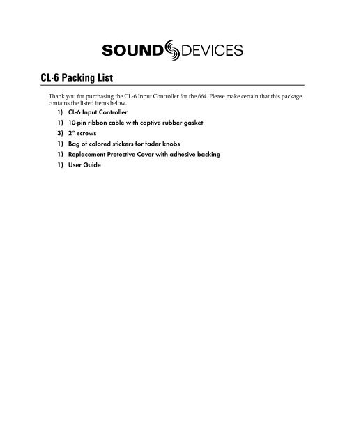
<strong>CL</strong>-6 Packing List<br />
Thank you for purchasing the <strong>CL</strong>-6 Input Controller for the 664. Please make certain that this package<br />
contains the listed items below.<br />
1) <strong>CL</strong>-6 Input Controller<br />
1) 10-pin ribbon cable with captive rubber gasket<br />
3) 2” screws<br />
1) Bag of colored stickers for fader knobs<br />
1) Replacement Protective Cover with adhesive backing<br />
1) <strong>User</strong> <strong>Guide</strong>
<strong>CL</strong>-6 Controller<br />
<strong>User</strong> <strong>Guide</strong> <strong>and</strong> <strong>Technical</strong> <strong>Information</strong><br />
<strong>Sound</strong> <strong>Devices</strong>, <strong>LLC</strong><br />
E7556 State Road 23 <strong>and</strong> 33 • Reedsburg, WI • USA<br />
+1 (608) 524-0625 • fax: +1 (608) 524-0655<br />
Toll-Free: (800) 505-0625<br />
www.sounddevices.com<br />
support@sounddevices.com
<strong>CL</strong>-6 <strong>User</strong> <strong>Guide</strong> <strong>and</strong> <strong>Technical</strong> <strong>Information</strong><br />
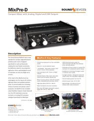
The <strong>CL</strong>-6 Input Controller connects to the top or bottom of the 664 (see Mounting the <strong>CL</strong>-6) <strong>and</strong> includes<br />
6 full-sized fader controls, PFL control, <strong>and</strong> highpass control, <strong>and</strong> dedicated L <strong>and</strong> R routing<br />
buttons for Inputs 7-12. The large, backlit Record <strong>and</strong> Stop buttons provide convenient access to transport<br />
functions. Other features include large, daylight-viewable LED meters (with track arm indicators)<br />
for tracks L, R, X1, <strong>and</strong> X2.<br />
This <strong>User</strong> <strong>Guide</strong> is a supplement to the 664 <strong>User</strong> <strong>Guide</strong>. For full details please refer to the latest 664 <strong>User</strong><br />
<strong>Guide</strong> available online at http://www.sounddevices.com/download/guides/664_en.pdf<br />
Mounting the <strong>CL</strong>-6<br />
The <strong>CL</strong>-6 Input Controller can be mounted to the top or bottom of the 664. The following installation<br />
instructions are the same whether mounting on the top or bottom. Begin by choosing which side the<br />
<strong>CL</strong>-6 will be mounted to <strong>and</strong> all directions will apply to that side of the 664.<br />
1. Power down the 664.<br />
2. Remove the disposable protective cover from the 664’s Header using a small, flat tool (A jeweler’s<br />
screwdriver works well). The protective cover is attached with adhesive.<br />
3. Similarly, remove the disposable protective cover from the <strong>CL</strong>-6 Header on the side that will<br />
connect to the 664.<br />
4. Using a Philip’s head screwdriver, remove one of the rear screws from the <strong>CL</strong>-6 (see diagram).<br />
Either screw can be removed. Remove only one rear screw. This screw will not be<br />
used with the <strong>CL</strong>-6/664 assembly.<br />
5. Using a Philip’s head screwdriver, remove the rear screw on the 664 that corresponds with<br />
the screw removed in step 3. The <strong>CL</strong>-6 can be mounted upside down. Ensure that the screw<br />
removed in this step corresponds to the desired orientation. This screw will not be used<br />
with the <strong>CL</strong>-6/664 assembly.<br />
6. Using a Philip’s head screwdriver, remove the left <strong>and</strong> right screws from the 664 (see diagram).<br />
These screws will not be used with the <strong>CL</strong>-6/664 assembly.<br />
7. Connect the ribbon cable (supplied) to the Header on the 664. Carefully slide the rubber gasket<br />
into place where the ribbon cable connects to the 664.<br />
8. With the 664 sitting on a flat, stable surface, hold the <strong>CL</strong>-6 in h<strong>and</strong> <strong>and</strong> connect the other end<br />
of the ribbon cable to the header on the <strong>CL</strong>-6.<br />
9. Insert the excess ribbon cable into the cavity behind the header on the <strong>CL</strong>-6 while lowering<br />
the <strong>CL</strong>-6 into position. Ensuring that the ribbon cable is fully within the cavity <strong>and</strong> not<br />
pinched between the <strong>CL</strong>-6 <strong>and</strong> 664, <strong>and</strong> that the rubber gasket is positioned properly.<br />
10. Using a philip’s head screwdriver, drive the 3 longer screws (supplied) through the <strong>CL</strong>-6 <strong>and</strong><br />
into the 664.<br />
1
<strong>CL</strong>-6 <strong>User</strong> <strong>Guide</strong> <strong>and</strong> <strong>Technical</strong> <strong>Information</strong><br />
Left Screw<br />
Multi-pin Header (Covered)<br />
Right Screw<br />
Rear screws<br />
Multi-pin Header (Exposed)<br />
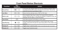
Front Panel Description<br />
4 5 6 7 8 9 10<br />
1 2 3<br />
1) Input Fader<br />
Primary control for adjusting the level of an<br />
input during operation. Ranges from off to +15<br />
dB. Nominal setting is in the middle (0 dB).<br />
2) Highpass Filter Button<br />
Push to toggle activation of Highpass Filter on<br />
the Input.<br />
3) Highpass Filter LED<br />
Illuminates blue to indicate Highpass filter is<br />
engaged on the Input.<br />
4) Track L Indicator<br />
Illuminates Blue when the Input has been<br />
routed to Track L.<br />
5) Input LED<br />
Indicates input signal activity. Illuminates in<br />
various colors <strong>and</strong> intensities to show signal<br />
level <strong>and</strong> activity. Green = signal presence (prefader),<br />
yellow = limiter activity (pre- <strong>and</strong> postfade),<br />
red = signal overload/clipping (pre- <strong>and</strong><br />
post-fade), flashing yellow = input PFL.<br />
6) Track R Indicator<br />
Illuminates Blue when the Input has been<br />
routed to Track R.<br />
11<br />
2<br />
Features <strong>and</strong> specifications are subject to change. Visit www.sounddevices.com for the latest documentation.
<strong>CL</strong>-6 <strong>User</strong> <strong>Guide</strong> <strong>and</strong> <strong>Technical</strong> <strong>Information</strong><br />
7) PFL / Input Select Switch<br />
Slide left: Pre-Fade Listen. Sends the input’s<br />
pre-fade signal to HP monitor mono mix. The<br />
664 supports simultaneous PFL of multiple<br />
inputs. Does not affect Master Output signal.<br />
Slide the switch left to activate, <strong>and</strong> again to<br />
deactivate. For momentary action, hold the<br />
switch left for one second or longer. The Input<br />
LED flashes yellow when an input’s PFL is active.<br />
Slide right: Input Settings. Enters the Input<br />
Settings Screen where basic input setup <strong>and</strong><br />
input-to-output bus routing is performed. See<br />
Input Setup <strong>and</strong> Control.<br />
8) Bus Track Arm LED’s<br />
Illuminate red to indicate the Track is armed<br />
for recording.<br />
Operation<br />
9) LED Bus Track Meters<br />
Displays levels for L, R, X1, <strong>and</strong> X2 Tracks.<br />
When the <strong>CL</strong>-6 is attached, these Track meters<br />
are removed from the LCD, which instead displays<br />
Inputs 1-12.<br />
10) Record Button<br />
Alternate, backlit Record Button. The Transport<br />
Control on the 664 operates normally when the<br />
<strong>CL</strong>-6 is attached. This button provides an additional<br />
control point for Record.<br />
11) Stop Button<br />
Alternate, backlit Stop Button. The Transport<br />
Control on the 664 operates normally when the<br />
<strong>CL</strong>-6 is attached. This button provides an additional<br />
control point for Stop.<br />
When the <strong>CL</strong>-6 is connected, the TA3 connections for Direct Inputs 1-6 on the 664 become available for<br />
balanced, line-level input. These Inputs are numbered 7-12 respectively. Routing, ISO Track arming,<br />
<strong>and</strong> Fader control all function the same as Inputs 1-6. see Input Setup <strong>and</strong> Control<br />
Bus Track meters (L, R, X1, <strong>and</strong> X2) are removed from the Main Screen to make room for the meters of<br />
Inputs 7-12:<br />
Trim Levels<br />
To adjust the trim level of Inputs 7-12, slide the Input’s Input Select Switch right to access the Input<br />
Settings Screen. From the Input Settings Screen, turn the Select Encoder to adjust trim for the Input.<br />
The trim gain will be displayed:<br />
3
<strong>CL</strong>-6 <strong>User</strong> <strong>Guide</strong> <strong>and</strong> <strong>Technical</strong> <strong>Information</strong><br />
Direct Outputs 1-6<br />
By default when the <strong>CL</strong>-6 is connected, the TA3 connections for Inputs 7-12 will function as balanced,<br />
line-level inputs. It is possible to switch each connection independently back to a direct output for its<br />
respective 1-6 Input. Slide the desired input 7-12 Input Select Switch right to access the Input Settings<br />
Screen. Press the Headphone Encoder <strong>and</strong> turn it to select the DIR OUT option.<br />
Bus Tracks (L, R, X1, <strong>and</strong> X2)<br />
To make arming <strong>and</strong> level adjustments to the bus tracks, press the Meters repeatedly from Main<br />
Screen until a Meter View is shown that displays the bus tracks (see “Meter Views” in 664 <strong>User</strong> <strong>Guide</strong>).<br />
Turn the Select Encoder to highlight the desired Bus Track. With the desired track highlighted, press<br />
the Select Encoder <strong>and</strong> turn to adjust that track’s level. To arm a track, turn the Select Encoder to highlight<br />
the track, press <strong>and</strong> hold the Meters Button, then push the Select Encoder.<br />
4<br />
Features <strong>and</strong> specifications are subject to change. Visit www.sounddevices.com for the latest documentation.
<strong>CL</strong>-6 <strong>User</strong> <strong>Guide</strong> <strong>and</strong> <strong>Technical</strong> <strong>Information</strong><br />
Quick L <strong>and</strong> R Track routing<br />
To quickly route an input to the L or R Bus track, hold down the Input’s Highpass Filter Button, then<br />
slide the Input Select Switch left for Track L or right for Track R. The Track L or Track R Indicator LED<br />
will illuminate to indicate that the Input is routed to the respective track.<br />
Highpass Filter<br />
To engage the Highpass Filter, push the Highpass Filter Button for the desired Input. The Highpass<br />
Filter LED will illuminate to indicate the filter is activated. Push the Highpass Filter button again to<br />
disable the Highpass Filter.<br />
5
<strong>CL</strong>-6 <strong>User</strong> <strong>Guide</strong> <strong>and</strong> <strong>Technical</strong> <strong>Information</strong><br />
Specifications<br />
Powering Powered by the 664.<br />
Dimensions 1.75” x 10.2” x 2.25” (H x W x D)<br />
Weight<br />
21.5 oz.<br />
Declaration of Conformity<br />
According to EN ISO/IEC 17050-1:2004<br />
Manufacturer’s Name:<br />
<strong>Sound</strong> <strong>Devices</strong>, <strong>LLC</strong><br />
Manufacturer’s Address: E7556 State Rd. 23 <strong>and</strong> 33<br />
Reedsburg, WI 53959<br />
USA<br />
Declares under sole responsibility that the product as delivered<br />
Product Name:<br />
Model Number:<br />
Product Options:<br />
<strong>CL</strong>-6 Input Controller<br />
<strong>CL</strong>-6<br />
This declaration covers all options of the above products<br />
complies with the essential requirements of the following applicable European Directives, <strong>and</strong> carries the CE marking<br />
accordingly:<br />
EMC Directive (2004/108/EC)<br />
EN 55022:2006 + A1:2007<br />
EN 55103-2:2009<br />
First date of CE approval October 17, 2012.<br />
This Declaration of Conformity applies to the above-listed products placed on the EU market after:<br />
October 17, 2012<br />
Date<br />
Matt Anderson<br />
Director of Engineering<br />
6<br />
Features <strong>and</strong> specifications are subject to change. Visit www.sounddevices.com for the latest documentation.
<strong>CL</strong>-6 <strong>User</strong> <strong>Guide</strong> <strong>and</strong> <strong>Technical</strong> <strong>Information</strong><br />
Warranty <strong>and</strong> <strong>Technical</strong> Support<br />
Warranty & Service<br />
<strong>Sound</strong> <strong>Devices</strong>, <strong>LLC</strong> warrants the <strong>CL</strong>-6 against defects in materials <strong>and</strong> workmanship for a period of<br />
TWO (2) years from date of original retail purchase.<br />
This is a non-transferable warranty that extends only to the original purchaser. <strong>Sound</strong> <strong>Devices</strong>, <strong>LLC</strong><br />
will repair or replace the product at its discretion at no charge. Warranty claims due to severe service<br />
conditions will be addressed on an individual basis.<br />
THE WARRANTY AND REMEDIES SET FORTH ABOVE ARE EX<strong>CL</strong>USIVE. SOUND DEVICES, <strong>LLC</strong><br />
DIS<strong>CL</strong>AIMS ALL OTHER WARRANTIES, EXPRESS OR IMPLIED, IN<strong>CL</strong>UDING WARRANTIES OF<br />
MERCHANTABILITY AND FITNESS FOR A PARTICULAR PURPOSE.<br />
SOUND DEVICES, <strong>LLC</strong> IS NOT RESPONSIBLE FOR SPECIAL, INCIDENTAL, OR CONSEQUEN-<br />
TIAL DAMAGES ARISING FROM ANY BREACH OF WARRANTY OR UNDER ANY OTHER LE-<br />
GAL THEORY. Because some jurisdictions do not permit the exclusion or limitations set forth above,<br />
they may not apply in all cases.<br />
For all service, including warranty repair, please contact <strong>Sound</strong> <strong>Devices</strong> for an RMA (return merch<strong>and</strong>ise<br />
authorization) before sending your unit in for repair. Product returned without an RMA number<br />
may experience delays in repair. When sending a unit for repair, please do not include accessories,<br />
including SSD drives, CF cards, batteries, power supplies, carry cases, cables, or adapters unless instructed<br />
by <strong>Sound</strong> <strong>Devices</strong>.<br />
<strong>Sound</strong> <strong>Devices</strong>, <strong>LLC</strong><br />
Service Repair RMA #XXXXX<br />
E7556 State Road 23 <strong>and</strong> 33<br />
Reedsburg, WI 53959 USA<br />
telephone: (608) 524-0625<br />
<strong>Technical</strong> Support / Bug Reports<br />
For technical support <strong>and</strong> bug reporting on all <strong>Sound</strong> <strong>Devices</strong> products contact:<br />
<strong>Sound</strong> <strong>Devices</strong>, <strong>LLC</strong><br />
E-mail: support@sounddevices.com<br />
web: www.sounddevices.com/contact_support.htm<br />
Telephone: +1 (608) 524-0625 / Toll-Free in the U.S.A.: (800) 505-0625<br />
Fax: +1 (608) 524-0655<br />
<strong>Sound</strong> <strong>Devices</strong> cannot guarantee that a given computer, software, or operating system configuration can be<br />
used satisfactorily with <strong>CL</strong>-6 generated files based exclusively on the fact that it meets our minimum system<br />
requirements. Please check with your software editing application to make certain that it is compatible with<br />
the file type selected<br />
7
<strong>CL</strong>-6 <strong>User</strong> <strong>Guide</strong> <strong>and</strong> <strong>Technical</strong> <strong>Information</strong><br />
Limitation of Liability<br />
LIMITATION ON SOUND DEVICES’ LIABILITY. SOUND DEVICES, <strong>LLC</strong> SHALL NOT BE LIABLE TO THE PURCHASER OF THIS<br />
PRODUCT OR THIRD PARTIES FOR DAMAGES, LOSSES, COSTS, OR EXPENSES INCURRED BY PURCHASER OR THIRD PAR-<br />
TIES AS A RESULT OF: ACCIDENT, MISUSE, OR ABUSE OF THIS PRODUCT OR UNAUTHORIZED MODIFICATIONS, REPAIRS,<br />
OR ALTERATIONS TO THIS PRODUCT, OR FAILURE TO STRICTLY COMPLY WITH SOUND DEVICES, <strong>LLC</strong>’S OPERATING AND<br />
INSTALLATION INSTRUCTIONS. TO THE FULLEST EXTENT PERMITTED BY LAW, SOUND DEVICES SHALL HAVE NO LIABILITY<br />
TO THE END USER OR ANY OTHER PERSON FOR COSTS, EXPENSES, DIRECT DAMAGES, INCIDENTAL DAMAGES, PUNITIVE<br />
DAMAGES, SPECIAL DAMAGES, CONSEQUENTIAL DAMAGES OR OTHER DAMAGES OF ANY KIND OR NATURE WHATSOEVER<br />
ARISING OUT OF OR RELATING TO THE PRODUCTS, THESE TERMS AND CONDITIONS OR THE PARTIES’ RELATIONSHIP,<br />
IN<strong>CL</strong>UDING, WITHOUT LIMITATION, DAMAGES RESULTING FROM OR RELATED TO THE DELETION OR OTHER LOSS OF AUDIO<br />
OR VIDEO RECORDINGS OR DATA, REDUCED OR DIMINISHED AUDIO OR VIDEO QUALITY OR OTHER SIMILAR AUDIO OR<br />
VIDEO DEFECTS ARISING FROM, RELATED TO OR OTHERWISE ATTRIBUTABLE TO THE PRODUCTS OR THE END USER’S USE<br />
OR OPERATION THEREOF, REGARDLESS OF WHETHER SUCH DAMAGES ARE <strong>CL</strong>AIMED UNDER CONTRACT, TORT OR ANY<br />
OTHER THEORY. “CONSEQUENTIAL DAMAGES”s FOR WHICH SOUND DEVICES SHALL NOT BE LIABLE SHALL IN<strong>CL</strong>UDE, WITH-<br />
OUT LIMITATION, LOST PROFITS, PENALTIES, DELAY DAMAGES, LIQUIDATED DAMAGES AND OTHER DAMAGES AND LIABILI-<br />
TIES WHICH END USER SHALL BE OBLIGATED TO PAY OR WHICH END USER OR ANY OTHER PARTY MAY INCUR RELATED TO<br />
OR ARISING OUT OF ITS CONTRACTS WITH ITS CUSTOMERS OR OTHER THIRD PARTIES. NOTWITHSTANDING AND WITHOUT<br />
LIMITING THE FOREGOING, IN NO EVENT SHALL SOUND DEVICES BE LIABLE FOR ANY AMOUNT OF DAMAGES IN EXCESS<br />
OF AMOUNTS PAID BY THE END USER FOR THE PRODUCTS AS TO WHICH ANY LIABILITY HAS BEEN DETERMINED TO EXIST.<br />
SOUND DEVICES AND END USER EXPRESSLY AGREE THAT THE PRICE FOR THE PRODUCTS WAS DETERMINED IN CONSID-<br />
ERATION OF THE LIMITATION ON LIABILITY AND DAMAGES SET FORTH HEREIN AND SUCH LIMITATION HAS BEEN SPECIFI-<br />
CALLY BARGAINED FOR AND CONSTITUTES AN AGREED ALLOCATION OF RISK WHICH SHALL SURVIVE THE DETERMINATION<br />
OF ANY COURT OF COMPETENT JURISDICTION THAT ANY REMEDY HEREIN FAILS OF ITS ESSENTIAL PURPOSE.<br />
8<br />
Features <strong>and</strong> specifications are subject to change. Visit www.sounddevices.com for the latest documentation.
<strong>CL</strong>-6 Rev. 1.02