XL-SATA User Guide and Installation Instructions - Sound Devices ...
XL-SATA User Guide and Installation Instructions - Sound Devices ...
XL-SATA User Guide and Installation Instructions - Sound Devices ...

Create successful ePaper yourself
Turn your PDF publications into a flip-book with our unique Google optimized e-Paper software.
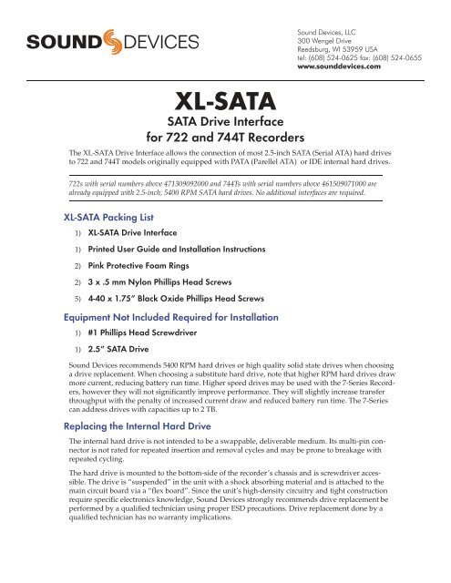
<strong>XL</strong>-<strong>SATA</strong><br />
<strong>SATA</strong> Drive Interface<br />
for 722 <strong>and</strong> 744T Recorders<br />
The <strong>XL</strong>-<strong>SATA</strong> Drive Interface allows the connection of most 2.5-inch <strong>SATA</strong> (Serial ATA) hard drives<br />
to 722 <strong>and</strong> 744T models originally equipped with PATA (Parellel ATA) or IDE internal hard drives.<br />
722s with serial numbers above 471309092000 <strong>and</strong> 744Ts with serial numbers above 461509071000 are<br />
already equipped with 2.5-inch, 5400 RPM <strong>SATA</strong> hard drives. No additional interfaces are required.<br />
<strong>XL</strong>-<strong>SATA</strong> Packing List<br />
1) <strong>XL</strong>-<strong>SATA</strong> Drive Interface<br />
1) Printed <strong>User</strong> <strong>Guide</strong> <strong>and</strong> <strong>Installation</strong> <strong>Instructions</strong><br />
2) Pink Protective Foam Rings<br />
2) 3 x .5 mm Nylon Phillips Head Screws<br />
5) 4-40 x 1.75” Black Oxide Phillips Head Screws<br />
Equipment Not Included Required for <strong>Installation</strong><br />
1) #1 Phillips Head Screwdriver<br />
1) 2.5” <strong>SATA</strong> Drive<br />
<strong>Sound</strong> <strong>Devices</strong> recommends 5400 RPM hard drives or high quality solid state drives when choosing<br />
a drive replacement. When choosing a substitute hard drive, note that higher RPM hard drives draw<br />
more current, reducing battery run time. Higher speed drives may be used with the 7-Series Recorders,<br />
however they will not significantly improve performance. They will slightly increase transfer<br />
throughput with the penalty of increased current draw <strong>and</strong> reduced battery run time. The 7-Series<br />
can address drives with capacities up to 2 TB.<br />
Replacing the Internal Hard Drive<br />
The internal hard drive is not intended to be a swappable, deliverable medium. Its multi-pin connector<br />
is not rated for repeated insertion <strong>and</strong> removal cycles <strong>and</strong> may be prone to breakage with<br />
repeated cycling.<br />
The hard drive is mounted to the bottom-side of the recorder’s chassis <strong>and</strong> is screwdriver accessible.<br />
The drive is “suspended” in the unit with a shock absorbing material <strong>and</strong> is attached to the<br />
main circuit board via a “flex board”. Since the unit’s high-density circuitry <strong>and</strong> tight construction<br />
require specific electronics knowledge, <strong>Sound</strong> <strong>Devices</strong> strongly recommends drive replacement be<br />
performed by a qualified technician using proper ESD precautions. Drive replacement done by a<br />
qualified technician has no warranty implications.
<strong>XL</strong>-<strong>SATA</strong> <strong>User</strong> <strong>Guide</strong> <strong>and</strong> <strong>Installation</strong> <strong>Instructions</strong><br />
Installing the <strong>XL</strong>-<strong>SATA</strong><br />
1. Place recorder upside down on a steady flat, non slip surface.<br />
2. With a #1 Phillips head screwdriver remove the screws in the following order. The five long black oxide screws will no<br />
longer be needed. The two smaller screws (#4 <strong>and</strong> 5) will be needed for reassembly.<br />
Attention: Remove screws in this order to avoid stripping.<br />
2<br />
3<br />
1<br />
7<br />
4<br />
6 5<br />
3. Gently remove the bottom panel. As you remove the bottom panel be careful of the internal AA battery wires as they will<br />
remain connected to the internal circuitry <strong>and</strong> the bottom panel.<br />
4. Loosen the screw of the small green circuit board holding down the hard drive ribbon cable.<br />
2
<strong>XL</strong>-<strong>SATA</strong> <strong>User</strong> <strong>Guide</strong> <strong>and</strong> <strong>Installation</strong> <strong>Instructions</strong><br />
5. Swing the small green circuit board over while pressing down on the ribbon cable to avoid snagging.<br />
6. Carefully disconnect the ribbon head mating connector from the circuit board.<br />
7. Remove the old hard drive <strong>and</strong> attached ribbon cable from the recorder.<br />
8. Place the old hard drive assembly, <strong>and</strong> the five 4-40 x 1.75” Black Oxide Phillips head screws off to the side as these are no<br />
longer needed. DO NOT DISCARD THE TWO SMALL BLACK OXIDE PHILLIPS HEAD SCREWS.<br />
9. Remove the <strong>XL</strong>-<strong>SATA</strong> Drive Interface from its packaging.<br />
3
<strong>XL</strong>-<strong>SATA</strong> <strong>User</strong> <strong>Guide</strong> <strong>and</strong> <strong>Installation</strong> <strong>Instructions</strong><br />
10. Connect the new <strong>SATA</strong> hard drive (not included) to the <strong>XL</strong>-<strong>SATA</strong> ribbon cable.<br />
11. With the ribbon face up, attach the two new small nylon screws (included) using a #1 Phillips head screwdriver.<br />
12. Slide the two new pink protective foam rings (included) over the new hard drive assembly to cover the mounting screw<br />
areas.<br />
13. Connect the <strong>XL</strong>-<strong>SATA</strong> ribbon header mating connector to the 7-Series circuit board connector.<br />
4
<strong>XL</strong>-<strong>SATA</strong> <strong>User</strong> <strong>Guide</strong> <strong>and</strong> <strong>Installation</strong> <strong>Instructions</strong><br />
14. While holding down the ribbon cable, slide the small green circuit board piece over the ribbon header mating connector.<br />
15. Using a #1 Phillips head screwdriver tighten the green circuit board piece securing the ribbon mating connector to the<br />
circuit board.<br />
16. Gently return the bottom panel to the all around panel.<br />
17. Make sure all the tabs on the all around panel fit correctly in the bottom panel grooves.<br />
18. Attach the bottom panel using a #1 Phillips head screwdriver, the original two small Black Oxide screws (#4 <strong>and</strong> 5), <strong>and</strong><br />
the five new Black Oxide screws (included). Install screws in the order defined in the illustration below. This may require<br />
holding the bottom panel down firmly to the all around panel making sure that the tabs fit correctly.<br />
Attention: Install screws in this order to avoid stripping.<br />
2<br />
3<br />
1<br />
7<br />
4<br />
6 5<br />
5
<strong>XL</strong>-<strong>SATA</strong> - © 2009, <strong>Sound</strong> <strong>Devices</strong>, LLC - Printed in U.S.A.