PIX Packing List - Sound Devices, LLC
PIX Packing List - Sound Devices, LLC
PIX Packing List - Sound Devices, LLC
- No tags were found...

You also want an ePaper? Increase the reach of your titles
YUMPU automatically turns print PDFs into web optimized ePapers that Google loves.
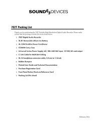
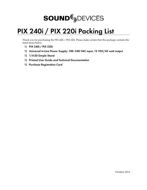
<strong>PIX</strong> 240i / <strong>PIX</strong> 220i <strong>Packing</strong> <strong>List</strong>Thank you for purchasing the <strong>PIX</strong> 240i / <strong>PIX</strong> 220i. Please make certain that this package contains thelisted items below.1) <strong>PIX</strong> 240i / <strong>PIX</strong> 220i1) Universal In-Line Power Supply; 100–240 VAC input, 12 VDC/45 watt output1) 1/4-20 Simple Stand1) Printed User Guide and Technical Documentation1) Purchase Registration CardOctober, 2014
<strong>PIX</strong> 240i / <strong>PIX</strong> 220iUser Guide and Technical InformationVersion 3.52E7556 State Rd. 23 and 33, Reedsburg, WI, USA+1 (608) 524-0625 • Toll-Free: (800) 505-0625 • fax: +1 (608) 524-0655www.sounddevices.comsupport@sounddevices.com
<strong>PIX</strong> 220i and <strong>PIX</strong> 240i Video Recorder User GuideTable of ContentsIntroductionManual Conventions ........................4Panel DescriptionsFront Panel ................................5Top and Bottom Panel .......................6Right Panel ................................7Left Panel .................................8Rear Panel ................................9<strong>PIX</strong>-CADDY II (Optional). . . . . . . . . . . . . . . . . . . . . 10PoweringRemovable Li-Ion Batteries .................11 Li-Ion Battery Charging ....................12Menu and NavigationMain View ................................13Menu ...................................14Audio ...................................14Video Inputs and OutputsFiles ....................................15LCD .....................................16Video Inputs ..............................17 Video Outputs ............................17Audio InputsAnalog Audio Inputs .......................19Digital Audio Inputs ........................19Input Linking .............................20Choosing Audio Sources .....................20Input Level Control ........................21Input Delay ...............................22Table of ContentsAudio OutputsAnalog 5-Pin XLR Output ....................23Embedded Audio on HDMI and SDI . ..........23Video Monitoring FeaturesExposure Assist ............................24Focus Assist ...............................26RecordingSelecting File Resolution and Frame Rate ......29Selecting a Video Codec ....................30Interruption of Signal During Recording .......30Headphone Output ........................23Zoom ....................................28Flip. . . . . . . . . . . . . . . . . . . . . . . . . . . . . . . . . . . . . . 28Power Loss During Recording ................31Alignment of Audio and Video ...............31Video Scaling and Frame Rate Conversion1
<strong>PIX</strong> 220i and <strong>PIX</strong> 240i Video Recorder User Guide3:2 Pulldown Removal .....................32 Up and Down Conversion ...................33PlaybackShuttle Playback ...........................35Cue Points ................................36Looping ..................................36Play <strong>List</strong> ..................................36Playback Modes ...........................37Playing Back Files on a Computer ............38Synchronization and TimecodeTimecode Reader ..........................40Internal Ambient® Lockit: Timecode Generator withSync Out .................................40<strong>PIX</strong> 220i Timecode Features .................41Timecode Modes ...........................41Timecode Frame Rate ......................42External - HDMI Timecode Mode (<strong>PIX</strong> 220i) .....42Timecode Input Sources .....................42Synchronization/Timecode Examples ..........43External ControlTriggering Recording from External Timecode ...46Triggering Recording from SDI Flag Bits .......46LANC ....................................46Switch Contact Closure ......................46USB Keyboard ............................47Table of ContentsStorage <strong>Devices</strong>Supported Storage <strong>Devices</strong> ..................48<strong>PIX</strong>-CADDY ...............................48File StorageeSATA ...................................48Formatting ...............................49 Target Storage Device for Recording ..........49File Management and MetadataFile View .................................50File Size Limit .............................51File Naming ..............................51Metadata ................................52Transfering Files to a Computer ..............53Setup and FirmwareFirmware Update ..........................54Saving and Loading Setup Files ..............54Setup Menu OptionsFile Storage ...............................57Video ....................................58Audio ....................................59Timecode/Sync ............................60Custom Default Settings and Setup Menu Option Visibility....................................54LCD Monitor ..............................61Display ..................................62System ...................................63Quick Setup ..............................64ShortcutsButton Shortcuts ...........................65 Keyboard Shortcuts ........................652v. 3.52 Features and specifications are subject to change. Visit www.sounddevices.com for the latest documentation.
<strong>PIX</strong> 220i and <strong>PIX</strong> 240i Video Recorder User GuideConnector Pin AssignmentsSpecificationsVideo ....................................67Analog Audio .............................67Digital Audio ..............................68Storage ..................................68Timecode and Sync .........................68Power ...................................68Physical ..................................68Environmental ............................68Declaration of ConformitySoftware LicenseWarranty and Technical SupportWarranty & Service ........................71Technical Support / Bug Reports ..............71Table of Contents3
<strong>PIX</strong> 220i and <strong>PIX</strong> 240i Video Recorder User GuideIntroductionThe <strong>PIX</strong> 220i and <strong>PIX</strong> 240i are highly advanced video recorders which can record digital video signalsfrom SDI or HDMI sources to an internal 2.5” drive or CompactFlash (CF) card. These recorderscan also record very high quality audio simultaneously with the video to industry-standard Quick-Time (.mov) files. QuickTime files can be edited with all major video editing programs.The <strong>PIX</strong> recorders compress the incoming video signals using the popular Apple ProRes or AvidDNxHD codecs at up to 12 bit, 4:4:4 sampling. Both codecs offer excellent video quality in a “readyto edit” file, not requiring transcoding while importing video.The <strong>PIX</strong> 240i features both SDI and HDMI inputs and outputs. The <strong>PIX</strong> 220i has HDMI input andoutput only. The <strong>PIX</strong> 240i offers a full built-in Ambient® Lockit Timecode Generator/Reader, AES/EBU audio inputs, and provisions to connect to an external, stand-alone eSATA hard drive.IntroductionManual ConventionsThis documentation addresses the <strong>PIX</strong> 220i, <strong>PIX</strong> 240i, <strong>PIX</strong> 220, and <strong>PIX</strong> 240 video recorders. Severalformatting features have been included to make navigating the guide easier.Lighter (orange) text indicates information that applies only to the <strong>PIX</strong> 240i and <strong>PIX</strong> 240.Setup Menu items are indicated with this text: Menu Category Parameter, where the menucategory is one of the items in the list displayed when the Menu button is pushed, and the parameteris an item in the list displayed when that category is selected (by pushing in on the Control Knob).Terms that refer to specific controls or functions (such as Control Knob, Menu Button, Setup Menu,etc) are capitalized. These terms are described elsewhere in this user guide (see the Panel Descriptionssection).Blue italicized text references sections of the user guide containing contextually relevant information.This guide is available as a full color PDF at http://www.sounddevices.com/download/guides/pix_en.pdf4v. 3.52 Features and specifications are subject to change. Visit www.sounddevices.com for the latest documentation.
<strong>PIX</strong> 220i and <strong>PIX</strong> 240i Video Recorder User GuidePanel DescriptionsFront Panel1112435121) LCD DisplayDisplays operating information when theOn-Screen Display (OSD) is active (seeOn-Screen Display), user interface, sourcevideo, and playback video. 5-inch display;800x480 resolution.62) Audio ButtonDisplays the Audio View. From the AudioView, all audio inputs levels can be monitoredand input levels can be controlled.3) LCD ButtonToggles the On Screen Display.4) Menu ButtonDisplays the Setup Menu.5) Files ButtonDisplays the File Browser Screen.6) Stop ButtonStops an active recording. Also stopsvideo playback.789 107) Rewind ButtonHold during Playback for 2x reverse playback(Hold for 4 seconds for 16x). Singlepress: during playback skips to previouscue or file beginning; during Pause skipsto previous frame; during Standby skipsto previous file in Take <strong>List</strong>.8) Play ButtonPlays the most recently recorded filewhen pressed. In the File <strong>List</strong> View, playsthe selected video file from the File <strong>List</strong>.Pauses video during playback.9) Fast-Forward ButtonHold during Playback for 2x forwardplayback (Hold for 4 seconds for 16x).Single press: during playback skips tonext cue or file end; during Pause skips tonext frame; during Standby skips to nextfile in Take <strong>List</strong>.Panel Descriptions5
<strong>PIX</strong> 220i and <strong>PIX</strong> 240i Video Recorder User Guide10) Record ButtonBegins recording. Optional: Splits therecording and begins writing a newfile when pressed while recording.(System Rec Button File Split)11) Power LEDHold the Menu button down, then pressthe Control Knob to power on the unit.12) Time Code / Charge LEDFlashing green: Accurate timecode is maintainedby internal Li-Ion battery.Flashing amber: battery charging. (Timecodedisplay has precedence)Alternating Amber / Green: Fault withinternal timecode battery.Solid Red (when <strong>PIX</strong> is powered up): Timecodehas been reset back to zero andneeds to be re-jammed due to <strong>PIX</strong> powerbeing off for more than 2 hours.Top and Bottom Panel56Panel Descriptions21 34 781) CompactFlash SlotInsert CompactFlash media with thelabel-side up. Visit www.sounddevices.com/approved for an up-to-date list of testedand approved cards.2) External DC Input (Hirose 4-pin)Accepts 10–18 volts DC. Hirose 4-pin connectoris wired pin-1 negative (-), pin-4positive (+).Pin-2 (-) and pin-3 (+) mustbe connected in parallel to pins 1 and 4respectively to charge attached Li-ionbatteries. The included XL-WPH3 powersupply provides positive DC on pins 3and 4 and negative DC on pins 1 and 2.3) Audio Output - 5-pin XLRTwo channels of active, balanced, lineleveloutput. Source selected in the AudioMenu.4) Audio Inputs - 3-pin XLRActive, balanced, analog microphoneor line level inputs. <strong>PIX</strong> 240i only: canbe switched to accept AES digital input,channels.6v. 3.52 Features and specifications are subject to change. Visit www.sounddevices.com for the latest documentation.
<strong>PIX</strong> 220i and <strong>PIX</strong> 240i Video Recorder User Guide5) Timecode BNCSelectable timecode input or output.Configured with Timecode/Sync Timecode BNC menu item.6) Sync Output BNCSelectable genlock or wordclock output.Configured with Setup Menu optionTimecode/Sync Sync Out.7) SDI Input BNCHD-SDI video input. Accepts 3G-SDI,HD-SDI, or SD-SDI signal with up to 8channels of embedded audio.8) SDI Output BNCHD-SDI video output. Outputs 3G-SDI,HD-SDI, or SD-SDI signal with up to 8channels of embedded audio.Right Panel1261) Time Code I/O LEMO-5Time code input and output on 5-pinLEMO® connector.2) LANC - 2.5 mm2.5 mm female connector for a standardLANC (Control-L) remote. Supportsrecord start and stop. Can also be configuredas a GPIO switch closure andused to drive an LED for record tally. SeeLANC3) HDMI OutputOutputs HDMI video with up to 8 channelsof embedded audio.4) HDMI InputAccepts HDMI (1.4a) signal with twochannels of embedded audio. The <strong>PIX</strong>does not record or display content encodedwith HDCP copy protection.5) Keyboard - USB AUSB A female connector to connect a USBkeyboard. Keyboards with integratedUSB hubs are not compatible.3 4 5 76) Control KnobThe Control Knob can be both turned andpressed. Use the Control Knob to navigatebetween menu settings and to selectmenu items. Pressing during playbackwill toggle pause / play. Turning whileplayback is paused will step forward orbackward by single frames.7) Factory Programming PortFactory use only. No user connection.Panel Descriptions7
<strong>PIX</strong> 220i and <strong>PIX</strong> 240i Video Recorder User GuideLeft Panel1 234Panel Descriptions1) eSATAp External Drive ConnectorConnection for portable, bus-powereddrives. Also compatible with (non-powered)eSATA to connect to large capacitydrives. Visit www.sounddevices.com/approvedfor an up-to-date list of tested andapproved storage devices.2) Drive BayInsert an approved 2.5-in drive mountedto a <strong>PIX</strong>-CADDY into the Drive Bay.When not in use, keep covered with thesupplied rubber grommet. Drives can behot-swapped if the drive is not being accessedfor recording or playback.3) SATA <strong>PIX</strong>-CADDY ConnectorHigh-reliability eSATAp connection designedto mate with the <strong>PIX</strong>-CADDY.4) Headphone Output - 3.5 mmTRS stereo headphone connector. Candrive headphones from 8 to 100 ohmsto very high headphone levels. Headphonevolume is controlled by holdingdown the AUDIO button and turning theControl Knob. Headphone source signalis changed by holding down the AUDIOButton and pressing the Control Knob.8v. 3.52 Features and specifications are subject to change. Visit www.sounddevices.com for the latest documentation.
<strong>PIX</strong> 220i and <strong>PIX</strong> 240i Video Recorder User GuideRear Panel3 21) Battery MountsAccepts Sony® InfoLithium L-Series batteries.Also accepts third party batteriescompatible with the Sony mount.12) FanWhisper-quiet, low-speed, single, largediameter fan. Runs continuously.3) Mounting Point - ¼ - 20Stainless-steel threaded attachment point.Panel Descriptions9
<strong>PIX</strong> 220i and <strong>PIX</strong> 240i Video Recorder User Guide<strong>PIX</strong>-CADDY II (Optional)The <strong>PIX</strong>-CADDY II is a required accessory to record video files to approved 2.5” drives. Whenremoved from a <strong>PIX</strong> 220i or <strong>PIX</strong> 240i, <strong>PIX</strong>-CADDY II operates as a high-speed drive interface to MacOS and Windows computers.53642Panel Descriptions1) FireWire 800FireWire 800 or 400 (backward compatible).Requires a powered FireWire 800 or400 port.2) eSATApHigh-speed data transfer over 5VeSATAp. Requires a 5V powered eSATApport.3) USB 3.0High-speed data transfer over USB 3.0(backward compatible with USB 2.0).4) 2.5” Drive SlotConnector for approved 2.5-inch SATAII (3.0 gb/s) drives. <strong>Sound</strong> <strong>Devices</strong> maintainsa list of tested and approved SSDdrives for use with <strong>PIX</strong> video recorders.Visit www.sounddevices.com/approved foran up-to-date list of tested and approveddrives.15) Activity LEDIlluminates when recording, playing,reading, or writing to the attached 2.5”drive. Do not remove the caddy while theActivity LED is illuminated. LED does notilluminate when connected to a computer’seSATA port.6) Release LatchesSecures the <strong>PIX</strong>-CADDY II to the recorder.Press both latches to remove the caddyassembly.10v. 3.52 Features and specifications are subject to change. Visit www.sounddevices.com for the latest documentation.
<strong>PIX</strong> 220i and <strong>PIX</strong> 240i Video Recorder User GuidePoweringThe <strong>PIX</strong> 220i and <strong>PIX</strong> 240i are powered from either removable, Li-ion rechargeable batteries orexternal DC. One or two removable 7.2 V Li-ion batteries can be mounted to the recorder and usedas either primary or backup power. The <strong>PIX</strong> automatically chooses the power source based on thevoltage level of the external power supply. If the external voltage falls below the level of attached Liionbatteries, the unit will transition to Li-ion power. The transition between external and removablebattery powering is seamless and has no affect on recording or playback operation.In the event that power is lost or media is disconnected during recording, the <strong>PIX</strong> recorder will recoverthe file upon the next power up or drive insertion. Up to 30 seconds will be lost from the end of the recording.(See “Power Loss During Recording”, page 31)Removable Li-Ion Batteries<strong>PIX</strong> recorders are compatible with Sony L-Series Li-ion rechargeable batteries. Several power capacitiesare available in this battery type, ranging from 1000 mAh to 7000 mAh. Larger amp-hour batteriesprovide more run-time.One or two L-Series batteries can be attached to the rear panel. When two batteries are attached, theyoperate in parallel. A second battery increases run time and both batteries will drain evenly. Batteriescan be hot-swapped for continuous recording.PoweringCAUTIONDanger of explosion if the battery is incorrectly replaced. Replace only with the same or equivalent type. Properly recyclebatteries. Do not crush, disassemble, incinerate, dispose in a fire or expose to high temperatures.When powered by the removable Li-ion battery, the LCD displays the battery voltage of each battery.The nominal operating voltage for Li-ion batteries is 7.2 V, with operating voltages ranging between6.8–8.5 V. When the total voltage drops to 6.9 V, the voltage display on the LCD will begin flashingred and the power LED will also flash red to warn that the battery is nearly depleted. When the voltagereaches 6.8 volts the recorder powers down—any recording in-process will automatically close(stop).CAUTIONThe XL-WPH3 power supply must be connected to a protective earthing connection in order to ensure safety. The powersupply’s cord acts as the disconnect device. The cord must be readily accessible and remain readily operable.11
<strong>PIX</strong> 220i and <strong>PIX</strong> 240i Video Recorder User GuideLi-Ion Battery ChargingWhen power is supplied to the <strong>PIX</strong> recorder on pins 1, 2 (-), and pins 3, 4 (+) of the External DCInput and the <strong>PIX</strong> recorder is powered off, the recorder will charge attached Li-ion batteries. Theincluded XL-WPH3 power supply will charge Li-ion batteries when the recorder is powered down.The optional XL-AB accessory cable can be used to power a <strong>PIX</strong> recorder from an Anton Bauer D-Tapconnector. The XL-AB will not charge attached Li-ion batteries. Make certain that the Anton Bauerbattery can supply enough power for both camera and the <strong>PIX</strong> recorder.Powering12v. 3.52 Features and specifications are subject to change. Visit www.sounddevices.com for the latest documentation.
<strong>PIX</strong> 220i and <strong>PIX</strong> 240i Video Recorder User GuideMenu and NavigationMain ViewThe Main View displays the live or playback video and the On-screen Display. the Main View is thedefault view which appears when no other views or menus are selected.On-screen DisplayThe On-screen Display (OSD) provides information superimposed over the Main View. From theMain View, the LCD button will toggle the OSD on and off. Items included in the OSD are configuredwith the Setup Menu option Display. When factory settings are loaded from the Quick Setupmenu item, all OSD items are shown.8711642141291051313Menu & NavigationOn-screen Display MenuItemDescription1. ABS Time Absolute Time: Total time of an active video recording.2. File Codec The presently selected video codec.3. File Name Name of the current file. Pressing STOP shows the next file name.4. File Resolution/Rate Resolution and frame rate of the file being recorded or played.5. Audio Input Currently selected source and channel count of audio input.6. Video Input Currently selected resolution and frame rate of the video input as well as bit depth.7. Headphone Source Current headphone routing.8. Metering Levels of audio inputs 1 and 2. Meter position and size can be adjusted from Setup Menu optionDisplay Audio Metering.9. Ext. DC Status Voltage level of external DC power.10. Battery Status Voltage level of attached L-Series batteries.11. Time/Date The current time and date.12. Timecode Current timecode value and frame rate of the recorder or playing video file.13
<strong>PIX</strong> 220i and <strong>PIX</strong> 240i Video Recorder User GuideItemDescription13. SSD/CF Status Remaining record time of each media (when video input is present) or remaining space in GB(when no video input is present), “Offline” (when no media is present), “Mounting” (when media isbecoming ready), or “No Fmt” (when media is not formatted). Asterisk indicates target recordingmedia.14. Loop / Cue Cue point and looping information is displayed here during playback.MenuPress the MENU button (keyboard: F1) to enter the Setup Menu. The Setup Menu controls settingsfor file storage, video, audio, time code/sync, system, and display. Navigate between menu itemsby turning the Control Knob and pressing it to select. When in a menu, press the MENU button togo back to the previous screen. A complete list of Setup Menu options is included in the end of thisguide. (See “Setup Menu Options”, page 57)Menu & NavigationAudioPress the AUDIO button (keyboard: F3) to enter the Audio Metering and Gain control screen. Fromthis screen, the level for both analog (XLR mic/line) and digital (XLR AES, HDMI, or SDI) audioinputs can be adjusted. Turn the Control Knob to select between audio tracks, press the ControlKnob to select a track, then turn the Control Knob to adjust the input gain for that track. (See “AudioInputs”, page 19)14v. 3.52 Features and specifications are subject to change. Visit www.sounddevices.com for the latest documentation.
<strong>PIX</strong> 220i and <strong>PIX</strong> 240i Video Recorder User GuidePress and hold the AUDIO button, and then turn the Control Knob to adjust the headphone level.Press and hold the AUDIO button, and then push the Control Knob to cycle through signal sourcefor the headphones. (See “Audio Outputs”, page 23)FilesPress the FILE button (keyboard: F2) to display the File <strong>List</strong>; A list of all of the clips (grouped by reel)on the selected storage media. Turn the Control Knob to highlight an item. Press Play to start playback of the highlighted clip.Reel groupNumber of clips in the reelindicated in brackets. PressControl Knob to expand orcollapse.ClipSingle file clip. Press ControlKnob to view details. PressPlay to play.ClipMulti-file clip. Number offiles in the clip indicated inbrackets. Press Control Knobto expand or collapse. PressPlay to play first clip.Menu & NavigationFileFile of a multi-file clip. Onlyshown when clip is expanded.Press Control Knob to viewdetails. Press Play to play.15
<strong>PIX</strong> 220i and <strong>PIX</strong> 240i Video Recorder User GuidePush the Control Knob to perform functions based on which item is highlighted:Highlighted ItemReel group. Indicated by a grey background (whennot highlighted) and a number in brackets that indicatesthe amount of clips in the reel.A Clip that consists of multiple files. Indicated bythe filename with a .mov extension and number inbrackets that indicates the amount of files that theclip consists of.A Clip that consists of one file or a File within a sublistof a multi-file clip. Indicated by the filename with.mov extensionResult of Pressing Control KnobExpands a list of clips that are within the Reel.Expands a sub-list of the files that are within the clip.Opens the File Details view where various details of the file can beviewed and the file can be deleted. (See “File Management andMetadata”, page 50)The selected drive (SSD or CF) is displayed on the top of the screen. To switch between viewing fileson CF and SSD media, scroll to the top of the list until the yellow box appears with the text “ViewCF” or “View SSD”. Push the Control Knob to access the File <strong>List</strong> for the selected media. (See “FileManagement and Metadata”, page 50)Menu & NavigationLCDFrom the Main View, the LCD button will toggle the On-ScreenDisplay (OSD) on or off. From any other view, the LCD button willreturn to the Main View.To make adjustments to the LCD backlight, button backlight, imagebrightness, image contrast, or image chroma, hold down the LCDbutton then press the Control Knob. The LCD Control Panel will appear.Turn the Control Knob to adjust the slider for the highlighted(yellow) parameter and push the Control Knob to select between theparameters.16v. 3.52 Features and specifications are subject to change. Visit www.sounddevices.com for the latest documentation.
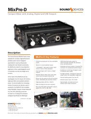
Video Inputs and OutputsVideo Inputs<strong>PIX</strong> 220i and <strong>PIX</strong> 240i Video Recorder User GuideThe <strong>PIX</strong> 240i accepts SDI or HDMI video; the <strong>PIX</strong> 220i only accepts HDMI video. Both recorders willaccept either high-definition or standard-definition rates.<strong>PIX</strong> recorders do not accept analog video signals. See the specifications section for a complete list of supportedframe rates.HDMIThe <strong>PIX</strong> 220i and <strong>PIX</strong> 240i accept HDMI version 1.4a video and audio. Supported video resolutionsand rates are listed in the specifications section. <strong>PIX</strong> recorders accept up to 10 bit, 4:4:4 video overHDMI. Two-channel digital audio embedded in the HDMI stream (32 kHz – 192 kHz) is always resampledto 48 kHz when connected to a <strong>PIX</strong> recorder.720p30/29.97, 720p25, and 720p24/23.976 are not supported on the HDMI input or the HDMI output.HDCP copy protection prevents direct digital-to-digital copying of copyrighted material. ProtectedDVDs, Blue-Rays and streaming content with HDCP encryption is not valid content and will be ignoredby the <strong>PIX</strong> recorder.SDIThe SDI input on the <strong>PIX</strong> 240i accepts video with embedded audio (up to eight channels) and embeddedSMPTE timecode. This connection accepts digital video up to 12-bit, with up to 4:4:4 colorsampling. Unlike the HDMI interface, which auto-negotiates rates between devices, what comes outof a camera’s SDI output is received by the <strong>PIX</strong> recorder with no auto-negotiation or sample rateconversion. The <strong>PIX</strong> 240i supports 3G-SDI single link, but not dual-link HD-SDI.Video Inputs & OutputsTimecode over SDI is not available when recording in standard definitionVideo OutputsThe video outputs on the <strong>PIX</strong> recorders contain incoming video when idle and while recording;during playback they contain the playback video. Both HDMI and SDI outputs are active simultaneouslyon the <strong>PIX</strong> 240i. This allows for conversion from SDI-to-HDMI and HDMI-to-SDI. Thevideo stream contains embedded audio (up to eight tracks) as defined by the Setup Menu optionAudio Audio Input. Both the SDI and HDMI outputs contain the same embedded audio.Except during playback, the resolution and frame rate of the output stream is configured in theSetup Menu option Video File Resolution/Rate. During playback, the resolution and frame rate ofthe output stream is determined by the playing video file.The HDMI outputs of the <strong>PIX</strong> recorder use the HDMI 1.3a protocol. HDMI output signal is always10-bit, 4:2:2.17
<strong>PIX</strong> 220i and <strong>PIX</strong> 240i Video Recorder User GuideEmbedded SMPTE timecode and record start and stop flags are included on the SDI output of the<strong>PIX</strong> 240i. SDI output signal can be either 10-bit 4:2:2 (YCbCr) or 12-bit 4:4:4 (YCbCr) as defined bySetup Menu option Video SDI Output Type.Timecode OverlayFor monitoring purposes, the timecode value and transport status of the <strong>PIX</strong> 240i can be visuallyoverlaid onto video output signal. The overlaid timecode value is displayed in the lower-left cornerof the video signal whenever video output is active. The color of the Timecode Overlay text willchange depending on the transport state of the <strong>PIX</strong> 240i: White=stop, Green=playback, Red=record.Access Setup Menu option Video Video Out TC Overlay to enable Timecode Overlay on SDI,HDMI, or both video outputs.Video Inputs & Outputs18v. 3.52 Features and specifications are subject to change. Visit www.sounddevices.com for the latest documentation.
<strong>PIX</strong> 220i and <strong>PIX</strong> 240i Video Recorder User GuideAudio InputsThe <strong>PIX</strong> recorders accept either two analog audio inputs on XLR connectors or two channels ofembedded audio on the HDMI input. The <strong>PIX</strong> 240i also accepts up to 8 channels of embedded audioon the SDI input and the analog XLR inputs can be switched to accept four channels (two streams) ofAES/EBU digital audio.Analog Audio Inputs<strong>PIX</strong> recorders have two high-performance analog audio inputs. These balanced inputs accept eithermic- or line-level signals, and include high-pass filters, limiters, 48V phantom power, linking, andM/S matrixing.Input Low-cut FiltersSetup Menu options: Audio Analog 1 Low cut and Audio Analog 2 Low cut.Low-cut filters on analog inputs reduce sensitivity to low frequency signals (such as wind noisefrom a microphone). Signals below the selected frequency are attenuated. The amount of attenuationincreases at lower frequencies according to the slope of the low-cut filter. The Setup Menu optionAudio Low cut Slope allows adjustment of the slope for both analog inputs.Input LimitersSetup Menu option: Audio Input Limiter (1,2).Analog inputs incorporate an advanced, analog/DSP-controlled hybrid limiter to prevent input overload.In normal operation and with proper gain settings, the limiters should rarely engage. Whenactivated, limiters prevent unusually high input signal levels from overloading the analog inputstage of the preamp.Limiting activity is indicated by a yellow segment on the audio meters (both in the Audio View andthe Main View). When the yellow segment is visible, limiting is occurring. The Input Limiters are activefor both mic- and line-level inputs. When inputs are linked, the limiters are linked.Input PolaritySetup Menu options: Audio Analog 1 Polarity and Audio Analog 2 Polarity.Input Polarity inversion (sometimes referred as phase reverse) can be applied to either analog input.This can be used to rectify incorrectly wired balanced cables, to prevent signal cancellation when asource is dual-miked from opposite directions, or reverse left/right with MS microphone configurations.Digital Audio InputsThe <strong>PIX</strong> 220i and <strong>PIX</strong> 240i accept digital audio from HDMI. Additionally, the <strong>PIX</strong> 240i accepts digitalaudio input over SDI and AES/EBU inputs. All audio is sampled at 48 kHz.HDMI / SDI Embedded AudioThe <strong>PIX</strong> 220i and <strong>PIX</strong> 240i accept two channels of embedded digital audio on the HDMI Video Input.The <strong>PIX</strong> 240i accepts up to 8 channels of digital audio on its SDI input.AES3The <strong>PIX</strong> 240i accepts AES3 (AES/EBU) digital signals with sampling rates from 32 kHz up to 192 kHzand bit depths up to 24-bits. Files recorded by the <strong>PIX</strong> 240i are uncompressed 24 bit, with samplingAudio Inputs19
<strong>PIX</strong> 220i and <strong>PIX</strong> 240i Video Recorder User Guiderates of 48 kHz. All digital signals connected to <strong>PIX</strong> are sampling rate converted to 48 kHz, includingsignals sent at 48 kHz.Input LinkingSetup Menu option: Audio Input LinkingInputs 1-2 can be linked together so that a gain adjustment to one channel will also affect the other(See “Input Level Control”, page 21). When inputs 1-2 are linked, the limiters are also linked. 48Vphantom power, analog low-cut, and analog polarity settings are set independently for each channel,even when inputs are linked.Linked inputs are useful when the <strong>PIX</strong> is receiving a left/right stereo signal on inputs 1 and 2. Examplesinclude stereo program from an external mixer, stereo program from a camera, and microphonesoriented in a stereo configuration.M/S MatrixingMid-side (MS) matrixing is a method for processing audio signal from a cardioid microphone and abidirectional microphone into a stereo signal. The cardioid microphone is the “mid” signal and connectsto input 1, and the bidirectional microphone is the “side” signal and connects to input 2. Thecardioid microphone is pointed at the sound source, and the bidirectional microphone is orientedsideways (positioned with its capsule as near as possible to the cardioid microphone’s capsule). thefollowing diagram shows the relative polar patterns of microphones in an M/S configuration.Audio InputsMid SignalSide SignalTo produce a stereo signal from an M/S configuration, the signal from both microphones must beprocessed. The <strong>PIX</strong> recorder can perform this processing on inputs 1 and 2 when Setup Menu optionAudio Input Linking is set to 1-2MS.Choosing Audio SourcesThe <strong>PIX</strong> recorders are capable of recording audio from the two analog audio inputs or digital sources(AES3 or video input). The Setup Menu option Audio Audio Input provides the following optionsfor audio sources:Audio SourceAnalog XLR 1: Analog Input XLR 12: Analog Input XLR 2AES (Digital) XLR 1-2ch 1: Channel 1, AES XLR A2: Channel 2, AES XLR AAES (Digital) XLR 1-4ch 1: Channel 1, AES XLR A2: Channel 2, AES XLR ATracks on Recorded Files and Video Outputs3: Channel 1, AES XLR B4: Channel 2, AES XLR B20v. 3.52 Features and specifications are subject to change. Visit www.sounddevices.com for the latest documentation.
<strong>PIX</strong> 220i and <strong>PIX</strong> 240i Video Recorder User GuideAudio SourceSDI/HDMI 2chSDI 4chSDI 6chSDI 8chTracks on Recorded Files and Video Outputs1: Channel 1, HDMI/SDI video input2: Channel 2, HDMI/SDI video input1: Channel 1, SDI video input2: Channel 2, SDI video input1: Channel 1, SDI video input2: Channel 2, SDI video input3: Channel 3, SDI video input1: Channel 1, SDI video input2: Channel 2, SDI video input3: Channel 3, SDI video input4: Channel 4, SDI video inputAnalog 2ch +SDI/HDMI 2ch 1: Analog Input XLR 12: Analog input XLR 2Analog 2ch +SDI 4ch 1: Analog Input XLR 12: Analog Input XLR 23: Channel 1, SDI video inputAnalog 2ch +SDI 6ch 1: Analog Input XLR 12: Analog Input XLR 23: Channel 1, SDI video input4: Channel 2, SDI video inputOFFNone3: Channel 3, SDI video input4: Channel 4, SDI video input4: Channel 4, SDI video input5: Channel 5, SDI video input6: Channel 6, SDI video input5: Channel 5, SDI video input6: Channel 6, SDI video input7: Channel 7, SDI video input8: Channel 8, SDI video input3: Channel 1, HDMI/SDI video input4: Channel 2, HDMI/SDI video input4: Channel 2, SDI video input5: Channel 3, SDI video input6: Channel 4, SDI video input5: Channel 3, SDI video input6: Channel 4, SDI video input7: Channel 5, SDI video input8: Channel 6, SDI video inputThe selected audio source is included in the HDMI and SDI streams on the Video Outputs of the <strong>PIX</strong>recorder. (See “Audio Outputs”, page 23)Input Level ControlInput audio gain is adjusted with the Control Knob when in the Audio Menu. The Audio Menu is accessedby pushing the AUDIO Button. The audio channel highlighted yellow is controllable. Turningthe Control Knob highlights a different audio input. To adjust the gain of an audio input:1. Highlight the audio input.Audio Inputs2. Push the Control Knob to enter gain adjustment mode (indicated by a blue highlight)21
<strong>PIX</strong> 220i and <strong>PIX</strong> 240i Video Recorder User Guide3. Turn the Control Knob to adjust the gain value up or down. This adjustment will affect gainin real-time.4. Push the Control Knob to exit the gain control field.Input DelayInputs 1 to 4 can be delayed up to 500 milliseconds. This is useful for aligning audio that enters the<strong>PIX</strong> recorder in real time with video from the output of a camera that can be delayed.Below is a table indicating the input delay setting (milliseconds) required to compensate for differentamounts of video delay. The top row (1-10) indicates the amount of video delay in frames and theleft column corresponds to the frame rate being used. The boxes in gray are beyond the input delaylimit of the <strong>PIX</strong> recorder. It is unlikely that a camera would introduce a video delay greater than 500ms.Audio Inputs1 2 3 4 5 6 7 8 9 1060 17 ms 33 ms 50 ms 67 ms 83 ms 100 ms 117 ms 133 ms 150 ms 167 ms59.94 17 33 50 67 83 100 117 133 150 16750 20 40 60 80 100 120 140 160 180 20030 33 67 100 133 167 20029.97 33 67 100 133 167 20024 42 83 125 167 20823.98 42 83 125 167 208When audio inputs are delayed, this delay applies to the recorded file and to the audio outputs. Thedelay can be applied to the recorded file only (and not the audio outputs) be setting Setup Menu optionAudio Input Delay to Output to Off.22v. 3.52 Features and specifications are subject to change. Visit www.sounddevices.com for the latest documentation.
<strong>PIX</strong> 220i and <strong>PIX</strong> 240i Video Recorder User GuideAudio OutputsAnalog 5-Pin XLR OutputThe two analog outputs of the <strong>PIX</strong> recorder are active-balanced, line-level outputs (+18dBu max) ona single, 5-pin XLR connection. At factory default, the source of the analog Outputs is 1 and 2. Thiscan be adjusted in the Setup Menu: Audio Output Source - XLR. The output level of each outputcan be attenuated (down to -20 dB) in the setup menu: Audio Output XLR 1 Attenuation andAudio Output XLR 2 Attenuation.Embedded Audio on HDMI and SDIThe Setup Menu parameter Audio Audio Input determines what signal is present on the HDMIand SDI output. This allows for replacement of audio coming in from a camera with audio connectedto the recorder.Headphone OutputThe <strong>PIX</strong> recorder is capable of driving headphones to extremely high sound pressure levels. Hearingexperts advise against exposure to high sound pressure levels for extended periods.The <strong>PIX</strong> recorder’s headphone output is a flexible tool for monitoring audio in the field. The headphonelevel can be adjusted while in the Main View by pressing and holding the Audio button whileturning the Control Knob.To quickly select amongst headphone sources, Press and hold the Audio button an press the ControlKnob to step through headphone source options. The Headphone Source can also be selected in theSetup Menu option Audio Headphone Source.LCD A/V AlignmentAudio signal is routed to the headphones in real-time. The video displayed on the LCD is delayedslightly. When the Setup Menu option Audio Headphone: LCD A/V Align is set to On, the audiosignal to the headphones will be delayed slightly to align with the video displayed on the LCD.Audio Outputs23
<strong>PIX</strong> 220i and <strong>PIX</strong> 240i Video Recorder User GuideVideo Monitoring FeaturesThe <strong>PIX</strong> recorders include various monitoring features to assist the camera operator during shooting.These functions only affect signal on the LCD display and will never affect the recorded video or thevideo signal sent to the <strong>PIX</strong> recorder’s outputs.Exposure AssistLCD +FILESVideo Monitoring FeaturesExposure assist features mark areas of the video image based on the exposure level. With over- orunder-exposed areas of the image clearly marked, adjustments can be made on the camera to ensurethat the signal reaching the recorder has a proper exposure. Exposure Assist is enabled by holdingdown the LCD button and pressing the FILES button. When Exposure Assist is enabled, “EXP” isdisplayed on the OSD in yellow text.When exposure assist is enabled, False Color or Zebra stripes will be overlaid on the LCD monitorsignal. The Setup Menu option LCD Monitor Exposure Assist determines which mode will activatewhen exposure assist is toggled on.The following image is a luminance ramp signal displayed on a <strong>PIX</strong> recorder with no exposure assistenabled. Screen shots in the following sections show the effect of the various Exposure Assist featureson this test signal.False ColorFalse Color exposure assist mode replaces pixels with a specific color relative to the luminance level.The two types of False Color (selectable from Setup Menu option LCD Monitor Exposure Assist)are 12-step and 4-step.24v. 3.52 Features and specifications are subject to change. Visit www.sounddevices.com for the latest documentation.
<strong>PIX</strong> 220i and <strong>PIX</strong> 240i Video Recorder User Guide12-step False Color mode divides the monitor signal into 12luminance ranges and assigns a color to each.4-step False Color mode divides the monitor signal into 4ranges and assigns a color to all but one range (this range isdisplayed without chroma). The table below illustrates thecolors as they relate to luminance levels (IRE).12-step100-108 Red95-99 Orange85-94 Yellow79-84 Light Yellow59-78 Light Grey53-58 Pink49-52 Medium Grey43-48 Green23-42 Dark Grey13-22 Light Blue3-12 Blue0-2 White4-step101+ Red99-100 Orange3-98 N/A0-2 BlueVideo Monitoring FeaturesZebrasZebra stripe exposure assist mode overlays diagonal stripes over areas that are in a defined luminancerange (Zebra 1) or above a defined luminance threshold (Zebra 2). The range for Zebra 1 is 5%above and below the IRE value of Setup Menu option LCD Monitor Zebra 1 Level. The range forZebra 2 is everything above the IRE value of Setup Menu option LCD Monitor Zebra 2 Threshold.The options for Zebra display (selectable from Setup Menu option LCD Monitor Exposure Assist)are Zebra 1, Zebra 2, or both Zebra 1 and Zebra 2 simultaneously.25
<strong>PIX</strong> 220i and <strong>PIX</strong> 240i Video Recorder User GuideZebra 270 IRE (+/- 5%)Zebra 185 IREVideo Monitoring FeaturesFocus AssistLCD +MENUFocus Assist features mark sharp edges in the video image to assist in focusing on the desired subject.Focus assist is enabled by holding down the LCD button and pressing the MENU button. Theword “FOCUS” is displayed in yellow text on the OSD when Focus Assist is enabled. There are twoavailable Focus Assist modes: Peaking and Edge Enhance.PeakingPeaking finds sharp edges in a video (based on luminance) and replaces pixels in those areas to highlightthe edges.The Setup Menu option LCD Monitor Peaking Sensitivity sets what level of sharpness will bemarked by the Peaking filter. A setting of High will mark only the sharpest areas of the image, whilea setting of Low will also mark areas that are not as sharp.The Setup Menu option LCD Monitor Peaking Background Contrast is used to adjust the area ofthe video image that is not highlighted while Peaking is enabled.The color of the Peaking marks can be set with the Setup Menu optionLCD Monitor Peaking Color.26v. 3.52 Features and specifications are subject to change. Visit www.sounddevices.com for the latest documentation.
<strong>PIX</strong> 220i and <strong>PIX</strong> 240i Video Recorder User GuideThe following image comparison demonstrates the effect of Peaking on an image with a shallowdepth-of-field and a short focal length (top) and a longer focal length (bottom).Edge EnhanceThe Edge Enhance filter uses an algorithm which enhances the variation of the luminance of alledges present in the video image. The following image comparison demonstrates the effect of EdgeEnhance on an image with a shallow depth-of-field and a short focal length (top) and a longer focallength (bottom).Video Monitoring Features27
<strong>PIX</strong> 220i and <strong>PIX</strong> 240i Video Recorder User GuideZoomLCD +AUDIOThe Zoom function enlarges the video image to a 1:1 pixel ratio. To toggle Zoom on and off, holddown the LCD button and press the AUDIO button. When Zoom is enabled, “ZOOM” is displayedon the OSD in yellow text and all other OSD elements are hidden. When zoomed, turning the ControlKnob moves vertically and REW and FF buttons move left and right respectively.FlipSome mounting situations require the <strong>PIX</strong> recorder to be upside-down or positioned in a non-standardmanner. The LCD output can be vertically or horizontally inverted with the Setup Menu optionLCD Monitor Vertical Flip Display and LCD Monitor Horizontal Flip Display.Video Monitoring Features28v. 3.52 Features and specifications are subject to change. Visit www.sounddevices.com for the latest documentation.
<strong>PIX</strong> 220i and <strong>PIX</strong> 240i Video Recorder User GuideRecordingWith a valid video signal present at the input, pushing the REC button will start recording. While recording,the REC button will illuminate red and the OSD Items Timecode, File Name, and ABS timeturn red. The <strong>PIX</strong> recorder is a record-priority device and will enter record any time the REC buttonis pressed.While recording, the FF, RW, Play, and FILES buttons are disabled. Push the Stop button to stop therecording. During both recording and playback, the MENU and FILES buttons are locked out. Whenthe Setup Menu option System REC button File Split is set to On, pushing the REC button duringrecording will begin a new file. When the recording exceeds the time set in Setup Menu optionFile Storage File Split every, a new file will be created and grouped with the other files from theclip in the File View (see File Management and Metadata).Very long clips (up to 10 hours) can be recorded when Setup Menu optionFile Storage File Split Every is set to Split Disabled. Note that this option can result in very largefiles.To discard the last take and delete the file (False take), hold down the Stop button and push theRewind button. A dialog will appear warning that the last take will be deleted and indicating the filename. Use the Control Knob to highlight OK and push the Control Knob to confirm.RecordingSelecting File Resolution and Frame RateThe <strong>PIX</strong> recorders can record video in numerous resolutions and frame rates. The Setup Menu optionVideo File Resolution/Rate sets the resolution and frame rate of recorded QuickTime files.This Setup Menu option also determines the resolution and frame rate of the live HDMI and SDIoutputs signals, except during playback. The <strong>PIX</strong> recorder can record QuickTime files in the followingresolutions and frame rates:• 1080 p 30• 1080 p 29.97• 1080 p 25• 1080 p 24• 1080 p 23.976• 1080 i 60• 1080 i 59.94• 1080 i 50• 1080 PsF 3029
<strong>PIX</strong> 220i and <strong>PIX</strong> 240i Video Recorder User Guide• 1080 PsF 29.97• 1080 PsF 25• 1080 PsF 24• 1080 PsF 23.976• 720 p 60• 720 p 59.94• 720 p 50• 720 p 30• 720 p 29.97• 720 p 25• 720 p 24• 720 p 23.976• 576 i 50 *• 480 i 59.94 *When Setup Menu option Video File Resolution/Rate is set to Same as Video Input, recordedQuickTime files and HDMI and SDI output signals will be of the same resolution and frame rate asthe input video signal.* Standard definition recording is only available for ProRes 422 HQ, ProRes 422, and ProRes 422 Proxy.Progressive Segmented Frames (PsF)Some cameras output video signal in progressive segmented frames (PsF). PsF is a method fortransmitting progressive video in an interlaced stream. A device generates PsF signal by splittingeach frame into two segments. PsF segments are the same as interlaced fields in that one segmentrepresents the even lines of a frame and the other segment represents the odd lines of a frame. PsFsegments differ from interlaced fields in that there is no motion between each segment in a pair.RecordingThe <strong>PIX</strong> will automatically sense PsF signal from most cameras that output PsF over SDI. This isaccomplished through the use a flag inserted into the SDI signal by the camera. If a camera doesnot insert this flag into the SDI stream or if it outputs PsF signal over HDMI, then the <strong>PIX</strong> settingVideo Input PsF Detect can be set to Interpret 1080i as PsF. This will force the <strong>PIX</strong> to treat all1080i signal as if it were PsF and deinterlace it accordingly.Selecting a Video CodecSetup Menu option: Video Codec.<strong>PIX</strong> has two families of intra-frame, DCT based codecs available: Apple ProRes and Avid DNxHD,with four levels of data compression available for each. Both codecs are intermediate codecs thatassist the editing process by eliminating the need to transcode video before importing into Final Cut(ProRes) or Avid (ProRes or DNxHD).ProRes is a variable data rate codec; DNxHD is a fixed data rate codec. <strong>PIX</strong> recorders support allcompression levels and bit rates of DNxHD and ProRes and automatically record the correct bit ratedependent upon the video input resolutions and frame rate. The data rates indicated in the SetupMenu item Video Codec indicate the maximum data rate at 1080p30.DNxHD 36 Mb/s only supports 1080p signal. Standard definition recording is only available for ProRes422 HQ, ProRes 422, and ProRes 422 Proxy.Interruption of Signal During RecordingIn the event that video signal is lost (an unplugged HDMI or SDI cable, for example) during recording,the <strong>PIX</strong> recorder will pause the recording and wait for video signal to be re-initialized. If videosignal is re-initialized, the <strong>PIX</strong> recorder will begin recording again to a new file of the same namewith an “A” appended to the end. Further interruptions of signal during that take will cause analphabetic filename progression (“B”, “C”, etc).30v. 3.52 Features and specifications are subject to change. Visit www.sounddevices.com for the latest documentation.
<strong>PIX</strong> 220i and <strong>PIX</strong> 240i Video Recorder User GuidePower Loss During RecordingIn the event that power is lost during recording (External and attached L-Mount batteries), the <strong>PIX</strong>recorder will attempt to recover the file when next powered on. The recovery process uses an autosavefeature during recording that operates on a 30 second interval.Alignment of Audio and VideoAn advantage to recording audio on the <strong>PIX</strong> recorders along with the video is the elimination ofaudio/video sync problems in post. The <strong>PIX</strong> recorders have many options regarding audio sourcesalong with the two options for video inputs, HDMI and SDI. Given this flexibility, care still must betaken to ensure good audio/video sync.If recording camera audio embedded on HDMI or SDI, then the audio/video alignment will be excellentprovided the alignment is proper on the camera.Most cameras have a delay of one or more frames from camera sensor to SDI/HDMI output. Bydefault, audio signal sent into the <strong>PIX</strong> recorder on AES or analog audio inputs is not delayed. Thisresults in an offset between the audio and video that must be corrected. The Setup Menu optionsAudio Input 1-4 Delay allow a delay of up to 500 milliseconds to be applied to each audio inputindependently. The amount of delay required to synchronize audio and video will depend on thespecific camera model and settings. Record a test file with sticks or a clap and measure the offset todetermine what delay to use. (See “Input Delay”, page 22)When input audio is delayed, it is delayed to the recorded video file and to the audio outputs aswell. This behavior can be modified such that the audio to <strong>PIX</strong> recorder’s line outputs is not delayed.This is particularly useful if feeding the line output audio back to the camera as a guide audio track.Change the Setup Menu option Audio Input Delays to Output to Off to disable the audio delay to theline outputs.Recording31
<strong>PIX</strong> 220i and <strong>PIX</strong> 240i Video Recorder User GuideVideo Scaling and Frame Rate Conversion<strong>PIX</strong> recorders feature powerful, hardware-based video scaling, frame rate conversion, and de-interlacing.This allows for converting the resolution and frame rate of video input to the recorded fileand to the HDMI and SDI outputs in real-time.Video scaling and/or de-interlacing is active whenever the Setup Menu optionVideo File Resolution/Rate is set to something other than Same as Video Input. Any inputsignal can be converted to any resolution. When set to record progressive frames, the <strong>PIX</strong> recorderswill convert incoming interlaced video to progressive frame video via its built-in, powerful, hardware-basedde-interlacer. The <strong>PIX</strong> recorders will also convert progressive segmented frame (PsF)video to progressive video automatically if a progressive file (for instance 1080p30) is selected inVideo File Resolution/Rate (If an interlaced file is selected, the <strong>PIX</strong> recorder will record PsF signalunaltered, but the file will be stamped as interlaced).Video Scaling & Frame Rate ConversionFrame rate conversion occurs whenever the frame rate of Video File Resolution/Rate differsfrom the frame rate of the input video signal. Frame rate conversion is achieved by appropriatelyduplicating or dropping frames. The <strong>PIX</strong> recorder will auto-sense between integer and nonintegerframe rates (for instance 30 frames vs. 29.97 frames). The <strong>PIX</strong> will not frame rate convertbetween integer and non-integer values. For example, if the incoming video signal is 1080i59.94,it can be converted to 1080p29.97 or 720p59.94 but not 1080p30 or 720p60. The Setup Menu optionVideo File Resolution/Rate contains entries with a combination of integer and non-integer framerates (such as 1080p30/29.97). When any of these options are selected, the <strong>PIX</strong> recorder will record inthe indicated integer frame rate if the input video is an integer frame or record in the indicated nonintegerframe rate if the input video is a non-integer frame rate.Not all frame rate conversions are visually desirable. When the OSD ItemFile Resolution/Rate is red, the conversion of the frame rate of the input video to the frame set byVideo File Resolution/Rate will contain a finite amount of motion judder. For example, if theincoming video is 720p60 and Video File Resolution/Rate is set to 720p50, the cadence of droppedframes may be noticeable depending on the content. Conversions which are simply 1:2 or 2:1 (suchas 1080i59.94 to 1080p29.97) introduce no motion judder. For these conversions, the OSD ItemFile Resolution/Rate stays white.When the input video signal is 720p24 or 720p23.976, up-, down-, and cross-conversion is not available.3:2 Pulldown RemovalMany cameras which shoot with a shutter speed of 24/23.976 frames per second will output signal onthe HDMI or SDI output at 60i/59.94i. To achieve this, the camera performs a “3:2 pulldown” process.The 3:2 pulldown process splits each frame into 2 fields and duplicates a field periodically. The<strong>PIX</strong> recorders are capable of removing 3:2 pulldown from a 60i/59.94i signal and converting it backto 24/23.976 progressive frames per second in real-time. The <strong>PIX</strong> 3:2 removal process actively viewsvideo fields looking for duplicates. When these duplicates are sensed, then this cadence is locked inand the appropriate extra fields are removed. The process depends on motion in the incoming video.The OSD File Resolution/Rate changes from orange to white when this cadence is detected:32v. 3.52 Features and specifications are subject to change. Visit www.sounddevices.com for the latest documentation.
<strong>PIX</strong> 220i and <strong>PIX</strong> 240i Video Recorder User GuideOrange: No 3:2 pulldown sensed in 60i/59.94i input signal. Inputvideo is being converted to 24p/23.976p using a conversionprocess which drops frames and may introduce judder.White: 3:2 pulldown sensed in 60i/59.94i input video signal.Input video signal is being converted to 24p/23.976p using 3:2pulldown removal which recreates 24p/23.976p as it is capturedfrom the camera’s shutter.Up and Down ConversionStandard-definition video resolution employs a 4:3 aspect ratio, and high-definition video resolutionemploys a 16:9 aspect ratio. Up-conversion is the process of fitting standard-definition video (with a4:3 aspect ratio) into a high-definition, 16:9 frame. Down-conversion is the opposite process.<strong>PIX</strong> recorders have various options for up and down conversion:Down-ConversionLetterbox: Maintains the same height and width ratio. Results in blank bar at top and bottom of image.Crop: Left and right side of image is cropped to fit into 4:3. Results in missing image at sides of picture.Anamorphic: Image is horizontally squashed to fit into 4:3. Results in a narrow looking image.169Letterbox43Video Scaling & Frame Rate ConversionCropAnamorphic33
<strong>PIX</strong> 220i and <strong>PIX</strong> 240i Video Recorder User GuideUp-ConversionAnamorphic: Image is horizontally stretched to fit into 16:9. Results in a wide looking image.Pillarbox: Increases size and maintains same ratio. Results in blank bar at right and left of image andpicture cropped at top and bottom.Zoom 14x9: Maintains same size but fills in remaining screen space with blank bar on the right andleft of image.Zoom Wide: Increase size and maintains ratio to full screen 16:9. Results in top and bottom beingcropped.416Video Scaling & Frame Rate Conversion3 AnamorphicPillarboxZoom 14x99Zoom Wide34v. 3.52 Features and specifications are subject to change. Visit www.sounddevices.com for the latest documentation.
<strong>PIX</strong> 220i and <strong>PIX</strong> 240i Video Recorder User GuidePlaybackThe <strong>PIX</strong> recorder can play back any QuickTime file that it records. Playback is shown on the onboardLCD display and appears at both HDMI and SDI outputs. The <strong>PIX</strong> recorder will use a connectedvideo source’s clock for its playback clock. If no video source is present, <strong>PIX</strong> will use its built-inclock. When the Play () button is pressed from the Main View, the last recorded or played file willplay. In the File View, pressing the Play () button will play the currently selected file. Push the Stop(•) button anytime to stop playback.When a file is playing, the Play () button and the OSD Items ABS Time, Timecode, and Filenamewill be green to indicate this. Press the Play () button again during playback to pause playback(The Play button will flash green). Turn the Control Knob while playback is paused to move forwardor backward in single frame increments.Fast Forward and RewindHold down the Fast Forward (>>) or Rewind () or Rewind () or Rewind() button during playback will move to the next cue point. Asingle push of the Rewind (
<strong>PIX</strong> 220i and <strong>PIX</strong> 240i Video Recorder User GuidePlaybackCue PointsDuring playback, pressing the FILES button will set a cue point. The previous cue point is alwaysdisplayed with green text in the lower left-hand corner of the OSD. To quickly jump to the next orprevious cue point, tap the Fast Forward (>>) button or Rewind () button while playback isin between the two cue points. The two points that are being loopedbetween will be displayed in green text in the bottom left-hand cornerof the OSD. To return to looping the entire clip, hold down the Play ()button and press the Rewind (
<strong>PIX</strong> 220i and <strong>PIX</strong> 240i Video Recorder User GuideFiles in a play list are indicated with a number in the Files View:By default, the <strong>PIX</strong> recorder will play files in the order that they are arranged in the File <strong>List</strong>. To playback files in a play list in the order of the play list, System Playback Mode must be set to one ofthe Play <strong>List</strong> modes.Playback ModesBy default, when a file is played, playback will stop at the end of the file. The Setup Menu optionSystem Playback Mode provides alternative playback behaviors:Play OnceThis is the default playback mode. Playback will stop when the end of the file is reached.Play Once - PauseWhen the end of the file is reached, playback will pause on the last frame of that file.Play AllWhen the end of the file is reached, the next file in the file list is played. This continues until there areno more files left in the file list to play.Play All - PauseWhen the end of the file is reached, the next file is cued on the first frame and paused.Play <strong>List</strong>When the end of a file is reached, if it is in a play list, the next file in the play list will be played.When the end of a file is reached, if it is not in a play list, playback will stop.Play <strong>List</strong> - PauseWhen the end of a file is reached, if it is in a play list, the next file in the play list will be cued on thefirst frame and paused. When the end of a file is reached, if it is not in a play list, playback will stop.Playback37
<strong>PIX</strong> 220i and <strong>PIX</strong> 240i Video Recorder User GuidePlaying Back Files on a ComputerVideo files recorded with the Apple ProRes codec require QuickTime to be installed. QuickTime canbe downloaded from http://www.apple.com/quicktime/download/. See http://software.sounddevices.com/Apple_ProRes_White_Paper_July_2009.pdf for more detailed information about the ProRes codec.Video files recorded with the Avid DNxHD codec require DNxHD drivers to be installed. Visit http://www.avid.com/dnxhd to download DNxHD drivers and for more detailed information about theDNxHD codec.Playback38v. 3.52 Features and specifications are subject to change. Visit www.sounddevices.com for the latest documentation.
<strong>PIX</strong> 220i and <strong>PIX</strong> 240i Video Recorder User GuideSynchronization and TimecodeThis section gives a concise overview of timecode and video synchronization. This information appliesprimarily to the <strong>PIX</strong> 240i and its advanced timecode and synchronization options; however it isuseful information for <strong>PIX</strong> 220i and <strong>PIX</strong> 240i users alike. For information about the <strong>PIX</strong> 220i’s timecodecapabilities. (See “<strong>PIX</strong> 220i Timecode Features”, page 41)Synchronization of video, audio, and associated timecode while recording video and audio has longbeen a problematic area. Situations where several cameras are used can complicate issues further.There may be sync issues between two (or more) cameras and/or between audio recorders because ofa) offset and b) drift. In a production environment (during recording), offset and drift are both termsto describe a timing problem between the timecode signal from two or more audio or video recorders.In a post-production environment (a non-linear editor application), offset and drift are bothterms to describe a timing problem between two or more audio or video files.Offset (matching the beginning or “head” of a take) occurs because the beginning of takes are notaligned due to the absence or misuse of timecode. Drift (matching the end or “tail” of a take) occursbecause different recorders (audio or camera) run at different rates - the beginning of files fromeach may have zero offset, but by the end they drift apart. The <strong>PIX</strong> recorders were designed withthese problems in mind and include the most comprehensive and powerful synchronization featuresavailable in a portable recorder. These features can be used to alleviate or eliminate offset and driftproblems in both production and post-production. While the <strong>PIX</strong> recorder’s design makes setting theparameters as easy as possible, a good understanding of synchronization is still necessary to properlyoperate the <strong>PIX</strong> recorder and ensure a trouble-free workflow.In a camera, the shutter, video circuitry, audio sampling, and timecode all run off of one ‘heartbeat’from its master internal clock. If this master clock is slightly fast, then the shutter, audio sampling,and timecode will be slightly fast, and if the master clock is a slightly slow, the shutter etc will be abit slightly slow also.When a <strong>PIX</strong> recorder’s video input is connected via HDMI or SDI to the camera, this heartbeat ispassed through the HDMI or SDI, and the <strong>PIX</strong> is synchronized to the camera’s internal clock as well.The <strong>PIX</strong> video and audio circuitry is clocked off of this incoming video. The <strong>PIX</strong> recorder writes filesbased on this clock as well - each audio sample and video frame written out to the file is synchronizedto the incoming video. This way, the <strong>PIX</strong> recorder is always completely in sync with the connectedcamera - there can never be any drift of audio or video between the camera and the <strong>PIX</strong>.Drift problems in a workflow can arise when more than one camera is used on a shoot, as eachcamera is driven off of its own internal master clock. Since internal master clock speed will alwaysvary from camera to camera (and vary based on temperature and time), each camera used will runat a slightly different shutter speed, audio sample rate and timecode rate. This is also true whenrecording video on a camera and recording audio on a separate recorder, as each device has its owninternal master clock. Particularly problematic are long takes where there may be significant driftfrom camera to camera from the beginning to end of the take’s file. Even if the heads match, the tailsof a take may not.These drift problems can be mitigated during recording by using a Genlock (or “Sync”) Input on acamera which takes over the camera’s internal master clock. Wiring several cameras’ Genlock Inputstogether forces all of the cameras to run at the exact same rate with no drift. This same concept appliesto audio recorders using the Word Clock input. Genlock inputs are available only on higherendcameras and Word Clock inputs are available on higher-end audio recorders.Offset problems are easier to overcome than drift problems. By feeding each recording device withthe same timecode signal, the files from different recording devices can all be in sync and there willbe no offset in post-production.Synchronization & Timecode39
<strong>PIX</strong> 220i and <strong>PIX</strong> 240i Video Recorder User GuideThe <strong>PIX</strong> 240i can address the synchronization issues of both offset and drift (heads and tails) via itsbuilt-in Ambient® Lockit with Genlock Out and Timecode Reader. The <strong>PIX</strong> 240i’s Ambient® Lockitfeatures an internal clock which has an accuracy of +/-0.2ppm (½ frame per 24 hours). Numerous <strong>PIX</strong>240i recorders can be used to maintain extremely tight synchronization.Synchronization & TimecodeTimecode ReaderThe <strong>PIX</strong> 240i includes a timecode reader which can accept incoming SMPTE timecode. The <strong>PIX</strong> 240ican read timecode from embedded SDI / HDMI, linear timecode fed into the TC I/O BNC connector,or the 5-pin LEMO® connector. The timecode reader is enabled whenever the Setup Menu optionTimecode/Sync Timecode Mode is set to any mode beginning with Ext TC, which indicates that itwill read external timecode.Timecode Reader operation is useful for simple cases where the <strong>PIX</strong> 240i’s timecode follows the cameratimecode. The timecode/sync of the <strong>PIX</strong> 240i’s file will match exactly with the camera’s file withzero-drift.In situations where a consistent offset is observed between <strong>PIX</strong> 240i files and other productionrecordings, the <strong>PIX</strong> 240i can offset the timecode stamp. The Setup Menu optionTimecode/Sync File Start TC Offset allows the user to adjust the frame offset from -10 to +10 inincrements of 1. This setting does not affect timecode on the <strong>PIX</strong> 240i’s outputs.For shoots involving more than one camera or an audio recorder, using the <strong>PIX</strong> 240i’s TimecodeGenerator can be more beneficial than using the Timecode Reader to achieve good heads and tailssync between all recordings.Internal Ambient® Lockit: Timecode Generator with Sync OutThe <strong>PIX</strong> 240i includes an internal Ambient® ACL-203 Lockit which can be used as a master sync/timecode source for cameras or audio recorders. The Lockit is an ultra-high accuracy sync/timecodegenerator with < 0.2 ppm (½ frame per 24 hours) accuracy that is suitable as a master clock in alllevels of productions. With its internal, rechargeable battery, accurate timecode is maintained for upto 2 hours after the <strong>PIX</strong> 240i is powered down. After 2 hours, the timecode value is reset. The batteryis recharged automatically.Multi-camera shoots using cameras that accept genlock input can benefit from the <strong>PIX</strong> 240i’s builtin Ambient® Lockit as their master sync and timecode source. Each <strong>PIX</strong> 240i’s files will have verytightly synchronized recordings with matching heads and tails.Additionally, even multi-camera shoots utilizing lower-cost cameras (with no genlock or timecode)can benefit from the built-in Lockit. By using the Timecode Generator to stamp the beginning of eachfile, the heads of each take will match from several recorders, even if the tails drift due to using nongenlockedcameras.Setting the Sync OutThe setting of this is parameter is found in Setup Menu option Timecode/Sync Sync Out. If not usingthe Sync Out of the <strong>PIX</strong> 240i, set the Sync Out to Off. When using the Lockit to generate the Sync(genlock) for a camera, the frame rate and resolution must be set for the camera’s sync input. Consultthe camera’s documentation for information of which rates are accepted.Additionally, there are two advanced modes under Timecode/Sync Sync Out:Genlock, Follows Video In and Wordclock, Follows Video In. Genlock, Follows Video In can beused to slave another camera’s or audio recorder’s genlock input to the camera feeding the <strong>PIX</strong>. Likewise,Wordclock, Follows Video In can be used to slave an external audio recorder to the cameradriving the <strong>PIX</strong> to achieve perfect audio sync with zero drift. Drift is less likely to be an issue whenrecordings are kept short.40v. 3.52 Features and specifications are subject to change. Visit www.sounddevices.com for the latest documentation.
<strong>PIX</strong> 220i and <strong>PIX</strong> 240i Video Recorder User GuideAdvanced: Tuning the <strong>PIX</strong>’s internal LockitThe <strong>PIX</strong> 240i contains a full Ambient® Lockit generator which has an ultra-stable, temperature-compensatedinternal oscillator. This oscillator comes from the factory pre-tuned to a very tight referencecentral clock. This oscillator can be tuned by the user by utilizing Ambient’s ACC501 Clockit Controller.This can be helpful on a larger production utilizing several <strong>PIX</strong> 240is to have the least amountof error possible. The tuning is performed by connecting the Clockit Controller to the <strong>PIX</strong> 240i’sLEMO connector and following the instrutions on the Clockit Controller.<strong>PIX</strong> 220i Timecode FeaturesThe <strong>PIX</strong> 220i is able to read timecode that is embedded on the HDMI video signal. Check yourcamera’s documentation to determine if the camera is able to send timecode over its HDMI output.When the Setup Menu option Timecode/Sync Timecode Mode is set to Ext TC (HDMI), and a camerais sending valid timecode embedded in the HDMI signal, the <strong>PIX</strong> 220i will stamp recorded fileswith this timecode. This also allows for the <strong>PIX</strong> 220i to optionally begin recording when it sensesadvancing timecode. (See “Triggering Recording from External Timecode”, page 46)Timecode ModesFreerun Timecode ModeGenerator mode. Timecode runs continuously. The value can be set by “jamming value” in the SetupMenu option Timecode/Sync Jam Received TC or by manually setting a value from the SetupMenu option Timecode/Sync Set Generator TC.Freerun Auto MuteFunctions the same as Freerun mode except timecode signal is muted from the LTC output when the<strong>PIX</strong> recorder is in stopped mode. This allows rec-run functionality when Rec Run mode is not suitable(e.g. Multi-camera shoots).In Auto mute timecode modes, the overlaid timecode displayed on the video output will continue to runwhen external timecode signal is lost.Record Run Timecode ModeGenerator mode. The recorder sends running timecode while recording and stationary timecodewhile not recording. Timecode in this mode defaults to the last stationary value at power-up. Whenswitching to record run from another mode, the internal generator will stop at the last number generated.A user-defined value can be jammed into the internal generator from the Setup Menu optionTimecode/Sync Set Generator TC.24h Run (24 hour Run)Generator mode. Timecode runs continuously. When this Timecode Mode is selected or when thetime/date is altered, the timecode value is jammed to the value of the time-of-day clock (Automaticallyupon changing to this setting and boot up). The value can be set by “jamming value” in theSetup Menu section Timecode/Sync or by manually setting a value from the Setup Menu optionTimecode/Sync Set Generator TC.24h Run Auto MuteFunctions the same as 24h Run mode except timecode signal is muted from the LTC output when the<strong>PIX</strong> recorder is in stopped mode. This allows rec-run functionality when Rec Run mode is not suitable(e.g. Multi-camera shoots).Synchronization & Timecode41
<strong>PIX</strong> 220i and <strong>PIX</strong> 240i Video Recorder User GuideIn Auto mute timecode modes, the overlaid timecode displayed on the video output will continue to runwhen external timecode signal is lost.External Timecode ModeReader mode. The <strong>PIX</strong> 240i’s internal timecode generator follows an external timecode signal appearingat the time code input or timecode embedded on the SDI or HDMI input (See “SDI Input EmbeddedTimecode”, page 43). If external timecode is disconnected (or otherwise invalid), the internalgenerator continues to run to preserve continuous timecode.External Timecode Mode - LTC HaltReader mode. The <strong>PIX</strong> 240i’s internal timecode generator follows an external timecode signal appearingat the time code input or timecode embedded on the SDI or HDMI input (See “SDI Input EmbeddedTimecode”, page 43). If external timecode is disconnected (or otherwise invalid), no timecodewill be maintained on the <strong>PIX</strong> 240i (The OSD will display dashes and timecode will not be output).Synchronization & TimecodeWhen Setup Menu option System Rec Start/Stop is set to Timecode, LTC Halt Timecode Modewill cause the <strong>PIX</strong> 240i to stop recording when timecode signal is disconnected or invalid (In additionto stopping when stationary timecode is received).Timecode Frame RateIn External mode, if the incoming frame rate does not match the frame rate as set inVideo File Resolution/Rate, the timecode frame rate display will appear orange to notify the user.The <strong>PIX</strong> will still record using the File Resolution/Rate.External - HDMI Timecode Mode (<strong>PIX</strong> 220i)This information applies to the <strong>PIX</strong> 220i only. HDMI embedded timecode on the <strong>PIX</strong> 240i is treated likeall other external timecode sources. (See “External Timecode Mode”, page 42)When the Setup Menu option Timecode/Sync Timecode Mode is set to Ext TC (HDMI), and a camerais sending valid timecode embedded in the HDMI signal, the <strong>PIX</strong> 220i will stamp recorded fileswith this timecode.Timecode Input SourcesLEMO 5-pinThe LEMO 5-pin connection provides access to timecode input, timecode output, and Ambient® tuning.Several <strong>Sound</strong> <strong>Devices</strong> cable accessories split this connection to input and output connectors onBNC (XL-LB2), XLR (XL-LX), or LEMO 5-pin (XL-LL). To accept timecode at the LEMO 5-pin input,the Setup Menu option Timecode/Sync Timecode Mode must be set to Ext TC (LTC). If timecode ispresent on the Timecode BNC connection, it will take precedence over timecode on the LEMO 5-pinconnection.Timecode BNCThe Timecode BNC will provide timecode output (by default) or timecode input. When the SetupMenu option Timecode/Sync Timecode BNC is set to Timecode Input and Setup Menu optionTimecode/Sync Timecode Mode is set to Ext TC (LTC), timecode at Timecode BNC connection willtake precedence over timecode on the LEMO 5-pin input.42v. 3.52 Features and specifications are subject to change. Visit www.sounddevices.com for the latest documentation.
<strong>PIX</strong> 220i and <strong>PIX</strong> 240i Video Recorder User GuideSDI Input Embedded TimecodeThe <strong>PIX</strong> 240i can use timecode embedded in the SDI or HDMI input signal.Timecode/Sync Timecode Mode must be set to Ext TC (SDI, HDMI).HDMI Input Embedded TimecodeThe <strong>PIX</strong> recorders can use timecode embedded in the HDMI input signal.Timecode/Sync Timecode Mode must be set to Ext TC (SDI, HDMI) on the <strong>PIX</strong> 240i orExt TC (HDMI) on the <strong>PIX</strong> 220i.Synchronization/Timecode ExamplesThe following examples illustrate common scenarios where synchronization can be employed withthe <strong>PIX</strong> 240i and other devices.Single Video Camera, no GenlockCameraIn this scenario, the video camera Video is the Output master source of the Video video Input sync. The timecode can either beread from theCameracamera or be generated by the <strong>PIX</strong> 240i. The accuracy of the recording<strong>PIX</strong> 240is dependent onthe internal clock accuracy of the camera.Genlock InputGenlock OutputTo receive timecode from the camera, set Timecode/Sync Timecode Mode to Ext TC (LTC) for camerasthat output standard SMPTE timecode to the <strong>PIX</strong> 240i’s Timecode BNC or LEMO 5-pin input.Alternatively, the <strong>PIX</strong> 240i can Video receive Output timecode from the Video SDI or Input HDMI input (if the camera sendstimecode in this Camera way) by Asetting Timecode/Sync Timecode Mode to Ext <strong>PIX</strong> TC (SDI, 240 HDMI). AGenlock InputGenlock OutputThe Setup Menu option Timecode/Sync Sync Out can be set to several valid settings, including thefollowing:• Off - sync signal is disabled.• Genlock, Follows Video Video In - Genlock Output for another camera Video is Input derived from the video signal of thesingle camera. Camera B<strong>PIX</strong> 240 B• Wordclock, Follows Video Genlock Video In Input - Output Wordclock for an audio Video Genlock device Input Output is derived from the video signalof the single Camera camera.<strong>PIX</strong> 240Single Camera with Genlock Input, Genlocked from <strong>PIX</strong>Video OutputVideo InputCamera ACameraVideo OutputVideo OutputVideo InputVideo Input<strong>PIX</strong> 240<strong>PIX</strong> 240 A<strong>PIX</strong> 240Genlock InputGenlock OutputVideo OutputVideo InputCamera B<strong>PIX</strong> 240 BIn this scenario, the <strong>PIX</strong> 240i is Video the master Outputsource of video Video sync. Input Set the output of the sync generatorto a selected rate Camera and connect A the <strong>PIX</strong> 240i Sync Out (Genlock) to the same <strong>PIX</strong> camera. 240 Feed A the timecodeoutput of the <strong>PIX</strong> 240i Genlock into the Input timecode input of the Genlock camera. OutputSynchronization & TimecodeCamera ACamera BVideo OutputVideo OutputGenlock InputVideo InputVideo InputGenlock OutputGenlock Output<strong>PIX</strong> 240 A<strong>PIX</strong> 240 B43
<strong>PIX</strong> 220i and <strong>PIX</strong> 240i Video Recorder User GuideVideo OutputCameraVideo Input<strong>PIX</strong> 240Multiple Cameras with Genlock Input, all Genlocked Genlock from Output a Single <strong>PIX</strong>CameraAVideo OutputGenlock InputVideo InputGenlock Output<strong>PIX</strong> <strong>PIX</strong> 240 240ACameraBVideo OutputGenlock InputVideo InputGenlock Output<strong>PIX</strong> <strong>PIX</strong> 240 240BSynchronization & TimecodeIn this scenario, a <strong>PIX</strong> 240i is the Video master Outputsync source for multiple Video Inputcameras , each with or without theirown <strong>PIX</strong> acting Camera as a recorder. ABecause of this locked connection, the cameras <strong>PIX</strong> can 240 be Arun indefinitelyand be assured of frame-accurate Genlock sync Input with no possibility Genlock of drift. OutputSet the output of the sync generator to a selected rate and connect the <strong>PIX</strong> 240i Sync Out (Genlock)and timecode output to multiple cameras (“mult” the genlock output). This connection uses the <strong>PIX</strong>240i as both the video sync source Video and timecode source. Heads OutputVideo Input and tails sync for the camera’s and<strong>PIX</strong> files will be perfect.Camera B<strong>PIX</strong> 240 BCamera #1 to <strong>PIX</strong> #1, Camera Genlock #2 Input to <strong>PIX</strong> #2, No Genlock OutputCamera ACamera Video OutputVideo OutputVideo OutputAudio Camera Recorder BWordclock InputVideo InputVideo InputGenlock OutputVideo Input<strong>PIX</strong> 240 A<strong>PIX</strong> 240 <strong>PIX</strong> 240 BIn this scenario, each camera is its own master video sync source , but the <strong>PIX</strong> is the source of theVideo OutputVideo Inputtimecode. The <strong>PIX</strong> 240i records its files based on the camera’s clock. The heads will match perfectly,but the tails may Camera drift depending A on the cameras’ clocks.<strong>PIX</strong> 240 AGenlock OutputAudio RecorderWordclock Input44v. 3.52 Features and specifications are subject to change. Visit www.sounddevices.com for the latest documentation.
Camera BVideo OutputCamera to <strong>PIX</strong> with Word Clock Connection to Audio Recorder<strong>PIX</strong> 220iVideoandInput<strong>PIX</strong> 240i Video Recorder User Guide<strong>PIX</strong> 240 BCamera AVideo OutputVideo InputGenlock Output<strong>PIX</strong> 240 AAudio RecorderWordclock InputThe word clock output on the <strong>PIX</strong> 240i is synchronous with incoming video signal. The word clockoutput can be used to sync external audio recorders to any camera. To enable word clock output, setSetup Menu item Timecode/Sync Sync Out to Wordclock, Follows Video In.Synchronization & Timecode45
<strong>PIX</strong> 220i and <strong>PIX</strong> 240i Video Recorder User GuideExternal ControlTriggering Recording from External TimecodeThe <strong>PIX</strong> 240i can be configured to record only when running timecode is present on the 5-pinLEMO, the Timecode BNC, or embedded timecode on the SDI or HDMI input. The <strong>PIX</strong> 220i can beconfigured to record only when running timecode is present on the HDMI input. The device that issending timecode to the <strong>PIX</strong> recorder should be configured to send running timecode when recordingand stationary timecode when not recording (often referred to as “Rec Run”). To make the <strong>PIX</strong>recorder record automatically when running timecode is sensed on the timecode input:1. Set Setup Menu option System Rec Start/Stop to Timecode2. Make sure that the device that is sending timecode is configured to send stationary timecodewhile stopped and running timecode while recording.3. Optional: To cause the <strong>PIX</strong> 240i to stop recording both when stationary LTC timecode isreceived and when LTC timecode signal is absent, set Setup Menu option Timecode/Sync Timecode Mode to Ext TC (LTC Halt).External ControlTriggering from external timecode will not cause the <strong>PIX</strong> 240i to automatically stamp external timecodeto recorded files. The timecode stamped to files is determined by the setting Timecode/Sync Timecode ModeTriggering Recording from SDI Flag BitsStart and stop flags embedded in the SDI signal from some cameras can be used to start and stoprecording of the <strong>PIX</strong> 240i. To enable this feature, set Setup Menu option System Rec Start/Stop tothe SDI Flag option that refers to the manufacturer of the connected camera.LANCThe LANC protocol can be used to start and stop recording of the <strong>PIX</strong>. A standard LANC controllercan be plugged into the 2.5 mm LANC connector on the right panel of the <strong>PIX</strong> recorder. When SetupMenu option System Rec Start/Stop is to LANC In, the <strong>PIX</strong> recorder will follow commands fromthe LANC controller. LANC commands recognized by the <strong>PIX</strong> recorder are Start and Stop recording.To send LANC commands from a controller to both a camera and a <strong>PIX</strong> recorder (or to use morethan one <strong>PIX</strong> recorder), parallel the LANC signal with a Y-cable running to both the camera and the<strong>PIX</strong>. Set the Setup Menu option System Rec Start/Stop to LANC (parallel) for any paralleled <strong>PIX</strong>units.Switch Contact ClosureThe 2.5 mm LANC connector can alternatively be configured to function as a standard GPIOlogic connection by setting the Setup Menu option System Rec Start/Stop to Switch Closureor Switch Momentary. When in either of these modes, the 2.5 mm TRS “LANC” connection is nolonger used as a LANC input and the recorder will no longer function with a LANC controller. Thewiring of the TRS connector is:• Tip: Switch Input• Ring: +5V LED voltage output (for illuminating an LED light for record tally)• Sleeve: Ground46v. 3.52 Features and specifications are subject to change. Visit www.sounddevices.com for the latest documentation.
<strong>PIX</strong> 220i and <strong>PIX</strong> 240i Video Recorder User GuideWhen the Setup Menu option System Rec Start/Stop to Switch Closure, recording will beginwhen the Switch Input (tip) is connected to ground (sleeve) and recording will stop whenthe Switch Input (tip) is disconnected from ground (sleeve). When the Setup Menu optionSystem Rec Start/Stop to Switch Momentary, recording will begin when the Switch Input (tip)is connected to ground (sleeve) and recording will stop when the Switch Input (tip) is connected toground (sleeve) a subsequent time.To use the LED output, connect an LED between the 2.5mm ring and sleeve with a series resistor.The anode (+) of the LED should connect to the ring and the cathode (-) to the sleeve. A good startingpoint for the resistor value is 220i ohms, but the value depends on the particular LED used. The ringis internally connected to 5V when recording (and to 0V otherwise) with a series 100 ohm resistor.USB KeyboardThe <strong>PIX</strong> recorders support standard USB keyboards connected to the USB A connector on the RightPanel. The keyboard can be used to navigate menus, enter text, and perform various other functions.A full list of keyboard commands is included in the rear of this guide. (See “Keyboard Shortcuts”, page65)Keyboards with integrated USB hubs are not supported.External Control47
<strong>PIX</strong> 220i and <strong>PIX</strong> 240i Video Recorder User GuideStorage <strong>Devices</strong>Supported Storage <strong>Devices</strong><strong>Sound</strong> <strong>Devices</strong> maintains a list of storage devices that are approved for use with the <strong>PIX</strong> recorders.An up-to-date list of supported storage devices can be found online: http://www.sounddevices.com/approvedApproved mechanical drives are recommended for use only in stationary applications. Excessive vibrationor motion may cause data corruption when using mechanical drives.Storage <strong>Devices</strong><strong>PIX</strong>-CADDYThe <strong>PIX</strong>-CADDY allows for simple, quick, and solid connection and removal of drives for file storageand exchange. When connected to a <strong>PIX</strong> recorder, whether powered on or off, the caddy’s USB3.0, FireWire 800 connections are disabled. When the <strong>PIX</strong>-CADDY is removed from a <strong>PIX</strong> recorder, itoperates as a high-speed data interface for transferring files from the drive to a computer. Only onedata connection can be used at a time. See <strong>PIX</strong>-CADDY documentation for details on attaching a 2.5”drive to the <strong>PIX</strong>-CADDY.eSATAAn external storage device can be used instead of the <strong>PIX</strong>-CADDY. When the <strong>PIX</strong>-CADDY is removed,the eSATAp is exposed. An external storage device with an eSATAp connector can beattached to the <strong>PIX</strong> recorder’s eSATAp Connector with a standard eSATAp cable. The drive in theenclosure must be an approved drive.This port can be used to power an external drive via 5V eSATAp, or it can be used with poweredexternal enclosures using an eSATA (non-powered) cable.48v. 3.52 Features and specifications are subject to change. Visit www.sounddevices.com for the latest documentation.
<strong>PIX</strong> 220i and <strong>PIX</strong> 240i Video Recorder User GuideFile Storage<strong>PIX</strong> recorders format and write to an exFAT filesystem. The exFAT filesystem is readable and writableby all major operating systems. 2.5” drive and CF storage devices to be used with the <strong>PIX</strong>recorder must be formatted from the <strong>PIX</strong> recorder.FormattingTo format a drive:1. Make sure the CF or 2.5” drive to be formatted is connected to the recorder.2. Open Setup Menu option File Storage Erase/Re-format.3. Choose the appropriate Erase/Re-format sub-option for the drive to be formatted (SSD orCF).4. A confirmation dialog will appear: “All data will be erased. Continue?”. Turn the controlknob to select OK.5. Use the displayed on-screen keyboard (or an external USB keyboard, if attached) to enter avolume label for the drive, and then use the Control Knob to select OK to initiate the format.Target Storage Device for RecordingThe <strong>PIX</strong> recorder can record directly to approved CF or 2.5” drives. The Setup Menu optionFile Storage Primary Drive controls which drive will be written to depending on which drivesare attached. When the primary drive is full, the <strong>PIX</strong> recorder can be configured to automaticallybegin recording to the other drive or stop recording, with the Setup Menu option File Storage When Drive is Full.Notes on automatic drive switching:• If the drive that is set as the primary drive is not attached when the Record button is pressed,the <strong>PIX</strong> will record to the alternate drive (if present).• In order for automatic switching to occur, the drive to be switched to must be attached andmounted prior to hitting Record. Drives that are not mounted prior to hitting record will not beavailable for automatic switching until recording is Stopped.File Storage49
<strong>PIX</strong> 220i and <strong>PIX</strong> 240i Video Recorder User GuideFile Management and MetadataFile ViewFiles recorded on the <strong>PIX</strong> recorder are compiled in the File View as a list of clips. Push the Filesbutton to access the File View. Clips are arranged chronologically and grouped by Reel. Turn theControl Knob to highlight individual rows in File View.When the reel number is changed (File Storage Reel) and a new clip is recorded, a new group willbe created in the file list. Rows with a grey background indicate a group of clips by Reel number.The number of clips in the reel is indicated, and the total size (in GB) of the clips within the reel isalso indicated. To browse the clips within a group, highlight the group and push the Control Knob.File Management & MetadataClips that exceed the time set in Setup Menu option File Storage File Split every will consist ofmore than one file and be grouped into one row in the File View. Clips grouped in this way will beindicated with a number following the clip name. This number represents the amount of files in theclip. Pushing the Control Knob when a multi-file clip is highlighted will open a sub-list of the filesthat make up the clip.When Setup Menu option File Storage File Split Every is set to Off, file splitting is disabled.Reel groupNumber of clips in the reelindicated in brackets. PressControl Knob to expand orcollapse.ClipSingle file clip. Press ControlKnob to view details. PressPlay to play.ClipMulti-file clip. Number offiles in the clip indicated inbrackets. Press Control Knobto expand or collapse. PressPlay to play first file.FileFile of a multi-file clip. Onlyshown when clip is expanded.Press Control Knob to viewdetails. Press Play to play.File DetailsHighlight a file and push the Control Knob to view the File Details of that file. File detail includes:• Start time code• Timecode frames-per-second• Timecode user bits• Video resolution• Video frame rate• Video codec• Media• File size• Duration• Audio Format50v. 3.52 Features and specifications are subject to change. Visit www.sounddevices.com for the latest documentation.
<strong>PIX</strong> 220i and <strong>PIX</strong> 240i Video Recorder User GuideDeleting a FileTo delete a file:1. Push the files button to enter the File View.2. Scroll with the Control Knob to highlight and select the file to be deleted.3. Highlight and select the Delete option. A dialog will appear to confirm the deletion. Turn theControl Knob to highlight and select “OK”.File Size LimitTo aid in maintaining manageable file sizes, the <strong>PIX</strong> recorder will automatically begin writing a newfile after a set amount of minutes has elapsed in a recording. The beginning of this new file will beseamless to the ending of the previous file. The default time before splitting the file is 60 minutes.The Setup Menu option File Storage File Split every adjusts the amount of time before a file splitoccurs.File NamingFiles are named according to the file name format as set with Setup Menu optionFile Storage File Name Format. The options for file name format include various combinations ofCamID, Reel, Clip, Scene/Shot, and Take metadata fields.RED File FormatFile Management & MetadataWhen the Setup Menu option File Storage File Name Format is set to RED File Format, the <strong>PIX</strong>240i will generate files that follow the same naming convention used by RED cameras:Camera LetterA001_C002_0502.movReelClip NumberDate51
<strong>PIX</strong> 220i and <strong>PIX</strong> 240i Video Recorder User GuideThe <strong>PIX</strong> 240i will extract the Camera Letter, Reel, and Clip Number from the RED and apply them tothe file’s CamID, Reel number, and Clip number respectively. See MetadataArri File FormatWhen the Setup Menu option File Storage File Name Format is set to Arri File Format, the <strong>PIX</strong>240i will generate files that follow the same naming convention used by Arri Alexa cameras:Camera IndexClip IndexB001C001_120601_R1RA.movReelClip Counter Date Unique Camera IDThe <strong>PIX</strong> 240i will extract the Unique Camera ID, Reel, and Clip Counter from the Alexa and applythem to the file’s CamID, Reel number, and Clip number respectively. (See “Metadata”, page 52)Sony File FormatFile Management & MetadataWhen the Setup Menu option File Storage File Name Format is set to Sony File Format, the <strong>PIX</strong>240i will generate files that follow the same naming convention used by Sony PMWFF5 cameras:_This option only applies to incoming SDI signal when the source is the Sony PMWF55.The Sony PMWF55 has two options for file naming: the CamID and Reel, which is supported, and Title,which is not supported.When the <strong>PIX</strong> 240i File Name Format is set to Sony File Format, and the F55 camera is set to CamIDand Reel, then the <strong>PIX</strong> recorder file names will be identical to the F55’s, and they will be placed in aReel folder derived from the Sony F55’s CamID and Reel.MetadataSeveral parameters can be set within the Setup Menu File Storage to aid in the organization of files.This metadata can be used in naming the file which is to be recorded. Folders are created on the 2.5”drive or CF card based on the Reel number. The Reel number and start timecode value are recordedwithin the QuickTime’s metadata fields.CamIDThe CamID field consists of a single alpha character. It is intended to indicate which physical camerashot the content for the take.ReelThe reel can be considered a container for all assets generatedduring a recording session or day’s work. This field consistsof a numeric value between 1 and 999. It is intended toindicate what reel the recording is part of. The <strong>PIX</strong> recorderwill create a folder at the root level for each Reel. Recordedfiles are placed inside the current Reel folder. A change tothe Reel value will automatically reset the Clip value to 1.52v. 3.52 Features and specifications are subject to change. Visit www.sounddevices.com for the latest documentation.
<strong>PIX</strong> 220i and <strong>PIX</strong> 240i Video Recorder User GuideClipThe Clip field consists of a numeric value between 1 and 999. It is intended to indicate what clipnumber the recording is. This field can be set manually and will increment each time a new file isrecorded. The Clip number will reset to 1 when the Reel number is changed.Scene/ShotThe Scene/Shot field consists of a alpha-numeric value. Use this field to indicate a descriptive namefor the current scene or shot. A change to the Scene/Shot value will automatically reset the Takevalue to 1.TakeThe Take field consists of a numeric value between 1 and 999. It is intended to indicate what takenumber the clip is, relative to the scene. This field can be set manually and will increment each timea new file is recorded. The Take number will reset to 1 when the Scene name is changed.Transfering Files to a ComputerQuickTime files on <strong>PIX</strong> formatted storage volumes (2.5” drive, CF card, or any external storagedevice) can be copied to a computer by removing the storage device from the <strong>PIX</strong> recorder and connectingit to a computer. Storage devices formatted with the <strong>PIX</strong> recorder use the exFAT filesystem.(See “File Storage”, page 49)The Firewire 800 and USB 3.0 connectors on the <strong>PIX</strong>-CADDY are disabled when the <strong>PIX</strong>-CADDY isattached to the <strong>PIX</strong> recorder. When attaching the <strong>PIX</strong>-CADDY to a computer, either the Firewire 800or the USB 3.0 connection must be used; Not both.<strong>Sound</strong> <strong>Devices</strong> recommends first copying files from the 2.5” drive or CF card to the computer firstand then editing the files. It is not recommended to edit files directly off of the 2.5” drive or CF card.Do not copy files from a computer (or any other host device) to a drive that is intended to be used by the<strong>PIX</strong> recorder. If this occurs, it is advisable to format the drive with the <strong>PIX</strong> recorder before making newrecordings.File Management & Metadata53
<strong>PIX</strong> 220i and <strong>PIX</strong> 240i Video Recorder User GuideSetup and FirmwareSetup & FirmwareFirmware UpdateAt times, <strong>Sound</strong> <strong>Devices</strong> makes updates available for <strong>PIX</strong> recorders. These updates are easy to apply:1. Download the new .prg file from the <strong>Sound</strong> <strong>Devices</strong> website.2. Copy this file to the CF card or 2.5” drive, and insert into the <strong>PIX</strong> recorder.3. Ensure that the power source for the <strong>PIX</strong> recorder is reliable. Power loss during a firmwareupgrade process can produce unexpected results.4. From the System menu in the Setup Menu, select Firmware Update. The <strong>PIX</strong> recorder willsearch for the .prg file and give the option to install the first file that it finds (cancelling thisdialog will cause the <strong>PIX</strong> to search for another .prg on any attached storage devices). Whenthe correct .prg file has been located, highlight the OK button and push the Control Knob tobegin the firmware update.5. The <strong>PIX</strong> will verify that the file is not corrupted, then it will update the firmware. When donethe unit will need to be powered down and then back up.Saving and Loading Setup FilesTo save all of the settings to a setup file, select the Setup Menu optionQuick Setup Save Settings to SSD or Save Settings to CF. Use the on-screen keyboard (or attachedUSB keyboard) to enter a name for the setup file. This will save all of the current settings to anXML file on the root of the selected storage device. To load a previously saved setup file, select theSetup Menu option Quick Setup Load Settings from SSD or Load Settings from CF.Formatting a storage device will also remove any setup files that are on the drive. Setup files can be storedon a computer and copied back to a CF or 2.5” drive to be loaded on the <strong>PIX</strong> recorder.Custom Default Settings and Setup Menu Option VisibilityThe Setup Menu option Quick Setup Load Factory Settings loads a setup that is saved internallyto the <strong>PIX</strong> when it leaves the factory. It is possible to alter this “factory” setup, so that the SetupMenu option Quick Setup Load Factory Settings will load a custom default.It is also possible to hide specific Setup Menu parameters and options. This is useful for Setup Menuoptions that are not commonly used in a particular workflow, or to simplify use when lending theunit to another user.54v. 3.52 Features and specifications are subject to change. Visit www.sounddevices.com for the latest documentation.
<strong>PIX</strong> 220i and <strong>PIX</strong> 240i Video Recorder User GuideTo customize defaults and Setup Menu option visibility:1. Attach a USB keyboard to the <strong>PIX</strong> recorder’s USB keyboard jack.2. Press the MENU button to enter the Setup Menu.3. Press Ctrl + Alt + F10 on the keyboard. If this is the first time this action has been performedsince powering the <strong>PIX</strong> recorder up, a password dialog will appear. Enter the password (thedefault password is “default”).4. After the correct password has been entered, the Settings Customization Menu will appear.Select Edit Menu & Default Values.5. The Setup Menu will be shown with a colored background. There will be check boxes next toeach menu item. Navigate the menu with the Control Knob, as usual.Setup & Firmware55
<strong>PIX</strong> 220i and <strong>PIX</strong> 240i Video Recorder User Guide6. To to change the visibility of an item in the Setup Menu, push the spacebar on the keyboardwhile the item is highlighted. Checked items will be displayed in the Setup Menu and uncheckeditems will not be displayed.Setup & FirmwareCrossed out items will be hidden7. Settings changed at this point will become the default settings.8. When finished, press Esc or F1 on the keyboard. This will show the Settings CustomizationMenu again. Select any of the save options.Keep a record of the password, if it is changed. A lost password could result in undesirable limitations.The Settings Customization Menu option Reset to Factory Settings will make all Setup Menu itemsvisible and revert default settings to factory defaults.56v. 3.52 Features and specifications are subject to change. Visit www.sounddevices.com for the latest documentation.
Setup Menu Options<strong>PIX</strong> 220i and <strong>PIX</strong> 240i Video Recorder User GuideThe Setup Menu controls a wide range of parameters for the <strong>PIX</strong>. The parameters are organized intocategories, making the setup Menu easy to navigate. The following tables show the parameter name,a description, options available, and the factory default setting where applicable.Default settings can be altered. (See “Custom Default Settings and Setup Menu Option Visibility”, page54)File Storage# Parameter Name Description Options1 Primary Drive Selects which storage device to record to. »»SSD• CF2 When Drive is Full Whether or not to automatically switch to the otherstorage device if the primary drive becomes full whilerecording.3 File Split Every Choose the recording time that will elapse before anew file is created automatically. Since DNxHD codecis variable bit rate, the size of each file will vary, eventhough the running time will be the same.4 File Name Format The format for file names as they are written to thedrive.»»Stop recording• Switch to other drive• 1 min• 5 min• 10 min• 15 min• 30 min»»60 min• Split Disabled (10 Hours Max)»»Drive_Reel_Clip.mov• Reel_Clip.mov• CamID_Reel_Clip.mov• Reel_Scene_Take.mov• Scene_Take.mov• RED File Format• Arri File Format• Sony File Format5 CamID »»A(single alpha to “Z”).6 Reel • 1(numeric)7 Clip »»1(numeric)8 Scene/Shot »»“Scene 1”(multi alphanumeric)9 Take »»1(numeric)10 Erase/Reformat • Erase/Re-format: SSD• Erase/Re-format: CFSetup Menu Options57
<strong>PIX</strong> 220i and <strong>PIX</strong> 240i Video Recorder User GuideSetup Menu OptionsVideo# Parameter Name Description Options1 Video Input Physical source to derive recorded video from. • HDMI»»SDI1223344556File Resolution/RateCodecUp ConversionThe resolution and frame to convert input video to.This will affect files recorded and all video outputs.The video codec to use for encoding. Note for DNxHDthat the rates listed are assuming 1080p30. If a differentresolution and frame rate is selected, the <strong>PIX</strong>recorder will use the corresponding DNxHD data rate.»»Same as Video Input• 1080p30/29.97• 1080p25• 1080p24/23.976• 1080i60/59.94• 1080i50• 1080PsF30/29.97• 1080PsF25• 1080PsF24/23.976• 720p60/59.94• 720p50• 720p30/29.97• 720p25• 720p24/23.976• 576i59 (PAL)• 480i59.94 (NTSC)• DNxHD 220x 220Mb/s, 10bit• DNxHD 220 220Mb/s, 8bit• DNxHD 145 145Mb/s, 8bit• DNxHD 36 36Mb/s, 8bit• ProRes 4444 330Mb/s, 12-bit• ProRes 422HQ 220Mb/s, 10bit»»ProRes 422 145Mb/s, 10bit• ProRes 422LT 100Mb/s, 8bit• ProRes 422Proxy 36Mb/s, 8bit• 4:3->16:9 Anamorphic»»4:3->16:9 Pillar Box• 4:3->16:9 Zoom Letterbox• 4:3->16:9 Zoom 14:9• 4:3->16:9 Zoom WideDown Conversion »»16:9->4:3 Letterbox• 16:9->4:3 Crop• 16:9->4:3 AnamorphicInput PsF DetectWhen set to “Auto”, the <strong>PIX</strong> will sense PsF signalbased on a flag within the signal stream. Most deviceswith SDI output will provide this flag, however someSDI outputs and all HDMI outputs will not provide thisflag. When sending PsF signal from these devices,choose “Interpret 1080i as PsF”7 SDI Output Type HD output type employs SMPTE 292M / HD-SDI onSDI output. 3G output type employs SMPTE 424M /3G-SDI on SDI output.8 Video Out TC Overlay Superimpose the current timecode over the video signalon the selected output. Timecode value appears inlower left corner of the frame.»»Auto• Interpret 1080i as PsF»»HD (4:2:2 10-bit)• 3G (4:4:4 12-bit)»»Off• SDI out• HDMI out• SDI + HDMI out58v. 3.52 Features and specifications are subject to change. Visit www.sounddevices.com for the latest documentation.
<strong>PIX</strong> 220i and <strong>PIX</strong> 240i Video Recorder User GuideAudio# Parameter Name Description Options1 Audio Input Physical source to derive recorded audio from. »»Analog XLR• AES (Digital) XLR 1-2ch• AES (Digital) XLR 1-4ch• SDI/HDMI 2ch• SDI 4ch• SDI 6ch• SDI 8ch• Analog 2ch + SDI/HDMI 2ch• Analog 2ch + SDI 4ch• Analog 2ch + SDI 6ch• OFF2 Analog 1 Source Selects the input level and whether or not phantompower should be applied to analog input 1.3 Analog 2 Source Selects the input level and whether or not phantompower should be applied to analog input 2.4 Analog 1 Low cut Engages low-cut filter on analog Input 1 at the specifiedfrequency.5 Analog 2 Low cut Engages low-cut filter on analog Input 2 at the specifiedfrequency.»»Mic• Mic 48V• Line• Line 48V»»Mic• Mic 48V• Line• Line 48V»»OFF• 40Hz• 80Hz• 120Hz• 160Hz• 200Hz• 240iHz»»OFF• 40Hz• 80Hz• 120Hz• 160Hz• 200Hz• 240iHz6 Low cut Slope Selects the curve of the analog low-cut filters. • 6dB/oct»»12dB/oct7 input Limiter (1,2) Toggles input limiters on analog inputs. »»On• Off8 Analog 1 Polarity Selects normal or inverse polarity for analog Input 1. »»Normal• Reverse9 Analog 2 Polarity Selects normal or inverse polarity for analog Input 2. »»Normal• Reverse10 Input 1 Delay Applies the specified amount (in milliseconds) ofdigital delay to Input 1.11 Input 2 Delay Applies the specified amount (in milliseconds) ofdigital delay to Input 2.12 Input 3 Delay Applies the specified amount (in milliseconds) ofdigital delay to Input 3.13 Input 4 Delay Applies the specified amount (in milliseconds) ofdigital delay to Input 4.»»0ms(numeric 0-500)»»0ms(numeric 0-500)»»0ms(numeric 0-500)»»0ms(numeric 0-500)Setup Menu Options59
<strong>PIX</strong> 220i and <strong>PIX</strong> 240i Video Recorder User GuideSetup Menu Options# Parameter Name Description Options1214131514161517161817191820Input LinkingOutput Source - XLRSelects whether Input 1 and Input 2 gains are controlledindependantly (Unlinked), together (1-2), ortogether with MS decoding (1-2MS).The audio channels sent to the analog XLR outputs.Left of the comma represents left output and right ofthe comma represents right output.»»Unlinked• 1-2• 1-2MS»»1,2• 3,4• 5,6• 7,8• 1357,2468• 12345678Output XLR 1 Attenuation Attenuate analog output 1 by 1 dB increments. »»0 dB(numeric 0-20)Output XLR 2 Attenuation Attenuate analog output 2 by 1 dB increments »»0 dB(numeric 0-20)Input Delay to OutputHeadphone SourceHeadphone: LCD A/V AlignTimecode/SyncToggles whether or not Input Delay affects audiosignal to the main audio outputs.The audio channels sent to the headphone output.Left of the comma represents left headphone channeland right of the comma represents right headphonechannel.Delays audio to Headphone output to align with videoon LCD.»»On• Off»»1,2• 3,4• 5,6• 7,8• 1357,2468• 12345678»»Off• On# Parameter Name Description Options1 Timecode Mode Sets the running mode for the internal timecodegenerator and/or the method which the <strong>PIX</strong> recorderreceives SMPTE timecode. (See “TimecodeModes”, page 41)2 Drop Frame Enable Enable or disable drop frame timecode. »»Off• On»»Off• Freerun• Freerun Auto Mute• Record run• 24h Run• 24h Run Auto Mute• Ext TC (LTC)• Ext TC (LTC Halt)»»Ext TC (SDI, HDMI)• Ext TC (HDMI) <strong>PIX</strong> 220i only60v. 3.52 Features and specifications are subject to change. Visit www.sounddevices.com for the latest documentation.
<strong>PIX</strong> 220i and <strong>PIX</strong> 240i Video Recorder User Guide# Parameter Name Description Options3 Sync Out Determines whether the signal on the Sync OutputBNC is genlock or wordclock, and determines thesync reference for that signal. When settings of aresolution / frame rate are selected, the Sync OutBNC will supply genlock signal at the specified ratethat reference the internal Ambient® Lockit.4 Timecode BNC Selects whether the Timecode BNC functions as aninput or output for SMPTE timecode.25Auto-Record Hold Off »»0 sec(numeric 0-8)6 Jam Received TC Opens a dialog that displays incoming timecodevalue in realtime (RxTC), incoming userbits (UB),transmitting/internal (Ambient® Lockit) timecode value(GENTC), and transmitting/internal userbits (UB).7 Jam time Of Day Sets the internal timecode clock to the current timeof day.8 Set Generator TC Sets the Ambient® Lockit timecode generator value inHH:MM:SS.FF format.9 Set Generator UBits Sets userbits of the Ambient® Lockit timecodegenerator.310File Start TC OffsetSets the amount of offset (in frames) to apply to thetimecode value that is stamped to recorded files. Thissetting does not affect timecode output of the <strong>PIX</strong>240i.»»Off• 1080p30• 1080p29.97• 1080p25• 1080p24• 1080p23.976• 1080i60/PsF30• 1080i59.94/PsF29.97• 1080i50/PsF25• 1080PsF24• 1080PsF23.976• 720p60• 720p59.94 (29.97)• 720p50• 720p30• 720p29.97• 720p25• 720p24• 720p23.976• 576i50 (PAL)• 480i59.94 (29.97 NTSC)• Genlock, Follows Video In• Wordclock, Follows Video In• Timcode Output»»Timecode Input• Push Control Knob to jam internaltimecode to incoming (RxTC)timecode.• Push Menu button to back out.»»00:00:00.00(Timecode value)»»00 00 00 00(Hex: 00-FF for each slot)»»0(numeric -10 to +10)Setup Menu OptionsLCD Monitor# Parameter Name Description Options1 Exposure Assist »»False Color, 12-step• False Color, 4-step• Zebras 1• Zebras 2• Zebras 1+22 Focus Assist »»Peaking• Edge Enhance61
<strong>PIX</strong> 220i and <strong>PIX</strong> 240i Video Recorder User GuideSetup Menu Options62# Parameter Name Description Options3 Zebra 1 Level »»70 IRE +/-5%(numeric 50-108)4 Zebra 2 Threshold »»85 IRE(numeric 70-108)5 Peaking Color • White»»Red• Blue• Green• Yellow6 Peaking Sensitivity • High»»Mid• Low7 Peaking Background Contrast8 Vertical Flip Display »»Off• On9 Horizontal Flip Display »»Off• OnDisplay»»1x• 0.5x• 0.25x• No Background# Parameter Name Description Options1 ABS Time Display of absolute record time. »»On• Off2 File Codec Display of current file codec »»On• Off3 File Name Display of current file name »»On• Off4 File Resolution/Rate Display of current file resolution »»On• Off5 Input - Audio Display of audio input levels for channels 1 and 2 »»On• Off6 Input - Video Display of video input resolution and rate »»On• Off7 Headphone Source Display of headphone audio source »»On• Off8 Audio Metering Display of audio meters for inputs 1 and 2 • Off»»Top (wide)• Top (thin)• Bottom (thin)• Left (thin)• Right (thin)9 Ext DC Status Display of voltage for external DC input »»On• Off10 Battery Status Display of voltage levels for both onboard Li-ion batteries»»On• Off11 Time/date Display of time of day and date »»On• Off12 Timecode Display of current timecode value »»On• Offv. 3.52 Features and specifications are subject to change. Visit www.sounddevices.com for the latest documentation.
<strong>PIX</strong> 220i and <strong>PIX</strong> 240i Video Recorder User Guide# Parameter Name Description Options13 SSD Status Display of time remaining (or offline) status of theSSD14 CF Status Display of time remaining (or offline) status of the CFcard»»On• Off»»On• Off15 Cue Marker Display of cue information during playback »»On• OffSystem# Parameter Name Description Options1 Test Signal Generator »»Off• On2 Audio Tone Level The level (in dBFS) of generated audio tone. »»-20dBFS(numeric -40 - 0)3 HP Warning Bell Level Adjusts the level of the heaphone warning bell sound »»-20dBFS(Off to -12dBFS)4 Time Zone Selects the international timezone »»(GMT-06:00) Central Time (US)(All GMT zones)5 Daylight Saving Toggles daylight saving on or off for the time-of-dayclock6 Time Format Selects between 12 or 24 hour format for the time-ofdayclock7 Date Format Selects between MM/DD/YY and DD/MM/YY dateformat8 Set Date/Time Set the time and date9 Rec Start/Stop Determines what method the <strong>PIX</strong> recorder uses toautomatically start and stop recording.10 Rec button File Split Whether or not a new file will be created when theREC button is pushed during recording.11 Playback Mode Upon reaching the end of a file during playback, the<strong>PIX</strong> recorder will return to the Main View (Play Once)or pause on the last frame (Play Once - Pause)12 Shortcuts Displays a dialog that shows all shortcut button combinations.This is not a setting, but a helpful reference.»»Off• On»»12h• 24h»»MM/DD/YY• DD/MM/YY»»Switch Closure• Switch Momentary• LANC In• LANC (parallel)• SDI Flag - RED• SDI Flag - Panasonic• SDI Flag - Panasonic (Varicam)• SDI Flag - Canon• SDI Flag - Sony• SDI Flag - Arri• SDI Flag - <strong>PIX</strong>• Timecode• On»»Off»»Play Once• Play Once - Pause• Play All• Play All - Pause• Play All - Loop• Play <strong>List</strong>• Play <strong>List</strong> - Pause• Play <strong>List</strong> - LoopSetup Menu Options63
<strong>PIX</strong> 220i and <strong>PIX</strong> 240i Video Recorder User Guide# Parameter Name Description Options13 Info Displays a dialog indicating firmware version andserial number. This is not a setting, but a helpful reference.14 Update Software Searches attached drives for a .prg firmware file andbegins the firmware update process.Quick Setup# Parameter Name Description Options1 Load Factory Settings Loads default setup2 Load Settings From SSD Loads selected setup from setups saved on the SSD • All settings files located on SSD3 Load Settings From CF Loads selected setup from setups saved on the CF • All settings files located on CF4 Save Settings to SSD Opens dialog to name and save current setup to SSD5 Save Settings to CF Opens dialog to name and save current setup to CFSetup Menu Options64v. 3.52 Features and specifications are subject to change. Visit www.sounddevices.com for the latest documentation.
Shortcuts<strong>PIX</strong> 220i and <strong>PIX</strong> 240i Video Recorder User GuideButton ShortcutsButton CombinationFunctionAUDIO + Control Knob push Select headphone audio source.AUDIO + Control Knob rotate Adjust headphone gain.LCD + Control Knob push Adjust LCD Backlight, LCD brightness, LCD contrast, LCD chroma and button backlight.Hold LCDTurns off LCD display.MENU + FILESButton lock options: Unlock Buttons, Lock Non-Transport Buttons, or Lock All Buttons.STOP + REWFalse take.LCD + AUDIOToggle Zoom on LCD displayLCD + MENUToggle Focus Assist on LCD displayLCD + FILESToggle Exposure Assist on LCD displayPLAY + FFBegin looping between cue points when in loop playback modePLAY + REWBegin looping of clip when in loop playback modeFILESWhen in playback or record mode: Set a cue pointHold FILESWhen in playback or record mode: Delete last cue pointKeyboard ShortcutsF1F2F3F4Ctrl + RCtrl + SF1, F2, F3, and F4 keys can be pushed in combinations to activate button shortcuts.Space BarLeft ArrowRight ArrowEnterUp ArrowDown ArrowMenu ButtonCtrl + LCtrl + QButtonCtrl + Alt + F10 (in Menu only)Home (In Menu and File <strong>List</strong> only)End (In Menu and File <strong>List</strong> only)Page Up (In Menu and File <strong>List</strong> only)Page Down (In Menu and File <strong>List</strong> only)MENU ButtonFILES ButtonAUDIO WindowLCD ButtonRecord ButtonStop ButtonPlay ButtonDuring playback: Rewind ButtonIn menus: Same as Escape keyDuring playback: Fast-Forward ButtonIn menus: Same as Enter keyRotary Encoder pushRotary Encoder turn (up)Rotary Encoder turn (down)MENU ButtonLoop Mode toggleDelete Que MarkerEnters Menu CustomizationSkips to top of the listSkips to bottom of the listSkips to top of visible itemsSkips to bottom of visible itemsFunctionShortcuts65
<strong>PIX</strong> 220i and <strong>PIX</strong> 240i Video Recorder User GuideConnector Pin AssignmentsConnector Pin Assignments NotesXLR-F(Analog inputs)1–ground2–signal (+)3–signal (-)Mates with XLR-Male connector7.5k ohm input impedance, mic level20k ohm input impedance, line level, activebalancedXLR-F(AES inputs)1–ground2–signal (+)3–signal (-)Mates with XLR-Male connectorTransformer balancedAES3 specificationConnector Pin AssignmentsXLR-M 5-pin(Analog outputs)3.5mm TRS(Headphone output)BNC(Timecode output)BNC(SDI input & SDI output)BNC(Genlock or Wordclockoutput)5-pin LEMOTimecode I/O1– Ground2– Channel 1 Positive (+)3– Channel 1 Negative (-)4– Channel 2 Positive (+)5– Channel 2 Negative (-)Tip–signal LRing–signal RSleeve–signal groundCenter pin–signalSleeve–ground1–ground2–SMPTE TC In3–ASCII in/out4–tuning out5–SMPTE TC outMates with XLR-Female 5-pin connector120 ohm output impedance, active balancedMates with 3.5 mm TRS jack.Mates with BNC male connectorUnbalanced, coaxial connectionMates with BNC male connectorUnbalanced, coaxial connection, 75 ohm connectorsrecommendedMates with BNC male connectorUnbalanced, coaxial connection, 75 ohm connectorsrecommendedMates with male LEMO B-series connectorPin assignments as viewed on panel-mountedconnector2.5mm TRSLANC2.5mm TRSGPIOTip–switch closureRing-LED driverShield–groundMates with 2.5 mm male connectorMates with 2.5 mm male connectoreSATAp FemaleMates with eSATAp male connectorAccessible only when <strong>PIX</strong>-CADDY is notinsertedUSB-AKeyboard InputFor use with USB Keyboards only. Data transferis not supportedHirose 4-pinDC Input1 – ground2 – ground3 – DC (+) *4 – DC (+)10-17 Volt DC input. *Pin 3 operates batterycharger for Li-Ion batteries. Mates with <strong>Sound</strong><strong>Devices</strong> XL-NPH and XL-WPH3 powering accessories.See Accessories for details.66v. 3.52 Features and specifications are subject to change. Visit www.sounddevices.com for the latest documentation.
<strong>PIX</strong> 220i and <strong>PIX</strong> 240i Video Recorder User GuideSpecificationsVideoHDMISDISDI ANC (SMPTE 291M)Supported Resolutions /Rates (Recording, Output,and Input)Input• 4:4:4 or 4:2:2, 10/8 bit, RGB or YCbCr• Version 1.4a• HDCP enabledInput• 3G-SDI (levels A and B), HD-SDI, or SDI• 4:4:4 or 4:2:2, 12/10/8 bit, RGB or YCbCr• SMPTE 259, 292, and 424SDI Input (To Quicktime file)• SMPTE 272M, 292M, 315M• Alpermann+Velte SID (DID 0x53, SDID 0x49)• 1080p30• 1080p29.97• 1080p25• 1080p24• 1080p23.976• 1080i60• 1080i59.94• 1080i50• 1080PsF30• 1080PsF29.97• 1080PsF25• 1080PsF24Output• 4:2:2, 8 bit, RGB or YCbCr• Version 1.3Output• 3G-SDI (level A), HD-SDI, or SDI• 4:4:4 or 4:2:2, 12/10/8 bit, YCbCr• SMPTE 259, 292, and 424SDI Output (From Quicktime file)• SMPTE 272M, 292M, 315M• Alpermann+Velte SID (DID 0x53, SDID 0x49)• 1080PsF23.976• 720p60• 720p59.94• 720p50• 720p30 (SDI)• 720p29.97 (SDI)• 720p25 (SDI)• 720p24 (SDI)• 720p23.976 (SDI)• 576i50• 480i59.94Up Conversion 480i, 576i to 720p, 1080i, or 1080p; 10 bit; Anamorphic, Pillar box, Zoom Letterbox, Zoom 14:9,Zoom WideCross Conversion720p, 1080i, 1080p, PsF to 720p, 1080i, 1080p; 10 bit; Letterbox, Crop, AnamorphicDown Conversion720p, 1080i, or 1080p to 480i or 576i; Letterbox, Crop, AnamorphicFrame Rate Conversion • 24,25,30,50,60 to 24,25,30,50,60• 23.976,29.97,59.94 to 23.976,29.97,59.94• Automatic 3:2 pulldown removal in 23.976 and 24 modes• Other pulldown cadences used: 2:2:2:4, 2:3:3:2, 3:2:3:2:2, and 2:2LCD Display5-inch IPS (In-Plane Switching) LCD; 800x480 resolutionSpecificationsAnalog AudioFrequency Response 10Hz-20kHz, +/- 0.5dB re 1kHzTHD + Noise0.004% max (1kHz, 22Hz-22kHz BW)Input TopologyMic and Line: fully electronically balanced, RF, ESD, short, and overload protected;pin-2 hot, pin-3 coldMic Input Gain0 to 70dBInput Impedance 3.3kInput Clipping Level +8dBu min.Gain Matching+/- 0.1dB channel to channelHigh-pass Filters40-240iHz in 40Hz increments, 6 or 12 dB/octMic Powering48V DC in mic or line positionLine Output Clipping Level +18dBuOutput Attenuation0-20 dB, 1 dB incrementsOutput TopologyLine: fully electronically-balanced, RF, ESD, short, and overload protected; pin-2 driven hot, pin-3driven cold; let pin-3 float for unbalanced connections.67
<strong>PIX</strong> 220i and <strong>PIX</strong> 240i Video Recorder User GuideDigital AudioSample Rate / Bit DepthAES3HDMISDI48 kHz, 24-bit4 channels via 2 balanced AES inputs on XLR 3-pin connectors, 110 ohm, 2 V p-p.Accepts 32k, 44.1k, 48k, 96k, 192k sample rates.2 channels embedded HDMI input, 8 channels embedded HDMI output.Accepts 32k, 44.1k, 48k, 96k, 192k sample rates.8 channels embedded SDI input, 8 channels embedded SDI output, 48k sample rateStorageSSD <strong>Sound</strong> <strong>Devices</strong> approved 2.5” drives. See <strong>Sound</strong> <strong>Devices</strong>’ website for a list ofapproved media:CompactFlash<strong>Sound</strong> <strong>Devices</strong> approved CompactFlash cardshttp://www.sounddevices.com/approvedExternaleSATAp connection, supplies 5V @ 2ATimecode and SyncSpecificationsModes SupportedFrame RatesAccuracyTimecode Inputs / OutputsTimecode Input / Output Signal(LEMO 5-pin and Timecode BNC)Sync OutputAmbient® LockitPowerFreerun, Record run, External23.976, 24, 25, 29.97DF, 29.97ND, 30DF, 30NDHolds accurate timecode for 2 hours after power is removed• LEMO 5-pin (input and output)• SDI Input BNC (input)• SDI Output BNC (output)• HDMI Input Jack (Input)• Timecode Input BNC (input or output)20k ohm impedance, 0.3V p-p (–8 dBu) minimum / 1k ohm impedance, 3.0V p-p (+12 dBu)• Analog bi-, tri-level sync / Genlock• Wordclock (Square wave, 48 kHz sampling rate, 3.3vp-p, 75 ohm)+/- 0.2ppm (½ frame per 24hrs) accuracy, field tunable via Ambient® ControllerBatteriesExternal<strong>PIX</strong> 240i Current Draw @ 12V<strong>PIX</strong> 220i Current Draw @ 12V• Operating batteries: removable 7.2 V (nominal) Sony L-type Li-ion• Timecode battery, Internal Li-ion battery• Time and date battery: Internal CR2032 Li coin cell. (<strong>Sound</strong> <strong>Devices</strong> recommends the unit bereturned to the factory for service of all internal components)10–18 V, via locking 4-pin Hirose connector, use Hirose #HR10-7P-4P (DigiKey# HR100-ND) forlocking mating DC connector; pin-1 (-), pin-4 (+). See Powering1A stop mode, 2.4A record/play mode using SSD0.8A stop mode, 1.9A record/play mode using SSDPhysicalSize (H x W x D)Weight4.0” x 5.5” x 2.4” (10.2 cm x 14 cm x 6.1 cm)2.0 lbsEnvironmentalOperating Temperature-10° C to +40° C68v. 3.52 Features and specifications are subject to change. Visit www.sounddevices.com for the latest documentation.
<strong>PIX</strong> 220i and <strong>PIX</strong> 240i Video Recorder User GuideDeclaration of ConformityAccording to EN ISO/IEC 17050-1:2004Manufacturer’s Name:<strong>Sound</strong> <strong>Devices</strong>, <strong>LLC</strong>Manufacturer’s Address: E7556 State Rd. 23 and 33Reedsburg, WI 53959USADeclares under sole responsibility that the product as deliveredProduct Name:Model Number:Product Options:<strong>PIX</strong> Video Recorder<strong>PIX</strong> 240i, <strong>PIX</strong> 220iThis declaration covers all options of the above productscomplies with the essential requirements of the following applicable European Directives, and carries the CE markingaccordingly:EMC Directive (2004/108/EC)EN 55022:2006 + A1:2007EN 55103-2:2009Low Voltage Directive (2006/95/EC)EN 60065:2002 + A12:2011Incorporating corrigenda August 2002, August 2007 and November 2011First date of CE approval June 20, 2011.This Declaration of Conformity applies to the above-listed products placed on the EU market after:Declaration of ConformityJune 20, 2011DateMatt AndersonDirector of Engineering69
<strong>PIX</strong> 220i and <strong>PIX</strong> 240i Video Recorder User GuideSoftware LicenseSoftware LicenseEnd-user license agreement for <strong>Sound</strong> <strong>Devices</strong> <strong>PIX</strong> Recorder Embedded Software / FirmwareImportant Read carefully: This <strong>Sound</strong> <strong>Devices</strong>, <strong>LLC</strong> end-user license agreement (“EULA”) is a legal agreement between you (eitheran individual or a single entity) and <strong>Sound</strong> <strong>Devices</strong>, <strong>LLC</strong> for the <strong>Sound</strong> <strong>Devices</strong>, <strong>LLC</strong> software product identified above, which includescomputer software, embedded software, and may include associated media, printed materials, and “online” or electronic documentation(“SOFTWARE PRODUCT”). By using, installing, or copying the SOFTWARE PRODUCT, you agree to be bound by the terms of thisEULA. If you do not agree to the terms of this EULA, do not use or install the SOFTWARE PRODUCT.Software Product LicenseThe SOFTWARE PRODUCT is protected by copyright laws and international copyright treaties, as well as other intellectual property lawsand treaties. The SOFTWARE PRODUCT is licensed, not sold.Grant of license. This EULA grants you the following limited, non-exclusive rights: In consideration of payment of the licensee fee, <strong>Sound</strong><strong>Devices</strong>, <strong>LLC</strong>, as licensor, grants to you, the licensee, a non-exclusive right to use this copy of a <strong>Sound</strong> <strong>Devices</strong>, <strong>LLC</strong> software program(hereinafter the “SOFTWARE”) on a single product and/or computer. All rights not expressly granted to licensee are reserved to <strong>Sound</strong><strong>Devices</strong>, <strong>LLC</strong>.Software ownership. As the licensee, you own the hardware on which the SOFTWARE is recorded or fixed. <strong>Sound</strong> <strong>Devices</strong>, <strong>LLC</strong> shallretain full and complete title to the SOFTWARE and all subsequent copies of the SOFTWARE, regardless of the media or form on or inwhich the original copies may exist. The license is not a sale of the original SOFTWARE.Copyright. All rights, title, and copyrights in and to the SOFTWARE PRODUCT (including, but not limited to, any images, photographs,animations, video, audio, music, text, and “applets” incorporated into the SOFTWARE PRODUCT) and any copies of the SOFTWAREPRODUCT are owned by <strong>Sound</strong> <strong>Devices</strong>, <strong>LLC</strong> or its suppliers. The SOFTWARE PRODUCT is protected by copyright laws and internationaltreaty provisions. Therefore, you must treat the SOFTWARE PRODUCT like any other copyrighted material, except that you maymake copies as only provided below. You may not copy the printed materials accompanying the SOFTWARE PRODUCT.Restrictions on use. Licensee may not distribute copies of the SOFTWARE or accompanying materials to others. Licensee may notmodify, adapt, translate, reverse engineer, decompile, disassemble, or create derivative works based on the SOFTWARE or its accompanyingprinted or written materials.Transfer restrictions. Licensee shall not assign, rent, lease, sell, sublicense, or otherwise transfer the SOFTWARE to another party withoutprior written consent of <strong>Sound</strong> <strong>Devices</strong>, <strong>LLC</strong>. Any party authorized by <strong>Sound</strong> <strong>Devices</strong>, <strong>LLC</strong> to receive the SOFTWARE must agree tobe bound by the terms and conditions of this agreement.Termination. Without prejudice to any other rights, <strong>Sound</strong> <strong>Devices</strong>, <strong>LLC</strong> may terminate this EULA if you fail to comply with the terms andconditions of this EULA. In such event, you must destroy all copies of the SOFTWARE PRODUCT and all of its component parts.Limited WarrantyNo warranties. <strong>Sound</strong> <strong>Devices</strong>, <strong>LLC</strong> expressly disclaims any warranty for the SOFTWARE PRODUCT. The SOFTWARE PRODUCT andany related documentation is provided “as is” without warranty or condition of any kind, either express or implied, including, without limitation,the implied warranties and conditions of merchantability, fitness for a particular purpose, or non-infringement. The entire risk arisingout of use or performance of the SOFTWARE PRODUCT remains with you.No liability for damages. In no event shall <strong>Sound</strong> <strong>Devices</strong>, <strong>LLC</strong> or its suppliers be liable for any damages whatsoever (including, withoutlimitation, damages for loss of business profits, business interruption, loss of business information, or any other pecuniary loss) arisingout of the use of or inability to use this <strong>Sound</strong> <strong>Devices</strong>, <strong>LLC</strong> product, even if <strong>Sound</strong> <strong>Devices</strong>, <strong>LLC</strong> has been advised of the possibility ofsuch damages. In any case, <strong>Sound</strong> <strong>Devices</strong>, <strong>LLC</strong>’s entire liability under any provision of this evaluation license shall be limited to thegreater of the amount actually paid by you for the SOFTWARE PRODUCT or U.S. $5.00. Because some states/jurisdictions do not allowthe exclusion or limitation of liability for consequential or incidental damages, the above limitation may not apply to you.Governing LawThis agreement and limited warranty are governed by the laws of the state of Wisconsin.70v. 3.52 Features and specifications are subject to change. Visit www.sounddevices.com for the latest documentation.
<strong>PIX</strong> 220i and <strong>PIX</strong> 240i Video Recorder User GuideWarranty and Technical SupportWarranty & Service<strong>Sound</strong> <strong>Devices</strong>, <strong>LLC</strong> warrants the <strong>PIX</strong> 220i and <strong>PIX</strong> 240i Video Recorder against defects in materialsand workmanship for a period of TWO (2) years from date of original retail purchase.This is a non-transferable warranty that extends only to the original purchaser. <strong>Sound</strong> <strong>Devices</strong>, <strong>LLC</strong>will repair or replace the product at its discretion at no charge. Warranty claims due to severe serviceconditions will be addressed on an individual basis.THE WARRANTY AND REMEDIES SET FORTH ABOVE ARE EXCLUSIVE. SOUND DEVICES,<strong>LLC</strong> DISCLAIMS ALL OTHER WARRANTIES, EXPRESS OR IMPLIED, INCLUDING WARRAN-TIES OF MERCHANTABILITY AND FITNESS FOR A PARTICULAR PURPOSE.SOUND DEVICES, <strong>LLC</strong> IS NOT RESPONSIBLE FOR SPECIAL, INCIDENTAL, OR CONSEQUEN-TIAL DAMAGES ARISING FROM ANY BREACH OF WARRANTY OR UNDER ANY OTHER LE-GAL THEORY. Because some jurisdictions do not permit the exclusion or limitations set forth above,they may not apply in all cases.For all service, including warranty repair, please contact <strong>Sound</strong> <strong>Devices</strong> for an RMA (return merchandiseauthorization) before sending your unit in for repair. Product returned without an RMAnumber may experience delays in repair. When sending a unit for repair, please do not include accessories,including SSD drives, CF cards, batteries, power supplies, carry cases, cables, or adaptersunless instructed by <strong>Sound</strong> <strong>Devices</strong>.<strong>Sound</strong> <strong>Devices</strong>, <strong>LLC</strong>Service Repair RMA #XXXXXE7556 State Road 23 and 33Reedsburg, WI 53959 USAtelephone: (608) 524-0625Technical Support / Bug ReportsFor technical support and bug reporting on all <strong>Sound</strong> <strong>Devices</strong> products contact:<strong>Sound</strong> <strong>Devices</strong>, <strong>LLC</strong>E-mail: support@sounddevices.comweb: www.sounddevices.com/support/Telephone: +1 (608) 524-0625 / Toll-Free in the U.S.A.: (800) 505-0625Fax: +1 (608) 524-0655<strong>Sound</strong> <strong>Devices</strong> hosts a user support forum. The URL is:http://forum.sounddevices.comWarranty & Technical Support<strong>Sound</strong> <strong>Devices</strong> cannot guarantee that a given computer, software, or operating system configuration canbe used satisfactorily with the <strong>PIX</strong> 220i and <strong>PIX</strong> 240i Video Recorder based exclusively on the fact that itmeets our minimum system requirements.71
<strong>PIX</strong> 220i and <strong>PIX</strong> 240i, v 3.52 (Aurora)- Printed in U.S.A.