
You also want an ePaper? Increase the reach of your titles
YUMPU automatically turns print PDFs into web optimized ePapers that Google loves.
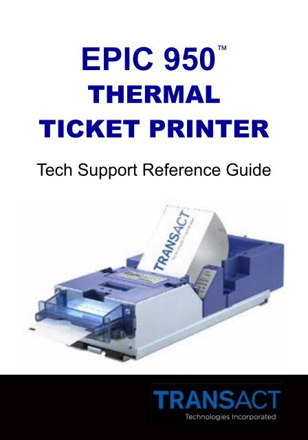
<strong>EPIC</strong> 950 <br />
THERMAL<br />
TICKET PRINTER<br />
Tech Support Reference Guide
2<br />
Contacting Information / Serial Plate Info<br />
<strong>TransAct</strong> Technologies, Inc. is the manufacturer of Ithaca<br />
brand POS and Banking receipt printers and the Epic brand<br />
gaming printers. 877.748.4222 | www.transact-tech.com<br />
When calling the toll free number above enter option 2 for<br />
Parts and RMA’s or enter option 3 for Technical Support.<br />
E-mail Technical Support at Techsupport@transact-tech.com<br />
Online RMA form http://www.transact-tech.com/tsg/rma.html<br />
Additional product support information can be found on our<br />
website under Support > Product Info > Epic 950.<br />
<strong>TransAct</strong> also maintains an FTP site for downloading documentation,<br />
utilities and firmware files. ftp://ftp.transacttech.com/<br />
USER ID: gaming | PASSWORD: CAs1no123<br />
Or at ftp://gaming:CAs1no123@ftp.transact-tech.com/<br />
Date Code identification:<br />
• The first letter denotes the month built, as follows:<br />
A = January, B = February, C = March,<br />
D = April, E = May, F = June, G = July,<br />
H = August, I = September, J = October,<br />
K = November & L = December<br />
• The two numbers<br />
denote the last two<br />
digits of the year<br />
built, as follows:<br />
04 = 2004<br />
05 = 2005<br />
06 = 2006.…<br />
Serial Plate Information<br />
Note: Standard printer warranty is 2 years from the build date.
Printing a Self-test Ticket<br />
Print a test ticket using the printer’s self-test procedure:<br />
Press and hold the FEED button for approximately 5 seconds,<br />
then release and the self-test ticket will then print.<br />
- Or -<br />
1. Un-rack the Inner<br />
Chassis.<br />
2. Open the Ticket Cover.<br />
Do not remove the<br />
currently loaded ticket.<br />
3. Press and hold the<br />
FEED button until the<br />
Open LED goes out,<br />
then release this button.<br />
4. Now close the Ticket<br />
Cover and the self-test<br />
ticket will then print.<br />
5. Close the Inner Chassis<br />
to resume normal<br />
operation.<br />
NOTE:<br />
Provides useful information<br />
regarding loaded firmware<br />
version and configured<br />
Baud Rate settings in addition<br />
to performing mechanical<br />
testing. Self-test<br />
Ticket<br />
3<br />
Printing a Self-test Ticket
4<br />
Printer Status and Bezel Light LED’s<br />
The printer has been outfitted with a LED panel system<br />
that provides the condition of the printer by using solid<br />
or blinking status LEDs to communicate status information.<br />
The following table lists the different LED states<br />
for specific printer conditions.<br />
Ready Paper Open<br />
Condition LED LED LED<br />
Fault<br />
LED<br />
Unit Ready On Off Off Off<br />
Cover Open On Off On Off<br />
Chassis Open On Off Blink Off<br />
Ticket Out On On Off Off<br />
Ticket Low On Blink Off Off<br />
Head Temp Error Blink Off Off Blink<br />
Paper Jam On Off Off Blink<br />
Ram Error 2-Blink Off Off On<br />
Boot Load Mode Blink Off Off On<br />
Config Mode Blink Off Off Off<br />
Steady<br />
Online and<br />
Ready<br />
Printer Status LED’s<br />
Bezel Status Lamp<br />
The printer’s bezel also displays certain printer status information.<br />
See the table below.<br />
Blinking<br />
Rapidly<br />
Ticket is<br />
being printed<br />
Ticket in<br />
ticket taken<br />
sensor<br />
Blinking<br />
Medium<br />
Ticket low<br />
Chassis<br />
open<br />
Cover open<br />
Blinking<br />
Slowly<br />
Ticket not<br />
loaded (TOF)<br />
Ticket jam<br />
error
Switch 1 is the<br />
furthest to the<br />
rear of the printer.<br />
The Active position<br />
is toward the<br />
outside edge of<br />
the printer.<br />
SW-1<br />
SW-2<br />
SW-3<br />
SW-4<br />
SW-5<br />
SW-6<br />
SW-7<br />
Switch 1<br />
Disabled<br />
Outside Edge of printer<br />
Switch 8<br />
Active<br />
Reserved and must be in the Disabled position. If activated,<br />
the printer will be held in reset.<br />
Configures Ticket Low. The Disabled position prevents<br />
ticket low from being detected.<br />
Activates Demo mode. It must be in the Disabled position<br />
for normal operation.<br />
Activates the Error log if enabled in file. This<br />
is useful for debugging but should not be on by default.<br />
Activates Com Save if enabled in file. This is<br />
also a debugging feature and will be used with future<br />
<strong>TransAct</strong> tools to help debug printer operations.<br />
Reserved<br />
DIP Switch Settings<br />
Activates the Smart Suite features. Must be active to<br />
use the status features of the Bench Test utility.<br />
Must be active on Bally Alpha platforms with 3.17OS or<br />
grater or if you receive constant “Printer COMM Error”.<br />
5<br />
SW-8<br />
Activates 2-color operation (color ticket media required)<br />
DIP Switch Settings
6<br />
Game Interface Options<br />
Serial (RS-232 )<br />
• Communication board #95-04998L (14-pin connector)<br />
• Powered through the game<br />
Netplex<br />
• Communication board #95-05001L (10-pin connector)<br />
• Powered through 8-pin pigtail connector<br />
USB<br />
• Communication board #95-05007L (4-pin connector)<br />
• Powered through the game<br />
IGT USB/Netplex<br />
• Communication board #95-05472L (4-pin USB connector<br />
and 6-pin Netplex connection)<br />
• Powered through a 4-pin Molex connector<br />
Netplex<br />
Serial<br />
USB<br />
Netplex/USB<br />
Note: The Inner Chassis is compatible with all firmware versions
Printer Firmware Versions<br />
Firmware Naming Convention:<br />
Each firmware file is named with a prefix and number that<br />
signify specific information about the firmware in the file. The<br />
Family Mask is indicative of backwards compatible firmware.<br />
Firmware Prefix - Interface Type or Usage<br />
F XXX xx Factory Test - Must be re-flashed!<br />
D XXX xx Demo - prints demo tickets w/o host PC<br />
S XXX xx Serial - <strong>TransAct</strong> Protocol (Serial PCB)<br />
N XXX xx Netplex Protocol - WMS (Serial PCB)<br />
V XXX xx Netplex Protocol - IGT (Netplex PCB)<br />
U XXX xx USB - <strong>TransAct</strong> Protocol (USB PCB)<br />
IUN XXX xxxx IGT Universal Netplex (Netplex/USB PCB)<br />
IUU XXX xxxx IGT Universal USB (Netplex/USB PCB)<br />
Firmware Revision<br />
Firmware Family Mask<br />
Obtaining Printer Firmware:<br />
Firmware files are available for download from the<br />
<strong>TransAct</strong> Gaming FTP site (see page #2). After logging in,<br />
browse to the Epic 950/Firmware folder, select the interface type<br />
and firmware version to download.<br />
<strong>TransAct</strong> Firmware Disclaimer:<br />
The firmware within all gaming ticket printers are subject to<br />
regulatory approval. It is the casino’s responsibility to ensure<br />
that only approved firmware for the specific game platform is<br />
installed to avoid potential fines imposed by the regulatory body.<br />
Please contact the game manufacture and/or regulatory agency<br />
to confirm the approval status prior to using any new printer<br />
firmware version/s in your games.<br />
7<br />
Printer Firmware Versions
8<br />
Download and Test Hardware<br />
Required download hardware:<br />
To download printer firmware into an Epic 950 printer requires<br />
some additional hardware available for purchase from <strong>TransAct</strong><br />
or our distributors. 100-06693L “Single-download Kit” includes<br />
the items below whereas 100-06935L includes an Outer Chassis<br />
with a Serial interface needed to dock and power the printer.<br />
imPort:<br />
The Epic 950 printer features an imPort<br />
firmware and graphics download port. This<br />
port uses a 4-pin Molex connector with an<br />
RS-232 interface for connecting with a PC at<br />
a fixed Baud Rate of 115,200 bps.<br />
Warning: Do not plug power into imPort<br />
Making the connections:<br />
Attach the hardware included in the Single Download Kit as<br />
shown above. Note: Power can be supplied to the printer from; a<br />
slot machine, from the 4-pin power connector into a USB I/F<br />
PCB, or via the Communication/Power Adaptor when attached<br />
to an Outer Chassis with a 14-pin Serial interface connector.
Flashing Printer Firmware<br />
Enter printer Boot Load mode:<br />
1. Un-rack and open the printer’s top cover as shown above<br />
2. Hold the FEED button while applying power to the printer<br />
3. Verify status LED panel - READY > Flashing & FAULT > ON<br />
Note: The printer will reset and print a test ticket when download<br />
completes if you rack-in, close top cover with tickets loaded.<br />
The Single<br />
Download utility<br />
Download.exe is<br />
available on the<br />
CD included with<br />
the Download Kit<br />
or from the FTP<br />
site (see page #2<br />
for details)<br />
Utility one-time setup:<br />
1. Select the assigned COMM Port number from the pull down<br />
2. Right click on the utility’s ti tle bar and checkmark XON/XOFF<br />
3. Slide the “Serial Performance” slider to 115,200 bps<br />
Flashing printer firmware:<br />
1. Click “Get Printer Info” button. The boxes below the button<br />
should populate. Also verifies bidirectional communications<br />
2. Click “Select file to Download” button and choose a firmware<br />
3. Click “Download Now” button to begin downloading<br />
4. Wait until 100% Flash Update DONE is displayed<br />
Caution: watch the LEDS on the printer ... when the firmware<br />
download operation is completed only the READY LED will<br />
be flashing a short blink once every second<br />
5. Close the cover and chassis and power cycle the printer<br />
9<br />
Flashing Printer Firmware
10<br />
Racking/Un-racking the Inner Chassis<br />
To remove the Inner Chassis:<br />
• Pull on the Ticket Cover to release the rear detents, pulling<br />
the Inner Chassis towards you until its latches catch the forward<br />
detent slots.<br />
• Push the Inner Chassis back in slightly, pull on the Release<br />
Lever and pull forward on the Inner Chassis to undock it from<br />
the Outer Chassis.<br />
To return the Inner Chassis:<br />
(see warning before racking)<br />
• Align the base of the Inner Chassis with the outer walls of the<br />
Outer Chassis, seating it within side walls A and B as shown.<br />
Make certain it’s straight so the inner chassis<br />
doesn’t damage the flex cable.<br />
• While pulling outwards on the Release Lever, slide the Inner<br />
Chassis towards the rear of the Outer Chassis. Push the<br />
Inner Chassis all the way to the back until it stops. When fully<br />
seated, the front metal plate of the inner chassis and the<br />
front left edge of the outer chassis are flush.<br />
Warning: Interconnect PC Board<br />
Assembly must be latched in position shown<br />
Check by trying to move the board by<br />
hand prior to racking.<br />
MAKE SURE IT IS LATCHED
Cleaning instructions:<br />
Preventive Maintenance<br />
1. Remove Inner Chassis as shown above<br />
2. Open top cover all the way to allow airflow between printhead<br />
and platen roller<br />
3. Remove any loose particles using compressed air<br />
4. Clean ticket burst area (under top cover) with a lint free cloth<br />
5. Supply power to the printer ether by reinstalling it back into a<br />
game or using the Download Kit’s power supply<br />
6. Open cleaning card pouch and remove cleaning card<br />
7. Insert cleaning card into feed path while applying some tension<br />
thereby cleaning the entire surface of the platen roller<br />
8. Open the top cover and remove the cleaning card<br />
9. Repeat process if necessary<br />
10. Properly dispose of used cleaning card<br />
Waffletechnology cleaning cards with cutout notches:<br />
Insert cleaning card into feed path with the notches towards the<br />
leading edge and use the FEED button to feed it through 2x.<br />
Warnings:<br />
IPA solvents can damage rubber rollers with frequent use.<br />
<strong>TransAct</strong> recommends a maximum usage of 2x annually.<br />
The thermo print-head’s life can be reduced with excessive<br />
friction. When cleaning the component directly, <strong>TransAct</strong> recommends<br />
using an IPA solvent on a non abrasive lint free cloth.<br />
Purchasing cleaning cards:<br />
Cleaning cards are available through <strong>TransAct</strong>.<br />
Description:<br />
<strong>TransAct</strong> Part Number:<br />
2.5"x6" Cleaning Card (qty25) 100-03322<br />
11<br />
Preventive Maintenance
12<br />
Sensors and Switches<br />
Ticket Low Sensor<br />
• Optically senses when 5-10 tickets remain in ticket supply<br />
bucket<br />
• Reports ticket low to game in status byte<br />
• Verify with Game Manufacturer how status byte is managed<br />
Top of Form Sensor/Ticket Out Sensor<br />
• Senses and aligns to black dot on right edge of ticket<br />
Ticket Taken Sensor<br />
• Used to determine when customer has removed the printed<br />
ticket<br />
Audible Alarm<br />
• The Audible Alarm will activate upon printer reset. Other<br />
alarms are under control of the game
Chassis Open Sensor<br />
• Located on Main Controller Board<br />
• Determines if printer Inner Chassis is racked out or “open”<br />
Ticket Burst Sensor<br />
• The Ticket Burst Sensor is used to verify that the ticket perforations<br />
have been separated during the burst operation<br />
Cover Open Switch<br />
• The Cover Open Switch, when activated, returns a cover<br />
open status to the host and inhibits the ticket printing operation<br />
until the Ticket Cover is closed<br />
13<br />
Sensors and Switches
14<br />
Troubleshooting<br />
Problem<br />
Ticket jam<br />
Bad print<br />
quality<br />
No LEDs<br />
Poor Color<br />
Solution<br />
• Open ticket cover to clear jam in burst<br />
chamber<br />
• Clean print head<br />
• Check flex cable connections<br />
• Refer to Printer Status LED section for<br />
LED status errors<br />
• Check for two color ticket stock<br />
• Check dipswitch position 8 (color active<br />
“ON”)<br />
Main Controller Board Connections — see figure 1<br />
Fig. 1
Installation:<br />
Flex Cable Replacement<br />
When installing the cable into the Outer Chassis, make the<br />
rear connection first. Then create a loop in the cable so that it<br />
can be easily slipped over the clip (A) closest to the connector,<br />
then repeat for remaining clips. Release the sliding connector<br />
board’s latches by lifting up on the two levers and push<br />
the board towards the rear to allow enough slack to mate the<br />
front connection. Now mate the front connection to the sliding<br />
board and pull the sliding board forward until it is firmly latched.<br />
Warning: If reinstalling a used cable, care must be taken to<br />
insure that the cable’s bow protrudes in the direction as<br />
shown in Figure 2 and when installed, it should look like (C).<br />
Description:<br />
<strong>TransAct</strong> Part Number:<br />
Flex Cable<br />
98-06499L<br />
B<br />
A<br />
C<br />
Fig. 1<br />
Fig. 2<br />
15<br />
Flex Cable Replacement
16<br />
Notes
17<br />
Notes
Technical Support: 1.877.748.4222<br />
100-00971.0806