If Preferred -- Download The Entire Booklet - Spears Manufacturing ...
If Preferred -- Download The Entire Booklet - Spears Manufacturing ...
If Preferred -- Download The Entire Booklet - Spears Manufacturing ...

You also want an ePaper? Increase the reach of your titles
YUMPU automatically turns print PDFs into web optimized ePapers that Google loves.
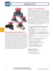
Engineering & Design Data<br />
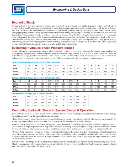
Hydraulic Shock<br />
Hydraulic shock is the rapid increase in pressure due to a shock wave produced by a sudden change in system fluid velocity. <strong>If</strong><br />
uncontrolled or insufficient pressure rated piping is used, these pressure surges can easily burst pipe and break valves or fittings.<br />
<strong>The</strong> term “water hammer” commonly used is derived from the sounds produced, but it is the hydraulic shock vibrations that can be<br />
damaging to piping systems. This is typically the result of sudden starting or stopping of a flowing column of liquid, such as water.<br />
Energy from the momentum of water in motion is converted to pressure when the flow is abruptly halted. A shock wave is produced<br />
that travels through the piping until it is stopped and bounces back to the original obstruction. This instantaneous shock to the system<br />
can lead to excessively high pressures. Hydraulic shock is frequently produced by rapid valve opening and closing, pumps starting<br />
and stopping, or even from a high speed wall of water hitting a change of direction fitting, such as an elbow. <strong>The</strong> effect is greater as<br />
piping systems is longer, the velocity change is greater and closing time is shorter.<br />
Evaluating Hydraulic Shock Pressure Surges<br />
An indication of the maximum surge pressure relative to velocity changes is essential in estimating the pressure rating requirements<br />
in designing a piping system. <strong>The</strong> following chart gives the maximum surge pressure at velocities of 1, 5 and 10 feet per second for<br />
different sizes of pipe, based on instantaneous valve closure in a PVC system. While listed, 10 feet per second is not recommended<br />
and is shown for comparative purposes. Velocity is best held to a maximum of 5 feet per second in plastic systems.<br />
Schedule 40 Pipe Pressure Surge (psi) at Different Velocities<br />
Size 1/2 3/4 1 1-1/4 1-1/2 2 2-1/2 3 4 6 8 10 12<br />
1 ft/sec 27.3 24.6 23.8 21.6 20.5 18.8 19.7 18.4 16.9 15.1 14.2 13.5 13.0<br />
5 ft/Sec 136.3 123.2 119.1 108.1 102.6 94.2 98.5 91.8 84.5 75.4 70.8 67.4 65.2<br />
10 ft/sec 272.7 246.3 238.2 216.3 205.1 188.3 196.9 183.5 169.0 150.9 141.6 134.8 130.5<br />
"<br />
Schedule 80 Pipe Pressure Surge (psi) at Different Velocities<br />
Size 1/2 3/4 1 1-1/4 1-1/2 2 2-1/2 3 4 6 8 10 12<br />
1 ft/sec 32.2 29.2 28.0 25.5 24.3 22.6 23.2 21.8 20.3 18.9 17.8 17.3 17.1<br />
5 ft/Sec 161 145.8 139.9 127.7 121.7 113.1 115.8 109.1 101.6 94.4 88.8 86.6 85.5<br />
10 ft/sec 322 291.7 279.9 255.4 243.4 226.2 231.7 218.1 203.1 188.9 177.6 173.1 171.0<br />
"<br />
SDR Pipe Pressure Surge (psi) at Different Velocities<br />
SDR 13.5 14 17 18 21 25 26 32.5 41<br />
1 ft/sec 20.2 19.8 17.9 17.4 16.0 14.7 14.4 12.8 11.4<br />
5 ft/Sec 101.0 99.1 89.5 86.9 80.2 --- 71.9 64.1 57.0<br />
10 ft/sec 201.9 198.1 179.0 173.8 160.4 146.7 143.7 128.2 113.9<br />
"<br />
Controlling Hydraulic Shock in System Design & Operation<br />
Since hydraulic shock is a function of speed, mass and time, there are several ways to prevent, minimize or eliminate system damage<br />
by limiting or controlling the magnitude of pressure surges.<br />
• Limit Fluid Velocity – one of the safest surge control techniques in plastic systems is to limit fluid velocities to a maximum of 5 ft./<br />
second. Attempt to balance system operation flow demands and the magnitude of velocity variations.<br />
• Control Valve Closing Time – avoid rapid opening and closing. Pneumatic or electric actuation may be considered for greater control.<br />
Use of multi-turn or gear operated valves may also be beneficial in slowing valve opening and closing. When all valves and controls<br />
are properly sized and adjusted, surges generated by changes in pump flows and demands can be reduced to non-harmful levels.<br />
• Control Pump Operation – operate the system to maintain uniform pump flow rates. Use slow starting pumps where long runs and<br />
larger diameters are downstream. Where possible, partially close discharge valves to minimize volume when starting pumps, until<br />
lines are completely filled. Air chambers or surge relief tanks in conjunction with pressure regulating and surge relief valves can be<br />
used at pumping stations.<br />
• Check Valves – installing a check valve in pump discharge lines will aid in keeping the line full. Be careful in selecting check valves.<br />
Check valves operate on flow reversal and can be rapid closing. Spring or lever assisted swing check valves can reduce hydraulic<br />
shock by avoiding “slamming” the valve closed.<br />
20