If Preferred -- Download The Entire Booklet - Spears Manufacturing ...
If Preferred -- Download The Entire Booklet - Spears Manufacturing ...
If Preferred -- Download The Entire Booklet - Spears Manufacturing ...

You also want an ePaper? Increase the reach of your titles
YUMPU automatically turns print PDFs into web optimized ePapers that Google loves.
Installation<br />
Transition Joints &<br />
Specialty Fittings<br />
PVC and CPVC pipe can be connected to steel, copper, brass,<br />
other metals and other plastic materials using a variety of transition<br />
fittings including unions, compression fittings, special<br />
reinforced adapters, flanged joints and grooved mechanical<br />
coupling joints.<br />
Do not use regular PVC or CPVC female threaded fittings for<br />
connection to metal male threads. <strong>Spears</strong> ® Special Reinforced<br />
(SR) female plastic threaded fittings are excellent for plastic to<br />
metal transitions. Unlike conventional plastic female adapters,<br />
these fittings incorporate the use of a stainless steel restraining<br />
collar located on the exterior of the FIPT threads of the adapter.<br />
This design allows direct connection to male metal threads<br />
without the need for pressure de-rating normally associated<br />
with conventional FIPT adapters, as the radial stress generated<br />
by thread engagement is contained. Other PVC/CPVC adapter<br />
fittings with brass or steel threads can also be used for transition<br />
to metal male threads.<br />
<strong>If</strong> regular non-reinforced plastic threads must be transitioned<br />
to metal threads, the recommended joint is to use male plastic<br />
threads into female metal threads.<br />
Underground Installation<br />
Underground piping must be installed in accordance with any<br />
applicable codes. Attention should be given to local pipe laying<br />
techniques applicable to area subsoil. This may provide insights<br />
to particular pipe bedding issues. <strong>The</strong> following information is<br />
applicable to solvent cement joining of PVC and CPVC piping<br />
as a general guide. Refer to Gasketed Pipe section for additional<br />
information on installation of gasketed pipe.<br />
Inspection: Before installation, PVC and CPVC piping products<br />
should be inspected for cuts, scratches, gouges or split<br />
ends. Damaged sections found must be cut-out and discarded.<br />
Trenching: <strong>The</strong> trench should be as narrow as possible while<br />
providing adequate width to allow convenient installation.<br />
Minimum trench widths may be utilized by joining pipe outside<br />
of the trench and lowering it into the trench after adequate joint<br />
strength has been achieved. Refer to solvent cement instructions<br />
for recommended joint set and cure time.<br />
Trench widths will have to be wider where pipe is joined in the<br />
trench or where thermal expansion and contraction is a factor.<br />
<strong>The</strong>rmoplastic pipe should ALWAYS be installed below the<br />
frost level according to local conditions. Pipe for conveying<br />
liquids susceptible to freezing should be buried no less than<br />
12" below the maximum frost level. Permanent lines subjected<br />
to heavy traffic should have a minimum cover of 24". For light<br />
traffic 12" to 18" is normally sufficient for small diameter pipe<br />
(typically < 3" diameter). With larger sizes, bearing stresses<br />
should be calculated to determine cover required.<br />
When it is installed beneath surfaces that are subject to heavy<br />
weight or constant traffic such as roadways and railroad tracks,<br />
thermoplastic piping should be run within a metal or concrete<br />
casing. Refer to Critical Collapse Pressure Ratings for additional<br />
information.<br />
<strong>The</strong> trench bottom should be continuous, relatively smooth<br />
and free of rocks. Where ledge rock, hardpan or boulders are<br />
encountered, it is necessary to pad the trench bottom using a<br />
minimum of four (4) inches of tamped earth or sand beneath the<br />
pipe as a cushion and for protection of the pipe from damage.<br />
Sufficient cover must be maintained to keep external stress<br />
levels below acceptable design stress. Reliability and safety of<br />
service is of major importance in determining minimum cover.<br />
Local, state and national codes may also govern.<br />
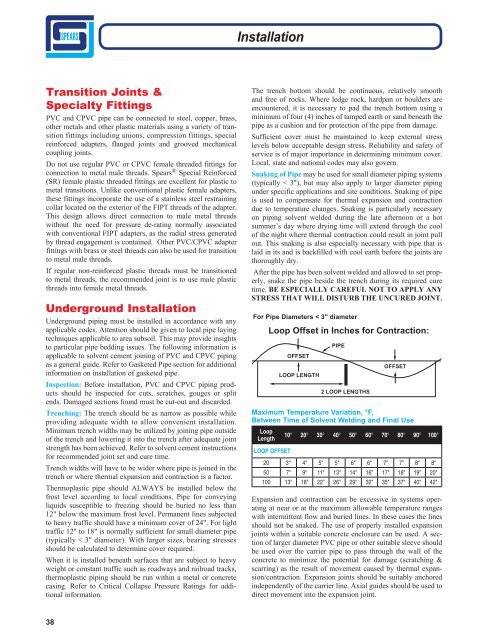
Snaking of Pipe may be used for small diameter piping systems<br />
(typically < 3"), but may also apply to larger diameter piping<br />
under specific applications and site conditions. Snaking of pipe<br />
is used to compensate for thermal expansion and contraction<br />
due to temperature changes. Snaking is particularly necessary<br />
on piping solvent welded during the late afternoon or a hot<br />
summer’s day where drying time will extend through the cool<br />
of the night where thermal contraction could result in joint pull<br />
out. This snaking is also especially necessary with pipe that is<br />
laid in its and is backfilled with cool earth before the joints are<br />
thoroughly dry.<br />
After the pipe has been solvent welded and allowed to set properly,<br />
snake the pipe beside the trench during its required cure<br />
time. BE ESPECIALLY CAREFUL NOT TO APPLY ANY<br />
STRESS THAT WILL DISTURB THE UNCURED JOINT.<br />
For Pipe Diameters < 3" diameter<br />
Loop Offset in Inches for Contraction:<br />
OFFSET<br />
LOOP LENGTH<br />
PIPE<br />
2 LOOP LENGTHS<br />
OFFSET<br />
Maximum Temperature Variation, °F,<br />
Between Time of Solvent Welding and Final Use<br />
Loop<br />
Length<br />
10° 20° 30° 40° 50° 60° 70° 80° 90° 100°<br />
LOOP OFFSET<br />
20 3" 4" 5" 5" 6" 6" 7" 7" 8" 8"<br />
50 7" 9" 11" 13" 14" 16" 17" 18" 19" 20"<br />
100 13" 18" 22" 26" 29" 32" 35" 37" 40" 42"<br />
Expansion and contraction can be excessive in systems operating<br />
at near or at the maximum allowable temperature ranges<br />
with intermittent flow and buried lines. In these cases the lines<br />
should not be snaked. <strong>The</strong> use of properly installed expansion<br />
joints within a suitable concrete enclosure can be used. A section<br />
of larger diameter PVC pipe or other suitable sleeve should<br />
be used over the carrier pipe to pass through the wall of the<br />
concrete to minimize the potential for damage (scratching &<br />
scarring) as the result of movement caused by thermal expansion/contraction.<br />
Expansion joints should be suitably anchored<br />
independently of the carrier line. Axial guides should be used to<br />
direct movement into the expansion joint.<br />
38