If Preferred -- Download The Entire Booklet - Spears Manufacturing ...
If Preferred -- Download The Entire Booklet - Spears Manufacturing ...
If Preferred -- Download The Entire Booklet - Spears Manufacturing ...

Create successful ePaper yourself
Turn your PDF publications into a flip-book with our unique Google optimized e-Paper software.
Plastic<br />
Pipe<br />
Handbook<br />
SPEARS ® PLASTIC PIPE HANDBOOK • ENGINEERING GUIDE<br />
ENGINEERING GUIDE<br />
IP-4-0112
Providing customers with the best of what they need, when they need it has always<br />
been central to the SPEARS ® philosophy. Backed by over 40 years of both product<br />
and process development experience, SPEARS ® has become one of the leading manufacturers<br />
of thermoplastic valves, fittings, and piping system components including<br />
a full assortment of solvent cements and accessories. Innovative product designs and<br />
improvements, new technologies, and a fully integrated manufacturing system are all a<br />
part of SPEARS ® ongoing commitment to Quality, Satisfaction, and Service.<br />
<strong>The</strong> information contained in this publication is based on current information and product design at the time of publication and is subject<br />
to change without notification. Our ongoing commitment to product improvement may result in some variations. No representations,<br />
guarantees or warranties of any kind are made as to its accuracy, suitability for particular application or results to be obtained therefrom.<br />
For information not contained herein, please contact <strong>Spears</strong> ® Technical Services Department [West Coast: (818) 364-1611 — East Coast:<br />
(678) 985-1263]. Reproduction of this publication in whole or in part is prohibited without the authorized consent of <strong>Spears</strong> ® <strong>Manufacturing</strong><br />
Company, Sylmar, California.<br />
© Copyright 2012 <strong>Spears</strong> ® <strong>Manufacturing</strong> Company. All Rights Reserved. Printed in the United States of America.
Table of Contents<br />
• General Information .........................................................................................................1<br />
• Purpose of this Manual ..................................................................................................1<br />
• <strong>Spears</strong> ® PVC & CPVC Materials ..................................................................................1<br />
• Physical Properties of PVC & CPVC Pipe......................................................................2<br />
• Dimensions & Pressure Ratings .....................................................................................3<br />
• PVC Pipe .......................................................................................................................4<br />
• CPVC Industrial Pipe .....................................................................................................5<br />
• Temperature De-Rating .................................................................................................6<br />
• Engineering and Design ..................................................................................................7<br />
• Flow Velocity & Friction Loss.........................................................................................7<br />
• Hydraulic Shock .............................................................................................................20<br />
• Evaluating Hydraulic Shock Pressure Surges ...............................................................20<br />
• Controlling Hydraulic Shock in System Design & Operation .........................................20<br />
• <strong>The</strong>rmal Expansion & Contraction .................................................................................21<br />
• Calculating Linear Movement Caused by <strong>The</strong>rmal Expansion .....................................22<br />
• Compensating for Movement Caused by <strong>The</strong>rmal Expansion/Contraction ..................22<br />
• <strong>The</strong>rmal Stress ..............................................................................................................23<br />
• Thrust Blocking ..............................................................................................................24<br />
• Critical Collapse Pressures ...........................................................................................25<br />
• Temperature Limitations ................................................................................................25<br />
• Weatherability ................................................................................................................25<br />
• Installation .........................................................................................................................26<br />
• Handling & Storage .......................................................................................................26<br />
• Plastic Piping Tools ........................................................................................................26<br />
• Joining Methods - Solvent Cement Welding .................................................................26<br />
• Basic Solvent Cement Joints .........................................................................................27<br />
• Fitting & Joining Preparation .........................................................................................27<br />
• Set and Cure Times .......................................................................................................28<br />
• Special Considerations for Working with Solvent Cement Welding ..............................29<br />
• Supplemental Information on Solvent Cementing .........................................................31<br />
• Joining Method - Threaded Connections ......................................................................33<br />
• Joining Method - Flanged Connections .........................................................................34<br />
i
Table of Contents<br />
• Joining Method - Mechanical Groved Couplings ...........................................................34<br />
• Joining Method - Gasketed Pipe ...................................................................................35<br />
• Field Assembly of Gasketed Joint .................................................................................35<br />
• Deflection .......................................................................................................................36<br />
• Assembly Instructions ....................................................................................................37<br />
• Transition Joints & Specialty Fittings .............................................................................38<br />
• Underground Installation ...............................................................................................38<br />
• Above Ground Installation .............................................................................................39<br />
• Hangers & Supports ......................................................................................................39<br />
• Special Pipe - <strong>Spears</strong> ® PVC Clear ..................................................................................45<br />
• Special Pipe - <strong>Spears</strong> ® Low Extractable PVC ...............................................................47<br />
• Special Pipe - <strong>Spears</strong> ® LabWaste CPVC Corrosive Waste Drainage ......................51<br />
• Special Pipe - <strong>Spears</strong> ® FlameGuard ® CPVC Fire Sprinkler Piping Systems .............52<br />
• Special Pipe - <strong>Spears</strong> ® CTS CPVC Piping Systems .....................................................53<br />
• <strong>Spears</strong> ® PVC & CPVC Duct .............................................................................................57<br />
• Chemical Resistance Data for Pressure Piping ............................................................63<br />
• Chemical Resistance Data for LabWaste ® Drainage System ......................................70<br />
• Industry Standards & Test Methods ...............................................................................74<br />
• Industry Piping Formulas ................................................................................................76<br />
• Basic Conversions ...........................................................................................................78<br />
• Glossary of Terms ............................................................................................................82<br />
• <strong>Spears</strong> ® Product Line Overview .....................................................................................88<br />
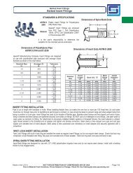
• PVC & CPVC Schedule 80 Special Reinforced Fittings ...............................................94<br />
• Limited Lifetime Warranty ................................................................... Inside Back Cover<br />
ii
General Information<br />
Purpose of this Manual<br />
This manual is intended as resource for use by specification engineers, installers, and users in the selection, design and installation<br />
of PVC and CPVC systems installed using <strong>Spears</strong> ® or other pipe products. All information contained within this manual<br />
is considered vital to obtain proper system performance and must be read and fully understood before attempting to install these<br />
products. <strong>If</strong> you have any questions about the safe and proper installation of these products, contact <strong>Spears</strong> ® <strong>Manufacturing</strong><br />
Company, 15853 Olden Street, Sylmar CA 91342 USA, Telephone (818) 364-1611.<br />
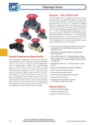
<strong>Spears</strong> ® PVC and CPVC Materials<br />
PVC<br />
Polyvinyl Chlorides (PVC) is one of the most widely used<br />
plastic piping materials. PVC is environmentally sound, provides<br />
long service life, is light weight and easy to install, has<br />
superior corrosion resistance, is cost effective, and widely<br />
accepted by codes. PVC pipe is manufactured by extrusion<br />
and PVC fittings are manufactured by injection molding<br />
or fabrication. PVC is an amorphous thermoplastic material<br />
with physical properties that make it suitable for a wide<br />
variety of pressure and non-pressure applications and can be<br />
compounded for optimum performance. PVC pipe and fittings<br />
are used for drain-waste-vent (DWV), sewers, water<br />
mains, water service lines, irrigation, conduit, and various<br />
industrial installations.<br />
<strong>Spears</strong> ® high quality PVC compounds give optimum chemical<br />
and corrosion resistance with a full range of pressure<br />
handling capabilities. <strong>Spears</strong> ® PVC materials are certified<br />
by NSF International to applicable standards, including NSF<br />
Standard 61 for use in potable water service and to ASTM<br />
STD D1784, Rigid Poly (Vinyl Chloride) (PVC) Compounds<br />
and Chlorinated Poly (Vinyl Chloride) (CPVC) Compounds<br />
that specifies Cell Classification for minimum physical property<br />
requirements. <strong>The</strong>se include resin type, impact strength,<br />
tensile strength, modulus of elasticity in tension, heat deflection<br />
temperature and flammability. <strong>Spears</strong> ® minimum PVC<br />
Cell Classification is 12454 for rigid (unplasticized) PVC.<br />
<strong>The</strong> ASTM Type and Grade is PVC Type I, Grade I and the<br />
typical long and short term strength designation of material<br />
for pressure piping is PVC 1120.<br />
See Industry Standards and Test Methods, Physical Properties<br />
and Chemical Resistance sections for additional information.<br />
<strong>Spears</strong> ® PVC Pipe & Systems Product Lines<br />
EverTUFF ® Industrial Schedule 80 Pressure Pipe & Fittings<br />
<strong>Spears</strong> ® Clear PVC Schedule 40 & Schedule 80 Pipe & Fittings<br />
<strong>Spears</strong> ® Low Extractable Ultra Pure Water Piping & Fittings<br />
<strong>Spears</strong> ® PVC Duct & Fittings<br />
<strong>Spears</strong> ® PVC Double Containment Pipe & Fittings<br />
<strong>Spears</strong> ® Supplemental PVC Fittings, Valves & Accessories<br />
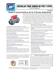
CPVC<br />
Chlorinated polyvinyl chloride (CPVC) is created by post<br />
chlorination of the PVC polymer. This produces up to a 60°F<br />
higher heat handling capability than PVC and greater fire<br />
resistance, plus a broad range of chemical resistance. CPVC<br />
is excellent for use in process piping, hot and cold water<br />
service, corrosive waste drainage and other elevated temperature<br />
applications. CPVC provides relatively low cost<br />
compared to alternative materials for similar use. CPVC<br />
pipe is manufactured by extrusion and CPVC fittings are<br />
manufactured by injection molding or fabrication. <strong>Spears</strong> ®<br />
produces a variety of CPVC pipe, fittings, valves, system<br />
accessories and specialty systems.<br />
<strong>Spears</strong> ® high quality CPVC compounds give optimum chemical<br />
and corrosion resistance with a full range of pressure<br />
handling capabilities. <strong>Spears</strong> ® CPVC materials are certified<br />
by NSF International to applicable standards, including<br />
NSF Standard 61 for use in potable water service and to<br />
ASTM STD D1784, Rigid Poly (Vinyl Chloride) (PVC)<br />
Compounds and Chlorinated Poly (Vinyl Chloride) (CPVC)<br />
Compounds that specifies Cell Classification for minimum<br />
physical property requirements. <strong>The</strong>se include resin type,<br />
impact strength, tensile strength, modulus of elasticity in<br />
tension, heat deflection temperature and flammability.<br />
<strong>Spears</strong> ® minimum CPVC Cell Classification is 23447 for<br />
rigid (unplasticized) CPVC.<br />
<strong>The</strong> ASTM Type and Grade is CPVC Type IV Grade I and<br />
the typical long and short term strength designation of<br />
material for pressure piping is CPVC 4120.<br />
See Industry Standards and Test Methods, Physical Properties<br />
and Chemical Resistance sections for additional information.<br />
<strong>Spears</strong> ® CPVC Pipe & Systems Product Lines<br />
EverTUFF ® Industrial Schedule 40 & Schedule 80 CPVC<br />
Pressure Pipe & Fittings<br />
EverTUFF ® CTS CPVC Hot and Cold Water Plumbing<br />
Distribution Pipe & Fittings<br />
LabWaste CPVC Corrosive Waste Drainage System Pipe<br />
& Fittings<br />
FlameGuard ® CPVC Fire Sprinkler Products Pipe & Fittings<br />
<strong>Spears</strong> ® CPVC Duct & Fittings<br />
<strong>Spears</strong> ® CPVC Double Containment Pipe & Fittings<br />
<strong>Spears</strong> ® Supplemental CPVC Fittings, Valves & Accessories<br />
1
Physical Properties of PVC & CPVC Pipe<br />
GENERAL PVC Value CPVC Value Test Method<br />
Cell Classification 12454 23447 ASTM D 1784<br />
Maximum Service Temp. 140°F 200°F<br />
Color White, Dark Gray Medium Gray<br />
Specific Gravity, (g/cu.cm @ 73°F) 1.41 1.51 ASTM D 792<br />
Water Absorption % increase 24 hrs @ 25°C 0.05 0.03 ASTM D 570<br />
Hardness, Rockwell 110 - 120 117 - 119 ASTM D 785<br />
Poisson's Ratio @ 73°F 0.410 0.370<br />
MECHANICAL<br />
Tensile Strength, psi @ 73°F 7,450 7,900 ASTM D 638<br />
Tensile Modulus of Elasticity, psi @ 73°F 420,000 426,000 ASTM D 638<br />
Flexural Strength, psi @ 73°F 14,450 15,000 ASTM D 790<br />
Flexural Modulus, psi @ 73°F 360,000 360,000 ASTM D 790<br />
Compressive Strength, psi @ 73°F 9,600 10,000 ASTM D 695<br />
Izod Impact, notched, ft-lb/in @ 73°F 0.75 2.9 ASTM D 256<br />
THERMAL<br />
Coefficient of Linear Expansion (in/in/°F) 2.9 x 10 -5 3.2 x 10 -5 ASTM D 696<br />
Coefficient of <strong>The</strong>rmal Conductivity ASTM C 177<br />
Calories • cm/second • cm2 • °C 3.5 x 10 -4 3.27 x 10 -4<br />
BTU • inches/hour • Ft.2 • °F 1.02 0.95<br />
Watt/m/K 0.147 0.137<br />
Heat Deflection Temperature<br />
Under Load (264 psi, annealed) 170 235 ASTM D 648<br />
ELECTRICAL<br />
Dielectric Strength, volts/mil 1,413 1,250 ASTM D 149<br />
Dielectric Constant, 60Hz, 30°F 3.70 3.70 ASTM D 150<br />
Volume Resistivity, ohm/cm @ 95°C 1.2 x 10¹² 3.4 x 10¹² ASTM D 257<br />
<strong>Spears</strong>® PVC & CPVC Pipe is non-electrolytic<br />
FIRE PERFORMANCE<br />
Flammability Rating V-0 V-0, 5VB, 5VA UL-94<br />
Flame Spread Index
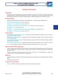
Dimensions & Pressure Ratings<br />
PVC & CPVC pipe is produced in several different outside diameters, sizes and dimensions for different applications. Different<br />
classifications based on outside diameter are not interchangeable, but can often be connected with specialty adapter fittings.<br />
Basic Pipe Sizing Classifications Based on Outside Diameter<br />
• Iron Pipe Size (IPS) - PVC & CPVC Pressure Pipe and Drainage Waste & Vent DWV pipe, forms one of the most widely used<br />
sizing classifications including Schedule 40, 80 & 120 pipe and Class pipe in various Standard Dimension Ratios (SDR); plus<br />
several specialty piping products such as <strong>Spears</strong> ® FlameGuard ® CPVC Fire Sprinkler Systems, LabWaste CPVC Corrosive<br />
Waste Drainage Systems, and Low Extractable PVC Systems for Ultra Pure Water.<br />
• Plastic Irrigation Pipe (PIP) – PVC for agricultural irrigation<br />
• Copper Tube Size (CTS) – CPVC for Hot & Cold Waste Distribution<br />
• Plastic Sewer Main (Type PSM) – PVC for gravity sewer mains<br />
• AWWA C900/905 – PVC with Cast Iron O.D. for municipal water systems<br />
<strong>The</strong> following Pipe Dimension Reference chart is for quick reference to some of the commonly used sizing classifications and<br />
nominal sizes. <strong>The</strong> following pages give additional detail for widely used PVC & CPVC pipe in IPS and CTS sizes.<br />
Pipe Dimension Reference Chart<br />
Pipe Type<br />
O.D. Size<br />
SDR<br />
4"<br />
6"<br />
8"<br />
10"<br />
12"<br />
14"<br />
15"<br />
16"<br />
18"<br />
20"<br />
21"<br />
24"<br />
O.D.<br />
I.D.<br />
Wall<br />
PSI<br />
O.D.<br />
I.D.<br />
Wall<br />
PSI<br />
O.D.<br />
I.D.<br />
Wall<br />
PSI<br />
O.D.<br />
I.D.<br />
Wall<br />
PSI<br />
O.D.<br />
I.D.<br />
Wall<br />
PSI<br />
O.D.<br />
I.D.<br />
Wall<br />
PSI<br />
O.D.<br />
I.D.<br />
Wall<br />
PSI<br />
O.D.<br />
I.D.<br />
Wall<br />
PSI<br />
O.D.<br />
I.D.<br />
Wall<br />
PSI<br />
O.D.<br />
I.D.<br />
Wall<br />
PSI<br />
O.D.<br />
I.D.<br />
Wall<br />
PSI<br />
O.D.<br />
I.D.<br />
Wall<br />
PSI<br />
LH<br />
PIP<br />
91<br />
4.130<br />
4.000<br />
.065<br />
43<br />
6.140<br />
6.000<br />
.070<br />
43<br />
8.160<br />
7.984<br />
.088<br />
43<br />
10.200<br />
9.980<br />
.110<br />
43<br />
12.240<br />
11.975<br />
.132<br />
43<br />
14.280<br />
14.000<br />
.140<br />
43<br />
15.300<br />
14.970<br />
.165<br />
43<br />
80<br />
PIP<br />
51<br />
4.130<br />
3.968<br />
.081<br />
80<br />
6.140<br />
5.898<br />
.121<br />
80<br />
8.160<br />
7.840<br />
.160<br />
80<br />
10.200<br />
9.800<br />
.200<br />
80<br />
12.240<br />
11.760<br />
.240<br />
80<br />
14.280<br />
13.720<br />
.280<br />
80<br />
15.300<br />
14.700<br />
.300<br />
80<br />
100<br />
PIP<br />
41<br />
4.130<br />
3.928<br />
.101<br />
100<br />
6.140<br />
5.840<br />
.150<br />
100<br />
8.160<br />
7.762<br />
.199<br />
100<br />
10.200<br />
9.702<br />
.249<br />
100<br />
12.240<br />
11.642<br />
.299<br />
100<br />
14.280<br />
13.584<br />
.348<br />
100<br />
15.300<br />
14.550<br />
.375<br />
100<br />
125<br />
PIP<br />
32.5<br />
4.130<br />
3.876<br />
.127<br />
125<br />
6.140<br />
5.762<br />
.189<br />
125<br />
8.160<br />
7.658<br />
.251<br />
125<br />
10.200<br />
9.572<br />
.314<br />
125<br />
12.240<br />
11.486<br />
.377<br />
125<br />
14.280<br />
13.402<br />
.439<br />
125<br />
15.300<br />
14.358<br />
.471<br />
125<br />
CL 63<br />
IPS<br />
64<br />
4.500<br />
4.360<br />
.070<br />
63<br />
6.625<br />
6.417<br />
.104<br />
63<br />
8.625<br />
8.355<br />
.135<br />
63<br />
10.750<br />
10.414<br />
.168<br />
63<br />
12.750<br />
12.352<br />
.199<br />
63<br />
CL 100<br />
IPS<br />
41<br />
4.500<br />
4.280<br />
.110<br />
100<br />
6.625<br />
6.301<br />
.162<br />
100<br />
8.625<br />
8.205<br />
.210<br />
100<br />
10.750<br />
10.226<br />
.262<br />
100<br />
12.750<br />
12.128<br />
.311<br />
100<br />
SEWER<br />
PSM<br />
35<br />
4.215<br />
3.89<br />
0.125<br />
117.5<br />
6.275<br />
5.742<br />
0.18<br />
117.5<br />
8.4<br />
7.665<br />
.024<br />
117.5<br />
10.5<br />
9.563<br />
0.3<br />
117.5<br />
12.5<br />
11.361<br />
0.36<br />
117.5<br />
CL 125<br />
IPS<br />
32.5<br />
* * * *<br />
* *<br />
15.3<br />
13.898<br />
0.44<br />
117.5<br />
* * * * * * * *<br />
18.360<br />
17.964<br />
.198<br />
43<br />
20.400<br />
19.962<br />
.219<br />
43<br />
*<br />
*<br />
18.701<br />
17.967<br />
.367<br />
80<br />
18.701<br />
17.789<br />
.456<br />
100<br />
18.701<br />
17.551<br />
.575<br />
125<br />
* * * *<br />
22.047<br />
21.183<br />
.432<br />
80<br />
24.803<br />
23.831<br />
.486<br />
80<br />
22.047<br />
20.971<br />
.538<br />
100<br />
24.803<br />
23.593<br />
.605<br />
100<br />
22.047<br />
20.691<br />
.678<br />
125<br />
24.803<br />
23.277<br />
.763<br />
125<br />
*<br />
* *<br />
*<br />
18.000<br />
17.122<br />
.439<br />
100<br />
20.000<br />
19.026<br />
.487<br />
100<br />
24.000<br />
22.748<br />
.585<br />
100<br />
18.701<br />
17.629<br />
0.536<br />
117.5<br />
4.500<br />
4.224<br />
.138<br />
125<br />
6.625<br />
6.217<br />
.204<br />
125<br />
8.625<br />
8.095<br />
.265<br />
125<br />
10.750<br />
10.088<br />
.331<br />
125<br />
12.750<br />
11.966<br />
.392<br />
125<br />
CL 160<br />
IPS<br />
26<br />
4.500<br />
4.154<br />
.173<br />
160<br />
6.625<br />
6.115<br />
.255<br />
160<br />
8.625<br />
7.961<br />
.332<br />
160<br />
10.750<br />
9.924<br />
.413<br />
160<br />
12.750<br />
11.770<br />
.490<br />
160<br />
14<br />
12.86<br />
0.538<br />
160<br />
CL 200<br />
IPS<br />
21<br />
4.500<br />
4.072<br />
.214<br />
200<br />
6.625<br />
5.993<br />
.316<br />
200<br />
8.625<br />
7.805<br />
.410<br />
200<br />
10.750<br />
9.748<br />
.511<br />
200<br />
12.750<br />
11.538<br />
.606<br />
200<br />
*<br />
40 DWV<br />
IPS<br />
—<br />
4.500<br />
3.998<br />
.237<br />
100<br />
6.625<br />
6.031<br />
.280<br />
100<br />
8.625<br />
7.943<br />
.322<br />
100<br />
10.750<br />
9.976<br />
.365<br />
100<br />
12.750<br />
11.890<br />
.406<br />
100<br />
14.000<br />
13.072<br />
.438<br />
100<br />
80 DWV<br />
IPS<br />
—<br />
4.500<br />
3.786<br />
.337<br />
100<br />
6.625<br />
5.709<br />
.432<br />
100<br />
8.625<br />
7.565<br />
.500<br />
100<br />
10.750<br />
9.492<br />
.593<br />
100<br />
12.750<br />
11.294<br />
.687<br />
100<br />
14.000<br />
12.410<br />
.750<br />
100<br />
SCH 40<br />
IPS<br />
—<br />
4.500<br />
3.998<br />
.237<br />
220<br />
6.625<br />
6.031<br />
.280<br />
180<br />
8.625<br />
7.943<br />
.322<br />
160<br />
10.750<br />
9.976<br />
.365<br />
140<br />
12.750<br />
11.890<br />
.406<br />
130<br />
14.000<br />
13.072<br />
.438<br />
130<br />
SCH 80<br />
IPS<br />
—<br />
4.500<br />
3.786<br />
.337<br />
320<br />
6.625<br />
5.709<br />
.432<br />
280<br />
8.625<br />
7.565<br />
.500<br />
250<br />
10.750<br />
9.492<br />
.593<br />
230<br />
12.750<br />
11.294<br />
.687<br />
230<br />
14.000<br />
12.410<br />
.750<br />
220<br />
C-900<br />
CI<br />
DR 18<br />
* * * * * * * *<br />
*<br />
* *<br />
22.047<br />
20.783<br />
0.632<br />
117.5<br />
24.8<br />
23.381<br />
0.711<br />
117.5<br />
16<br />
14.696<br />
0.615<br />
160<br />
18.000<br />
16.616<br />
.692<br />
160<br />
20.000<br />
18.462<br />
.769<br />
160<br />
*<br />
*<br />
*<br />
16.000<br />
14.940<br />
.500<br />
100<br />
18<br />
16.808<br />
0.562<br />
100<br />
20<br />
18.863<br />
0.533<br />
100<br />
16.000<br />
14.214<br />
.843<br />
100<br />
18.000<br />
16.014<br />
.937<br />
100<br />
20<br />
17.814<br />
1.031<br />
100<br />
16.000<br />
14.940<br />
.500<br />
130<br />
18<br />
16.808<br />
0.582<br />
120<br />
20<br />
18.863<br />
0.533<br />
120<br />
16.000<br />
14.214<br />
.843<br />
220<br />
18.000<br />
16.014<br />
.937<br />
220<br />
20<br />
17.614<br />
1.031<br />
220<br />
* * * * * * * *<br />
*<br />
24<br />
22.043<br />
0.923<br />
160<br />
*<br />
24<br />
22.54<br />
0.687<br />
100<br />
24<br />
21.418<br />
1.218<br />
100<br />
24<br />
22.54<br />
0.687<br />
120<br />
24<br />
21.418<br />
1.218<br />
210<br />
4.800<br />
4.22<br />
.267<br />
150<br />
6.900<br />
6.08<br />
.383<br />
150<br />
9.050<br />
7.97<br />
.503<br />
150<br />
11.100<br />
9.78<br />
.617<br />
150<br />
13.200<br />
11.63<br />
.733<br />
150<br />
15.3<br />
13.48<br />
0.85<br />
235<br />
17.4<br />
15.33<br />
0.967<br />
235<br />
19.5<br />
17.83<br />
1.083<br />
235<br />
21.6<br />
19.03<br />
1.2<br />
235<br />
25.800<br />
23.73<br />
1.200<br />
235<br />
* Information Not Available<br />
3
Dimensions & Pressure Ratings<br />
Schedule 40<br />
Nom. Pipe<br />
Nominal Maximum<br />
Size (in)<br />
O.D. Average I.D. Min. Wall<br />
Wt./Ft. W.P. PSI*<br />
1/8 0.405 0.249 0.068 0.051 810<br />
1/4 0.540 0.344 0.088 0.086 780<br />
3/8 0.675 0.473 0.091 0.115 620<br />
1/2 0.840 0.602 0.109 0.170 600<br />
3/4 1.050 0.804 0.113 0.226 480<br />
1 1.315 1.029 0.133 0.333 450<br />
1-1/4 1.660 1.360 0.140 0.450 370<br />
1-1/2 1.900 1.590 0.145 0.537 330<br />
2 2.375 2.047 0.154 0.720 280<br />
2-1/2 2.875 2.445 0.203 1.136 300<br />
3 3.500 3.042 0.216 1.488 260<br />
3-1/2 4.000 3.521 0.226 1.789 240<br />
4 4.500 3.998 0.237 2.118 220<br />
5 5.563 5.016 0.258 2.874 190<br />
6 6.625 6.031 0.280 3.733 180<br />
8 8.625 7.942 0.322 5.619 160<br />
10 10.750 9.976 0.365 7.966 140<br />
12 12.750 11.889 0.406 10.534 130<br />
14 14.000 13.073 0.437 12.462 130<br />
16 16.000 14.940 0.500 16.286 130<br />
18 18.000 16.809 0.562 20.587 130<br />
20 20.000 18.743 0.593 24.183 120<br />
24 24.000 22.544 0.687 33.652 120<br />
SDR 13.5 - Class 315<br />
Maximum W.P. 315 PSI* (all sizes)<br />
Nominal Pipe<br />
Size (in)<br />
O.D. Average I.D. Min. Wall Nominal Wt./ft.<br />
1/2 0.840 0.716 .062 0.096<br />
3/4 1.050 0.874 .078 0.168<br />
1 1.315 1.101 .097 0.257<br />
1-1/4 1.660 1.394 .123 0.403<br />
1-1/2 1.900 1.598 .141 0.525<br />
2 2.375 2.003 .176 0.809<br />
2-1/2 2.875 2.423 .213 1.189<br />
3 3.500 2.950 .259 1.762<br />
4 4.500 3.794 .333 2.908<br />
6 6.625 5.584 .491 6.313<br />
SDR 21 - Class 200<br />
Maximum W.P. 200 PSI* (all sizes)<br />
Nominal Pipe<br />
Size (in)<br />
O.D. Average I.D. Min. Wall Nominal Wt./Ft.<br />
3/4 1.050 0.910 0.060 0.136<br />
1 1.315 1.169 0.063 0.180<br />
1-1/4 1.660 1.482 0.079 0.278<br />
1-1/2 1.900 1.700 0.090 0.358<br />
2 2.375 2.129 0.113 0.550<br />
2-1/2 2.875 2.581 0.137 0.797<br />
3 3.500 3.146 0.167 1.169<br />
4 4.500 4.046 0.214 1.927<br />
6 6.625 5.955 0.316 4.186<br />
8 8.625 7.756 0.410 7.070<br />
10 10.750 9.667 0.511 10.983<br />
12 12.750 11.465 0.606 15.455<br />
14 14.000 12.588 0.666 18.647<br />
16 16.000 14.385 0.762 24.373<br />
18 18.000 16.183 0.857 30.849<br />
20 20.000 17.982 0.952 38.070<br />
24 24.000 21.577 1.143 54.850<br />
4<br />
PVC PIPE<br />
Schedule 80<br />
Nom. Pipe<br />
Size (in)<br />
O.D. Average I.D. Min. Wall<br />
Nominal Maximum.<br />
Wt./Ft. W.P. PSI*<br />
1/4 .540 .282 0.119 0.117 1130<br />
3/8 .675 .403 0.126 0.162 920<br />
1/2 .840 .526 0.147 0.231 850<br />
3/4 1.050 .722 0.154 0.314 690<br />
1 1.315 .936 0.179 0.462 630<br />
1-1/4 1.660 1.255 0.191 0.654 520<br />
1-1/2 1.900 1.476 0.200 0.793 470<br />
2 2.375 1.913 0.218 1.097 400<br />
2-1/2 2.875 2.290 0.276 1.674 420<br />
3 3.500 2.864 0.300 2.242 370<br />
3-1/2 4.000 3.326 0.318 2.735 350<br />
4 4.500 3.786 0.337 3.277 320<br />
5 5.563 4.768 0.375 4.078 290<br />
6 6.625 5.709 0.432 6.258 280<br />
8 8.625 7.565 0.500 9.506 250<br />
10 10.750 9.493 0.593 14.095 230<br />
12 12.750 11.294 0.687 19.392 230<br />
14 14.000 12.410 0.750 23.261 220<br />
16 16.000 14.213 0.843 29.891 220<br />
18 18.000 16.014 0.937 35.419 220<br />
20 20.000 17.814 1.031 45.879 220<br />
24 24.000 21.418 1.218 64.959 210<br />
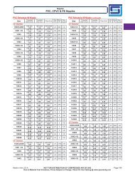
SDR 26 - Class 160<br />
Maximum W.P. 160 PSI* (all sizes)<br />
Nominal Pipe<br />
Size (in)<br />
O.D. Average I.D. Min. Wall Nominal Wt./Ft.<br />
1 1.315 1.175 0.060 0.173<br />
1-1/4 1.660 1.512 0.064 0.233<br />
1-1/2 1.900 1.734 0.073 0.300<br />
2 2.375 2.173 0.091 0.456<br />
2-1/2 2.875 2.635 0.110 0.657<br />
3 3.500 3.210 0.135 0.967<br />
4 4.500 4.134 0.173 1.570<br />
6 6.625 6.084 0.255 3.415<br />
8 8.625 7.921 0.332 5.786<br />
10 10.750 9.874 0.413 8.973<br />
12 12.750 11.711 0.490 12.623<br />
14 14.000 12.860 0.538 15.209<br />
16 16.000 14.696 0.615 19.881<br />
18 18.000 16.533 0.692 25.162<br />
20 20.000 18.370 0.769 31.064<br />
24 24.000 22.043 0.923 44.754<br />
SDR 41 - Class 100<br />
Maximum W.P. 100 PSI* (all sizes)<br />
Nominal Pipe<br />
Size (in)<br />
O.D. Average I.D. Min. Wall Nominal Wt./Ft.<br />
2-1/2 2.875 2.715 0.070 0.444<br />
3 3.500 3.310 0.085 0.643<br />
4 4.500 4.260 0.110 1.044<br />
6 6.625 6.281 0.162 2.205<br />
8 8.625 8.180 0.210 3.714<br />
10 10.750 10.195 0.262 5.774<br />
12 12.750 12.421 0.311 4.113<br />
14 14.000 13.270 0.341 9.888<br />
16 16.000 15.165 0.390 12.925<br />
18 18.000 17.061 0.439 16.352<br />
20 20.000 18.956 0.488 20.200<br />
24 24.000 22.748 0.585 29.070
Dimensions & Pressure Ratings<br />
SDR 32.5 - Class 125<br />
Maximum W.P. 125 PSI* (all sizes)<br />
Nom. Pipe<br />
Size (in)<br />
O.D. Average I.D. Min. Wall Nominal Wt./Ft.<br />
1/2 .840 .750 .045 .071<br />
3/4 1.050 0.950 0.050 0.099<br />
1 1.315 1.215 0.051 0.126<br />
1-1/4 1.660 1.520 0.060 0.221<br />
1-1/2 1.900 1.760 0.060 0.255<br />
2 2.375 2.209 0.073 0.378<br />
2-1/2 2.875 2.679 0.088 0.541<br />
3 3.500 3.264 0.108 0.793<br />
4 4.500 4.204 0.138 1.280<br />
SDR 32.5 - Class 125<br />
Maximum W.P. 125 PSI* (all sizes)<br />
Nom. Pipe<br />
Size (in)<br />
O.D. Average I.D. Min. Wall Nominal Wt./Ft.<br />
6 6.625 6.196 0.204 2.732<br />
8 8.625 8.063 0.265 4.658<br />
10 10.750 10.048 0.331 7.252<br />
12 12.750 11.919 0.392 10.182<br />
14 14.000 13.088 0.430 12.270<br />
16 16.000 14.957 0.492 16.037<br />
18 18.000 16.826 0.554 20.307<br />
20 20.000 18.696 0.615 25.063<br />
24 24.000 22.436 0.738 36.072<br />
Schedule 120 Schedule 120<br />
Nom. Pipe<br />
Average Minimum Nominal Maximum<br />
O.D.<br />
Size (in)<br />
I.D. Wall Wt./Ft. W.P. PSI*<br />
1/2 .840 .480 0.170 0.236 1010<br />
3/4 1.050 .690 0.170 0.311 770<br />
1 1.315 .891 0.200 0.464 720<br />
1-1/4 1.660 1.204 0.215 0.649 600<br />
1-1/2 1.900 1.423 0.225 0.787 540<br />
2 2.375 1.845 0.250 1.111 470<br />
Nom. Pipe<br />
Average Minimum Nominal Maximum<br />
O.D.<br />
Size (in)<br />
I.D. Wall Wt./Ft. W.P. PSI*<br />
2-1/2" 2.875 2.239 0.300 1.615 470<br />
3" 3.500 2.758 0.350 2.306 440<br />
4" 4.500 3.574 0.437 3.713 430<br />
6" 6.625 5.434 0.562 7.132 370<br />
8" 8.625 7.189 0.718 11.277 380<br />
Schedule 40<br />
Nominal Pipe<br />
Size (in)<br />
CPVC INDUSTRIAL PIPE<br />
Maximum<br />
W.P. PSI*<br />
O.D. Average I.D. Min. Wall<br />
Nominal<br />
Wt./ft.<br />
1/8 0.405 0.249 0.095 0.055 910<br />
1/4 0.540 0.344 0.119 0.093 780<br />
3/8 0.675 0.473 0.126 0.125 620<br />
1/2 0.840 0.602 0.147 0.184 600<br />
3/4 1.050 0.804 0.154 0.245 480<br />
1 1.315 1.029 0.179 0.360 450<br />
1-1/4 1.660 1.360 0.191 0.487 370<br />
1-1/2 1.900 1.590 0.200 0.581 330<br />
2 2.375 2.047 0.218 0.779 280<br />
2-1/2 2.875 2.445 0.276 1.229 300<br />
3 3.500 3.042 0.300 1.610 260<br />
4 4.500 3.998 0.337 2.292 220<br />
6 6.625 6.031 0.432 4.039 180<br />
8 8.625 7.942 0.500 6.079 160<br />
10 10.750 9.976 0.593 8.618 140<br />
12 12.750 11.889 0.687 11.397 130<br />
14 14.000 13.073 0.750 13.482 130<br />
16 16.000 14.940 0.843 17.619 130<br />
18 18.000 16.809 0.937 22.271 130<br />
20 20.000 18.743 1.031 26.162 120<br />
24 24.000 22.544 1.218 36.406 120<br />
Schedule 80<br />
Nominal Pipe<br />
Nominal Maximum<br />
Size (in)<br />
O.D. Average I.D. Min. Wall<br />
Wt./ft. W.P. PSI*<br />
1/8 0.405 0.195 0.095 0.068 1230<br />
1/4 0.540 0.282 0.119 0.115 1130<br />
3/8 0.675 0.403 0.126 0.158 920<br />
1/2 0.840 0.526 0.147 0.232 850<br />
3/4 1.050 0.722 0.154 0.314 690<br />
1 1.315 0.936 0.179 0.461 630<br />
1-1/4 1.660 1.255 0.191 0.638 520<br />
1-1/2 1.900 1.476 0.200 0.773 470<br />
2 2.375 1.913 0.218 1.070 400<br />
2-1/2 2.875 2.29 0.276 1.632 420<br />
3 3.500 2.864 0.300 2.186 370<br />
4 4.500 3.786 0.337 3.196 320<br />
6 6.625 5.709 0.432 6.102 280<br />
8 8.625 7.565 0.500 9.269 250<br />
10 10.750 9.493 0.593 13.744 230<br />
12 12.750 11.294 0.687 18.909 230<br />
14 14.000 12.41 0.750 22.681 220<br />
16 16.000 14.213 0.843 29.162 220<br />
18 18.000 16.014 0.937 36.487 220<br />
20 20.000 17.814 1.031 44.648 220<br />
24 24.000 21.418 1.218 63.341 210<br />
SDR 11 - Copper Tube Size (CTS)<br />
Maximum W.P. 400 PSI* (all sizes)<br />
Nominal<br />
Pipe Size<br />
Average<br />
O.D.<br />
Average<br />
I.D.<br />
Min.<br />
Wall<br />
Wall<br />
TOL<br />
Pressure Rating<br />
@ 73°F<br />
1/2 0.625 0.469 0.057 ±0.020 400<br />
3/4 0.87 0.695 0.080 ±0.020 400<br />
1 1.125 0.901 0.102 ±0.020 400<br />
1 1/4 1.375 1.105 0.125 ±0.020 400<br />
1 1/2 1.625 1.309 0.148 ±0.020 400<br />
2 2.125 1.716 0.193 ±0.023 400<br />
SDR13.5 - Class 315<br />
Maximum Working Pressure 315 psi (all sizes)<br />
Nominal Pipe<br />
Size (in)<br />
O.D. Average I.D. Min. Wall<br />
Nominal<br />
Wt./ft.<br />
3/4 1.050 0.874 0.078 0.182<br />
1 1.315 1.101 0.097 0.278<br />
1-1/4 1.660 1.394 0.123 0.436<br />
1-1/2 1.900 1.598 0.141 0.568<br />
2 2.375 2.003 0.176 0.875<br />
2-1/2 2.875 2.423 0.213 1.286<br />
3 3.500 2.950 0.259 1.906<br />
4 4.500 3.794 .333 3.146<br />
6 6.625 5.584 .491 6.828<br />
Note: *Pressure ratings are for water, non-shock, @73°F. Threaded pipe requires a 50% reduction in the pressure ratings stated for plain-end pipe @ 73°F. Threading<br />
recommended for Schedule 80 or heavier walls only. Maximum service temperature for PVC is 140°F. Maximum service temperature for CPVC is 200°F. <strong>The</strong> pressure rating<br />
of the pipe must be de-rated when working at elevated temperatures.<br />
Chemical resistance data should be referenced for proper material selection and possible de-rating when working with fl uids other than water.<br />
5
Dimensions & Pressure Ratings<br />
Temperature De-rating<br />
<strong>The</strong> pressure ratings given are for water, non-shock, @ 73°F.<br />
<strong>The</strong> specified derating factors for PVC or for CPVC are suitable<br />
for pipe conveying water at elevated temperatures. To<br />
determine elevated temperature rating, multiply 73°F [23°C]<br />
pressure rating by appropriate factor shown in the tables.<br />
When working near maximum specified temperature, solvent<br />
cement joints are recommended in place of threaded connections.<br />
Where disassembly is required at elevated temperatures<br />
use <strong>Spears</strong> ® Special reinforced (SR) adapters, flanges, unions<br />
or grooved coupling connections.<br />
Only Schedule 80 or heavier wall thickness pipe (PVC or<br />
CPVC) should be threaded. Do NOT thread Schedule 40<br />
pipe or other thinner-walled pipe such as SDR 13.5, SDR 21,<br />
SDR 26, etc. Threading requires a 50% reduction in the pipe’s<br />
specified pressure rating @ 73°F.<br />
See Chemical Resistance Data for Pressure Piping information<br />
for both chemical compatibility and potential temperature<br />
limitations when using certain chemicals.<br />
PVC Pipe<br />
Operating Temp (°F) De-Rating Factor<br />
73 1.00<br />
80 0.88<br />
90 0.75<br />
100 0.62<br />
110 0.51<br />
120 0.40<br />
130 0.31<br />
140 0.22<br />
EX: 2" PVC SCHEDULE 80 @ 120°F = 400 psi x 0.40 = 160 psi max. @ 120°F.<br />
CPVC Pipe<br />
Operating Temp (°F) De-Rating Factor<br />
73-80 1.00<br />
90 0.91<br />
100 0.82<br />
110 0.72<br />
120 0.65<br />
130 0.57<br />
140 0.50<br />
150 0.42<br />
160 0.40<br />
170 0.29<br />
180 0.25<br />
200 0.20<br />
EX: 2" CPVC SCHEDULE 80 @ 120°F = 400 psi x 0.65 = 260 psi max. @ 120°F<br />
6
Engineering & Design Data<br />
FLOW VELOCITY & FRICTION LOSS<br />
Friction Loss Through Pipe<br />
<strong>The</strong> Hazen-Williams equation below is widely used to calculate friction loss for water through PVC and CPVC pipe<br />
f = .2083 x (100) 1.852 x G 1.852<br />
C di 4.8655<br />
Where: f = friction head of feet of water per 100' for the specific pipe size and I.D.<br />
C = a constant for internal pipe roughness. 150 is the commonly accepted value for PVC and CPVC pipe.<br />
G = flow rate of gallons per minute (U.S. gallons).<br />
di = inside diameter of pipe in inches.<br />
Friction Loss Through Fittings<br />
Friction loss through fittings is expressed in equivalent feet of the same pipe size and schedule for the system flow rate.<br />
Schedule 40 head loss per 100' values are usually used for other wall thicknesses and standard iron pipe size O.D.’s.<br />
Average Friction Loss for PVC and CPVC Fittings in Equivalent Feet of Straight Run Pipe<br />
Item 1/2 3/4 1 1-1/4 1-1/2 2 2-1/2 3 4 6 8 10 12 14 16 18 20 24<br />
Tee Run 1.0 1.4 1.7 2.3 2.7 4.0 4.9 6.1 7.9 12.3 14.0 17.5 20.0 25.0 27.0 32.0 35.0 42.0<br />
Tee Branch 3.8 4.9 6.0 7.3 8.4 12.0 14.7 16.4 22.0 32.7 49.0 57.0 67.0 78.0 88.0 107.0 118.0 137.0<br />
90° Ell 1.5 2.0 2.5 3.8 4.0 5.7 6.9 7.9 11.4 16.7 21.0 26.0 32.0 37.0 43.0 53.0 58.0 67.0<br />
45° Ell .8 1.1 1.4 1.8 2.1 2.6 3.1 4.0 5.1 8.0 10.6 13.5 15.5 18.0 20.0 23.0 25.0 30.0<br />
Note: Values 10"-24": Approximate values from Nomograph.<br />
Pressure Drop In Valves & Strainers<br />
Pressure drop calculations can be made for valves and strainers<br />
for different fluids, flow rates, and sizes using the CV values and<br />
the following equation:<br />
Where:<br />
P = (G)2 (Sg)<br />
(C V ) 2<br />
P = Pressure drop in PSI; feet of water =<br />
PSI<br />
.4332<br />
G = Gallons per minute<br />
C V = Gallons per minute water per 1 PSI pressure drop<br />
Sg = Specific gravity of liquid (water = 1)<br />
C V<br />
Valves for Select <strong>Spears</strong> ® Valves and Strainers<br />
"<br />
Nominal Size 1/2 3/4 1 1-1/4 1-1/2 2 2-1/2 3 4 6 8 10 12<br />
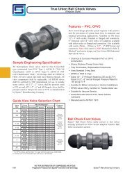
True Union 2000 Ball Valve 1 29 63 120 243 357 599 856 1416 2865 1952 -- -- --<br />
Single Entry Ball Valve 1 38 76 146 292 412 720 -- 1660 3104 -- -- -- --<br />
True Union 2000 Ball<br />
Check Valve<br />
6.3 17 25 65 86 130 200 275 500 800 -- -- --<br />
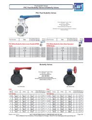
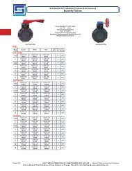
Butterfly Valve<br />
(90° - Full Open)<br />
-- -- -- -- 81 109 192 345 411 1125 2249 4440 6309<br />
Y-Check Valve 6.7 12.6 22.9 33.8 50.7 79.2 -- 235 387 -- -- -- --<br />
Y-Strainer (12 Mesh-Clean) 5.4 7.8 13.9 32.9 41.6 50.0 -- 74.6 169.0 -- -- -- --<br />
Basket Strainer (Clean) 4.5 10 15 30 46 72 110 172 270 630 750 893 1063<br />
1- Full Port Ball Valve Cv based on equivalent length of Schedule 80 pipe<br />
Water Velocities<br />
Velocities for water in feet per second at different GPM's and pipe inside diameters can be calculated as follows:<br />
V = .3208 G A<br />
Where:<br />
V = velocity in feet per second<br />
G = gallons per minute<br />
A = inside cross sectional area in square inches<br />
CAUTION: Flow velocities in excess of 5.0 feet per second are not recommended for closed-end systems. Contact <strong>Spears</strong> ® Technical<br />
Services for additional information.<br />
7
Engineering & Design Data<br />
Head Loss Characteristics of Water Flow Through Rigid Plastic Pipe – Nomograph<br />
<strong>The</strong> nomograph provides approximate values for water flow, head loss and water velocity for a wide range of plastic pipe sizes. Two known variables must be used to obtain<br />
the other variables by lining up the values on the scales using a ruler or straight edge. Flow velocities in excess of 5.0 feet per second are not recommended.<br />
<br />
<br />
<br />
<br />
<br />
<br />
<br />
<br />
<br />
<br />
<br />
<br />
<br />
<br />
<br />
<br />
<br />
<br />
<br />
<br />
<br />
<br />
<br />
<br />
<br />
<br />
<br />
<br />
<br />
<br />
<br />
<br />
<br />
<br />
<br />
<br />
<br />
<br />
<br />
<br />
<br />
<br />
<br />
<br />
<br />
<br />
<br />
<br />
<br />
<br />
<br />
<br />
<br />
<br />
<br />
<br />
<br />
<br />
<br />
<br />
<br />
<br />
<br />
<br />
<br />
<br />
<br />
<br />
<br />
<br />
<br />
<br />
<br />
<br />
<br />
<br />
<br />
<br />
<br />
<br />
<br />
<br />
<br />
<br />
<br />
<br />
<br />
<br />
<br />
<br />
<br />
<br />
<br />
<br />
<br />
<br />
<br />
<br />
<br />
<br />
<br />
<br />
<br />
<br />
<br />
<br />
<br />
<br />
<br />
<br />
<br />
<br />
<br />
<br />
<br />
<br />
<br />
<br />
<br />
<br />
<br />
<br />
<br />
<br />
<br />
<br />
<br />
<br />
<br />
<br />
<br />
<br />
<br />
<br />
<br />
<br />
<br />
<br />
<br />
<br />
<br />
<br />
<br />
<br />
<br />
<br />
<br />
<br />
<br />
<br />
<br />
<br />
<br />
<br />
<br />
<br />
<br />
<br />
<br />
<br />
<br />
<br />
<br />
<br />
<br />
<br />
<br />
<br />
<br />
<br />
<br />
<br />
<br />
<br />
<br />
8
Engineering & Design Data<br />
Flow<br />
Rate<br />
(Gallons/<br />
Minute)<br />
Flow<br />
Velocity<br />
(ft/sec.)<br />
Friction<br />
Loss (Ft.<br />
Water/<br />
100ft)<br />
Friction<br />
Loss (psi/<br />
100ft)<br />
Flow<br />
Velocity<br />
(ft/sec.)<br />
Friction<br />
Loss (Ft.<br />
Water/<br />
100ft)<br />
FLOW VELOCITY & FRICTION LOSS<br />
Friction<br />
Loss (psi/<br />
100ft)<br />
Flow<br />
Velocity<br />
(ft/sec.)<br />
Friction<br />
Loss (Ft.<br />
Water/<br />
100ft)<br />
Friction<br />
Loss (psi/<br />
100ft)<br />
SCHEDULE 40<br />
Flow<br />
Velocity<br />
(ft/sec.)<br />
Friction<br />
Loss (Ft.<br />
Water/<br />
100ft)<br />
GPM 1/8" 1/4" 3/8" 1/2" 3/4" 1" 1-1/4" GPM<br />
0.25 1.64 6.54 2.83 0.86 1.36 0.59 0.46 0.29 0.12 0.25<br />
0.50 3.27 23.60 10.23 1.72 4.90 2.12 0.91 1.04 0.45 0.50<br />
0.75 4.91 50.00 21.68 2.59 10.38 4.50 1.37 2.20 0.96 0.75<br />
1 6.55 85.18 36.93 3.45 17.68 7.66 1.82 3.75 1.63 1.13 1.16 0.50 0.63 0.28 0.12 0.39 0.09 0.04 0.22 0.02 0.01 1<br />
2 13.09 307.52 133.31 6.90 63.82 27.67 3.65 13.55 5.88 2.25 4.19 1.82 1.26 1.03 0.44 0.77 0.31 0.13 0.44 0.08 0.03 2<br />
5 17.25 348.29 150.98 9.11 73.96 32.06 5.63 22.88 9.92 3.16 5.60 2.43 1.93 1.69 0.73 1.10 0.43 0.19 5<br />
7 12.76 137.93 59.79 7.88 42.66 18.49 4.42 10.44 4.53 2.70 3.14 1.36 1.55 0.81 0.35 7<br />
10 11.26 82.59 35.80 6.31 20.21 8.76 3.86 6.08 2.64 2.21 1.57 0.68 10<br />
15 9.47 42.82 18.56 5.78 12.89 5.59 3.31 3.32 1.44 15<br />
20 12.63 72.95 31.63 7.71 21.96 9.52 4.42 5.65 2.45 20<br />
25 9.64 33.20 14.39 5.52 8.55 3.71 25<br />
30 11.57 46.54 20.17 6.62 11.98 5.19 30<br />
35 7.73 15.94 6.91 35<br />
40 8.83 20.41 8.85 40<br />
45 9.94 25.39 11.00 45<br />
50 11.04 30.86 13.38 50<br />
GPM 1-1/2" 2" 2-1/2" 3" 4" 5" 6" GPM<br />
2 0.32 0.04 0.02 2<br />
5 0.81 0.20 0.09 0.49 0.06 0.03 5<br />
7 1.13 0.38 0.16 0.68 0.11 0.05 0.48 0.05 0.02 7<br />
10 1.62 0.73 0.32 0.97 0.21 0.09 0.68 0.09 0.04 0.44 0.03 0.01 10<br />
15 2.42 1.55 0.67 1.46 0.45 0.20 1.02 0.19 0.08 0.66 0.07 0.03 15<br />
20 3.23 2.64 1.15 1.95 0.77 0.34 1.37 0.33 0.14 0.88 0.11 0.05 0.51 0.03 0.01 20<br />
25 4.04 4.00 1.73 2.44 1.17 0.51 1.71 0.49 0.21 1.10 0.17 0.07 0.64 0.05 0.02 25<br />
30 4.85 5.60 2.43 2.92 1.64 0.71 2.05 0.69 0.30 1.32 0.24 0.10 0.77 0.06 0.03 0.49 0.02 0.01 30<br />
35 5.65 7.45 3.23 3.41 2.18 0.94 2.39 0.92 0.40 1.54 0.32 0.14 0.89 0.08 0.04 0.57 0.03 0.01 35<br />
40 6.46 9.54 4.14 3.90 2.79 1.21 2.73 1.18 0.51 1.76 0.41 0.18 1.02 0.11 0.05 0.65 0.04 0.02 40<br />
45 7.27 11.87 5.15 4.39 3.47 1.51 3.07 1.46 0.63 1.99 0.51 0.22 1.15 0.13 0.06 0.73 0.04 0.02 45<br />
50 8.08 14.43 6.25 4.87 4.22 1.83 3.41 1.78 0.77 2.21 0.61 0.27 1.28 0.16 0.07 0.81 0.05 0.02 0.56 0.02 0.01 50<br />
60 9.69 20.22 8.77 5.85 5.92 2.56 4.10 2.49 1.08 2.65 0.86 0.37 1.53 0.23 0.10 0.97 0.08 0.03 0.67 0.03 0.01 60<br />
70 6.82 7.87 3.41 4.78 3.32 1.44 3.09 1.15 0.50 1.79 0.30 0.13 1.14 0.10 0.04 0.79 0.04 0.02 70<br />
75 7.31 8.94 3.88 5.12 3.77 1.63 3.31 1.30 0.56 1.92 0.34 0.15 1.22 0.11 0.05 0.84 0.05 0.02 75<br />
80 7.80 10.08 4.37 5.46 4.25 1.84 3.53 1.47 0.64 2.04 0.39 0.17 1.30 0.13 0.06 0.90 0.05 0.02 80<br />
90 8.77 12.53 5.43 6.15 5.28 2.29 3.97 1.82 0.79 2.30 0.48 0.21 1.46 0.16 0.07 1.01 0.07 0.03 90<br />
100 9.74 15.23 6.60 6.83 6.42 2.78 4.41 2.22 0.96 2.55 0.59 0.25 1.62 0.19 0.08 1.12 0.08 0.03 100<br />
125 12.18 23.03 9.98 8.54 9.70 4.21 5.52 3.35 1.45 3.19 0.89 0.38 2.03 0.29 0.13 1.40 0.12 0.05 125<br />
150 10.24 13.60 5.90 6.62 4.70 2.04 3.83 1.24 0.54 2.43 0.41 0.18 1.68 0.17 0.07 150<br />
175 7.72 6.25 2.71 4.47 1.65 0.72 2.84 0.55 0.24 1.96 0.22 0.10 175<br />
200 8.82 8.00 3.47 5.11 2.12 0.92 3.25 0.70 0.30 2.25 0.29 0.12 200<br />
250 11.03 12.10 5.24 6.39 3.20 1.39 4.06 1.06 0.46 2.81 0.43 0.19 250<br />
300 7.66 4.49 1.95 4.87 1.49 0.65 3.37 0.61 0.26 300<br />
350 8.94 5.97 2.59 5.68 1.98 0.86 3.93 0.81 0.35 350<br />
400 10.22 7.64 3.31 6.49 2.54 1.10 4.49 1.03 0.45 400<br />
450 7.30 3.15 1.37 5.05 1.29 0.56 450<br />
500 8.11 3.83 1.66 5.61 1.56 0.68 500<br />
Friction<br />
Loss (psi/<br />
100ft)<br />
Flow<br />
Velocity<br />
(ft/sec.)<br />
Friction<br />
Loss (Ft.<br />
Water/<br />
100ft)<br />
Friction<br />
Loss (psi/<br />
100ft)<br />
Flow<br />
Velocity<br />
(ft/sec.)<br />
Friction<br />
Loss (Ft.<br />
Water/<br />
100ft)<br />
Friction<br />
Loss (psi/<br />
100ft)<br />
Flow<br />
Velocity<br />
(ft/sec.)<br />
Friction<br />
Loss (Ft.<br />
Water/<br />
100ft)<br />
Friction<br />
Loss (psi/<br />
100ft)<br />
Flow<br />
Rate<br />
(Gallons/<br />
Minute)<br />
NOTE: <strong>Spears</strong> ® recommends that Flow Velocities be maintained at or below 5 feet per second in large diameter piping systems (i.e. 6" diameter and larger) to minimize the potential for<br />
hydraulic shock. Refer to <strong>Spears</strong> ® engineering section entitled "Hydraulic Shock" for additional information. Friction loss data based on utilizing mean wall dimensions to determine average<br />
ID; actual ID may vary.<br />
9
Engineering & Design Data<br />
Flow<br />
Rate<br />
(Gallons/<br />
Minute)<br />
Flow<br />
Velocity<br />
(ft/sec.)<br />
Friction<br />
Loss (Ft.<br />
Water/<br />
100ft)<br />
Friction<br />
Loss<br />
(psi/<br />
100ft)<br />
Flow<br />
Velocity<br />
(ft/sec.)<br />
Friction<br />
Loss (Ft.<br />
Water/<br />
100ft)<br />
Friction<br />
Loss<br />
(psi/<br />
100ft)<br />
FLOW VELOCITY & FRICTION LOSS<br />
Flow<br />
Velocity<br />
(ft/sec.)<br />
Friction<br />
Loss (Ft.<br />
Water/<br />
100ft)<br />
Friction<br />
Loss<br />
(psi/<br />
100ft)<br />
Flow<br />
Velocity<br />
(ft/sec.)<br />
SCHEDULE 40<br />
Friction<br />
Loss (Ft.<br />
Water/<br />
100ft)<br />
Friction<br />
Loss<br />
(psi/<br />
100ft)<br />
Flow<br />
Velocity<br />
(ft/sec.)<br />
GPM 8" 10" 12” 14” 16” 18” 20” 24” GPM<br />
100 0.65 0.02 0.01 100<br />
125 0.81 0.03 0.01 125<br />
150 0.97 0.04 0.02 150<br />
175 1.13 0.06 0.03 175<br />
200 1.29 0.08 0.03 0.82 0.02 0.01 200<br />
250 1.62 0.11 0.05 1.03 0.04 0.02 250<br />
300 1.94 0.16 0.07 1.23 0.05 0.02 300<br />
350 2.27 0.21 0.09 1.44 0.07 0.03 1.01 0.03 0.01 350<br />
400 2.59 0.27 0.12 1.64 0.09 0.04 1.16 0.04 0.02 0.96 0.02 0.01 0.73 0.01 0.01 400<br />
450 2.91 0.34 0.15 1.85 0.11 0.05 1.30 0.05 0.02 1.08 0.03 0.01 0.82 0.02 0.01 450<br />
500 3.24 0.41 0.18 2.05 0.14 0.06 1.44 0.06 0.02 1.19 0.04 0.02 0.91 0.02 0.01 500<br />
750 4.85 0.87 0.38 3.08 0.29 0.12 2.17 0.12 0.05 1.79 0.08 0.03 1.37 0.04 0.02 1.08 0.02 0.01 750<br />
1000 6.47 1.48 0.64 4.10 0.49 0.21 2.89 0.21 0.09 2.39 0.13 0.06 1.83 0.07 0.03 1.45 0.04 0.02 1.16 0.02 0.01 1000<br />
1250 5.13 0.74 0.32 3.61 0.31 0.14 2.99 0.20 0.09 2.29 0.10 0.04 1.81 0.06 0.03 1.45 0.03 0.01 1250<br />
1500 6.15 1.03 0.45 4.33 0.44 0.19 3.58 0.28 0.12 2.74 0.14 0.06 2.17 0.08 0.04 1.74 0.05 0.02 1.21 0.02 0.01 1500<br />
2000 5.78 0.75 0.33 4.78 0.47 0.20 3.66 0.25 0.11 2.89 0.14 0.06 2.32 0.08 0.04 1.61 0.03 0.01 2000<br />
2500 7.22 1.13 0.49 5.97 0.71 0.31 4.57 0.37 0.16 3.61 0.21 0.09 2.91 0.12 0.05 2.01 0.05 0.02 2500<br />
3000 7.17 1.00 0.43 5.49 0.52 0.23 4.34 0.29 0.13 3.49 0.17 0.08 2.41 0.07 0.03 3000<br />
3500 6.40 0.70 0.30 5.06 0.39 0.17 4.07 0.23 0.10 2.81 0.09 0.04 3500<br />
4000 5.78 0.50 0.22 4.65 0.30 0.13 3.21 0.12 0.05 4000<br />
4500 6.50 0.62 0.27 5.23 0.37 0.16 3.62 0.15 0.06 4500<br />
5000 5.81 0.45 0.19 4.02 0.18 0.08 5000<br />
5500 6.39 0.53 0.23 4.42 0.22 0.09 5500<br />
6000 6.97 0.63 0.27 4.82 0.25 0.11 6000<br />
7000 5.62 0.34 0.15 7000<br />
7500 6.03 0.39 0.17 7500<br />
8000 6.43 0.43 0.19 8000<br />
8500 6.83 0.49 0.21 8500<br />
Friction<br />
Loss (Ft.<br />
Water/<br />
100ft)<br />
Friction<br />
Loss<br />
(psi/<br />
100ft)<br />
Flow<br />
Velocity<br />
(ft/sec.)<br />
Friction<br />
Loss (Ft.<br />
Water/<br />
100ft)<br />
Friction<br />
Loss<br />
(psi/<br />
100ft)<br />
Flow<br />
Velocity<br />
(ft/sec.)<br />
Friction<br />
Loss (Ft.<br />
Water/<br />
100ft)<br />
Friction<br />
Loss<br />
(psi/<br />
100ft)<br />
Flow<br />
Velocity<br />
(ft/sec.)<br />
Friction<br />
Loss (Ft.<br />
Water/<br />
100ft)<br />
Friction<br />
Loss<br />
(psi/<br />
100ft)<br />
Flow<br />
Rate<br />
(Gallons/<br />
Minute)<br />
NOTE: <strong>Spears</strong> ® recommends that Flow Velocities be maintained at or below 5 feet per second in large diameter piping systems (i.e. 6" diameter and larger) to minimize the potential for<br />
hydraulic shock. Refer to <strong>Spears</strong> ® engineering section entitled "Hydraulic Shock" for additional information. Friction loss data based on utilizing mean wall dimensions to determine average<br />
ID; actual ID may vary.<br />
10
Engineering & Design Data<br />
Flow<br />
Rate<br />
(Gallons/<br />
Minute)<br />
Flow<br />
Velocity<br />
(ft/sec.)<br />
Friction<br />
Loss (Ft.<br />
Water/<br />
100ft)<br />
Friction<br />
Loss (psi/<br />
100ft)<br />
Flow<br />
Velocity<br />
(ft/sec.)<br />
Friction<br />
Loss (Ft.<br />
Water/<br />
100ft)<br />
FLOW VELOCITY & FRICTION LOSS<br />
Friction<br />
Loss (psi/<br />
100ft)<br />
Flow<br />
Velocity<br />
(ft/sec.)<br />
Friction<br />
Loss (Ft.<br />
Water/<br />
100ft)<br />
Friction<br />
Loss (psi/<br />
100ft)<br />
SCHEDULE 80<br />
Flow<br />
Velocity<br />
(ft/sec.)<br />
Friction<br />
Loss (Ft.<br />
Water/<br />
100ft)<br />
GPM 1/8" 1/4" 3/8" 1/2" 3/4" 1" 1-1/4" GPM<br />
0.25 2.67 21.47 9.31 1.29 3.57 1.55 0.63 0.63 0.27 0.25<br />
0.50 5.35 77.52 33.60 2.59 12.88 5.58 1.25 2.27 0.98 0.50<br />
0.75 8.02 164.25 71.20 3.88 27.29 11.83 1.88 4.80 2.08 0.75<br />
1 10.69 279.84 121.31 5.17 46.49 20.15 2.51 8.18 3.55 1.48 2.24 0.97 0.78 0.48 0.21 0.47 0.14 0.06 0.26 0.03 0.01 1<br />
2 21.39 1010.21 437.93 10.35 167.84 72.76 5.01 29.54 12.81 2.96 8.08 3.50 1.56 1.73 0.75 0.93 0.49 0.21 0.52 0.12 0.05 2<br />
5 25.87 915.95 397.07 12.53 161.23 69.89 7.39 44.12 19.12 3.91 9.45 4.10 2.33 2.67 1.16 1.30 0.64 0.28 5<br />
7 17.54 300.66 130.34 10.35 82.27 35.66 5.48 17.62 7.64 3.26 4.98 2.16 1.81 1.20 0.52 7<br />
10 14.78 159.26 69.04 7.82 34.11 14.79 4.66 9.65 4.18 2.59 2.32 1.00 10<br />
15 11.74 72.27 31.33 6.99 20.44 8.86 3.89 4.91 2.13 15<br />
20 15.65 123.13 53.38 9.33 34.82 15.09 5.18 8.36 3.62 20<br />
25 11.66 52.64 22.82 6.48 12.64 5.48 25<br />
30 13.99 73.78 31.98 7.77 17.71 7.68 30<br />
35 16.32 98.16 42.55 9.07 23.56 10.21 35<br />
40 18.65 125.70 54.49 10.37 30.17 13.08 40<br />
45 11.66 37.53 16.27 45<br />
50 12.96 45.62 19.77 50<br />
60 15.55 63.94 27.72 60<br />
70 18.14 85.06 36.87 70<br />
75 19.43 96.66 41.90 75<br />
80 20.73 108.93 47.22 80<br />
GPM 1-1/2" 2" 2-1/2" 3" 4" 5" 6" GPM<br />
1 0.19 0.01 0.01 0.11 0.00 0.00 0.08 0.00 0.00 0.05 0.00 0.00 1<br />
2 0.38 0.05 0.02 0.22 0.02 0.01 0.16 0.01 0.00 0.10 0.00 0.00 2<br />
5 0.96 0.29 0.13 0.56 0.08 0.04 0.39 0.03 0.01 0.25 0.01 0.01 5<br />
7 1.34 0.54 0.24 0.78 0.15 0.07 0.55 0.06 0.03 0.35 0.02 0.01 7<br />
10 1.92 1.05 0.46 1.12 0.30 0.13 0.78 0.12 0.05 0.50 0.04 0.02 10<br />
15 2.87 2.23 0.97 1.67 0.63 0.27 1.17 0.26 0.11 0.75 0.09 0.04 15<br />
20 3.83 3.80 1.65 2.23 1.07 0.47 1.56 0.45 0.19 1.00 0.15 0.07 0.57 0.04 0.02 20<br />
25 4.79 5.74 2.49 2.79 1.63 0.70 1.95 0.68 0.29 1.24 0.23 0.10 0.71 0.06 0.03 25<br />
30 5.75 8.04 3.49 3.35 2.28 0.99 2.34 0.95 0.41 1.49 0.32 0.14 0.85 0.08 0.04 0.54 0.03 0.01 30<br />
35 6.71 10.70 4.64 3.91 3.03 1.31 2.73 1.26 0.55 1.74 0.43 0.18 1.00 0.11 0.05 0.63 0.04 0.02 35<br />
40 7.66 13.71 5.94 4.46 3.88 1.68 3.11 1.62 0.70 1.99 0.54 0.24 1.14 0.14 0.06 0.72 0.05 0.02 40<br />
45 8.62 17.05 7.39 5.02 4.83 2.09 3.50 2.01 0.87 2.24 0.68 0.29 1.28 0.17 0.08 0.81 0.06 0.02 45<br />
50 9.58 20.72 8.98 5.58 5.87 2.54 3.89 2.45 1.06 2.49 0.82 0.36 1.42 0.21 0.09 0.90 0.07 0.03 0.63 0.03 0.01 50<br />
60 11.50 29.04 12.59 6.69 8.22 3.56 4.67 3.43 1.49 2.99 1.15 0.50 1.71 0.30 0.13 1.08 0.10 0.04 0.75 0.04 0.02 60<br />
70 13.41 38.64 16.75 7.81 10.94 4.74 5.45 4.56 1.98 3.48 1.54 0.67 1.99 0.39 0.17 1.26 0.13 0.06 0.88 0.05 0.02 70<br />
75 14.37 43.90 19.03 8.37 12.43 5.39 5.84 5.18 2.25 3.73 1.74 0.76 2.14 0.45 0.19 1.35 0.15 0.06 0.94 0.06 0.03 75<br />
80 15.33 49.48 21.45 8.93 14.01 6.07 6.23 5.84 2.53 3.98 1.97 0.85 2.28 0.51 0.22 1.44 0.16 0.07 1.00 0.07 0.03 80<br />
90 17.24 61.54 26.68 10.04 17.42 7.55 7.01 7.26 3.15 4.48 2.45 1.06 2.56 0.63 0.27 1.62 0.20 0.09 1.13 0.09 0.04 90<br />
100 19.16 74.80 32.42 11.16 21.18 9.18 7.79 8.83 3.83 4.98 2.97 1.29 2.85 0.76 0.33 1.80 0.25 0.11 1.25 0.10 0.04 100<br />
125 23.95 113.07 49.02 13.95 32.02 13.88 9.73 13.34 5.78 6.22 4.49 1.95 3.56 1.16 0.50 2.24 0.38 0.16 1.57 0.16 0.07 125<br />
150 28.74 158.49 68.71 16.74 44.88 19.45 11.68 18.70 8.11 7.47 6.30 2.73 4.27 1.62 0.70 2.69 0.53 0.23 1.88 0.22 0.10 150<br />
175 19.53 59.70 25.88 13.63 24.88 10.79 8.71 8.38 3.63 4.98 2.16 0.93 3.14 0.70 0.30 2.19 0.29 0.13 175<br />
200 22.32 76.45 33.14 15.57 31.86 13.81 9.96 10.73 4.65 5.70 2.76 1.20 3.59 0.90 0.39 2.51 0.37 0.16 200<br />
250 27.90 115.58 50.10 19.47 48.17 20.88 12.44 16.22 7.03 7.12 4.17 1.81 4.49 1.36 0.59 3.13 0.57 0.25 250<br />
300 23.36 67.52 29.27 14.93 22.74 9.86 8.55 5.85 2.54 5.39 1.90 0.83 3.76 0.79 0.34 300<br />
350 9.97 7.78 3.37 6.29 2.53 1.10 4.38 1.05 0.46 350<br />
400 11.39 9.96 4.32 7.18 3.24 1.41 5.01 1.35 0.59 400<br />
450 12.82 12.39 5.37 8.08 4.04 1.75 5.64 1.68 0.73 450<br />
500 8.98 4.90 2.13 6.26 2.04 0.89 500<br />
Friction<br />
Loss (psi/<br />
100ft)<br />
Flow<br />
Velocity<br />
(ft/sec.)<br />
Friction<br />
Loss (Ft.<br />
Water/<br />
100ft)<br />
Friction<br />
Loss (psi/<br />
100ft)<br />
Flow<br />
Velocity<br />
(ft/sec.)<br />
Friction<br />
Loss (Ft.<br />
Water/<br />
100ft)<br />
Friction<br />
Loss (psi/<br />
100ft)<br />
Flow<br />
Velocity<br />
(ft/sec.)<br />
Friction<br />
Loss (Ft.<br />
Water/<br />
100ft)<br />
Friction<br />
Loss (psi/<br />
100ft)<br />
Flow<br />
Rate<br />
(Gallons/<br />
Minute)<br />
NOTE: <strong>Spears</strong> ® recommends that Flow Velocities be maintained at or below 5 feet per second in large diameter piping systems (i.e. 6" diameter and larger) to minimize the potential for<br />
hydraulic shock. Refer to <strong>Spears</strong> ® engineering section entitled "Hydraulic Shock" for additional information. Friction loss data based on utilizing mean wall dimensions to determine average<br />
ID; actual ID may vary.<br />
11
Engineering & Design Data<br />
Flow<br />
Rate<br />
(Gallons/<br />
Minute)<br />
Flow<br />
Velocity<br />
(ft/sec.)<br />
Friction<br />
Loss (Ft.<br />
Water/<br />
100ft)<br />
Friction<br />
Loss<br />
(psi/<br />
100ft)<br />
Flow<br />
Velocity<br />
(ft/sec.)<br />
Friction<br />
Loss (Ft.<br />
Water/<br />
100ft)<br />
FLOW VELOCITY & FRICTION LOSS<br />
Friction<br />
Loss<br />
(psi/<br />
100ft)<br />
Flow<br />
Velocity<br />
(ft/sec.)<br />
Friction<br />
Loss (Ft.<br />
Water/<br />
100ft)<br />
Friction<br />
Loss<br />
(psi/<br />
100ft)<br />
Flow<br />
Velocity<br />
(ft/sec.)<br />
SCHEDULE 80<br />
Friction<br />
Loss (Ft.<br />
Water/<br />
100ft)<br />
Friction<br />
Loss<br />
(psi/<br />
100ft)<br />
Flow<br />
Velocity<br />
(ft/sec.)<br />
GPM 8" 10" 12" 14" 16" 18" 20” 24” GPM<br />
125 0.89 0.04 0.02 125<br />
150 1.07 0.06 0.02 150<br />
175 1.25 0.07 0.03 175<br />
200 1.43 0.10 0.04 0.91 0.03 0.01 200<br />
250 1.78 0.14 0.06 1.13 0.05 0.02 250<br />
300 2.14 0.20 0.09 1.36 0.07 0.03 300<br />
350 2.50 0.27 0.12 1.59 0.09 0.04 1.12 0.04 0.02 350<br />
400 2.85 0.34 0.15 1.81 0.11 0.05 1.28 0.05 0.02 1.06 0.03 0.01 0.81 0.02 0.01 400<br />
450 3.21 0.43 0.19 2.04 0.14 0.06 1.44 0.06 0.03 1.19 0.04 0.02 0.91 0.02 0.01 450<br />
500 3.57 0.52 0.23 2.27 0.17 0.07 1.60 0.07 0.03 1.33 0.05 0.02 1.01 0.02 0.01 500<br />
750 5.35 1.10 0.48 3.40 0.36 0.16 2.40 0.16 0.07 1.99 0.10 0.04 1.52 0.05 0.02 1.19 0.03 0.01 750<br />
1000 7.13 1.87 0.81 4.53 0.62 0.27 3.20 0.27 0.12 2.65 0.17 0.07 2.02 0.09 0.04 1.59 0.05 0.02 1.29 0.03 0.01 1000<br />
1250 5.66 0.94 0.41 4.00 0.40 0.17 3.31 0.25 0.11 2.53 0.13 0.06 1.99 0.07 0.03 1.61 0.04 0.02 1250<br />
1500 6.80 1.32 0.57 4.80 0.57 0.24 3.98 0.36 0.15 3.03 0.18 0.08 2.39 0.10 0.04 1.93 0.06 0.03 1.34 0.03 0.01 1500<br />
2000 6.40 0.96 0.42 5.30 0.61 0.26 4.04 0.31 0.14 3.18 0.18 0.08 2.57 0.10 0.05 1.78 0.04 0.02 2000<br />
2500 6.63 0.92 0.40 5.05 0.48 0.21 3.98 0.27 0.12 3.22 0.16 0.07 2.23 0.06 0.03 2500<br />
3000 7.95 1.29 0.56 6.06 0.67 0.29 4.78 0.37 0.16 3.86 0.22 0.10 2.67 0.09 0.04 3000<br />
3500 7.07 0.89 0.38 5.57 0.50 0.22 4.50 0.30 0.13 3.12 0.12 0.05 3500<br />
4000 6.37 0.64 0.28 5.15 0.38 0.16 3.56 0.15 0.07 4000<br />
4500 7.16 0.79 0.34 5.79 0.47 0.20 4.01 0.19 0.08 4500<br />
5000 6.43 0.57 0.25 4.45 0.23 0.10 5000<br />
5500 7.08 0.68 0.30 4.90 0.28 0.12 5500<br />
6000 7.72 0.80 0.35 5.34 0.33 0.14 6000<br />
7000 6.23 0.44 0.19 7000<br />
7500 6.68 0.49 0.21 7500<br />
8000 7.12 0.56 0.24 8000<br />
8500 7.57 0.62 0.27 8500<br />
Friction<br />
Loss (Ft.<br />
Water/<br />
100ft)<br />
Friction<br />
Loss<br />
(psi/<br />
100ft)<br />
Flow<br />
Velocity<br />
(ft/sec.)<br />
Friction<br />
Loss (Ft.<br />
Water/<br />
100ft)<br />
Friction<br />
Loss<br />
(psi/<br />
100ft)<br />
Flow<br />
Velocity<br />
(ft/sec.)<br />
Friction<br />
Loss (Ft.<br />
Water/<br />
100ft)<br />
Friction<br />
Loss<br />
(psi/<br />
100ft)<br />
Flow<br />
Velocity<br />
(ft/sec.)<br />
Friction<br />
Loss (Ft.<br />
Water/<br />
100ft)<br />
Friction<br />
Loss<br />
(psi/<br />
100ft)<br />
Flow<br />
Rate<br />
(Gallons/<br />
Minute)<br />
NOTE: <strong>Spears</strong> ® recommends that Flow Velocities be maintained at or below 5 feet per second in large diameter piping systems (i.e. 6" diameter and larger) to minimize the potential for<br />
hydraulic shock. Refer to <strong>Spears</strong> ® engineering section entitled "Hydraulic Shock" for additional information. Friction loss data based on utilizing mean wall dimensions to determine average<br />
ID; actual ID may vary.<br />
12
Engineering & Design Data<br />
Flow<br />
Rate<br />
(Gallons/<br />
Minute)<br />
Flow<br />
Velocity<br />
(ft/sec.)<br />
Friction<br />
Loss (Ft.<br />
Water/<br />
100ft)<br />
Friction<br />
Loss<br />
(psi/<br />
100ft)<br />
Flow<br />
Velocity<br />
(ft/sec.)<br />
Friction<br />
Loss (Ft.<br />
Water/<br />
100ft)<br />
FLOW VELOCITY & FRICTION LOSS<br />
Friction<br />
Loss<br />
(psi/<br />
100ft)<br />
Flow<br />
Velocity<br />
(ft/sec.)<br />
Friction<br />
Loss (Ft.<br />
Water/<br />
100ft)<br />
Friction<br />
Loss<br />
(psi/<br />
100ft)<br />
Flow<br />
Velocity<br />
(ft/sec.)<br />
SCHEDULE 120<br />
Friction<br />
Loss (Ft.<br />
Water/<br />
100ft)<br />
Friction<br />
Loss<br />
(psi/<br />
100ft)<br />
Flow<br />
Velocity<br />
(ft/sec.)<br />
GPM 1/2" 3/4" 1" 1-1/4" 1-1/2" 2" 2-1/2" 3" GPM<br />
1 1.77 3.50 1.52 0.86 0.60 0.26 0.51 0.17 0.07 0.28 0.04 0.02 0.20 0.02 0.01 0.12 0.00 0.00 0.08 0.00 0.00 0.05 0.00 0.00 1<br />
2 3.54 12.62 5.47 1.72 2.16 0.94 1.03 0.62 0.27 0.56 0.14 0.06 0.40 0.06 0.03 0.24 0.02 0.01 0.16 0.01 0.00 0.11 0.00 0.00 2<br />
5 8.86 68.86 29.85 4.29 11.78 5.11 2.57 3.40 1.47 1.41 0.78 0.34 1.01 0.35 0.15 0.60 0.10 0.04 0.41 0.04 0.02 0.27 0.01 0.01 5<br />
7 12.41 128.41 55.67 6.00 21.97 9.52 3.60 6.33 2.75 1.97 1.46 0.63 1.41 0.65 0.28 0.84 0.18 0.08 0.57 0.07 0.03 0.38 0.03 0.01 7<br />
10 17.72 248.59 107.76 8.58 42.53 18.43 5.15 12.26 5.31 2.82 2.83 1.23 2.02 1.26 0.54 1.20 0.36 0.15 0.82 0.14 0.06 0.54 0.05 0.02 10<br />
15 4" 12.87 90.11 39.06 7.72 25.98 11.26 4.23 6.00 2.60 3.03 2.66 1.15 1.80 0.75 0.33 1.22 0.29 0.13 0.81 0.11 0.05 15<br />
20 0.64 0.05 0.02 17.16 153.52 66.55 10.30 44.25 19.18 5.64 10.23 4.43 4.04 4.54 1.97 2.40 1.28 0.56 1.63 0.50 0.22 1.07 0.18 0.08 20<br />
25 0.80 0.08 0.03 12.87 66.90 29.00 7.05 15.46 6.70 5.04 6.86 2.97 3.00 1.94 0.84 2.04 0.76 0.33 1.34 0.27 0.12 25<br />
30 0.96 0.11 0.05 15.45 93.77 40.65 8.46 21.67 9.39 6.05 9.61 4.17 3.60 2.72 1.18 2.45 1.06 0.46 1.61 0.38 0.17 30<br />
35 1.12 0.14 0.06 18.02 124.75 54.08 9.87 28.83 12.50 7.06 12.79 5.54 4.20 3.61 1.57 2.85 1.41 0.61 1.88 0.51 0.22 35<br />
40 1.28 0.19 0.08 20.60 159.75 69.25 11.28 36.92 16.01 8.07 16.37 7.10 4.80 4.63 2.01 3.26 1.80 0.78 2.15 0.65 0.28 40<br />
45 1.44 0.23 0.10 5" 12.69 45.92 19.91 9.08 20.37 8.83 5.40 5.76 2.50 3.67 2.24 0.97 2.42 0.81 0.35 45<br />
50 1.60 0.28 0.12 0.69 0.04 0.02 14.09 55.82 24.20 10.09 24.75 10.73 6.00 7.00 3.03 4.08 2.73 1.18 2.69 0.99 0.43 50<br />
60 1.92 0.39 0.17 0.83 0.05 0.02 16.91 78.24 33.92 12.11 34.70 15.04 7.20 9.81 4.25 4.89 3.82 1.66 3.22 1.39 0.60 60<br />
70 2.24 0.52 0.23 0.97 0.07 0.03 19.73 104.09 45.12 14.12 46.16 20.01 8.40 13.05 5.66 5.71 5.09 2.21 3.76 1.84 0.80 70<br />
75 2.40 0.59 0.26 1.04 0.08 0.03 21.14 118.27 51.27 15.13 52.45 22.74 9.00 14.82 6.43 6.11 5.78 2.51 4.03 2.10 0.91 75<br />
80 2.56 0.67 0.29 1.11 0.09 0.04 22.55 133.29 57.78 16.14 59.11 25.62 9.60 16.71 7.24 6.52 6.51 2.82 4.30 2.36 1.02 80<br />
90 2.88 0.83 0.36 1.25 0.11 0.05 25.37 165.78 71.87 18.16 73.52 31.87 10.81 20.78 9.01 7.34 8.10 3.51 4.84 2.94 1.27 90<br />
100 3.20 1.01 0.44 1.38 0.13 0.06 6" 20.18 89.36 38.74 12.01 25.26 10.95 8.15 9.85 4.27 5.37 3.57 1.55 100<br />
125 4.00 1.53 0.66 1.73 0.20 0.09 0.99 0.05 0.02 25.22 135.09 58.56 15.01 38.18 16.55 10.19 14.89 6.45 6.72 5.40 2.34 125<br />
150 4.80 2.14 0.93 2.08 0.28 0.12 1.19 0.07 0.03 30.26 189.35 82.08 18.01 53.52 23.20 12.23 20.87 9.05 8.06 7.57 3.28 150<br />
175 5.60 2.85 1.24 2.42 0.37 0.16 1.38 0.10 0.04 21.01 71.20 30.86 14.27 27.76 12.04 9.40 10.07 4.36 175<br />
200 6.40 3.65 1.58 2.77 0.48 0.21 1.58 0.12 0.05 24.01 91.17 39.52 16.30 35.55 15.41 10.75 12.89 5.59 200<br />
250 8.00 5.52 2.39 3.46 0.72 0.31 1.98 0.18 0.08 30.01 137.83 59.75 20.38 53.75 23.30 13.43 19.49 8.45 250<br />
300 9.60 7.74 3.36 4.15 1.01 0.44 2.37 0.26 0.11 300<br />
350 11.20 10.30 4.46 4.84 1.34 0.58 2.77 0.34 0.15 350<br />
400 12.80 13.19 5.72 5.54 1.72 0.74 3.16 0.44 0.19 400<br />
450 14.40 16.40 7.11 6.23 2.14 0.93 3.56 0.55 0.24 450<br />
500 6.92 2.60 1.13 3.95 0.67 0.29 500<br />
750 10.38 5.50 2.38 5.93 1.14 0.61 750<br />
1,000 13.84 9.37 4.06 7.91 2.40 1.04 1,000<br />
1,250 9.88 3.63 1.57 1,250<br />
1,500 11.86 5.09 2.21 1,500<br />
2,000 15.81 8.67 3.76 2,000<br />
Friction<br />
Loss (Ft.<br />
Water/<br />
100ft)<br />
Friction<br />
Loss<br />
(psi/<br />
100ft)<br />
Flow<br />
Velocity<br />
(ft/sec.)<br />
Friction<br />
Loss (Ft.<br />
Water/<br />
100ft)<br />
Friction<br />
Loss<br />
(psi/<br />
100ft)<br />
Flow<br />
Velocity<br />
(ft/sec.)<br />
Friction<br />
Loss (Ft.<br />
Water/<br />
100ft)<br />
Friction<br />
Loss<br />
(psi/<br />
100ft)<br />
Flow<br />
Velocity<br />
(ft/sec.)<br />
Friction<br />
Loss (Ft.<br />
Water/<br />
100ft)<br />
Friction<br />
Loss<br />
(psi/<br />
100ft)<br />
Flow<br />
Rate<br />
(Gallons/<br />
Minute)<br />
NOTE: <strong>Spears</strong> ® recommends that Flow Velocities be maintained at or below 5 feet per second in large diameter piping systems (i.e. 6" diameter and larger) to minimize the potential for<br />
hydraulic shock. Refer to <strong>Spears</strong>® engineering section entitled "Hydraulic Shock" for additional information. Friction loss data based on utilizing mean wall dimensions to determine average<br />
ID; actual ID may vary.<br />
13
Engineering & Design Data<br />
FLOW VELOCITY & FRICTION LOSS<br />
SDR 11<br />
Flow<br />
Rate<br />
(Gallons/<br />
Minute)<br />
Velocity<br />
Feet<br />
Per<br />
Second<br />
Head Loss<br />
Feet of<br />
Water Per<br />
100 Ft.<br />
Pressure<br />
Loss PSI<br />
Per<br />
100 Ft.<br />
Velocity<br />
Feet<br />
Per<br />
Second<br />
Head Loss<br />
Feet of<br />
Water Per<br />
100 Ft.<br />
Pressure<br />
Loss PSI<br />
Per<br />
100 Ft.<br />
Velocity<br />
Feet<br />
Per<br />
Second<br />
Head Loss<br />
Feet of<br />
Water Per<br />
100 Ft.<br />
Pressure<br />
Loss PSI<br />
Per<br />
100 Ft.<br />
Velocity<br />
Feet<br />
Per<br />
Second<br />
Head Loss<br />
Feet of<br />
Water Per<br />
100 Ft.<br />
Pressure<br />
Loss PSI<br />
Per<br />
100 Ft.<br />
Velocity<br />
Feet<br />
Per<br />
Second<br />
Head Loss<br />
Feet of<br />
Water Per<br />
100 Ft.<br />
Pressure<br />
Loss PSI<br />
Per<br />
100 Ft.<br />
Velocity<br />
Feet<br />
Per<br />
Second<br />
Head Loss<br />
Feet of<br />
Water Per<br />
100 Ft.<br />
Pressure<br />
Loss PSI<br />
Per<br />
100 Ft.<br />
Flow<br />
Rate<br />
(Gallons/<br />
Minute)<br />
GPM 1⁄2" 3⁄4" 1" 1-1⁄4" 1-1⁄2" 2" GPM<br />
1 1.71 3.19 1.38 0.80 0.50 0.22 0.48 0.15 0.06 1<br />
2 3.42 11.53 5.00 1.60 1.82 0.79 0.96 0.53 0.23 2<br />
3 5.13 24.43 10.59 2.40 3.85 1.67 1.44 1.12 0.49 3<br />
4 6.83 41.62 18.04 3.20 6.55 2.84 1.93 1.91 0.83 4<br />
5 8.54 62.91 27.27 4.00 9.91 4.29 2.41 2.89 1.25 5<br />
6 10.25 88.18 38.23 4.79 13.89 6.02 2.89 4.05 1.76 6<br />
7 11.96 117.32 50.86 5.59 18.47 8.01 3.37 5.39 2.34 7<br />
8 13.67 150.23 65.13 6.39 23.66 10.26 3.85 6.90 2.99 8<br />
9 15.38 186.85 81.00 7.19 29.42 12.76 4.33 8.58 3.72 9<br />
10 17.08 227.11 98.45 7.99 35.76 15.50 4.82 10.43 4.52 3.23 3.94 1.71 2.31 1.75 0.76 1.35 0.49 0.21 10<br />
15 11.99 75.78 32.85 7.22 22.11 9.58 4.84 8.35 3.62 3.47 3.71 1.61 2.03 1.03 0.45 15<br />
20 15.98 129.11 55.97 9.63 37.67 16.33 6.46 14.23 6.17 4.63 6.33 2.74 2.70 1.76 0.76 20<br />
25 12.04 56.94 24.69 8.07 21.51 9.33 5.78 9.56 4.15 3.38 2.66 1.15 25<br />
30 14.45 79.82 34.60 9.68 30.15 13.07 6.94 13.40 5.81 4.05 3.73 1.62 30<br />
35 16.86 106.19 46.03 11.30 40.11 17.39 8.09 17.83 7.73 4.73 4.96 2.15 35<br />
40 12.91 51.37 22.27 9.25 22.83 9.90 5.40 6.35 2.75 40<br />
45 14.52 63.89 27.70 10.41 28.40 12.31 6.08 7.89 3.42 45<br />
50 16.14 77.66 33.66 11.56 34.52 14.96 6.75 9.60 4.16 50<br />
55 17.75 92.65 40.16 12.72 41.18 17.85 7.43 11.45 4.96 55<br />
60 13.88 48.38 20.97 8.10 13.45 5.83 60<br />
70 16.19 64.37 27.90 9.46 17.89 7.76 70<br />
80 10.61 22.91 9.93 80<br />
90 12.16 28.50 12.35 90<br />
100 13.51 34.64 15.02 100<br />
125 16.89 52.37 22.70 125<br />
NOTE: <strong>Spears</strong> ® recommends that Flow Velocities be maintained at or below 5 feet per second in large diameter piping systems (i.e. 6" diameter and larger) to minimize the potential for<br />
hydraulic shock. Refer to <strong>Spears</strong> ® engineering section entitled "Hydraulic Shock" for additional information. Friction loss data based on utilizing mean wall dimensions to determine average<br />
ID; actual ID may vary.<br />
14
Engineering & Design Data<br />
FLOW VELOCITY & FRICTION LOSS<br />
SDR 13.5<br />
Flow<br />
Rate cubic<br />
(Gallons/ ft/sec<br />
Minute)<br />
Velocity<br />
(ft/s)<br />
Friction<br />
Head<br />
Loss (ft<br />
water/<br />
100ft)<br />
Friction<br />
Pressure<br />
(psi/<br />
100ft)<br />
Velocity<br />
(ft/s)<br />
Friction<br />
Head<br />
Loss (ft<br />
water/<br />
100ft)<br />
Friction<br />
Pressure<br />
(psi/<br />
100ft)<br />
Velocity<br />
(ft/s)<br />
Friction<br />
Head<br />
Loss (ft<br />
water/<br />
100ft)<br />
Friction<br />
Pressure<br />
(psi/<br />
100ft)<br />
Velocity<br />
(ft/s)<br />
Friction<br />
Head<br />
Loss (ft<br />
water/<br />
100ft)<br />
Friction<br />
Pressure<br />
(psi/<br />
100ft)<br />
Velocity<br />
(ft/s)<br />
Friction<br />
Head<br />
Loss (ft<br />
water/<br />
100ft)<br />
Friction<br />
Pressure<br />
(psi/<br />
100ft)<br />
Velocity<br />
(ft/s)<br />
Friction<br />
Head<br />
Loss (ft<br />
water/<br />
100ft)<br />
Friction<br />
Pressure<br />
(psi/<br />
100ft)<br />
Velocity<br />
(ft/s)<br />
Friction<br />
Head<br />
Loss (ft<br />
water/<br />
100ft)<br />
Friction<br />
Pressure<br />
(psi/<br />
100ft)<br />
Velocity<br />
(ft/s)<br />
Friction<br />
Head<br />
Loss (ft<br />
water/<br />
100ft)<br />
Friction<br />
Pressure<br />
(psi/<br />
100ft)<br />
Flow<br />
Rate<br />
(Gallons/<br />
Minute)<br />
GPM 1/2" 3/4" 1" 1-1/4" 1-1/2" 2" 2-1/2" 3" GPM<br />
1 0.002 0.85 1.03 0.45 0.54 0.34 0.15 1<br />
2 0.004 1.69 2.05 0.89 1.07 0.68 0.29 0.68 0.40 0.17 0.42 0.13 0.06 0.32 0.065 0.028 0.20 0.03 0.013 2<br />
5 0.011 4.22 11.58 5.01 2.68 3.82 1.65 1.69 1.24 0.54 1.05 0.39 0.17 0.80 0.20 0.088 0.51 0.075 0.033 0.35 0.038 0.016 0.24 0.02 0.009 5<br />
7 0.016 5.91 21.24 9.20 3.75 7.01 3.03 2.36 2.28 0.99 1.47 0.72 0.31 1.12 0.37 0.16 0.72 0.125 0.054 0.49 0.53 0.023 0.33 0.03 0.012 7<br />
10 0.022 8.44 40.46 17.52 5.35 13.34 5.78 3.37 4.33 1.87 2.10 1.37 0.59 1.60 0.71 0.31 1.02 0.24 0.10 0.70 0.09 0.039 0.47 0.04 0.017 10<br />
15 0.033 4" 8.03 28.27 12.24 5.06 9.18 3.97 3.15 2.91 1.26 2.40 1.50 0.65 1.53 0.50 0.22 1.04 0.20 0.087 0.70 0.08 0.035 15<br />
20 0.045 0.57 0.04 0.017 10.70 48.17 20.86 6.74 15.64 6.77 4.21 4.96 2.91 3.20 2.55 1.10 2.04 0.85 0.37 1.39 0.34 0.15 0.94 0.13 0.056 20<br />
25 0.056 0.71 0.06 0.026 5" 8.43 23.65 10.24 5.26 7.49 3.24 4.00 3.85 1.67 2.55 1.29 0.56 1.74 0.51 0.22 1.17 0.19 0. 082 25<br />
30 0.067 0.85 0.08 0.035 0.56 0.03 0.013 10.11 33.15 14.35 6.31 10.50 4.55 4.80 5.40 2.34 3.05 1.80 0.78 2.09 0.71 0.31 1.41 0.27 0.12 30<br />
35 0.078 0.99 0.11 0.048 0.65 0.04 0.017 7.36 13.97 6.05 5.60 7.19 3.11 3.57 2.40 1.04 2.44 0.95 0.41 1.64 0.36 0.16 35<br />
40 0.089 1.14 0.14 0.060 0.74 0.05 0.022 8.41 17.90 7.75 6.40 9.20 3.98 4.08 3.07 1.33 2.78 1.21 0.52 1.88 0.46 0.20 40<br />
45 0.100 1.28 0.17 0.074 0.84 0.06 0.026 6" 9.46 22.26 9.64 7.20 11.44 4.95 4.59 3.82 1.65 3.13 1.51 0.65 2.11 0.58 0.25 45<br />
50 0.111 1.42 0.21 0.091 0.93 0.07 0.030 0.66 0.03 0.013 10.52 27.05 11.71 8.00 13.91 6.02 5.10 4.64 2.01 3.48 1.83 0.79 2.35 0.70 0.30 50<br />
60 0.134 1.70 0.29 0.13 1.12 0.10 0.043 0.79 0.04 0.017 9.60 19.50 8.44 6.12 6.50 2.81 4.18 2.57 1.11 2.82 0.98 0.42 60<br />
70 0.156 1.99 0.38 0.16 1.30 0.14 0.061 0.92 0.06 0.026 7.14 8.65 3.75 4.87 3.42 1.48 3.29 1.31 0.57 70<br />
75 0.167 2.13 0.44 0.19 1.40 0.16 0.069 0.98 0.07 0.030 7.65 9.83 4.26 5.22 3.88 1.68 3.52 1.49 0.65 75<br />
80 0.178 2.27 0.49 0.21 1.49 0.18 0.078 1.05 0.08 0.035 8.16 11.08 4.80 5.57 4.37 1.89 3.76 1.68 0.73 80<br />
90 0.201 2.56 0.61 0.26 1.67 0.22 0.095 1.18 0.09 0.039 9.18 13.78 5.97 6.27 5.44 2.36 4.23 2.09 0.90 90<br />
100 0.223 2.84 0.74 0.32 1.86 0.27 0.12 1.31 0.11 0.048 10.20 16.75 7.25 6.96 6.61 2.86 4.70 2.54 1.10 100<br />
125 0.279 3.55 1.13 0.49 2.33 0.40 0.18 1.64 0.17 0.074 8.70 10.01 4.33 5.88 3.84 1.66 125<br />
150 0.334 4.26 1.58 0.68 2.79 0.56 0.24 1.97 0.24 0.10 10.44 14.01 6.07 7.04 5.37 2.33 150<br />
175 0.390 4.97 2.10 0.91 3.26 0.75 0.33 2.30 0.32 0.14 8.22 7.15 3.10 175<br />
200 0.446 5.68 2.69 1.16 3.72 0.96 0.42 2.62 0.41 0.18 9.39 9.15 3.96 200<br />
250 0.557 7.10 4.07 1.76 4.66 1.46 0.63 3.28 0.62 0.27 11.74 13.86 6.00 250<br />
300 0.668 8.52 5.69 2.46 5.58 2.03 0.88 3.93 0.87 0.38 300<br />
350 0.780 9.94 7.58 3.29 6.52 2.70 1.17 4.59 1.16 0.50 350<br />
400 0.891 11.36 9.70 4.20 7.44 3.46 1.50 5.24 1.48 0.64 400<br />
450 1.003 8.37 4.31 1.87 5.90 1.84 0.80 450<br />
500 1.114 9.30 5.24 2.27 6.56 2.23 0.97 500<br />
750 9.83 4.73 2.05 750<br />
1000 2.228 13.11 8.06 3.49 1000<br />
NOTE: <strong>Spears</strong> ® recommends that Flow Velocities be maintained at or below 5 feet per second in large diameter piping systems (i.e. 6" diameter and larger) to minimize the potential for hydraulic<br />
shock. Refer to <strong>Spears</strong> ® engineering section entitled "Hydraulic Shock" for additional information. Friction loss data based on utilizing mean wall dimensions to determine average ID; actual<br />
ID may vary.<br />
15
Engineering & Design Data<br />
FLOW VELOCITY & FRICTION LOSS<br />
SDR 21<br />
Flow<br />
Rate<br />
(Gallons<br />
per<br />
Minute)<br />
Friction<br />
Flow<br />
Loss (Ft.<br />
Velocity<br />
Water/<br />
(ft/sec.)<br />
100ft)<br />
Friction<br />
Loss<br />
(psi/<br />
100ft)<br />
Flow<br />
Velocity<br />
(ft/sec.)<br />
Friction<br />
Loss (Ft.<br />
Water/<br />
100ft)<br />
Friction<br />
Loss<br />
(psi/<br />
100ft)<br />
Flow<br />
Velocity<br />
(ft/sec.)<br />
Friction<br />
Loss (Ft.<br />
Water/<br />
100ft)<br />
Friction<br />
Loss<br />
(psi/<br />
100ft)<br />
Flow<br />
Velocity<br />
(ft/sec.)<br />
Friction<br />
Loss (Ft.<br />
Water/<br />
100ft)<br />
Friction<br />
Loss<br />
(psi/<br />
100ft)<br />
Flow<br />
Velocity<br />
(ft/sec.)<br />
Friction<br />
Loss (Ft.<br />
Water/<br />
100ft)<br />
Friction<br />
Loss<br />
(psi/<br />
100ft)<br />
Flow<br />
Velocity<br />
(ft/sec.)<br />
Friction<br />
Loss (Ft.<br />
Water/<br />
100ft)<br />
Friction<br />
Loss<br />
(psi/<br />
100ft)<br />
Flow<br />
Velocity<br />
(ft/sec.)<br />
Friction<br />
Loss<br />
(Ft.<br />
Water/<br />
100ft)<br />
Friction<br />
Loss<br />
(psi/<br />
100ft)<br />
Flow<br />
Velocity<br />
(ft/sec.)<br />
Friction<br />
Loss (Ft.<br />
Water/<br />
100ft)<br />
Friction<br />
Loss<br />
(psi/<br />
100ft)<br />
Flow<br />
Rate<br />
(Gallons<br />
per<br />
Minute)<br />
GPM 1/2" 3/4" 1" 1-1/4" 1-1/2" 2" 2-1/2" 3" GPM<br />
1 0.49 0.16 0.07 0.30 0.05 0.02 0.19 0.01 0.01 0.14 0.01 0.00 0.09 0.00 0.00 0.06 0.00 0.00 0.04 0.00 0.00 1<br />
2 0.99 0.56 0.24 0.60 0.17 0.07 0.37 0.05 0.02 0.28 0.03 0.01 0.18 0.01 0.00 0.12 0.00 0.00 0.08 0.00 0.00 2<br />
5 2.46 3.06 1.33 1.49 0.91 0.39 0.93 0.29 0.12 0.71 0.15 0.06 0.45 0.05 0.02 0.31 0.02 0.01 0.21 0.01 0.00 5<br />
7 3.45 5.71 2.48 2.09 1.69 0.73 1.30 0.53 0.23 0.99 0.27 0.12 0.63 0.09 0.04 0.43 0.04 0.02 0.29 0.01 0.01 7<br />
10 4.93 11.06 4.80 2.99 3.27 1.42 1.86 1.03 0.45 1.41 0.53 0.23 0.90 0.18 0.08 0.61 0.07 0.03 0.41 0.03 0.01 10<br />
15 4" 7.39 23.44 10.16 4.48 6.93 3.00 2.79 2.18 0.95 2.12 1.12 0.49 1.35 0.37 0.16 0.92 0.15 0.06 0.62 0.06 0.02 15<br />
20 0.50 0.03 0.01 9.86 39.94 17.31 5.97 11.81 5.12 3.72 3.72 1.61 2.83 1.91 0.83 1.80 0.64 0.28 1.23 0.25 0.11 0.83 0.10 0.04 20<br />
25 0.62 0.04 0.02 5" 7.47 17.85 7.74 4.65 5.63 2.44 3.53 2.89 1.25 2.25 0.97 0.42 1.53 0.38 0.16 1.03 0.14 0.06 25<br />
30 0.75 0.06 0.03 0.49 0.02 0.01 8.96 25.02 10.85 5.58 7.89 3.42 4.24 4.05 1.75 2.70 1.35 0.59 1.84 0.53 0.23 1.24 0.20 0.09 30<br />
35 0.87 0.08 0.03 0.57 0.03 0.01 10.45 33.28 14.43 6.51 10.49 4.55 4.94 5.38 2.33 3.15 1.80 0.78 2.15 0.71 0.31 1.44 0.27 0.12 35<br />
40 1.00 0.10 0.04 0.65 0.04 0.02 7.43 13.44 5.83 5.65 6.89 2.99 3.60 2.31 1.00 2.45 0.90 0.39 1.65 0.34 0.15 40<br />
45 1.12 0.13 0.05 0.73 0.04 0.02 6" 8.36 16.71 7.25 6.36 8.57 3.72 4.05 2.87 1.24 2.76 1.12 0.49 1.86 0.43 0.19 45<br />
50 1.25 0.15 0.07 0.82 0.05 0.02 0.58 0.02 0.01 9.29 20.31 8.81 7.06 10.42 4.52 4.50 3.49 1.51 3.06 1.37 0.59 2.06 0.52 0.23 50<br />
60 1.50 0.21 0.09 0.98 0.08 0.03 0.69 0.03 0.01 8.48 14.60 6.33 5.41 4.89 2.12 3.68 1.91 0.83 2.48 0.73 0.32 60<br />
70 1.75 0.29 0.12 1.14 0.10 0.04 0.81 0.04 0.02 9.89 19.43 8.42 6.31 6.50 2.82 4.29 2.55 1.10 2.89 0.97 0.42 70<br />
75 1.87 0.32 0.14 1.22 0.12 0.05 0.86 0.05 0.02 10.59 22.08 9.57 6.76 7.39 3.20 4.60 2.89 1.25 3.09 1.10 0.48 75<br />
80 2.00 0.37 0.16 1.31 0.13 0.06 0.92 0.06 0.02 7.21 8.32 3.61 4.90 3.26 1.41 3.30 1.25 0.54 80<br />
90 2.24 0.46 0.20 1.47 0.16 0.07 1.04 0.07 0.03 8" 8.11 10.35 4.49 5.52 4.06 1.76 3.71 1.55 0.67 90<br />
100 2.49 0.55 0.24 1.63 0.20 0.09 1.15 0.08 0.04 0.68 0.02 0.01 9.01 12.58 5.46 6.13 4.93 2.14 4.13 1.88 0.82 100<br />
125 3.12 0.84 0.36 2.04 0.30 0.13 1.44 0.13 0.06 0.85 0.04 0.02 7.66 7.46 3.23 5.16 2.85 1.23 125<br />
150 3.74 1.17 0.51 2.45 0.42 0.18 1.73 0.18 0.08 1.02 0.05 0.02 9.19 10.45 4.53 6.19 3.99 1.73 150<br />
175 4.36 1.56 0.68 2.86 0.56 0.24 2.01 0.24 0.10 1.19 0.07 0.03 10.73 13.90 6.03 7.22 5.31 2.30 175<br />
200 4.99 2.00 0.87 3.26 0.71 0.31 2.30 0.30 0.13 1.36 0.08 0.04 8.25 6.80 2.95 200<br />
250 6.24 3.02 1.31 4.08 1.08 0.47 2.88 0.46 0.20 1.70 0.13 0.06 10.31 10.27 4.45 250<br />
300 7.48 4.23 1.84 4.90 1.51 0.65 3.45 0.65 0.28 2.04 0.18 0.08 300<br />
350 8.73 5.63 2.44 5.71 2.01 0.87 4.03 0.86 0.37 2.38 0.24 0.10 350<br />
400 9.98 7.21 3.13 6.53 2.57 1.12 4.61 1.10 0.48 2.71 0.30 0.13 400<br />
450 11.22 8.97 3.89 7.35 3.20 1.39 5.18 1.37 0.59 3.05 0.38 0.16 450<br />
500 8.16 3.89 1.69 5.76 1.66 0.72 3.39 0.46 0.20 500<br />
750 8.64 3.52 1.53 5.09 0.97 0.42 750<br />
1000 6.79 1.66 0.72 1000<br />
1250 8.48 2.51 1.09 1250<br />
NOTE: <strong>Spears</strong> ® recommends that Flow Velocities be maintained at or below 5 feet per second in large diameter piping systems (i.e. 6" diameter and larger) to minimize the potential for<br />
hydraulic shock. Refer to <strong>Spears</strong> ® engineering section entitled "Hydraulic Shock" for additional information. Friction loss data based on utilizing mean wall dimensions to determine average<br />
ID; actual ID may vary.<br />
16
Engineering & Design Data<br />
FLOW VELOCITY & FRICTION LOSS<br />
Flow<br />
Rate<br />
(Gallons<br />
per<br />
Minute)<br />
Flow<br />
Velocity<br />
(ft/sec.)<br />
Friction<br />
Loss (Ft.<br />
Water/<br />
100ft)<br />
Friction<br />
Loss<br />
(psi/<br />
100ft)<br />
Flow<br />
Velocity<br />
(ft/sec.)<br />
Friction<br />
Loss (Ft.<br />
Water/<br />
100ft)<br />
Friction<br />
Loss<br />
(psi/<br />
100ft)<br />
Flow<br />
Velocity<br />
(ft/sec.)<br />
Friction<br />
Loss (Ft.<br />
Water/<br />
100ft)<br />
Friction<br />
Loss<br />
(psi/<br />
100ft)<br />
Flow<br />
Velocity<br />
(ft/sec.)<br />
Friction<br />
Loss (Ft.<br />
Water/<br />
100ft)<br />
Friction<br />
Loss<br />
(psi/<br />
100ft)<br />
SDR 26<br />
Flow<br />
Velocity<br />
(ft/sec.)<br />
Friction<br />
Loss (Ft.<br />
Water/<br />
100ft)<br />
GPM 1" 1-1/4" 1-1/2" 2" 2-1/2" 3" 4" 5" 6" GPM<br />
1 0.30 0.04 0.02 0.18 0.01 0.01 0.14 0.01 0.00 0.09 0.00 0.00 0.06 0.00 0.00 0.04 0.00 0.00 1<br />
2 0.59 0.16 0.07 0.36 0.05 0.02 0.27 0.02 0.01 0.17 0.01 0.00 0.12 0.00 0.00 0.08 0.00 0.00 2<br />
5 1.48 0.88 0.38 0.89 0.26 0.11 0.68 0.13 0.06 0.43 0.04 0.02 0.29 0.02 0.01 0.20 0.01 0.00 5<br />
7 2.07 1.65 0.71 1.25 0.48 0.21 0.95 0.25 0.11 0.61 0.08 0.04 0.41 0.03 0.01 0.28 0.01 0.01 7<br />
10 2.96 3.19 1.38 1.79 0.94 0.41 1.36 0.48 0.21 0.86 0.16 0.07 0.59 0.06 0.03 0.40 0.02 0.01 10<br />
15 4.44 6.76 2.93 2.68 1.98 0.86 2.04 1.02 0.44 1.30 0.34 0.15 0.88 0.13 0.06 0.59 0.05 0.02 15<br />
20 5.91 11.52 4.99 3.57 3.38 1.46 2.72 1.73 0.75 1.73 0.58 0.25 1.18 0.23 0.10 0.79 0.09 0.04 0.48 0.03 0.01 20<br />
25 7.39 17.41 7.55 4.47 5.10 2.21 3.40 2.62 1.14 2.16 0.87 0.38 1.47 0.34 0.15 0.99 0.13 0.06 0.60 0.04 0.02 25<br />
30 8.87 24.40 10.58 5.36 7.15 3.10 4.07 3.67 1.59 2.59 1.23 0.53 1.76 0.48 0.21 1.19 0.18 0.08 0.72 0.05 0.02 0.47 0.02 0.01 30<br />
35 10.35 32.46 14.07 6.25 9.52 4.13 4.75 4.89 2.12 3.03 1.63 0.71 2.06 0.64 0.28 1.39 0.24 0.11 0.84 0.07 0.03 0.55 0.03 0.01 35<br />
40 11.83 41.57 18.02 7.14 12.19 5.28 5.43 6.26 2.71 3.46 2.09 0.90 2.35 0.82 0.35 1.58 0.31 0.14 0.96 0.09 0.04 0.63 0.03 0.01 40<br />
45 8.04 15.16 6.57 6.11 7.78 3.37 3.89 2.60 1.13 2.65 1.02 0.44 1.78 0.39 0.17 1.08 0.11 0.05 0.70 0.04 0.02 45<br />
50 8.93 18.43 7.99 6.79 9.46 4.10 4.32 3.16 1.37 2.94 1.24 0.54 1.98 0.47 0.20 1.19 0.14 0.06 0.78 0.05 0.02 0.55 0.02 0.01 50<br />
60 10.72 25.83 11.20 8.15 13.26 5.75 5.19 4.42 1.92 3.53 1.73 0.75 2.38 0.66 0.29 1.43 0.19 0.08 0.94 0.07 0.03 0.66 0.03 0.01 60<br />
70 9.51 17.64 7.65 6.05 5.88 2.55 4.12 2.30 1.00 2.77 0.88 0.38 1.67 0.26 0.11 1.10 0.09 0.04 0.77 0.04 0.02 70<br />
75 10.19 20.05 8.69 6.49 6.69 2.90 4.41 2.62 1.13 2.97 1.00 0.43 1.79 0.29 0.13 1.17 0.10 0.05 0.83 0.04 0.02 75<br />
80 10.87 22.59 9.79 6.92 7.54 3.27 4.70 2.95 1.28 3.17 1.13 0.49 1.91 0.33 0.14 1.25 0.12 0.05 0.88 0.05 0.02 80<br />
90 8" 12.22 28.10 12.18 7.78 9.37 4.06 5.29 3.67 1.59 3.57 1.40 0.61 2.15 0.41 0.18 1.41 0.15 0.06 0.99 0.06 0.03 90<br />
100 0.65 0.02 0.01 13.58 34.16 14.81 8.65 11.39 4.94 5.88 4.46 1.93 3.96 1.71 0.74 2.39 0.50 0.22 1.56 0.18 0.08 1.10 0.08 0.03 100<br />
125 0.81 0.03 0.01 10.81 17.22 7.47 7.35 6.74 2.92 4.95 2.58 1.12 2.99 0.75 0.33 1.96 0.27 0.12 1.38 0.11 0.05 125<br />
150 0.98 0.04 0.02 8.82 9.45 4.10 5.94 3.62 1.57 3.58 1.06 0.46 2.35 0.38 0.16 1.65 0.16 0.07 150<br />
175 1.14 0.06 0.03 10" 10.29 12.57 5.45 6.93 4.81 2.09 4.18 1.41 0.61 2.74 0.50 0.22 1.93 0.21 0.09 175<br />
200 1.30 0.08 0.03 0.84 0.03 0.01 7.92 6.16 2.67 4.78 1.80 0.78 3.13 0.64 0.28 2.21 0.27 0.12 200<br />
250 1.63 0.11 0.05 1.05 0.04 0.02 9.91 9.31 4.04 5.97 2.72 1.18 3.91 0.97 0.42 2.76 0.42 0.18 250<br />
300 1.95 0.16 0.07 1.26 0.06 0.02 12" 11.89 13.06 5.66 7.17 3.81 1.65 4.69 1.36 0.59 3.31 0.58 0.25 300<br />
350 2.28 0.21 0.09 1.47 0.07 0.03 1.04 0.03 0.01 14" 16" 8.36 5.07 2.20 5.48 1.81 0.79 3.86 0.77 0.34 350<br />
400 2.60 0.27 0.12 1.68 0.09 0.04 1.19 0.04 0.02 0.99 0.03 0.01 0.76 0.01 0.01 9.56 6.50 2.82 6.26 2.32 1.01 4.41 0.99 0.43 400<br />
450 2.93 0.34 0.15 1.88 0.12 0.05 1.34 0.05 0.02 1.11 0.03 0.01 0.85 0.02 0.01 10.75 8.08 3.50 7.04 2.89 1.25 4.96 1.23 0.53 450<br />
500 3.25 0.41 0.18 2.09 0.14 0.06 1.49 0.06 0.03 1.23 0.04 0.02 0.95 0.02 0.01 18" 7.82 3.51 1.52 5.52 1.50 0.65 500<br />
750 4.88 0.88 0.38 3.14 0.30 0.13 2.23 0.13 0.06 1.85 0.08 0.04 1.42 0.04 0.02 1.12 0.02 0.01 20" 8.27 3.17 1.38 750<br />
1000 6.51 1.50 0.65 4.19 0.51 0.22 2.98 0.22 0.10 2.47 0.14 0.06 1.89 0.07 0.03 1.49 0.04 0.02 1.21 0.03 0.01 11.03 5.41 2.34 1000<br />
1250 8.13 2.26 0.98 5.23 0.78 0.34 3.72 0.34 0.15 3.09 0.21 0.09 2.36 0.11 0.05 1.87 0.06 0.03 1.51 0.04 0.02 24" 1250<br />
1500 9.76 3.17 1.38 6.28 1.09 0.47 4.47 0.47 0.21 3.70 0.30 0.13 2.84 0.16 0.07 2.24 0.09 0.04 1.81 0.05 0.02 1.26 0.02 0.01 1500<br />
2000 8.38 1.85 0.80 5.95 0.81 0.35 4.94 0.51 0.22 3.78 0.27 0.12 2.99 0.15 0.07 2.42 0.09 0.04 1.68 0.04 0.02 2000<br />
2500 7.44 1.22 0.53 6.17 0.77 0.34 4.73 0.40 0.18 3.73 0.23 0.10 3.02 0.14 0.06 2.10 0.06 0.02 2500<br />
3000 7.41 1.08 0.47 5.67 0.57 0.25 4.48 0.32 0.14 3.63 0.19 0.08 2.52 0.08 0.03 3000<br />
3500 6.62 0.75 0.33 5.23 0.42 0.18 4.23 0.25 0.11 2.94 0.10 0.05 3500<br />
4000 5.97 0.54 0.24 4.84 0.33 0.14 3.36 0.13 0.06 4000<br />
4500 6.72 0.68 0.29 5.44 0.41 0.18 3.78 0.17 0.07 4500<br />
5000 6.05 0.49 0.21 4.20 0.20 0.09 5000<br />
5500 6.65 0.59 0.25 4.62 0.24 0.10 5500<br />
6000 7.26 0.69 0.30 5.04 0.28 0.12 6000<br />
7000 5.88 0.38 0.16 7000<br />
7500 6.30 0.43 0.19 7500<br />
8000 6.72 0.48 0.21 8000<br />
8500 7.14 0.54 0.24 8500<br />
Friction<br />
Loss<br />
(psi/<br />
100ft)<br />
Flow<br />
Velocity<br />
(ft/sec.)<br />
Friction<br />
Loss (Ft.<br />
Water/<br />
100ft)<br />
Friction<br />
Loss<br />
(psi/<br />
100ft)<br />
Flow<br />
Velocity<br />
(ft/sec.)<br />
Friction<br />
Loss (Ft.<br />
Water/<br />
100ft)<br />
Friction<br />
Loss<br />
(psi/<br />
100ft)<br />
Flow<br />
Velocity<br />
(ft/sec.)<br />
Friction<br />
Loss (Ft.<br />
Water/<br />
100ft)<br />
Friction<br />
Loss<br />
(psi/<br />
100ft)<br />
Flow<br />
Velocity<br />
(ft/sec.)<br />
Friction<br />
Loss (Ft.<br />
Water/<br />
100ft)<br />
Friction<br />
Loss<br />
(psi/<br />
100ft)<br />
Flow<br />
Rate<br />
(Gallons<br />
per<br />
Minute)<br />
NOTE: <strong>Spears</strong> ® recommends that Flow Velocities be maintained at or below 5 feet per second in large diameter piping systems (i.e. 6" diameter and larger) to minimize the potential for<br />
hydraulic shock. Refer to <strong>Spears</strong> ® engineering section entitled "Hydraulic Shock" for additional information. Friction loss data based on utilizing mean wall dimensions to determine average<br />
ID; actual ID may vary.<br />
17
Engineering & Design Data<br />
Flow Rate<br />
(Gallons<br />
per<br />
Minute)<br />
18<br />
Flow<br />
Velocity (ft/<br />
sec.)<br />
Friction<br />
Loss (Ft.<br />
Water/<br />
100ft)<br />
Friction<br />
Loss (psi/<br />
100ft)<br />
Flow<br />
Velocity (ft/<br />
sec.)<br />
Friction<br />
Loss (Ft.<br />
Water/<br />
100ft)<br />
FLOW VELOCITY & FRICTION LOSS<br />
SDR 32.5<br />
Friction<br />
Loss (psi/<br />
100ft)<br />
Flow<br />
Velocity (ft/<br />
sec.)<br />
Friction<br />
Loss (Ft.<br />
Water/<br />
100ft)<br />
Friction<br />
Loss (psi/<br />
100ft)<br />
Flow<br />
Velocity (ft/<br />
sec.)<br />
Friction<br />
Loss (Ft.<br />
Water/<br />
100ft)<br />
GPM 6" 8" 10" 12" 14" 16" 18" GPM<br />
20 0.21 0.00 0.00 0.13 0.00 0.00 0.08 0.00 0.00 0.06 0.00 0.00 0.05 0.00 0.00 0.04 0.00 0.00 0.03 0.00 0.00 20<br />
40 0.43 0.02 0.01 0.25 0.00 0.00 0.16 0.00 0.00 0.11 0.00 0.00 0.10 0.00 0.00 0.07 0.00 0.00 0.06 0.00 0.00 40<br />
60 0.64 0.02 0.01 0.38 0.00 0.00 0.24 0.00 0.00 0.17 0.00 0.00 0.14 0.00 0.00 0.11 0.00 0.00 0.09 0.00 0.00 60<br />
80 0.85 0.05 0.02 0.50 0.02 0.01 0.32 0.00 0.00 0.23 0.00 0.00 0.19 0.00 0.00 0.15 0.00 0.00 0.12 0.00 0.00 80<br />
100 1.06 0.07 0.03 0.63 0.02 0.01 0.40 0.00 0.00 0.29 0.00 0.00 0.24 0.00 0.00 0.18 0.00 0.00 0.14 0.00 0.00 100<br />
150 1.60 0.14 0.06 0.94 0.05 0.02 0.61 0.02 0.01 0.43 0.00 0.00 0.36 0.00 0.00 0.27 0.00 0.00 0.22 0.00 0.00 150<br />
200 2.13 0.25 0.11 1.26 0.07 0.03 0.81 0.02 0.01 0.57 0.00 0.00 0.48 0.00 0.00 0.36 0.00 0.00 0.29 0.00 0.00 200<br />
250 2.66 0.37 0.16 1.57 0.12 0.05 1.01 0.05 0.02 0.72 0.02 0.01 0.60 0.00 0.00 0.46 0.00 0.00 0.36 0.00 0.00 250<br />
300 3.19 0.53 0.23 1.88 0.14 0.06 1.21 0.05 0.02 0.86 0.02 0.01 0.71 0.02 0.01 0.55 0.00 0.00 0.43 0.00 0.00 300<br />
350 3.72 0.72 0.31 2.20 0.21 0.09 1.41 0.07 0.03 1.01 0.02 0.01 0.83 0.02 0.01 0.64 0.00 0.00 0.50 0.00 0.00 350<br />
400 4.26 0.90 0.39 2.51 0.25 0.11 1.62 0.09 0.04 1.15 0.05 0.02 0.95 0.02 0.01 0.73 0.02 0.01 0.58 0.00 0.00 400<br />
450 4.79 1.13 0.49 2.82 0.32 0.14 1.82 0.12 0.05 1.29 0.05 0.02 1.07 0.02 0.01 0.82 0.02 0.01 0.65 0.00 0.00 450<br />
500 5.32 1.36 0.59 3.14 0.37 0.16 2.02 0.14 0.06 1.44 0.05 0.02 1.19 0.05 0.02 0.91 0.02 0.01 0.72 0.00 0.00 500<br />
550 5.85 1.64 0.71 3.45 0.46 0.20 2.22 0.16 0.07 1.58 0.07 0.03 1.31 0.05 0.02 1.00 0.02 0.01 0.79 0.02 0.01 550<br />
600 6.38 1.91 0.83 3.77 0.53 0.23 2.42 0.18 0.08 1.72 0.07 0.03 1.43 0.05 0.02 1.09 0.02 0.01 0.86 0.02 0.01 600<br />
650 6.91 2.24 0.97 4.08 0.62 0.27 2.63 0.21 0.09 1.87 0.09 0.04 1.55 0.07 0.03 1.19 0.02 0.01 0.94 0.02 0.01 650<br />
700 7.45 2.56 1.11 4.39 0.72 0.31 2.83 0.25 0.11 2.01 0.12 0.05 1.67 0.07 0.03 1.28 0.05 0.02 1.01 0.02 0.01 700<br />
750 7.98 2.91 1.26 4.71 0.81 0.35 3.03 0.28 0.12 2.15 0.12 0.05 1.79 0.07 0.03 1.37 0.05 0.02 1.08 0.02 0.01 750<br />
800 8.51 3.28 1.42 5.02 0.90 0.39 3.23 0.30 0.13 2.30 0.14 0.06 1.91 0.09 0.04 1.46 0.05 0.02 1.15 0.02 0.01 800<br />
850 9.04 3.67 1.59 5.33 1.01 0.44 3.43 0.35 0.15 2.44 0.16 0.07 2.02 0.09 0.04 1.55 0.05 0.02 1.22 0.02 0.01 850<br />
900 5.65 1.13 0.49 3.64 0.39 0.17 2.59 0.16 0.07 2.14 0.12 0.05 1.64 0.05 0.02 1.30 0.02 0.01 900<br />
950 5.96 1.25 0.54 3.84 0.44 0.19 2.73 0.18 0.08 2.26 0.12 0.05 1.73 0.07 0.03 1.37 0.05 0.02 950<br />
1000 6.28 1.36 0.59 4.04 0.46 0.20 2.87 0.21 0.09 2.38 0.14 0.06 1.82 0.07 0.03 1.44 0.05 0.02 1000<br />
1050 6.59 1.50 0.65 4.24 0.51 0.22 3.02 0.23 0.10 2.50 0.14 0.06 1.92 0.07 0.03 `1.51 0.05 0.02 1050<br />
1100 6.90 1.64 0.71 4.45 0.55 0.24 3.16 0.25 0.11 2.62 0.16 0.07 2.01 0.09 0.04 1.59 0.05 0.02 1100<br />
1150 4.65 0.60 0.26 3.30 0.25 0.11 2.74 0.16 0.07 2.10 0.09 0.04 1.66 0.05 0.02 1150<br />
1200 4.85 0.67 0.29 3.45 0.28 0.12 2.86 0.18 0.08 2.19 0.09 0.04 1.73 0.05 0.02 1200<br />
1250 5.05 0.72 0.31 3.59 0.30 0.13 2.98 0.21 0.09 2.28 0.09 0.04 1.80 0.07 0.03 1250<br />
1300 5.25 0.76 0.33 3.73 0.32 0.14 3.10 0.21 0.09 2.37 0.12 0.05 1.87 0.07 0.03 1300<br />
1350 5.46 0.83 0.36 3.88 0.35 0.15 3.22 0.23 0.10 2.46 0.12 0.05 1.95 0.07 0.03 1350<br />
1400 5.66 0.88 0.38 4.02 0.39 0.17 3.33 0.23 0.10 2.55 0.12 0.05 2.02 0.07 0.03 1400<br />
1450 5.86 0.95 0.41 4.17 0.42 0.18 3.45 0.25 0.11 2.64 0.14 0.06 2.09 0.07 0.03 1450<br />
1500 6.06 0.99 0.43 4.31 0.44 0.19 3.57 0.28 0.12 2.74 0.14 0.06 2.16 0.09 0.04 1500<br />
1600 6.47 1.13 0.49 4.60 0.48 0.21 3.81 0.30 0.13 2.92 0.16 0.07 2.31 0.09 0.04 1600<br />
1700 6.87 1.25 0.54 4.88 0.55 0.24 4.05 0.35 0.15 3.10 0.18 0.08 2.45 0.09 0.04 1700<br />
1800 5.17 0.60 0.26 4.29 0.39 0.17 3.28 0.21 0.09 2.59 0.12 0.05 1800<br />
1900 5.46 0.67 0.29 4.53 0.42 0.18 3.47 0.23 0.10 2.74 0.12 0.05 1900<br />
2000 5.74 0.74 0.32 4.76 0.46 0.20 3.65 0.25 0.11 2.88 0.14 0.06 2000<br />
2100 6.03 0.81 0.35 5.00 0.51 0.22 3.83 0.28 0.12 3.03 0.16 0.07 2100<br />
2200 6.32 0.88 0.38 5.24 0.55 0.24 4.01 0.30 0.13 3.17 0.16 0.07 2200<br />
2300 6.61 0.97 0.42 5.48 0.60 0.26 4.20 0.32 0.14 3.31 0.18 0.08 2300<br />
2400 6.89 1.04 0.45 5.72 0.65 0.28 4.38 0.35 0.15 3.46 0.18 0.08 2400<br />
2500 7.18 1.11 0.48 5.95 0.72 0.31 4.56 0.37 0.16 3.60 0.21 0.09 2500<br />
2600 7.47 1.20 0.52 6.19 0.76 0.33 4.74 0.39 0.17 3.75 0.23 0.10 2600<br />
2700 7.76 1.29 0.56 6.43 0.81 0.35 4.92 0.44 0.19 3.89 0.23 0.10 2700<br />
2800 8.04 1.38 0.60 6.67 0.88 0.38 5.11 0.46 0.20 4.04 0.25 0.11 2800<br />
2900 8.33 1.48 0.64 6.91 0.92 0.40 5.29 0.48 0.21 4.18 0.28 0.12 2900<br />
3000 8.62 1.57 0.68 7.15 0.99 0.43 5.47 0.51 0.22 4.32 0.30 0.13 3000<br />
3100 8.90 1.66 0.72 7.38 1.06 0.46 5.65 0.55 0.24 4.47 0.30 0.13 3100<br />
3200 9.19 1.78 0.77 7.62 1.13 0.49 5.84 0.58 0.25 4.61 0.32 0.14 3200<br />
3300 7.86 1.18 0.51 6.02 0.62 0.27 4.76 0.35 0.15 3300<br />
3400 8.10 1.25 0.54 6.20 0.65 0.28 4.90 0.37 0.16 3400<br />
3500 8.34 1.31 0.57 6.38 0.69 0.30 5.04 0.39 0.17 3500<br />
3600 8.57 1.38 0.60 6.57 0.74 0.32 5.19 0.42 0.18 3600<br />
3700 8.81 1.45 0.63 6.75 0.76 0.33 5.33 0.44 0.19 3700<br />
3800 6.93 0.81 0.35 5.48 0.46 0.20 3800<br />
3900 7.11 0.85 0.37 5.62 0.48 0.21 3900<br />
4000 7.30 0.88 0.38 5.76 0.51 0.22 4000<br />
4100 7.48 0.92 0.40 5.91 0.53 0.23 4100<br />
4200 7.66 0.97 0.42 6.05 0.55 0.24 4200<br />
4300 6.20 0.58 0.25 4300<br />
4400 6.34 0.60 0.26 4400<br />
4500 6.49 0.62 0.27 4500<br />
4600 6.63 0.65 0.28 4600<br />
4700 6.77 0.67 0.29 4700<br />
NOTE: <strong>Spears</strong> ® recommends that Flow Velocities be maintained at or below 5 feet per second in large diameter piping systems (i.e. 6" diameter and larger) to minimize the potential for<br />
hydraulic shock. Refer to <strong>Spears</strong> ® engineering section entitled "Hydraulic Shock" for additional information. Friction loss data based on utilizing mean wall dimensions to determine average<br />
ID; actual ID may vary.<br />
Friction<br />
Loss (psi/<br />
100ft)<br />
Flow<br />
Velocity (ft/<br />
sec.)<br />
Friction<br />
Loss (Ft.<br />
Water/<br />
100ft)<br />
Friction<br />
Loss (psi/<br />
100ft)<br />
Flow<br />
Velocity (ft/<br />
sec.)<br />
Friction<br />
Loss (Ft.<br />
Water/<br />
100ft)<br />
Friction<br />
Loss (psi/<br />
100ft)<br />
Flow<br />
Velocity (ft/<br />
sec.)<br />
Friction<br />
Loss (Ft.<br />
Water/<br />
100ft)<br />
Friction<br />
Loss (psi/<br />
100ft)<br />
Flow Rate<br />
(Gallons<br />
per<br />
Minute)
Engineering & Design Data<br />
FLOW VELOCITY & FRICTION LOSS<br />
SDR 41<br />
Flow Rate<br />
(Gallons per<br />
Minute)<br />
Flow<br />
Velocity (ft/<br />
sec.)<br />
Friction<br />
Loss (Ft.<br />
Water/<br />
100ft)<br />
Friction<br />
Loss<br />
(psi/ 100ft)<br />
Flow<br />
Velocity (ft/<br />
sec.)<br />
Friction<br />
Loss (Ft.<br />
Water/<br />
100ft)<br />
Friction<br />
Loss<br />
(psi/ 100ft)<br />
Flow<br />
Velocity (ft/<br />
sec.)<br />
Friction<br />
Loss (Ft.<br />
Water/<br />
100ft)<br />
Friction<br />
Loss<br />
(psi/ 100ft)<br />
Flow Rate<br />
(Gallons per<br />
Minute)<br />
GPM 18" GPM<br />
750 1.05 0.02 0.01 750<br />
1000 1.40 0.04 0.02 20" 1000<br />
1250 1.75 0.05 0.02 1.42 0.03 0.01 24" 1250<br />
1500 2.10 0.08 0.03 1.70 0.05 0.02 1.18 0.02 0.01 1500<br />
2000 2.81 0.13 0.06 2.27 0.08 0.03 1.58 0.03 0.01 2000<br />
2500 3.51 0.20 0.08 2.84 0.12 0.05 1.97 0.05 0.02 2500<br />
3000 4.21 0.27 0.12 3.41 0.16 0.07 2.37 0.07 0.03 3000<br />
3500 4.91 0.36 0.16 3.98 0.22 0.09 2.76 0.09 0.04 3500<br />
4000 5.61 0.47 0.20 4.55 0.28 0.12 3.16 0.12 0.05 4000<br />
4500 6.31 0.58 0.25 5.11 0.35 0.15 3.55 0.14 0.06 4500<br />
5000 5.68 0.42 0.18 3.95 0.17 0.08 5000<br />
5500 6.25 0.50 0.22 4.34 0.21 0.09 5500<br />
6000 6.82 0.59 0.26 4.73 0.24 0.11 6000<br />
7000 5.52 0.32 0.14 7000<br />
7500 5.92 0.37 0.16 7500<br />
8000 6.31 0.42 0.18 8000<br />
8500 6.71 0.47 0.20 8500<br />
NOTE: <strong>Spears</strong> ® recommends that Flow Velocities be maintained at or below 5 feet per second in large diameter piping systems (i.e. 6" diameter and larger) to minimize the potential for<br />
hydraulic shock. Refer to <strong>Spears</strong> ® engineering section entitled "Hydraulic Shock" for additional information. Friction loss data based on utilizing mean wall dimensions to determine average<br />
ID; actual ID may vary.<br />
19
Engineering & Design Data<br />
Hydraulic Shock<br />
Hydraulic shock is the rapid increase in pressure due to a shock wave produced by a sudden change in system fluid velocity. <strong>If</strong><br />
uncontrolled or insufficient pressure rated piping is used, these pressure surges can easily burst pipe and break valves or fittings.<br />
<strong>The</strong> term “water hammer” commonly used is derived from the sounds produced, but it is the hydraulic shock vibrations that can be<br />
damaging to piping systems. This is typically the result of sudden starting or stopping of a flowing column of liquid, such as water.<br />
Energy from the momentum of water in motion is converted to pressure when the flow is abruptly halted. A shock wave is produced<br />
that travels through the piping until it is stopped and bounces back to the original obstruction. This instantaneous shock to the system<br />
can lead to excessively high pressures. Hydraulic shock is frequently produced by rapid valve opening and closing, pumps starting<br />
and stopping, or even from a high speed wall of water hitting a change of direction fitting, such as an elbow. <strong>The</strong> effect is greater as<br />
piping systems is longer, the velocity change is greater and closing time is shorter.<br />
Evaluating Hydraulic Shock Pressure Surges<br />
An indication of the maximum surge pressure relative to velocity changes is essential in estimating the pressure rating requirements<br />
in designing a piping system. <strong>The</strong> following chart gives the maximum surge pressure at velocities of 1, 5 and 10 feet per second for<br />
different sizes of pipe, based on instantaneous valve closure in a PVC system. While listed, 10 feet per second is not recommended<br />
and is shown for comparative purposes. Velocity is best held to a maximum of 5 feet per second in plastic systems.<br />
Schedule 40 Pipe Pressure Surge (psi) at Different Velocities<br />
Size 1/2 3/4 1 1-1/4 1-1/2 2 2-1/2 3 4 6 8 10 12<br />
1 ft/sec 27.3 24.6 23.8 21.6 20.5 18.8 19.7 18.4 16.9 15.1 14.2 13.5 13.0<br />
5 ft/Sec 136.3 123.2 119.1 108.1 102.6 94.2 98.5 91.8 84.5 75.4 70.8 67.4 65.2<br />
10 ft/sec 272.7 246.3 238.2 216.3 205.1 188.3 196.9 183.5 169.0 150.9 141.6 134.8 130.5<br />
"<br />
Schedule 80 Pipe Pressure Surge (psi) at Different Velocities<br />
Size 1/2 3/4 1 1-1/4 1-1/2 2 2-1/2 3 4 6 8 10 12<br />
1 ft/sec 32.2 29.2 28.0 25.5 24.3 22.6 23.2 21.8 20.3 18.9 17.8 17.3 17.1<br />
5 ft/Sec 161 145.8 139.9 127.7 121.7 113.1 115.8 109.1 101.6 94.4 88.8 86.6 85.5<br />
10 ft/sec 322 291.7 279.9 255.4 243.4 226.2 231.7 218.1 203.1 188.9 177.6 173.1 171.0<br />
"<br />
SDR Pipe Pressure Surge (psi) at Different Velocities<br />
SDR 13.5 14 17 18 21 25 26 32.5 41<br />
1 ft/sec 20.2 19.8 17.9 17.4 16.0 14.7 14.4 12.8 11.4<br />
5 ft/Sec 101.0 99.1 89.5 86.9 80.2 --- 71.9 64.1 57.0<br />
10 ft/sec 201.9 198.1 179.0 173.8 160.4 146.7 143.7 128.2 113.9<br />
"<br />
Controlling Hydraulic Shock in System Design & Operation<br />
Since hydraulic shock is a function of speed, mass and time, there are several ways to prevent, minimize or eliminate system damage<br />
by limiting or controlling the magnitude of pressure surges.<br />
• Limit Fluid Velocity – one of the safest surge control techniques in plastic systems is to limit fluid velocities to a maximum of 5 ft./<br />
second. Attempt to balance system operation flow demands and the magnitude of velocity variations.<br />
• Control Valve Closing Time – avoid rapid opening and closing. Pneumatic or electric actuation may be considered for greater control.<br />
Use of multi-turn or gear operated valves may also be beneficial in slowing valve opening and closing. When all valves and controls<br />
are properly sized and adjusted, surges generated by changes in pump flows and demands can be reduced to non-harmful levels.<br />
• Control Pump Operation – operate the system to maintain uniform pump flow rates. Use slow starting pumps where long runs and<br />
larger diameters are downstream. Where possible, partially close discharge valves to minimize volume when starting pumps, until<br />
lines are completely filled. Air chambers or surge relief tanks in conjunction with pressure regulating and surge relief valves can be<br />
used at pumping stations.<br />
• Check Valves – installing a check valve in pump discharge lines will aid in keeping the line full. Be careful in selecting check valves.<br />
Check valves operate on flow reversal and can be rapid closing. Spring or lever assisted swing check valves can reduce hydraulic<br />
shock by avoiding “slamming” the valve closed.<br />
20
Engineering & Design Data<br />
<strong>The</strong>rmal Expansion & Contraction<br />
Piping systems expand and contract with changes in temperature.<br />
<strong>The</strong>rmoplastic piping expands and contracts more than metallic<br />
piping when subjected to temperature changes – as much as ten<br />
times that of steel. <strong>The</strong> effects of thermal expansion and contraction<br />
must be considered during the design phase, particularly for<br />
systems involving long runs, hot water lines, hot drain lines, and<br />
piping systems exposed to environmental temperature extremes.<br />
Installation versus working temperature or summer to winter<br />
extremes must be considered and addressed with appropriate<br />
system design to prevent damage to the piping system.<br />
<strong>The</strong> degree of movement (change in length) generated as the<br />
result of temperature changes, must be calculated based on the<br />
type of piping material and the anticipated temperature changes<br />
of the system. <strong>The</strong> rate of expansion does not vary with pipe<br />
size. This movement must then be compensated for by the construction<br />
of appropriate sized expansion loops, offsets, bends<br />
or the installation of expansion joints. This absorbs the stresses<br />
generated, minimizing damage to the piping.<br />
<strong>The</strong> following chart depicts the amount of linear movement<br />
(change in length, inches) experienced in a 10 ft length of pipe<br />
when exposed to various temperature changes.<br />
Highly important is the change in length of plastic pipe with temperature variation. This fact should always be considered when installing pipe<br />
lines and allowances made accordingly.<br />
220<br />
0<br />
1/16<br />
1/8<br />
3/16<br />
1/4<br />
5/16<br />
3/8<br />
7/16<br />
1/2<br />
9/16<br />
5/8<br />
11/16<br />
3/4 13/16 7/8<br />
15/16<br />
1<br />
1-1/16<br />
1-1/8 1-3/16 1-1/4<br />
200<br />
Temperature Rise or Drop, ˚F<br />
180<br />
160<br />
140<br />
120<br />
100<br />
80<br />
60<br />
SPEARS ® PVC<br />
1120<br />
SPEARS ® CPVC<br />
4120<br />
SPEARS ® CLEAR PVC<br />
2110<br />
40<br />
20<br />
0<br />
0.100 0.20 0.30 0.40 0.50 0.60 0.70 0.80 0.90 1.00 1.10 1.20<br />
Change in Length (inches) of a 10' Length of Pipe<br />
<strong>The</strong> data furnished herein is based on information furnished by manufacturers of the raw material. This information may be considered as a basis<br />
for recommendation, but not as a guarantee. Materials should be tested under actual service to determine suitability for a particular purpose.<br />
21
Engineering & Design Data<br />
Calculating Linear Movement<br />
Caused by <strong>The</strong>rmal Expansion<br />
<strong>The</strong> change in length caused by thermal expansion or contraction<br />
can be calculated as follows:<br />
∆L = 12 yl (∆T)<br />
Example 2: 100 foot straight run of 2" Schedule 80 CPVC<br />
pipe operating temperature 180°F; installed at 80°F<br />
∆L = 12 yl (∆T)<br />
Where:<br />
∆L = linear expansion or contraction in inches<br />
y = 3.2 x 10⁻⁵ in/in/°F<br />
l = 100 ft<br />
Where:<br />
∆T = 100°F (180°F - 80°F)<br />
∆L = expansion or contraction in inches<br />
∆L = 12 in/ft x 0.000032 in/in/ft x 100ft x 100°F<br />
y = Coefficient of linear expansion of piping material selected<br />
l = length of piping run in feet<br />
∆L = 3.84"<br />
∆T = (T1 - T2) temperature change °F<br />
In this example the piping would expand approximately 4" in<br />
Where:<br />
length over a 100 ft straight run once the operating temperature<br />
of 180°F was obtained.<br />
T1 = maximum system temperature of system and<br />
T2 = system temperature<br />
Coefficient of Linear Expansion (y) of Various <strong>Spears</strong> ®<br />
Piping Products (in/in/°F) per ASTM D 696<br />
Compensating for Movement Caused by<br />
<strong>The</strong>rmal Expansion/Contraction<br />
<strong>The</strong>rmal expansion/ contraction are usually absorbed by the system<br />
Pipe Material<br />
y<br />
at changes of direction. Long, straight runs are more suscep-<br />
PVC Pressure Pipe (all schedules & SDR’s) and PVC Duct 2.9 x 10 -5 tible to measurable movement with changes in temperature and<br />
CPVC Schedule 40 & Schedule 80 Pressure Pipe 3.2 x 10 -5 the installation of an expansion joints, expansion loops or offsets<br />
is required. This will allow the system to absorb expansion/contraction<br />
CPVC Duct 3.2 x 10 -5<br />
forces without damage.<br />
CTS CPVC Plumbing Pipe 3.2 x 10 -5<br />
Once the change in length (∆L) has been determined, the length<br />
Clear PVC Schedule 40 & Schedule 80 Pipe 4.1 x 10 -5 of an offset, expansion loop, or bend can be calculated as follows:<br />
Example 1: Calculate the change in length for a 100 foot straight<br />
run of 2" Schedule 80 PVC pipe operating at a temperature of<br />
73°F; installed at 32°F.<br />
∆L = 12 yl (∆T)<br />
Where:<br />
∆L = linear expansion or contraction in inches y = 2.9 x 10 -5<br />
in/in/°F<br />
l = 100ft<br />
∆T = 41°F (73°F – 32°F)<br />
l = Length of expansion loop in inches<br />
E = Modulus of elasticity<br />
D = Average outside diameter of pipe<br />
∆L = Change in length of pipe due to temperature change<br />
S = Working stress at max. temperature<br />
∆L = 12 in/ft x 0.000029 in/in/ft x 100 ft x 41°F<br />
∆L = 1.43"<br />
In this example the piping would expand approximately 1-1/2" in<br />
length over a 100 ft straight run once the operating temperature<br />
of 73°F was obtained.<br />
l = 3ED (∆L)<br />
2S<br />
Where:<br />
l = Length of expansion loop in inches<br />
E = Modulus of elasticity<br />
D = Average outside diameter of pipe<br />
∆L = Change in length of pipe due to temperature change<br />
S = Working stress at max. temperature<br />
∆L = 12 in/ft x 0.000029 in/in/ft x 100 ft x 41°F<br />
∆L = 1.43"<br />
6"<br />
min.<br />
Loop Offset Bend<br />
<br />
1/5<br />
<br />
2/5<br />
<br />
6"<br />
min.<br />
1/4<br />
Change of Direction<br />
<br />
1/4<br />
<br />
1/2<br />
<br />
Long Pipe Run<br />
<br />
22
Engineering & Design Data<br />
Hangers or guides should only be placed in the loop, offset, or<br />
change of direction as indicated above, and must not compress<br />
or restrict the pipe from axial movement. Piping supports should<br />
restrict lateral movement and should direct axial movement into the<br />
expansion loop configuration. Do not restrain “change in direction”<br />
configurations by butting up against joists, studs, walls or other<br />
structures. Use only solvent-cemented connections on straight pipe<br />
lengths in combination with 90° elbows to construct the expansion<br />
loop, offset or bend. <strong>The</strong> use of threaded components to construct<br />
the loop configuration is not recommended. Expansion loops,<br />
offsets, and bends should be installed as nearly as possible at the<br />
midpoint between anchors. Concentrated loads such as valves<br />
should not be installed in the developed length. Calculated support<br />
guide spacing distances for offsets and bends must not exceed<br />
recommended hanger support pacing for the maximum anticipated<br />
temperature. <strong>If</strong> that occurs, the distance between anchors will have<br />
to be reduced until the support guide spacing distance is equal to or<br />
less than the maximum recommended support spacing distance for<br />
the appropriate pipe size at the temperature used.<br />
Example: 2" Schedule 80 CPVC pipe operating temperature 180°F;<br />
installed at 80°F where ∆L = 4.08"<br />
l = 3ED (∆L)<br />
Hanger or Guide<br />
2S<br />
l = 3 x 360,000 x 2.375 x 4.08<br />
2 x 500<br />
<br />
102.29" 2/5<br />
l = 102.29"<br />
40.92"<br />
2/5 l = 40.92"<br />
1/5 l = 20.46"<br />
6"<br />
min.<br />
20.45"<br />
1/5<br />
6"<br />
min.<br />
<strong>The</strong>rmal Stress<br />
Compressive stress in piping restrained from expanding can<br />
damage the piping system and in some cases damage hangers<br />
and supports. <strong>The</strong> amount of stress generated is dependent on<br />
the pipe material’s coefficient of thermal expansion and its tensile<br />
modulus using the following equation:<br />
S = Ey∆T<br />
Where:<br />
S = stress induced in the pipe<br />
E = Modulus of Elasticity at maximum system temperature y =<br />
Coefficient of thermal expansion<br />
∆T = total temperature change of the system<br />
<strong>The</strong> stress induced must not exceed the pipe material maximum<br />
allowable working stress (fiber stress). Increases in temperature<br />
will reduce the allowable stress as shown the table.<br />
Example: 100 foot straight run of 2" Schedule 80 CPVC pipe<br />
operating temperature 180°F; installed at 80°F:<br />
∆L = 12 yl (∆T) Where:<br />
∆L = linear expansion or contraction in inches<br />
y = 3.2 x 10⁻⁵ in/in/°F<br />
l = 100ft<br />
∆T = 100°F (180°F - 80°F)<br />
∆L = 12 in/ft x 0.000032 in/in/ft x 100 ft x 100°F<br />
∆L = 3.84"<br />
<strong>The</strong> piping would expand approximately 4" in length in a 100 ft<br />
straight run<br />
<strong>The</strong> equation for determining induced stress can then be used:<br />
S = Ey∆T<br />
Where:<br />
S = stress induced in the pipe<br />
E = Modulus of Elasticity at 180°F = 214,000<br />
y = Coefficient of thermal expansion = 3.2 x 10⁻⁵ in./in./°F<br />
∆T = total temperature change of the system = 100°F<br />
S = 214,000 x .000032 x 100<br />
S = 685 psi<br />
From chart, maximum allowable stress for CPVC at 180°F is<br />
500 psi; Stress generated from this expansion in a restrained<br />
piping system exceeds the maximum allowable stress and will<br />
result in failure of the piping, unless compensation is made for<br />
thermal expansion.<br />
Maximum Allowable Working (Fiber) Stress and<br />
Tensile Modulus at Various Temperatures<br />
PVC<br />
CPVC<br />
Temp (°F)<br />
Maximum Allowable<br />
Working (Fiber)<br />
Stress, psi<br />
Tensile Modulus<br />
of Elasticity, psi<br />
73 2,000 400,000<br />
80 1,760 396,000<br />
90 1,500 375,000<br />
100 1,240 354,000<br />
110 1,020 333,000<br />
120 800 312,000<br />
130 620 291,000<br />
140 440 270,000<br />
73 2,000 364,000<br />
90 1,820 349,000<br />
100 1,640 339,000<br />
110 1,500 328,000<br />
120 1,300 316,000<br />
140 1,000 290,000<br />
160 750 262,000<br />
180 500 214,000<br />
200 400 135,000<br />
23
Engineering & Design Data<br />
Thrust Blocking<br />
Thrust blocking prevents pipe movement when a pressure system is activated and pressurized. Thrust blocking is required at all points<br />
of change of direction in the pipe line. Most blocking is done where a fitting, valve, or hydrant is installed. <strong>The</strong>re may be times when<br />
side blocking is necessary because of curvature occurring without the use of fittings. Usually good compacted backfill will provide<br />
the necessary anchor for side thrust. Concrete blocking is the most commonly recommended method of blocking. Concrete is placed<br />
directly on the fitting against the line of thrust. <strong>The</strong> concrete must also pour against undisturbed earth. <strong>The</strong> size of the blocking will<br />
vary with the size of pipe, working pressure exerted, type of fitting, degree of flow direction change, and the soil conditions. PVC<br />
and CPVC pipe are flexible and may pulsate under pressure variations. This does not harm the pipe or that part which is enclosed in<br />
concrete. It may cause wear at the interface of the concrete block and the backfill. For this reason, pipe and fittings should be wrapped<br />
with a one mill or heavier plastic sheeting prior to being embedded in concrete to prevent any possible damage.<br />
THRUST BLOCKING – Water under pressure exerts thrust forces in piping systems. Thrust blocking should be provided, as<br />
necessary, to prevent movement of pipe or appurtenances in response to thrust.<br />
Types Of Thrust Blocking:<br />
<strong>If</strong> thrusts due to high pressure are expected, anchor<br />
valves as below. At vertical bends anchor to resist<br />
outward thrusts.<br />
1. Thru line connection, tee<br />
2. Thru line connection, cross used as tee<br />
3. Direction change, elbow<br />
4. Change line size, reducer<br />
5. Direction change, tee used as elbow<br />
6. Direction change, cross used as elbow<br />
7. Direction change<br />
8. Thru line connection, wye<br />
9. Valve anchor<br />
10. Direction change vertical, bend anchor<br />
11. End Caps (above or below ground)<br />
Thrust Blocking Is Required Wherever <strong>The</strong> Pipeline:<br />
* Changes direction (e.g., tees, bends, elbows and crosses)<br />
* Changes size at its reducers<br />
* Stops, as at dead ends<br />
* Valves and hydrants, at which thrust develops when closed.<br />
Size And Type Of Thrust Blocking Depends On:<br />
* Maximum system pressure<br />
* Pipe size<br />
* Type and size of fittings or appurtenance<br />
* Line profile (horizontal or vertical bends)<br />
* Soil type<br />
See additional information under Installation Gasketed Pipe<br />
24
Engineering & Design Data<br />
Critical Collapse Pressures<br />
<strong>The</strong> Critical Collapse Pressure is directly related to the pipe wall<br />
thickness and represents the maximum allowable external load.<br />
External loads can result from conditions such as buried pipe soil<br />
loads; underwater applications; vacuum service; and pipe installed<br />
on pump suction lines. <strong>The</strong> actual external load being applied to the<br />
pipe is the difference between the external pressure and the internal<br />
pressure. As a result, a pressurized pipe can withstand a greater<br />
external load than an empty pipe.<br />
Critical Collapse Pressure Rating of Various PVC<br />
and CPVC Pipe & Duct @ 73°F with No Safety<br />
Factor in PSI (Inches of Water)<br />
Size(in.) Duct SDR 41 SDR 26 SDR 21 SCH 40 SCH 80 SCH 120<br />
2 N/A<br />
2-1/2 N/A<br />
3 N/A<br />
3-1/2 N/A<br />
4 N/A<br />
5 N/A<br />
6<br />
6 x 1/8<br />
6 x 3/16<br />
8<br />
10<br />
12<br />
14<br />
16<br />
18<br />
20<br />
24<br />
N/A<br />
(470)<br />
5.2<br />
(144)<br />
0.7<br />
(426)<br />
10.0<br />
(193)<br />
5.4<br />
(100)<br />
3.0<br />
(60)<br />
2.5<br />
(45)<br />
1.6<br />
(30)<br />
1.0<br />
(26)<br />
1.3<br />
(28)<br />
1.0<br />
(20)<br />
17*<br />
(470)<br />
17*<br />
(470)<br />
17*<br />
(470)<br />
17*<br />
(470)<br />
17*<br />
(470)<br />
17*<br />
(470)<br />
17*<br />
(2,048)<br />
74*<br />
(2,048)<br />
74*<br />
(2,048)<br />
74*<br />
(2,048)<br />
74*<br />
(2,048)<br />
74*<br />
(2,048)<br />
74*<br />
(2,048)<br />
74*<br />
(3,487)<br />
126*<br />
(3,487)<br />
126*<br />
(3,487)<br />
126*<br />
(3,487)<br />
126*<br />
(3,487)<br />
126*<br />
(3,487)<br />
126*<br />
(3,487)<br />
126*<br />
(2,491)<br />
316<br />
(8,746)<br />
451<br />
(12,483)<br />
307<br />
(8,497)<br />
217<br />
(6,006)<br />
190<br />
(5,259)<br />
117<br />
(3,238)<br />
90<br />
(9,493)<br />
939<br />
(25,989)<br />
975<br />
(26,986)<br />
722<br />
(19,983)<br />
578<br />
(15,998)<br />
451<br />
(12,482)<br />
361<br />
(10,000)<br />
343<br />
(19,983)<br />
1309<br />
(36,230)<br />
1309<br />
(36,230)<br />
1128<br />
(31,221)<br />
1 psi = 2.036 inches of mercury<br />
* SDR Pipe carries the same collapse ratings for all sizes due to the wall thickness/O.D. ratio<br />
N/A<br />
1128<br />
(31,221)<br />
N/A<br />
722<br />
N/A N/A N/A N/A N/A N/A<br />
N/A N/A N/A N/A N/A N/A<br />
17*<br />
(470)<br />
17*<br />
(470)<br />
17*<br />
(470)<br />
17*<br />
(470)<br />
17*<br />
(470)<br />
17*<br />
(470)<br />
17*<br />
(470)<br />
17*<br />
(470)<br />
74*<br />
(2,048)<br />
74*<br />
(2,048)<br />
74*<br />
(2,048)<br />
74*<br />
(2,048)<br />
74*<br />
(2,048)<br />
74*<br />
(2,048)<br />
74*<br />
(2,048)<br />
74*<br />
(2,048)<br />
126*<br />
(3,487)<br />
126*<br />
(3,487)<br />
126*<br />
(3,487)<br />
126*<br />
(3,487)<br />
126*<br />
(3,487)<br />
126*<br />
(3,487)<br />
126*<br />
(3,487)<br />
126*<br />
(3,487)<br />
58<br />
(1,605)<br />
49<br />
(1,605)<br />
42<br />
(1,162)<br />
40<br />
(1,107)<br />
40<br />
(1,107)<br />
33<br />
(913)<br />
28<br />
(775)<br />
25<br />
(692)<br />
235<br />
(6,504)<br />
217<br />
(6,504)<br />
199<br />
(5,508)<br />
194<br />
(5,369)<br />
181<br />
(5,010)<br />
162<br />
(4,484)<br />
157<br />
(4,346)<br />
150<br />
(4,152)<br />
Standard temperature de-rating factors must be applied for use at<br />
elevated temperatures (see following Temperature Limitations section).<br />
Multiply the collapse pressure rating @ 73°F from the chart<br />
by the appropriate material de-rating factor.<br />
Solvent-cemented connections are preferred over threaded or<br />
flanged joining in vacuum applications to reduce potential for leaks.<br />
N/A<br />
N/A<br />
N/A<br />
N/A<br />
N/A<br />
N/A<br />
N/A<br />
N/A<br />
Temperature Limitations<br />
PVC & CPVC<br />
<strong>The</strong> maximum operating temperature for PVC pipe is 140°F and<br />
the maximum operating pressure for CPVC pipe is 200°F. As temperatures<br />
increase, impact strength typically increases while tensile<br />
strength and pipe stiffness decrease resulting in reduced applicable<br />
pressure ratings. Physical properties of PVC and CPVC pipe are<br />
generally specified at 73°F per applicable ASTM material test<br />
standards. <strong>The</strong> maximum allowable pressure at elevated temperatures<br />
is determined by multiplying the 73°F pressure rating by the<br />
applicable material de-rating factor for the elevated use temperature<br />
shown in the following chart:<br />
Temp<br />
(°F)<br />
PVC Pipe<br />
De-Rating Factors<br />
Working<br />
De-Rating<br />
Factor<br />
Temp<br />
(°F)<br />
CPVC Pipe<br />
Working<br />
De-Rating<br />
Factor<br />
73 1.00 73-80 1.00<br />
80 0.88 90 0.91<br />
90 0.75 100 0.82<br />
100 0.62 110 0.72<br />
110 0.51 120 0.65<br />
120 0.40 130 0.57<br />
130 0.31 140 0.50<br />
140 0.22 150 0.42<br />
--- --- 160 0.40<br />
--- --- 170 0.29<br />
--- --- 180 0.25<br />
--- --- 200 0.20<br />
Appropriate temperature de-rating factors must be applied at temperatures<br />
other than 73°F based on the material selected.<br />
Multiply the collapse pressure rating of the selected pipe at 73°F, by<br />
the appropriate de-rating factor to determine the collapse pressure<br />
rating of the pipe at the elevated temperature chosen.<br />
Weatherability<br />
When standard rigid PVC or CPVC pipe is exposed to UV radiation<br />
from sunlight the following conditions have been noted:<br />
• A color change, slight increase in tensile strength, slight increase<br />
in modulus of tensile elasticity, and a slight decrease in impact<br />
strength may occur.<br />
• Material directly exposed to UV radiation results in extremely<br />
shallow penetration depths (frequently less than 0.001 inch).<br />
• <strong>The</strong> effects of UV exposure do not continue when exposure to<br />
UV is terminated.<br />
• <strong>The</strong> effects of UV exposure do not penetrate even thin shields<br />
such as paint coatings, or wrapping.<br />
It is recommended that PVC and CPVC piping products exposed to<br />
the direct affects of sunlight be painted with a light colored acrylic<br />
or latex paint that is chemically compatible with the PVC/CPVC<br />
products. Check with paint manufacture for compatibility. Oilbased<br />
paints should NOT be used.<br />
Additional consideration should be given to the affects of expansion/contraction<br />
caused by heat absorption from sunlight in outdoor<br />
applications.<br />
25
Installation<br />
Plastic piping systems must be engineered, installed, operated and<br />
maintained in accordance with accepted standards and procedures.<br />
It is absolutely necessary that all design, installation, operation and<br />
maintenance personnel be trained in proper handling, installation<br />
requirements and precautions for installation and use of plastic piping<br />
systems before starting.<br />
Handling & Storage<br />
<strong>Spears</strong> ® products are packaged and shipped with care to avoid damage.<br />
Pipe and fittings should be stored and protected from direct<br />
exposure to sunlight. All pipe and accessories should be stored<br />
above ground and fully supported so as not to bend or excessively<br />
deflect under its own weight. Proper stacking techniques are necessary.<br />
Improper stacking can result in instability that may result in<br />
pipe damage or personnel injury.<br />
Use care when transporting and storing the product to prevent damage.<br />
Piping products should not be dropped or have objects dropped<br />
on them. Do not drag pipe over articles or across the ground and do<br />
not subject pipe to external loads or over stacking. <strong>If</strong> extended storage<br />
in direct sunlight is expected, pipe should be covered with an<br />
opaque material while permitting adequate air circulation above and<br />
around the pipe as required to prevent excessive heat accumulation.<br />
<strong>Spears</strong> ® products should not be stored or installed close to heat-producing<br />
sources. PVC storage should not exceed 150°F and CPVC<br />
storage should not exceed 210°F. Handling techniques for PVC and<br />
CPVC pipe considered acceptable at warm temperatures may be<br />
unacceptable at very cold temperatures. When handling pipe in cold<br />
weather, consideration must be given to its lower impact strength.<br />
In subfreezing temperatures, extra caution in handling must be<br />
taken to prevent impact damage.<br />
All pipe should be inspected for any scratches, splits or gouges<br />
before use. Damaged sections must be cut out and discarded.<br />
Plastic Piping Tools<br />
Basic tools used with Plastic Piping<br />
Use tools that have been specifically designed for use with thermoplastic<br />
pipe and fittings when installing. A variety of tools that<br />
are designed for cutting, beveling, and assembling plastic pipe and<br />
fittings, are readily available through local wholesale supply houses<br />
dealing in plastic pipe and fittings.<br />
1 Warning Tools normally used with metal piping systems, such<br />
as hacksaws, water pump pliers, pipe wrenches, etc., can cause<br />
damage to plastic pipe and fittings. Visible and hidden fractures,<br />
scoring or gouging of material, and over tightening of plastic<br />
threaded connections are some of the common problems resulting<br />
from the use of incorrect tools and procedures.<br />
Pipe Cutters<br />
Pipe must be square-cut to allow for the proper joining of pipe end<br />
and the fitting socket bottom. Wheel type pipe cutters designed for<br />
plastic pipe provides easy and clean cuts on smaller pipe sizes. Care<br />
should be used with similar ratchet-type cutters to avoid damage to<br />
pipe. A slightly raised edge left on the outside of the pipe end after<br />
cutting with either device must be removed.<br />
Pipe Cutters for Large Diameter Pipe<br />
Blade cutters made for use with large diameter plastic pipe are easy<br />
to adjust and operate for square, burr-less cuts. Blades with carbide<br />
edges will provide longer life. With one style blade cutter, pipe ends<br />
may also be beveled for solvent joints while being cut by using an<br />
optional bevel tool in place of one cutter blade.<br />
Hand Saws<br />
A miter box or similar guide can be used with a fine-toothed saw<br />
blades (16 to 18 teeth per inch) having little or no set (maximum<br />
0.025 inch).<br />
Power Saws<br />
Power saws are quite useful in operations where a large quantity<br />
of pipe is being cut. Blades designed for plastic pipe MUST be<br />
used. A cutting speed of 6,000 RPM, using ordinary hand pressure<br />
is recommended.<br />
Pipe Beveling Tools<br />
Power beveling tools, as well as hand beveling tools designed<br />
for use with plastic pipe are available. Pipe ends must be beveled<br />
(chamfered) to allow easy insertion of the pipe into the fitting and<br />
to help spread solvent cement and to prevent scraping cement from<br />
the inside of the fitting socket. A recommended bevel of 1/16" to<br />
3/32" at a 10° to 15° angle can be achieved using a plastic pipe<br />
beveling tool, but can also be accomplished using a file designed<br />
for use on plastic.<br />
Deburring Tools<br />
Special plastic pipe deburring tools remove burs from pipe ends<br />
quickly and efficiently. All burrs must be removed from the inside,<br />
as well as the outside, of the pipe ends to properly spread solvent<br />
cement when joining pipe and fitting.<br />
Strap Wrenches<br />
Strap wrenches with nylon straps treated for slip resistance and<br />
designed for use with plastic pipe provide gripping power for turning<br />
without scratching or deforming the pipe.<br />
Chain Vises<br />
Chain vises can be used to hold pipe. Vises made with jaws engineered<br />
for use with plastic pipe provide holding power without<br />
damage to the pipe.<br />
Pullers & Joining Devices<br />
Pipe and fitting pullers are available for joining large diameter plastic<br />
pipe and fittings. <strong>The</strong>se tools are designed to allow the pipe to be<br />
inserted to the proper insertion depth, maintain proper alignment during<br />
assembly, and hold freshly solvent-cemented connections to prevent<br />
the fitting from backing-off until the initial set time is achieved.<br />
Joining Methods –Solvent<br />
Cement Welding<br />
Solvent cement welding is the most widely used joining method<br />
for PVC and CPVC pipe and fittings. Other methods such as<br />
threads, flanges and groove adapters can also be used. <strong>The</strong>se are<br />
specifically useful where it is anticipated that the joint will have to<br />
be disassembled in the future.<br />
Solvent Cement Safety Precautions<br />
Solvent cement products are flammable and contain chemical<br />
solvents. Appropriate safety precautions must be taken<br />
BEFORE APPLYING PRIMER AND CEMENT. Read the<br />
cement can label!<br />
1 CAUTION<br />
Virtually all solvent cements and primers for plastic pipe are flammable<br />
and should not be used or stored near heat, spark or open<br />
flames. Do not smoke during use. Eliminate all ignition sources.<br />
Primer and PVC cement should be stored in closed containers in<br />
the shade at temperatures between 40°F and 110°F; CPVC cement<br />
at temperatures between 40°F and 90°F. Use of a can with applicator<br />
attached to its lid is recommended. Verify expiration dates<br />
stamped on cements and primers prior to use.<br />
Avoid breathing vapors. <strong>The</strong>y should be used only with adequate<br />
ventilation. Explosion-proof general mechanical ventilation is<br />
recommended. In confined or partially enclosed areas, a ventilating<br />
device should be used. Containers should be kept tightly closed<br />
when not in use, and covered as much as possible when in use.<br />
26
Installation<br />
Avoid contact with skin and eyes. May be absorbed through the<br />
skin; wearing PVA coated protective gloves and an impervious<br />
apron are recommended. May cause eye injury. Use Eye protection<br />
and avoid eye contact. In case of contact flush with plenty of<br />
water for 15 minutes. <strong>If</strong> irritation persists, get medical attention. <strong>If</strong><br />
swallowed, call a physician immediately and follow precautionary<br />
statement given on side panel of cement container. Keep out of<br />
reach of children.<br />
Refer to Solvent Cement Material Safety Data Sheet (MSDS)<br />
Use Caution with Welding Torches or other equipment where<br />
sparks might be involved at construction sites where plastic<br />
pipe has recently been solvent welded. Flammable vapors from<br />
cemented joints can stay within a piping system for some time.<br />
In all cases, lines should be flushed and purged to remove solvent<br />
vapors before welding.<br />
Use Caution with Calcium Hypochlorite. Do not use a dry<br />
granular calcium hypochlorite as a disinfecting material for water<br />
purification in potable water piping systems. Granules or pellets of<br />
calcium hypochlorite (including their vapors) may react violently<br />
with solvent cements and primers if a water solution is not used.<br />
Chlorinated water solutions are nonvolatile and may be pumped<br />
into the piping system. Dry granular calcium hypochlorite should<br />
not be stored or used near solvent cements or primers.<br />
Actually, solvent cementing is no more dangerous than putting<br />
gasoline in your automobile.<br />
Solvent Cement and Primer Spills<br />
Protect work areas prior to starting by using drop cloths in the event<br />
of a spill. Accidental spills should be wiped up immediately before<br />
the cement sets. Cement and/or primer spills can cause irreparable<br />
damage depending on the type of surface affected. Consult the<br />
manufacturer of the affected surface for possible suggestions.<br />
Basic Solvent Cement Joints<br />
<strong>The</strong> following is a general description of basic techniques used to<br />
make solvent cement joints. Adjustments will need to be made to<br />
method and tools used according to size of piping, but the same<br />
principles apply. Additional guidance can be found in ASTM D<br />
2855, Standard Practice for Making Solvent-Cemented Joints<br />
with Poly (Vinyl Chloride) (PVC) Pipe and Fittings. Important:<br />
Installers should verify that they can make satisfactory joints under<br />
varying conditions and should receive training in installation and<br />
safety procedures.<br />
To consistently make good joints in PVC and CPVC piping products,<br />
the following should be carefully understood:<br />
1. <strong>The</strong> joining surfaces of pipe and fitting must be softened and<br />
made semi-fluid.<br />
2. Sufficient cement must be applied to fill the gap between pipe<br />
and fitting.<br />
3. Assembly of pipe and fittings must be made while the surfaces<br />
are still wet and fluid.<br />
4. Joint strength develops as the cement dries (cures). In the tight<br />
part of the joint (interference area) the surfaces will fuse together,<br />
in the loose part the cement will bond to both surfaces.<br />
Cutting the Pipe<br />
PVC or CPVC pipe can be cut easily with a ratchet cutter, wheeltype<br />
plastic pipe cutter (NOTE: be sure to remove any raised ridge<br />
produced by wheel cutters), a power saw, or any other fine-tooth<br />
saw. It is important that the cutting tools being used are designed<br />
for plastic pipe. To ensure that the pipe is cut square, use a miter<br />
box when cutting with a saw. Cutting pipe as square as possible<br />
provides the maximum bonding surface area.<br />
Be careful not to split the tube if using a ratchet-type cutter, especially<br />
in temperatures below 50°F. <strong>If</strong> any damage or cracking is<br />
evident, cut off at least 2" of the pipe beyond any visible crack.<br />
Deburring & Beveling<br />
Burrs and filings can prevent contact between the tube and the fitting<br />
during assembly and must be removed from the outside and the<br />
inside of the pipe. A deburring/chamfering tool (or file) is suitable<br />
for this purpose:<br />
Burrs Being Removed from Outside & Inside<br />
A slight bevel (chamfer) must be placed at the outsided end of the<br />
pipe to ease the entry of the tube into the socket and minimize the<br />
chance of cement being wiped off the fitting:<br />
Bevel Outside End<br />
10 – 15°<br />
Bevel<br />
Fitting & Joining Preparation<br />
1. Using a clean, dry rag, wipe any loose dirt and moisture from the<br />
fitting’s socket and pipe end. Moisture can slow the cure time, and at<br />
this stage of assembly, excessive moisture can reduce joint strength.<br />
2. Check the dry fit of the pipe and fitting. <strong>The</strong> pipe should enter<br />
the fitting’s socket easily 1/4 - 3/4 of the way (interference fit) , or<br />
at least have interference between pipe and fitting bottom (net fit).<br />
DO NOT use any components that appear irregular or do not fit<br />
properly. Contact <strong>Spears</strong> ® regarding any questions about usability.<br />
3. Measure socket depth and mark on pipe for reference during<br />
cement application.<br />
4. It is advisable to additionally mark pipe and fitting for alignment<br />
orientation position, especially with larger fittings.<br />
27
Installation<br />
Solvent Cementing Assembly<br />
Verify the expiration date located on the solvent cement can. <strong>The</strong><br />
cement can be used for a period of 2 years from the date stamped<br />
on the can. When cementing pipe and fittings in extremely cold<br />
temperatures, make sure the cement has not “JELLED.” Jelled or<br />
expired cement must be discarded in an environmentally friendly<br />
fashion, in accordance with local regulations. To prolong the life<br />
of solvent cement, keep the containers tightly closed when not in<br />
use, and cover the container as much as possible during use. <strong>If</strong> an<br />
unopened solvent cement container is subjected to freezing temperatures,<br />
the cement may become extremely thick. Place the closed<br />
container in a room temperature area where, after a short time period,<br />
the cement will return to a usable condition. DO NOT attempt to<br />
heat solvent cement. <strong>The</strong> cement must be applied when the pipe and<br />
fittings are clean and free from any moisture and debris.<br />
Primer Use - Softening of pipe and fitting joining surfaces can be<br />
achieved by the cement itself or by using a suitable primer. A primer<br />
will usually penetrate and soften the surfaces more quickly than<br />
the cement alone. However, special “one-step” cements formulated<br />
for use without primers are available. Check local codes (where<br />
required) for acceptable applications.<br />
Apply Primer - USING AN APPLICATOR THAT IS AT LEAST<br />
1/2 THE SIZE OF THE PIPE DIAMETER, vigorously scrub joining<br />
surface of fitting, of pipe and then again of fitting. Work quickly<br />
to apply 2-3 coats in this manner. SOLVENT CEMENT SHOULD<br />
THEN BE APPLIED WHILE PRIMER IS STILL WET.<br />
Apply Solvent Cement - USING AN APPLICATOR THAT IS<br />
AT LEAST 1/2 THE SIZE OF THE PIPE DIAMETER, WORK<br />
THE CEMENT INTO THE JOINING SURFACES USING A<br />
CONTINUOUS, CIRCULAR MOTION.<br />
Use sufficient cement, but avoid puddling the cement on or within<br />
the fitting and pipe. Puddled cement causes excess softening and<br />
damage to the PVC or CPVC material. <strong>If</strong> interference fit was at the<br />
bottom of the socket, use extra cement and make a 2nd application<br />
to pipe. WORK QUICKLY SO THAT PIPE AND FITTING CAN<br />
BE JOINED WHILE CEMENT IS STILL WET.<br />
Apply the cement in the sequence pictured below:<br />
1. Apply a coat to the pipe to depth of fitting socket<br />
Work the cement into the joining surfaces using a continuous,<br />
circular motion.<br />
3. Apply a second coat to the pipe end for sizes 1-1/4 inch and larger<br />
joints, or if interference fit was at socket bottom during dry-fit.<br />
Assemble Joint<br />
Immediately insert pipe into the fitting socket while rotating the<br />
pipe 1/4 turn. Align the fitting in the proper orientation at this<br />
time. Make sure the pipe bottoms out at the fitting’s stop. Hold the<br />
assembly for at least 30 seconds to ensure initial bonding. Tapered<br />
pipe sockets can result in pipe backing out of the joint if not held<br />
under constant pressure A bead of cement must be present around<br />
the pipe and fitting juncture. <strong>If</strong> this bead is not continuous around<br />
the socket’s shoulder, insufficient cement was applied and the joint<br />
must be disassembled or cut out and replaced.<br />
Any cement, in excess of the bead, can be wiped off with a dry,<br />
clean rag.<br />
Set and Cure Times<br />
SET TIME: <strong>The</strong> initial set time is the recommended waiting period<br />
before handling newly assembled joints. After initial set, the<br />
joints will withstand the stresses of normal installation. However,<br />
a badly misaligned installation will cause excessive stresses in the<br />
joint, pipe and fittings.<br />
CURE TIME: <strong>The</strong> cure time is the recommended waiting period<br />
before pressurizing newly assembled joints.<br />
<strong>The</strong> following basic guidelines should be used:<br />
• <strong>The</strong> set and cure times for solvent cement depend on pipe size,<br />
temperature, relative humidity, and tightness of fit. Drying time is<br />
faster for drier environments, smaller pipe sizes, high temperatures,<br />
and tighter fits.<br />
• Special care must be taken when assembling products in low<br />
temperatures (below 40°F) or high temperatures (above 80°F).<br />
• Extra set and handling times must be allowed in colder temperatures.<br />
When cementing pipe and fittings in cold temperatures,<br />
make sure the cement has not “JELLED.” Jelled cement must be<br />
discarded.<br />
• In higher temperatures, make sure both surfaces to be joined are<br />
still wet with cement during assembly.<br />
• <strong>The</strong> assembly must be allowed an initial set, without any stress<br />
on the joint<br />
• Following the initial set period, the assembly can be handled carefully<br />
by avoiding stress on the joint.<br />
Average Set Times<br />
Temp.<br />
Range<br />
Pipe Sizes Pipe Sizes<br />
1/2" – 1-1/4" 1-1/2" – 2"<br />
Pipe Sizes<br />
2-1/2" – 8"<br />
Pipe Sizes<br />
10" – 15"<br />
Pipe Sizes<br />
16" – 24"<br />
2. Apply a medium coat to the fitting socket<br />
Avoid puddling the cement in the sockets and avoid getting cement<br />
in other sockets or threaded connections.<br />
60° - 100°F 2 Min. 5 Min. 30 Min. 2 Hrs. 4 Hrs.<br />
40° - 60°F 5 Min. 10 Min. 2 Hrs. 8 Hrs. 16 Hrs.<br />
0° - 40°F 10 Min. 15 Min. 12 Hrs. 24 Hrs. 48 Hrs.<br />
28
Installation<br />
Average Cure Times<br />
Relative<br />
Humidity<br />
60% or Less*<br />
Pipe Sizes<br />
1/2" – 1-1/4"<br />
Pipe Sizes<br />
1-1/2" – 2"<br />
Pipe Sizes<br />
2-1/2" – 8"<br />
Pipe Sizes<br />
10" – 15"<br />
Pipe Sizes<br />
16" – 24"<br />
Temperature Range<br />
During Assembly<br />
and Cure Periods<br />
Up to<br />
160 psi<br />
Above<br />
160 to<br />
370 psi<br />
Up to<br />
160 psi<br />
Above<br />
160 to<br />
315 psi<br />
Up to 160 psi<br />
Above 160<br />
to 315 psi<br />
Up to 100 psi<br />
Up to 100 psi<br />
60° - 100°F 15 Min. 6 Hrs. 30 Min. 12 Hrs. 1-1/2 Hrs. 24 Hrs. 48 Hrs. 72 Hrs<br />
40° - 60°F 20 Min. 12 Hrs. 45 Min. 24 Hrs. 4 Hrs. 48 Hrs. 96 Hrs. 6 Days<br />
0° - 40°F 30 Min. 48 Hrs. 1 Hr. 96 Hrs. 72 Hrs. 8 Days 8 days 14 Days<br />
■NOTE In damp or humid weather allow 50%, more cure time. <strong>The</strong> cure schedules shown are suggested as guides only. <strong>The</strong>y are<br />
based on laboratory test data, and should not be taken to be the recommendations of all cement manufacturers. Individual solvent<br />
cement manufacturer's recommendations for the particular cement being used should be followed.<br />
Special Considerations for Working<br />
with Solvent Cement Welding<br />
Handling of Cement<br />
Keep cement containers covered while not in use. Cement with the<br />
lid left off can become thick and viscous, or gel like. This condition<br />
is typically a result of tetrahydrofuran (THF) solvent evaporation<br />
and the cement is useless. Do not try to restore the cement by stirring<br />
in a thinner. Smaller containers of cement are recommended to<br />
be used, especially in warm or hot weather. Prior to opening cans<br />
of cement, shake vigorously to properly mix resin and solvents.<br />
Solvents contained in PVC and CPVC cements are highly flammable<br />
and should not be used near an open flame. <strong>The</strong> area in which<br />
the cement is being used should be well ventilated, and prolonged<br />
breathing of the fumes should be avoided, as well as contact with<br />
the skin or eyes. Verify the expiration dates stamped on the cements<br />
and primers prior to use.<br />
CEMENT AND PRIMER SHELF LIFE<br />
<strong>Spears</strong> ® Products Shelf Life <strong>Spears</strong> ® Products Shelf Life<br />
Primers / Cleaners 3 years CPVC Solvent Cement 2 years<br />
PVC Solvent Cement 3 years ABS Solvent Cement 3 years<br />
Hot Weather Use<br />
Problems can be avoided when solvent cementing in 95°F or higher<br />
temperatures by taking a few special precautions. Solvent cements<br />
evaporate faster at elevated temperatures and can dry out prematurely.<br />
This is especially true when there is a hot wind blowing.<br />
Dry cement on pipe or fitting socket prior to assembly will not<br />
bond. <strong>If</strong> the pipe has been in direct sunlight for any length of time,<br />
surface temperatures may be 20°F to 30°F above air temperature.<br />
Solvents attack these hot surfaces faster, deeper and dry out quicker.<br />
As a result, it is very important to avoid puddling inside sockets,<br />
assemble immediately while wet and to wipe off excess cement at<br />
the joint exterior.<br />
Tips for Solvent Cementing in High Temperatures:<br />
1. Store solvent cements in a cool or shaded area prior to use.<br />
2. <strong>If</strong> possible, store the fittings and pipe, or at least the ends to be<br />
solvent welded, in a shady area before cementing.<br />
3. Cool surfaces to be joined by wiping with a damp rag. HOWEVER,<br />
be sure that surfaces are dry prior to applying solvent cement.<br />
4. Try to do the solvent cementing in cooler morning hours.<br />
5. Make sure that both surfaces to be joined are still wet with cement<br />
when putting them together.<br />
Cold Weather Use<br />
Solvent Cements and primers have excellent cold weather stability<br />
and are formulated to have well balanced drying characteristics<br />
even in subfreezing temperatures. Good solvent cemented joints<br />
can be made in very cold conditions provided proper care and a<br />
little common sense are used. In cold weather, solvents penetrate<br />
and soften surfaces more slowly than in warm weather. <strong>The</strong> plastic<br />
is also more resistant to solvent penetration, therefore, it becomes<br />
more important to pre-soften surfaces. A longer cure time is necessary<br />
due to slower evaporation.<br />
Tips for Solvent Cementing in Cold Temperatures:<br />
1. Prefabricate as much of the system as possible in a heated work<br />
area.<br />
2. Store cements in a warmer area when not in use and make sure<br />
they remain fluid.<br />
3. Take special care to remove moisture, including ice and snow.<br />
4. Use special care to ensure joining surfaces are adequately softened;<br />
more than one application may be necessary.<br />
5. Allow a longer cure period before the system is used.<br />
Effects of Tolerances and Fits<br />
PVC pipe and fittings are manufactured to applicable ASTM<br />
Standards to produce an interference fit when assembled. However,<br />
minimum and maximum allowable tolerances permitted for pipe<br />
and fittings can result in variations. For example, fitting with the<br />
maximum diameter and the pipe with the minimum diameter, may<br />
result in a loose fit. Applying two coats of solvent cement will<br />
help assure a good joint. Conversely, if the pipe diameter is on the<br />
maximum side and the fitting on the minimum side, the interference<br />
may be too great and sanding of the pipe O.D. may be necessary<br />
to permit entrance.<br />
Always check dry fits prior to making a joint. <strong>If</strong> fit is loose, multiple<br />
coats and use of an extra heavy bodied cement may be required.<br />
Mating components should be checked to assure that tolerances<br />
and engagements are compatible (see preceding Basic Solvent<br />
Cement Joints instructions). Inspect all pipe and fittings for damage<br />
or irregularities. Do not use any components that appear irregular<br />
or do not fit properly. Contact the appropriate manufacturer of the<br />
product in question to determine usability.<br />
29
Installation<br />
Large Diameter Pipe<br />
Basic Solvent Cement Joint instructions apply to all sizes of pipe,<br />
but when making joints larger than 4", the use of two persons is<br />
recommended to properly apply cement and immediately assemble<br />
the joint while the cemented surfaces are still wet. Alignment of<br />
large diameter pipe and fittings during joining is critical since there<br />
is a greater potential for movement in the upper portion of a tapered<br />
socket that can result in misalignment. Special tools are commercially<br />
available for joining large diameter pipe.<br />
Be sure to use an appropriate size roller applicator with large diameter<br />
pipe, along with a heavy or extra heavy bodied cement that is medium<br />
to slow setting. <strong>The</strong>se have increased gap filling capability and allow<br />
somewhat longer assembly time. However, applications of heavy<br />
coats of solvent cement and speed in making the joint is important.<br />
Under a damp or wet condition, solvent cement may absorb some<br />
moisture. Excessive moisture can slow down the cure and reduce<br />
joint strength. <strong>Spears</strong> ® CPVC-24 heavy body or PVC-19 extraheavy<br />
body solvent cements are excellent for joining large diameter<br />
pipe (see Solvent Cement Selection Guide in following sections).<br />
Belled End Pipe<br />
Commercially available belled end pipe can be used to eliminate<br />
the need for couplings. Where belled end pipe is used, it is suggested<br />
that the interior surface of the bell be penetrated exceptionally<br />
well with the primer.<br />
■NOTE, some manufacturers use a silicone release agent on the<br />
belling plug, and a residue of this agent can remain inside the bell.<br />
Silicone will contaminate the joint and not allow proper solvent cement<br />
welding. All silicone residue must be removed in the cleaning<br />
process prior to solvent cementing.<br />
Belled-End Pipe Dimensions<br />
Nom.<br />
30°<br />
Nominal A<br />
B<br />
C<br />
Size (in.) Min. Max. Min. Max. Min.<br />
1-1/4 1.675 1.680 1.648 1.658 1.870<br />
1-1/2 1.905 1.914 1.880 1.888 2.000<br />
2 2.381 2.393 2.363 2.375 2.250<br />
2-1/2 2.882 2.896 2.861 2.875 2.500<br />
3 3.508 3.524 3.484 3.500 3.250<br />
4 4.509 4.527 4.482 4.500 4.000<br />
5 5.573 5.593 5.543 5.563 4.000<br />
6 6.636 6.658 6.603 6.625 6.000<br />
8 8.640 8.670 8.595 8.625 6.000<br />
10 10.761 10.791 10.722 10.752 8.000<br />
12 12.763 12.793 12.721 12.751 8.500<br />
14 14.030 14.045 13.985 14.000 9.000<br />
16 16.037 16.052 15.985 16.000 10.000<br />
18 18.041 18.056 17.985 18.000 12.000<br />
20 20.045 20.060 19.985 20.000 12.000<br />
24 24.060 24.075 24.000 24.015 14.000<br />
C<br />
B<br />
A<br />
Estimated Quantities of Solvent Cement<br />
A variety of conditions can affect the amount of solvent cement<br />
required for making reliable joints. <strong>The</strong>se include pipe size, tolerances,<br />
socket depths as well as installation conditions and type of<br />
cement used. Fitting sockets are tapered for proper assembly, which<br />
produces a slight gap at the socket entrance when installed with pipe.<br />
As pipe sizes increase, heavier bodied cements should be used for<br />
increase gap filling capabilities. It is best to use liberal amounts of<br />
solvent cement since insufficient cement use is one of the most common<br />
reasons for joint failure. <strong>The</strong> following information on cement<br />
usage is a recommendation only and other factors or unanticipated<br />
conditions may be encountered. Quantities are based on use with<br />
average socket lengths of <strong>Spears</strong> ® molded and fabricated fittings.<br />
Standard Pipe Joints<br />
Fitting<br />
Size (in.)<br />
Joints<br />
per Pint<br />
Joints per<br />
Quart<br />
Joints per<br />
Gallon<br />
1/2 150 300 1200<br />
3/4 100 200 800<br />
1 63 125 500<br />
1-1/4 70 140 560<br />
1-1/2 45 90 360<br />
2 30 60 240<br />
2-1/2 25 50 200<br />
3 20 40 160<br />
4 15 30 120<br />
6 5 10 40<br />
8 3 5 20<br />
10 --- 2-3 4-6<br />
12 --- 1-2 2-4<br />
Large Diameter Pipe Joints<br />
Fitting<br />
Size (in.)<br />
Quarts<br />
per Joint<br />
Joints per<br />
Gallon<br />
14 0.75 5.33<br />
16 1.25 3.20<br />
18 1.50 2.67<br />
20 2.00 2.00<br />
24 2.75 1.45<br />
30
Installation<br />
Supplemental Information on<br />
Solvent Cementing<br />
Applicators<br />
A wide variety of daubers, brushes, and rollers are available. For<br />
proper solvent cement welding of pipe and fittings, the cement<br />
applicator must be no less than half the size of the pipe. Sufficient<br />
cement cannot be applied using daubers attached to the cement<br />
can lid on large diameter products (> 3"dia.) <strong>The</strong> following chart<br />
shows a variety of <strong>Spears</strong> ® applicator sizes for use on different<br />
pipe diameters<br />
SPEARS ® APPLICATOR SELECTION GUIDE<br />
For proper solvent cement welding of pipe and fi ttings, the cement<br />
applicator must be no less than half the size of the pipe<br />
Pipe Diameters<br />
DAUBERS<br />
1/4" 1/2" 3/4" 1" 1-1/4" 1-1/2" 2<br />
3/8" Dauber • • •<br />
1/2" Dauber • •<br />
3/4" Dauber • •<br />
1-1/4" Dauber •<br />
ROLLERS & SWABS SIZE FOR PIPE DIAMETERS<br />
3020 3" Roller 3" - 6"<br />
6020 4" Roller 3" - 8"<br />
7020 7" Roller 6" +<br />
5520 4" Roller 6" +<br />
6520 6" Roller 6" +<br />
4020 4" Swab 6" +<br />
5020 4" Swab 3" - 8”<br />
4520 4" Swab 6" +<br />
Cleaners<br />
Cleaners can be used to remove dirt, oil and grease from the bonding<br />
surfaces of PVC, CPVC, ABS and Styrene pipe and fittings. Use<br />
of a cleaner is recommended before priming of pipe and fittings.<br />
Primers<br />
<strong>The</strong> use of Primer is necessary to penetrate and dissolve the surface<br />
of the pipe and fitting prior to the application of cement. Special<br />
“one-step” cements formulated for use without primers are available.<br />
Check cement instructions and local codes (where required)<br />
for acceptable applications. Primer must be applied to both the pipe<br />
and fittings. Apply multiple coats of primer to the fitting socket and<br />
to the outside of the pipe ensuring that the entire surface is wet.<br />
Solvent cement must be applied immediately after primer while the<br />
surfaces are still tacky.<br />
Solvent Cements<br />
Solvent cements are produced for joining a variety of commercially<br />
available pipe and fitting materials, including PVC, CPVC<br />
and ABS plastics. Solvent cements are typically formulated using<br />
tetra hydro furan (THF). When properly applied, this solvent dissolves<br />
the mating surfaces of the pipe and fittings. Cyclohexanone<br />
is a typical retardant used to slow the rate of solvent evaporation.<br />
Immediate joining of the wet mating surfaces in one minute or less<br />
is essential to eliminate dry spots that will not bond. <strong>The</strong> bond interface<br />
is strongest at the area of interference fit where the softened<br />
semi-fluid surfaces of the pipe and fitting chemically fuse. Plastic<br />
resin fillers (dissolved PVC or CPVC) in the cement fill the gaps<br />
between pipe and fitting. Cements are available in clear, white, gray<br />
and other colors to match the pipe or for specific application. Inert<br />
pigments are used for coloration. For example, white cements<br />
are made from titanium dioxide while gray cements are made from<br />
titanium dioxide and carbon black. As the solvent evaporates, pipe<br />
and fitting joint “cures”, except for some residual solvent that dissipates<br />
over time. <strong>The</strong> resulting fused area is why this method is<br />
called "solvent cement welding" although no heat is applied to melt<br />
and fuse the bonded areas as in metal welding.<br />
Solvent cements are formulated in regular bodied, medium bodied,<br />
heavy bodied, extra heavy bodied and specialty cements. Different<br />
types of cements have different set and cure times. Low VOC<br />
products - with lesser VOC emissions - will contribute to cleaner<br />
air and better workplace conditions. All <strong>Spears</strong> ® solvent cement<br />
and primer products are certified as Low VOC.<br />
1. Regular Bodied – Cements for smaller diameters (i.e.
Installation<br />
<strong>Spears</strong> ® Solvent Cement & Primer Selection Guide<br />
Type Body Product Color Relative Set Capacity Features<br />
Regular<br />
PVC-00 Clear Fast Schedule 40 - 4"<br />
PVC-02 Clear Fast Schedule 40 - 4" Dries Clearest, slightly thicker than PVC-00<br />
Medium<br />
PVC-05 Clear Fast<br />
PVC-21 Blue Fast<br />
All Classes & Schedules - 6"<br />
Schedule 80 - 4"<br />
Schedule 40 - 6"<br />
Schedule 80 - 4"<br />
Industrial Duty<br />
Primerless Capability 1<br />
Primerless Capability 1<br />
PVC<br />
Heavy<br />
Heavy<br />
Extra<br />
Specialty Cements<br />
PVC-11 Gray Medium All Classes & Schedules - 12" Industrial Duty<br />
PVC-17 Clear/ Gray Medium<br />
PVC19 White/ Gray Slow<br />
PVC-25 Aqua Blue Very Fast<br />
PVC-27 Clear Very Fast<br />
PVC-50 Blue Very Fast<br />
PVC-95 Clear/ Blue Fast<br />
All Classes & Schedules - 12"<br />
Non-pressure - 18"<br />
All Classes & Schedules Requiring High<br />
Gap Filling - 30"<br />
All Classes & Schedules - 6"<br />
Schedule 80 - 4"<br />
All Classes & Schedules - 6”<br />
Schedule 80 - 4”<br />
Schedule 40 - 6"<br />
Schedule 80 - 4"<br />
All Classes & Schedules - 6”<br />
Schedule 80 - 3”<br />
Industrial Duty<br />
Industrial Duty<br />
Wet-N-Dry Formulation<br />
Primerless Capability 1<br />
Cold-N-Hot Formulation -15°F to 110°F<br />
Primerless Capability 1<br />
HOT PVC Formulation<br />
Primerless Capability 1<br />
Flexible PVC for Flex-Flex, Flex-Rigid Joints<br />
LX-5 Clear Fast Low Extractable PVC Systems - 6" One Step 2 Low Extractable, High Purity Cement<br />
Heavy<br />
CPVC-24 Gray/ Orange Medium<br />
All Classes & Schedules<br />
PVC or CPVC - All Sizes<br />
Most Versatile, Chemically Resistant Cement for<br />
both CPVC & PVC Systems - including Duct -<br />
Industrial Duty<br />
CPVC<br />
Specialty Cements<br />
LW-5 Mustard Medium<br />
LabWaste CPVC<br />
Drainage Systems - 24"<br />
FS-5 Red Fast CPVC Fire Sprinkler Systems - 3"<br />
CTS-5 Yellow Fast CTS CPVC Systems - 2"<br />
One Step 2 Cement -Only LabWaste System<br />
Chemically Approved Cement<br />
One-Step 2 Cement for all CPVC Fire Sprinkler<br />
Systems - FlameGuard ® & BlazeMaster ®<br />
One-Step 2 Cement for all CTS CPVC<br />
Systems - EverTUFF® & FlowGuard Gold ®<br />
ABS<br />
Medium<br />
ABS-71 Yellow/ Milky Fast All ABS Classes & Schedules - 8"<br />
ABS-73 Black Fast All ABS Classes & Schedules - 8"<br />
Transition &<br />
Multipurpose<br />
Primers & Cleaners<br />
Medium<br />
ABS TO PVC-94 Green Fast<br />
MULTIPUPOSE-90 Clear Fast<br />
Primer-70<br />
Primer-68<br />
Purple/ Clear<br />
Purple/ Clear<br />
All Classes & Schedules - 6"<br />
(Except Schedule 80)<br />
All Classes & Schedules - 6"<br />
Schedule 80 - 4"<br />
All Classes & Schedules<br />
PVC & CPVC - 30"<br />
All Classes & Schedules<br />
PVC & CPVC - 30"<br />
For ABS-to-PVC Transition Joints<br />
For PVC and CPVC pressure<br />
ABS and Styrene low-pressure systems<br />
Industrial Duty<br />
Cleaner-65 Clear All Classes & Schedules -All Sizes For PVC, CPVC, ABS or Styrene<br />
Notes<br />
1= Primerless Capability indicates a cement can be used without primer in certain applications if local code permits. See specifi c cement information for further restrictions.<br />
2 = One Step designates a cement specifi cally designed for use without primer. CTS One Step acceptability depends on local code requirements.<br />
CTS = Copper Tube Size, ASTM D2846 Hot and Cold Water Distribution Systems.<br />
32
Installation<br />
Joining Method -<br />
Threaded Connections<br />
Threaded connections require the application of a thread sealant<br />
that is compatible with PVC and CPVC material. <strong>Spears</strong> ® recommends<br />
the use of <strong>Spears</strong> ® Blue 75 Thread Sealant.<br />
CAUTION - Use only thread sealants recommended for PVC or<br />
CPVC plastic. Other joint compounds or pastes may contain substances<br />
that could cause stress cracks in PVC or CPVC materials.<br />
Apply sealant to the male threads only. Make sure all threads are<br />
covered. DO NOT clog the waterway with excess sealant. <strong>If</strong> PTFE<br />
tape must be used, <strong>Spears</strong> ® recommends a thickness of at least.0025"<br />
that meets or exceeds military specification, MIL-T-27730A. DO<br />
NOT use a combination of tape and thread sealant on the same joint.<br />
Apply PTFE tape in the direction of the threads by starting with the<br />
first full thread and continuing over the entire thread length. Make<br />
sure all threads are covered. Generally, 2 – 3 wraps are sufficient to<br />
produce a watertight connection<br />
DO NOT over-torque any threaded connections. Generally, one to<br />
two turns beyond finger-tight are required for a threaded connection.<br />
Use a smooth-jawed wrench or strap wrench when installing<br />
threaded connections.<br />
Threading Pipe<br />
PVC and CPVC pipe can be threaded using either standard hand<br />
pipe stocks or power-operated equipment. Since rigid PVC plastic<br />
pipe has the same outside diameter as standard steel pipe in comparable<br />
sizes, standard steel pipe taps and dies can be used. A cut<br />
thread or deep scratch results in a stress concentration point. As a<br />
result, only Schedule 80 and Schedule 120 pipe should be threaded.<br />
A 50% pressure de-rating is applied to threaded pipe to compensate<br />
for this. DO NOT thread Schedule 40 pipe. For optimum results<br />
in threading, use new taps and dies; but in any case, they should<br />
be cleaned and sharpened and in good condition. Power threading<br />
machines should be fitted with dies having a 5° negative front rake<br />
and ground especially for this type of pipe; tapered guide sleeves<br />
are not required. For hand stocks the dies should have a negative<br />
front rake of 5° to 10°. Dies which have been designed for use on<br />
brass or copper pipes may be used successfully. Carboloy dies give<br />
longer service. (Taps should be ground with a 0° to 10° negative<br />
rake, depending upon the size and pitch of the thread. Die chasers<br />
should have a 33° chamfer on the lead; a 10° front or negative<br />
rake; and a 5° rake on the back or relief edge.). Self-opening die<br />
heads and collapsible taps, power threading machines and a slight<br />
chamfer to lead the tap or dies will speed production; however, taps<br />
and dies should not be driven at high speeds or with heavy pressure.<br />
A tapered plug should be inserted into the pipe when threading, to<br />
hold the pipe round and to prevent the die from distorting and digging<br />
into the pipe wall. This insures uniform thread depth all the<br />
way around. Pipe for threading should be held in a suitable pipe<br />
vise, but saw-tooth jaws should not be used. Flanges and close<br />
nipples should be threaded in jigs or tapping fixtures. To prevent<br />
crushing or scoring the pipe, some type of protective wrap, such as<br />
canvas, emery paper, or a light metal sleeve should be used; rounding<br />
of chuck jaws will also be helpful. Rigid PVC or CPVC plastic<br />
pipe should be threaded without use of lubricants. Standard cutting<br />
oils can cause stress cracking in plastics and should not be used.<br />
Water-soluble oil or plain water is recommended. Degreasing with<br />
any solvents is not recommended, nor should solvents be used in<br />
any cleanup. Always clear cuttings from the die.<br />
DO NOT OVER THREAD - To obtain a tight, leak proof joint, the<br />
thread dimensions shown in the table should be used. <strong>If</strong> pipe is over<br />
threaded, fittings cannot be run on far enough to make a tight seal.<br />
American National Standards Institute Code B1.20.1 covers dimensions<br />
and tolerances for tapered pipe threads. Only Schedule 80 or<br />
heavier wall pipe should be threaded.<br />
Angle between sides of thread is 60 degrees. Taper of thread, on<br />
diameter, is 3/4 inch per foot. <strong>The</strong> basic thread depth is 0.8 x pitch<br />
of thread and the crest and root are truncated an amount equal to<br />
0.033 x pitch, excepting 8 threads per inch which have a basic depth<br />
of 0.788 x pitch and are truncated 0.045 x pitch at the crest and<br />
0.033 x pitch at the root.<br />
E<br />
C<br />
A<br />
B<br />
Nominal<br />
Size (in.)<br />
(Max.) (In.)<br />
Outside<br />
Diameter<br />
(in.)<br />
D<br />
Number of<br />
Threads<br />
Per Inch<br />
PIPE THREADS<br />
Normal<br />
Engagement<br />
By Hand (in.)<br />
C<br />
Length<br />
of Effective<br />
Thread (in.)<br />
A<br />
Total Length:<br />
End of pipe to<br />
vanish point (in.)<br />
B<br />
Pitch Diameter<br />
at end of Internal<br />
Thread (in.)<br />
E<br />
D<br />
Depth of<br />
Thread<br />
(Max.) (in.)<br />
1/8 0.405 27 0.180 0.2639 0.3924 0.37476 0.02963<br />
1/4 0.540 18 0.228 0.4018 0.5946 0.49163 0.04444<br />
3/8 0.675 18 0.240 0.4078 0.6006 0.62701 0.04444<br />
1/2 0.840 14 0.320 0.5337 0.7815 0.77843 0.05714<br />
3/4 1.050 14 0.339 0.5457 0.7935 0.98887 0.05714<br />
1 1.315 11-1/2 0.400 0.6828 0.9845 1.23863 0.06957<br />
1-1/4 1.660 11-1/2 0.420 0.7068 1.0085 1.58338 0.06957<br />
1-1/2 1.900 11-1/2 0.420 0.7235 1.0252 1.82234 0.06957<br />
2 2.375 11-1/2 0.436 0.7565 1.0582 2.29627 0.06957<br />
2-1/2 2.875 8 0.682 1.1375 1.5712 2.76216 0.10000<br />
3 3.500 8 0.766 1.2000 1.6337 3.38850 0.10000<br />
4 4.500 8 0.844 1.3000 1.7337 4.38713 0.10000<br />
5 5.563 8 0.937 1.4063 1.8400 5.44929 0.10000<br />
6 6.625 8 0.958 1.5125 1.9462 6.50597 0.10000<br />
33
Installation<br />
Joining Method - Flanged Connections<br />
PVC and CPVC flanges are available in several designs, including<br />
solid one-piece flanges, two piece Van Stone style flanges featuring<br />
a moveable ring for bolt alignment, and blind flanges for capping<br />
off a piping run. Flanges are available in socket, spigot and threaded<br />
configurations and are coupling devices designed for joining IPS<br />
(Iron Pipe Size) plastic piping systems where frequent disassembly<br />
may be required, can be used as a transitional fitting for joining<br />
plastic to metal piping systems, and for connection to other flanged<br />
type valves and equipment. A gasket is used between flanges to<br />
form a water-tight seal. Proper gasket material should be selected<br />
for fluids compatibility. Most plastic flanges carry a maximum<br />
working pressure rating of 150 psi non-shock for water at 73°F.<br />
Pressure ratings may vary according to size and construction of the<br />
flange. Consult flange manufacturer.<br />
Gaskets<br />
Select appropriate size and bolt pattern gasket. Full faced, 1/8" thick<br />
elastomer gaskets with a Shore “A” Durometer of approximately 70<br />
are recommended. Verify that the gasket material is suitable for use<br />
with the application fluids.<br />
Bolt Patterns & Selection<br />
Most PVC and CPVC flanges are produced with ANSI B16.5<br />
Bolt Patterns for Class 125/150 flanges. Optional Class 300 bolt<br />
patterns (NOT a 300 psi rating), certain ANSI/Metric dual pattern<br />
flanges, and metric bolt patterns can be produced. Proper bolt size,<br />
number and length should be selected for the specific flanges and<br />
equipment being assembled. Bolt length requirements will vary<br />
according to the flange or equipment manufacturer. Always use<br />
2-wide flat washers for each bolt, one under the bolt head and one<br />
under the nut (do not use thin “fender” washers).<br />
Bolt Torque<br />
Threads should be cleaned and well lubricated (WARNING: Use<br />
only bolt lubricants compatible with PVC or CPVC material).<br />
Actual field conditions may require variations in these recommendations.<br />
UNNECESSARY OVER TORQUING WILL DAMAGE<br />
THE FLANGE. Torque should always be applied in approximately<br />
5 ft-lb. increments using a 180° opposing sequence.<br />
Flange Make-up<br />
Follow proper solvent cementing and/or threaded component procedures<br />
as applicable to join the flange to the pipe. Once a flange<br />
is joined to pipe, the method for joining two flanges is as follows:<br />
1. Piping runs joined to the flanges must be installed in a straight<br />
line position to the flange to avoid stress at the flange due to misalignment.<br />
Piping must also be secured and supported to prevent<br />
lateral movement which can create stress and damage the flange.<br />
2. With gasket in place, align the bolt holes of the mating flanges<br />
by rotating the ring into position.<br />
3. Insert all bolts, washers (two standard flat washers per bolt),<br />
and nuts.<br />
4. Make sure the faces of the mating surfaces are flush against<br />
gasket prior to bolting down the flanges.<br />
5. Tighten the nuts by hand until they are snug. Establish uniform<br />
pressure over the flange face by tightening the bolts in 5 ft.-lb.<br />
increments according to the sequence shown in the following table<br />
using a 180° opposing sequence.<br />
6. Care must be taken to avoid “bending” the flange when joining a<br />
<strong>Spears</strong> ® flange to a “raised face” flange, or a wafer-style valve. Do<br />
not use bolts to bring together improperly mated flanges.<br />
Recommended Flange Bolt Torque<br />
for Plastic Flanges<br />
Flange<br />
Size<br />
(in.)<br />
No. of<br />
Bolt Holes<br />
Bolt<br />
Dia. (in.)<br />
Min. Bolt<br />
Length (in.)<br />
Torque<br />
ft.-lb.<br />
1/2 4 1/2 2 12<br />
3/4 4 1/2 2 12<br />
1 4 1/2 2-1/4 12<br />
1-1/4 4 1/2 2-1/4 12<br />
1-1/2 4 1/2 2-1/2 25<br />
2 4 5/8 3 25<br />
2-1/2 4 5/8 3-1/4 25<br />
3 4 5/8 3-1/4 25<br />
4 8 5/8 3-1/2 25<br />
6 8 3/4 4 40<br />
8 8 3/4 4-1/2 40<br />
10 12 7/8 5 64<br />
12 12 7/8 5 95<br />
14 12 1 5-1/2 110<br />
16 16 1 6-1/2 110<br />
18 16 1-1/8 4-1/8 110<br />
20 20 1-1/8 5-1/2 110<br />
24 20 1-1/4 5-1/2 110<br />
Note: Minimum bolt length is based on connecting two (2) <strong>Spears</strong> ® fl anges, two fl at washers,<br />
gasket and nut. Adjustments will need to be made to accommodate valves and other equipment.<br />
Joining Method – Mechanical<br />
Grooved Couplings<br />
In many installations where transition to metal pipe, or where disassembly<br />
is a prime factor, metallic grooved style couplings with<br />
gasket seal can be used to join PVC and CPVC pipe to alternate<br />
IPS size piping materials. In addition to the ease of disassembly,<br />
this type of connection also allows for a certain degree of angular<br />
adjustment and expansion/contraction. Special rolled-groove pipe<br />
can be joined, but easy to use molded Grooved Coupling Adapters<br />
then can be solvent cemented to plain end pipe are available for use<br />
with metallic grooved couplings.<br />
Only flexible style metallic grooved couplings are recommended<br />
for use with plastic pipe. Rigid style couplings should not be used as<br />
these can provide a compressive/shear load to plastic pipe resulting<br />
in failure. Always check the compatibility of the grooved coupling<br />
gasket material with the intended application fluids.<br />
■NOTE A gasket/joint lubricant is recommended to prevent<br />
pinching the gasket and to assist the seating and alignment processes<br />
during assembly of grooved couplings. Certain lubricants may contain<br />
a petroleum base or other chemicals, which will cause damage to<br />
the plastic pipe, gasket and adapter. Always verify the suitability for<br />
use of the selected lubricant with the lubricant manufacturer.<br />
34
Installation<br />
Joining Method - Gasketed Pipe<br />
Standards and Specifications<br />
Since integral gasket bells are commercially available on a variety<br />
of pipe dimensions, applicable standards are dependent on the pipe<br />
dimension chosen. PVC pipe is manufactured from a Type I, Grade<br />
I PVC material per ASTM D 1784. Gasket pipe utilizes flexible<br />
elastomeric seals for pressure pipe. When properly assembled these<br />
joints meet the requirements of push-on joints per ASTM D 3139.<br />
<strong>The</strong> gaskets used should be manufactured in strict compliance with<br />
ASTM F477 requirements. SDR Series gasketed pipe is manufactured<br />
to ASTM D 2241. PVC Schedule 40, 80 and 120 gasketed<br />
pipe is manufactured to ASTM D 1785.<br />
Step 2: Check that gasket is properly positioned in the bell groove.<br />
Clean the beveled end of the spigot and the gasket in the bell groove<br />
to be sure they are free of any particles or debris<br />
Spigot<br />
Gasket<br />
Bell<br />
Step 3: Apply a lubricant recommended for PVC to the spigot end.<br />
Avoid applying lubricant directly on the gasket in the bell instead<br />
of the spigot.<br />
WARNING: Some lubricants, oils or greases may not be compatible<br />
with PVC and can cause stress cracking. Verify PVC<br />
compatibility with the lubricant manufacturer.<br />
Typical Gasket Joint<br />
Gasket Design<br />
Gasketed pipe utilizes either gaskets that are locked in place at the<br />
factory as part of the manufacturing process, or insertable elastomer<br />
gaskets. Two styles of factory- installed gaskets are typically<br />
used. <strong>The</strong> Rieber style gasket with internally molded-in metal ring,<br />
and the Retained Ring style gasket. This technique also prevents<br />
fish mouthing or dislocation of the seal during assembly. <strong>The</strong> standard<br />
gasket material typically used for both factory-installed gasket<br />
systems is Styrene Butadiene Rubber (SBR) which offers excellent<br />
physical properties and good chemical resistance. Other gasket<br />
materials are commercially available to meet demanding chemical<br />
resistance requirements.<br />
Rubber Gasket Lock Ring Rubber Gasket<br />
Step 4: Insert and push lubricated spigot past the gasket into the<br />
bell until the guide mark on the spigot is meets the end of the bell.<br />
It it is usually possible to manually insert the spigot into the bell on<br />
pipe sizes 3" and smaller. Mechanical assistance may be needed for<br />
insertion on larger sizes. <strong>The</strong> “bar and block method” can be used,<br />
which allows the installer to feel the amount of force being used<br />
and whether the joint goes together smoothly.<br />
Rieber gasket – 2" - 8"<br />
Laying length 19'6" ± 2"<br />
Plastic<br />
Lock Ring<br />
Retained Ring gasket – 10" - 24"<br />
Laying length 19' ± 2"<br />
Gasketed pipe offers low assembly force; flexibility to allow for<br />
variations in line pressure and changing working conditions; compensation<br />
for movement due to thermal expansion and contraction;<br />
a certain amount of allowable joint deflection; and positive, leakfree<br />
seals for both high- and low-pressure applications as well as<br />
vacuum service.<br />
Field Assembly of Gasketed Joint<br />
PVC pipes are assembled in the field by following a few simple<br />
steps, as outlined below:<br />
Step 1: Pipe end should have 15° bevel. Field cut pipe must be cut<br />
square and a 15° bevel applied to the cut spigot end. Factory pipe<br />
ends may have an insertion depth guide mark. <strong>If</strong> not, or if field cut,<br />
measure bell depth and mark on spigot end for insertion reference.<br />
2 x 4 BLOCK<br />
PUSH<br />
“Bar and Block” Method for Mechanical Insertion of Spigot<br />
Into Bell<br />
35
Installation<br />
Deflection<br />
Gasketed joints permit an angular deflection of 2° at the joint.<br />
Adequate deflection can usually be achieved for gentle curves by<br />
using the inherent flexibility of the pipe itself, without using joint<br />
deflection.<br />
Thrust Blocking Gasket Joints<br />
All gasket-joint piping requires adequate thrust restraints to prevent<br />
movement from forces generated by changes in direction, valve<br />
operation, dead ends, reduction in pipe size, and other areas where<br />
thrusts can be developed. <strong>The</strong> size and type of thrust restraint<br />
depends on the pipe size, type of fitting, soil properties, and waterhammer<br />
possibilities. Keeping flow velocities at or below 5 ft/sec<br />
will help minimize surge pressures. Fittings and valves used to<br />
make vertical changes in direction should be anchored to the thrust<br />
restraint to prevent outward and upward thrusts at the fitting junctures.<br />
In pressure lines, valves 3" in diameter and larger should be<br />
anchored to the thrust restraint to prevent movement when operated.<br />
Consideration should also be given for the proper support, anchoring,<br />
and thrust restraint for lines installed on slopes.<br />
<strong>The</strong> size of thrust block required (in square feet) can be determined<br />
by dividing the total thrust developed (in psi) by the capacity of the<br />
soil (in pounds/square foot).<br />
<strong>The</strong> most common method of thrust blocking involves the pouring<br />
of concrete (to the size of block required) between the pipe fitting<br />
and the bearing wall of the trench. Mechanical thrust restraint with<br />
PVC pipe.<br />
Thrust Blocks<br />
Thru Line connection, tee<br />
Direction change, elbow<br />
Thrust Retainers<br />
Thru Line connection,<br />
cross used as tee<br />
Direction change, elbow<br />
Thrust in lb. @ 100 psi Operating Pressure<br />
Pipe<br />
Size (in.)<br />
90°<br />
Bend<br />
45°<br />
Bend<br />
22.5°<br />
Bend<br />
Tee, Cap Plug,<br />
60° Bend<br />
2 645 350 180 455<br />
2-1/2 935 510 260 660<br />
3 1,395 755 385 985<br />
4 2,295 1,245 635 1,620<br />
6 4,950 2.680 1,370 3,500<br />
8 8,375 4,540 2,320 5,930<br />
10 13,040 7,060 3,600 9,230<br />
12 18,340 10,000 5,240 13,000<br />
14 21,780 11,770 6,010 15,400<br />
16 28,440 15,370 7,850 20,110<br />
18 35,990 19,450 9,930 25,450<br />
20 44,430 24,010 12,260 31,420<br />
24 63,970 34,570 17,650 45,240<br />
Safe Bearing Capacity<br />
Soil<br />
Capacity (lb./sq. ft.)<br />
Muck, peat, etc. 0<br />
Soft clay 1,000<br />
Sand 2,000<br />
Sand and gravel 3,000<br />
Sand and gravel cemented with clay 4,000<br />
Hard shale 10,000<br />
Change line size, reducer<br />
Direction change,<br />
tee used as elbow<br />
36
Installation<br />
Assembly Instructions<br />
Step One: Make certain pipe ends and gasket areas are free of dirt<br />
and debris. Support spigot end of pipe above ground to prevent dirt<br />
contamination when lubricant is applied.<br />
Step Two: Apply a light coating of recommended lubricant to<br />
spigot end and sealing section of gasket.<br />
WARNING – Use only lubricants specifically designated for<br />
use with PVC pipe. Certain greases, oils and vegetable oils will<br />
cause stress cracking in PVC materials.<br />
Step Three: Align pipe ends. Push spigot end into gasket bell so<br />
that the reference mark is even with the entrance of the gasket bell.<br />
Pounds of Force Required to Assemble Gasket Pipe<br />
Rieber<br />
Retaining Ring<br />
Pipe Size (in.) ft.-lb. Pipe Size (in.) ft.-lb.<br />
2 113 10 250<br />
2-1/2 124 12 300<br />
3 137 14 385<br />
4 157 16 360<br />
6 284 18 450<br />
8 352 20 520<br />
24 600<br />
Estimated Gasket Pipe Lubricant Use<br />
Nominal<br />
Pipe Size (in.)<br />
Avg. Number of Joints Per Pint<br />
(1 lb.) Container of lubricant<br />
2 70<br />
2-1/2 60<br />
3 50<br />
4 35<br />
6 20<br />
8 14<br />
10 10<br />
12 7<br />
14 5<br />
16 3<br />
18 2<br />
20 1.5<br />
24 1<br />
Trenching: Initial Backfill<br />
Trench depth is determined by the intended service and local conditions.<br />
Gasket pipe should be buried a minimum of 12" below frost<br />
line in areas subject to freezing, or a minimum depth of 18" - 24"<br />
where there is no frost. Permanent lines subjected to heavy traffic<br />
should have a minimum cover of 24". In areas not subject to freezing,<br />
a minimum cover of 12" to 18" is usually sufficient for smalldiameter<br />
piping subjected to light traffic. Bearing stresses must be<br />
calculated to determine the amount of cover required. Reference<br />
to applicable local, state, or national codes is also recommended.<br />
<strong>The</strong> trench bottom should be continuous, relatively smooth, and<br />
free of rocks and debris. Adequate backfill should be in place<br />
immediately after installation, prior to filling or testing the line,<br />
to help distribute the effects of expansion/contraction evenly over<br />
each pipe length. <strong>The</strong> initial backfill material should consist of<br />
particles of 1/2" in size or less, and properly tamped. Generally a<br />
minimum of 6" - 12" of backfill is desirable for the initial phase.<br />
Where hardpan, ledge rock, or large boulders are encountered, the<br />
trench bottom should be padded with sand or compacted fine-grain<br />
soils to provide adequate protection. Joints should be left exposed<br />
for visual inspection during testing. Testing should be done before<br />
final backfill.<br />
Testing<br />
<strong>If</strong> separate tests are to be conducted for pressure and leakage, pressure<br />
testing should be conducted first.<br />
WARNING: Air must be completely vented from the line prior<br />
to pressure testing; entrapped air can generate excessive surge<br />
pressures that are potentially damaging and can cause bodily<br />
injury or death. Air relief valves should be provided.<br />
Section of pipe should be tested as it is installed to verify proper<br />
installation and joint assembly. Make certain the section of piping<br />
to be tested is backfilled sufficiently to prevent movement under<br />
test pressure. <strong>If</strong> concrete thrust blocks are utilized, allow sufficient<br />
time for concrete to set up prior to testing. Test ends must be<br />
capped and braced properly to withstand thrusts developed during<br />
testing. <strong>The</strong> following table provides the water volume requirements<br />
of various sizes of schedule and SDR series pipe.<br />
Water Volume Gallons / 100'<br />
Pipe<br />
Size (in.)<br />
Sch.<br />
40<br />
Sch.<br />
80<br />
Sch.<br />
120<br />
SDR.<br />
21<br />
SDR.<br />
26<br />
SDR.<br />
41<br />
2 17 15 14 19 20 –<br />
3 38 34 32 41 43 –<br />
4 66 60 54 68 70 –<br />
6 150 135 123 146 152 –<br />
8 260 237 – 248 258 –<br />
10 409 373 – – 401 –<br />
12 582 528 – – 565 –<br />
14 703 637 – – 681 –<br />
16 917 836 – – 889 –<br />
18 – 1060 – – 1125 1195<br />
20 – – – – 1390 1475<br />
24 – – – – 2000 2125<br />
Final Backfill<br />
Backfilling should be conducted in layers; each layer must be<br />
compacted sufficiently so that lateral soil forces are developed<br />
uniformly. Under certain conditions it may be desirable to pressurize<br />
line during the backfill operation. Vibratory methods are<br />
recommended when compacting sand or gravel. Sand and gravel<br />
containing a significant proportion of fine-grained materials (silt,<br />
clay, etc.) should be compacted by mechanical tampers. When<br />
water flooding is used, sufficient cover must be provided by the<br />
initial backfill to ensure complete coverage of the pipe; precautions<br />
must be taken to prevent “floating” the pipe in the trench.<br />
Additional layers of backfill should not be applied until the water<br />
flooded backfill is firm enough to walk on. In all cases, the backfill<br />
should be placed and spread in uniform layers to eliminate<br />
voids. Large rocks, frozen dirt clods, and other debris larger than<br />
3" should be removed to prevent damage to the pipe. Rolling equipment<br />
or heavy tampers should only be used to consolidate the final<br />
backfill. Additional information pertaining to underground installation<br />
is contained in ASTM D 2774 (Underground Installation of<br />
<strong>The</strong>rmoplastic Pressure Pipe), and ASTM D 2321 (Underground<br />
Installation of Flexible <strong>The</strong>rmoplastic Sewer Pipe).<br />
37
Installation<br />
Transition Joints &<br />
Specialty Fittings<br />
PVC and CPVC pipe can be connected to steel, copper, brass,<br />
other metals and other plastic materials using a variety of transition<br />
fittings including unions, compression fittings, special<br />
reinforced adapters, flanged joints and grooved mechanical<br />
coupling joints.<br />
Do not use regular PVC or CPVC female threaded fittings for<br />
connection to metal male threads. <strong>Spears</strong> ® Special Reinforced<br />
(SR) female plastic threaded fittings are excellent for plastic to<br />
metal transitions. Unlike conventional plastic female adapters,<br />
these fittings incorporate the use of a stainless steel restraining<br />
collar located on the exterior of the FIPT threads of the adapter.<br />
This design allows direct connection to male metal threads<br />
without the need for pressure de-rating normally associated<br />
with conventional FIPT adapters, as the radial stress generated<br />
by thread engagement is contained. Other PVC/CPVC adapter<br />
fittings with brass or steel threads can also be used for transition<br />
to metal male threads.<br />
<strong>If</strong> regular non-reinforced plastic threads must be transitioned<br />
to metal threads, the recommended joint is to use male plastic<br />
threads into female metal threads.<br />
Underground Installation<br />
Underground piping must be installed in accordance with any<br />
applicable codes. Attention should be given to local pipe laying<br />
techniques applicable to area subsoil. This may provide insights<br />
to particular pipe bedding issues. <strong>The</strong> following information is<br />
applicable to solvent cement joining of PVC and CPVC piping<br />
as a general guide. Refer to Gasketed Pipe section for additional<br />
information on installation of gasketed pipe.<br />
Inspection: Before installation, PVC and CPVC piping products<br />
should be inspected for cuts, scratches, gouges or split<br />
ends. Damaged sections found must be cut-out and discarded.<br />
Trenching: <strong>The</strong> trench should be as narrow as possible while<br />
providing adequate width to allow convenient installation.<br />
Minimum trench widths may be utilized by joining pipe outside<br />
of the trench and lowering it into the trench after adequate joint<br />
strength has been achieved. Refer to solvent cement instructions<br />
for recommended joint set and cure time.<br />
Trench widths will have to be wider where pipe is joined in the<br />
trench or where thermal expansion and contraction is a factor.<br />
<strong>The</strong>rmoplastic pipe should ALWAYS be installed below the<br />
frost level according to local conditions. Pipe for conveying<br />
liquids susceptible to freezing should be buried no less than<br />
12" below the maximum frost level. Permanent lines subjected<br />
to heavy traffic should have a minimum cover of 24". For light<br />
traffic 12" to 18" is normally sufficient for small diameter pipe<br />
(typically < 3" diameter). With larger sizes, bearing stresses<br />
should be calculated to determine cover required.<br />
When it is installed beneath surfaces that are subject to heavy<br />
weight or constant traffic such as roadways and railroad tracks,<br />
thermoplastic piping should be run within a metal or concrete<br />
casing. Refer to Critical Collapse Pressure Ratings for additional<br />
information.<br />
<strong>The</strong> trench bottom should be continuous, relatively smooth<br />
and free of rocks. Where ledge rock, hardpan or boulders are<br />
encountered, it is necessary to pad the trench bottom using a<br />
minimum of four (4) inches of tamped earth or sand beneath the<br />
pipe as a cushion and for protection of the pipe from damage.<br />
Sufficient cover must be maintained to keep external stress<br />
levels below acceptable design stress. Reliability and safety of<br />
service is of major importance in determining minimum cover.<br />
Local, state and national codes may also govern.<br />
Snaking of Pipe may be used for small diameter piping systems<br />
(typically < 3"), but may also apply to larger diameter piping<br />
under specific applications and site conditions. Snaking of pipe<br />
is used to compensate for thermal expansion and contraction<br />
due to temperature changes. Snaking is particularly necessary<br />
on piping solvent welded during the late afternoon or a hot<br />
summer’s day where drying time will extend through the cool<br />
of the night where thermal contraction could result in joint pull<br />
out. This snaking is also especially necessary with pipe that is<br />
laid in its and is backfilled with cool earth before the joints are<br />
thoroughly dry.<br />
After the pipe has been solvent welded and allowed to set properly,<br />
snake the pipe beside the trench during its required cure<br />
time. BE ESPECIALLY CAREFUL NOT TO APPLY ANY<br />
STRESS THAT WILL DISTURB THE UNCURED JOINT.<br />
For Pipe Diameters < 3" diameter<br />
Loop Offset in Inches for Contraction:<br />
OFFSET<br />
LOOP LENGTH<br />
PIPE<br />
2 LOOP LENGTHS<br />
OFFSET<br />
Maximum Temperature Variation, °F,<br />
Between Time of Solvent Welding and Final Use<br />
Loop<br />
Length<br />
10° 20° 30° 40° 50° 60° 70° 80° 90° 100°<br />
LOOP OFFSET<br />
20 3" 4" 5" 5" 6" 6" 7" 7" 8" 8"<br />
50 7" 9" 11" 13" 14" 16" 17" 18" 19" 20"<br />
100 13" 18" 22" 26" 29" 32" 35" 37" 40" 42"<br />
Expansion and contraction can be excessive in systems operating<br />
at near or at the maximum allowable temperature ranges<br />
with intermittent flow and buried lines. In these cases the lines<br />
should not be snaked. <strong>The</strong> use of properly installed expansion<br />
joints within a suitable concrete enclosure can be used. A section<br />
of larger diameter PVC pipe or other suitable sleeve should<br />
be used over the carrier pipe to pass through the wall of the<br />
concrete to minimize the potential for damage (scratching &<br />
scarring) as the result of movement caused by thermal expansion/contraction.<br />
Expansion joints should be suitably anchored<br />
independently of the carrier line. Axial guides should be used to<br />
direct movement into the expansion joint.<br />
38
Installation<br />
Backfilling: Underground pipe should be inspected and tested<br />
for leaks prior to backfilling. In hot weather, it is best to backfill<br />
early in the morning when the line is fully contracted and<br />
there is reduced chance of insufficiently dried joints being subject<br />
to contraction stresses.<br />
<strong>The</strong> pipe should be uniformly and continuously supported over<br />
its entire length on firm, stable material. Blocking should not<br />
be used to change pipe grade or to intermittently support pipe<br />
across excavated sections.<br />
Pipe is installed in a wide range of subsoils that must be stable<br />
and applied so as to physically shield the pipe from damage.<br />
Follow local pipe laying experience that may indicate particular<br />
pipe bedding problems.<br />
Surround the pipe with 6" or 8" of backfill materials free of rocks<br />
and having a particle size of 1/2" or less. It should be placed<br />
in layers. Each soil layer should be sufficiently compacted to<br />
uniformly develop lateral passive soil forces during the backfill<br />
operation. It may be advisable to pressurize the pipe to 15 - 25<br />
psi during the backfilling.<br />
Vibratory methods are preferred when compacting sand or gravels.<br />
Best results are obtained when the soils are in a nearly saturated<br />
condition. Where water flooding is used, the initial backfill<br />
should be sufficient to insure complete coverage of the pipe.<br />
Additional material should not be added until the water flooded<br />
backfill is firm enough to walk on. Care should be taken to avoid<br />
floating the pipe.<br />
Sand and gravel containing a significant proportion of finegrained<br />
material, such as silt and clay, should be compacted by<br />
hand or, preferably by mechanical tamper.<br />
<strong>The</strong> remainder of the backfill should be placed and spread in<br />
uniform layers to fill the trench completely so that there will be<br />
no unfilled spaces under or around rocks or lumps of earth in the<br />
backfill. Remove large or sharp rocks, frozen clods and other<br />
debris greater than 3" in diameter. Rolling equipment or heavy<br />
tampers should only be used to consolidate the final backfill.<br />
Avoid threaded connections in underground applications. Where<br />
transition to alternate materials is required the use of a flange<br />
component with suitable gasket is recommended. At vertical<br />
transitions from below ground systems to connections above<br />
ground, follow above ground installation procedures with regard<br />
to compensating for thermal expansion/contraction, weatherability,<br />
and proper support recommendations. Valves and other<br />
concentrated weight loads should be independently supported.<br />
Avoid excessive bending of pipe; excessive deflection of pipe and<br />
joints can reduce pressure bearing capability and cause failure.<br />
Additional information on underground installations is contained<br />
in ASTM D 2774 “Underground Installation of <strong>The</strong>rmoplastic<br />
Pressure Piping”, ASTM F 645, Standard Guide For “Selection<br />
Design and Installation of <strong>The</strong>rmoplastic Water Pressure Piping<br />
Systems”, and ASTM D 2321 “Underground Installation of<br />
Flexible <strong>The</strong>rmoplastic Sewer Pipe.”<br />
Above Ground Installation<br />
<strong>The</strong>rmal Expansion & Contraction<br />
Attention must be given to above ground installations where<br />
ambient temperature swings can be cause thermoplastic systems<br />
to expand and contract both indoors and out. For example, a system<br />
installed in an unheated building during the winter months<br />
will expand considerably when temperatures rise. Conversely,<br />
systems installed at higher ambient temperatures will contract<br />
as temperatures fall. Refer to <strong>The</strong>rmal Expansion & Contraction<br />
section for additional information.<br />
Outdoor Applications & Protection<br />
PVC and CPVC piping system must be protected from freezing.<br />
Many standard cold weather piping design and installation<br />
practices can be used to protect the system from freezing such as<br />
use of pipe insulation, anti-freeze solutions, and heat trace tapes.<br />
<strong>The</strong> suitability and compatibility of these products for use with<br />
PVC and CPVC should be verified with product manufacturers<br />
prior to use.<br />
Caution should be exercised in installing PVC and CPVC piping<br />
products in metal boxes or enclosures exposed to direct sunlight.<br />
Such enclosures can act as “ovens” that significantly increase<br />
the environmental temperature over ambient air conditions,<br />
resulting in product damage and failure.<br />
PVC and CPVC piping exposed to the direct sunlight (UV radiation)<br />
should be painted with a reflective, light colored acrylic or<br />
latex paint. Avoid dark colors, especially black. Heat absorption<br />
can exceed the heat handling capacity of the pipe and fitting material.<br />
Compatibility information regarding use with PVC/CPVC<br />
products should be confirmed with the paint manufacturer.<br />
Oil-based paints should not be used.<br />
Hangers and Supports<br />
Hanger Support Spacing<br />
Support location and spacing depends on the pipe diameter, system<br />
operating temperature, and the location of any concentrated<br />
stress loads (i.e., valves, flanges, test equipment and any other<br />
heavy system components). Hangers must have an adequate<br />
load-bearing surface free of any rough or sharp edges that could<br />
damage the pipe during use. Hangers also must not restrict linear<br />
movement of the system in order to allow thermal expansion and<br />
contraction from temperature changes.<br />
Proper support spacing can be calculated similarly to that of metal<br />
systems by using simple and continuous beam calculations. This<br />
can be achieved using the maximum fiber stress of the material,<br />
or deflection based on the long term modulus of the material at<br />
the temperature selected as the limiting factors.<br />
39
Installation<br />
Hanger Selection<br />
Hangers designed for metallic pipe can be used if they provide an<br />
adequate load-bearing surface, which is smooth and free of rough<br />
or sharp edges that could damage the pipe. Improper supports can<br />
generate excessive sag resulting in failure. Movement caused by<br />
thermal expansion/contraction and pressure fluctuations must be<br />
considered. Hangers and supports used must permit axial movement<br />
of the system, but not compress the pipe. Supplemental,<br />
guides may be required in addition to hangers in order to maintain<br />
alignment and direct movement into in-line Expansion Joints.<br />
Placement<br />
Hangers should be installed within two feet of each side of a pipe<br />
joint; while changes in direction should be supported as close as<br />
possible to the fitting to reduce stress. Heavy system components<br />
such as valves, flanged assemblies, tees and other concentrated<br />
stress loads must be independently supported. Valves<br />
should additionally be adequately braced to prevent movement/<br />
stress loads from operational torque. Support of potential solids<br />
accumulation loads within the line should also be considered.<br />
Precautions<br />
Protective sleeves or pads used between the pipe and the hanger<br />
will distribute stress loads over a greater surface area, especially<br />
when using U-bolt or roller type hangers. Protective sleeves or<br />
pads should also be used when horizontal pipe is resting on concrete<br />
or other abrasive support structures. Do not allow piping to<br />
contact abrasive surfaces that could cause damage during axial<br />
movement. Avoid contact with heat producing sources. Do not<br />
install plastic piping in close proximity to steam lines or other high<br />
temperature equipment without providing appropriate protection<br />
to prevent damage from distortion or expansion/contraction.<br />
Care should be taken to avoid over tightening of anchors, clamps or<br />
other support devices. This can distort or even fracture the piping.<br />
Vertical lines must be supported properly at intervals that will<br />
prevent excessive loading on the fitting at the lower end. Hangers<br />
and clamps suitable for this purpose include riser clamps<br />
or double bolt type clamps installed in such a manner that will<br />
allow for movement of the pipe due to thermal expansion and<br />
contraction. Clamps and hangers used must not compress, distort,<br />
cut or abrade the piping. Common practice is to install<br />
clamps just below a coupling so that the shoulder of the coupling<br />
rests on the clamp. Fittings can be modified in the field to<br />
achieve this by cutting a coupling in two, just above the stop at<br />
the socket bottom, and then cutting this piece in half lengthwise<br />
to provide two halves which do not contain the stop. <strong>The</strong> two<br />
halves are then solvent cemented to the pipe at the proper location<br />
so that the shoulder of the modified coupling rests on the<br />
clamp. Riser clamps that utilize compression to support the pipe<br />
weight should not be used.<br />
Anchor Guides<br />
Anchors direct movement of the piping by providing restraint<br />
at key points such as long straight runs, at changes in direction<br />
of the system, and where expansion joints and other methods of<br />
thermal compensation are utilized. <strong>The</strong>y may be used to control<br />
forces caused by expansion and contraction, generated by pressure<br />
surges, vibration, and other transient conditions. Guides<br />
are necessary to help direct this movement between anchors by<br />
allowing longitudinal movement while restricting lateral movement.<br />
Depending on the application and type, guides may or<br />
may not act as supports. Support guides should have the same<br />
load bearing surface and other requirements of hangers designed<br />
for the system. Guides must be rigidly attached to the structure<br />
to prevent lateral movement, but should not restrict longitudinal<br />
movement of the pipe through the guide. Anchors and guides must<br />
be engineered and installed without point loading the system.<br />
Recommended Pipe Support Spacing<br />
<strong>The</strong> following hanger support spacing recommendations are<br />
according to size, schedule, and operating temperatures. Do not<br />
clamp supports tightly – this restricts axial movement of the pipe.<br />
<strong>If</strong> short spacing is necessary, continuous supports may be more<br />
economical. <strong>The</strong>se are considered conservative in nature and are<br />
based on straight runs of un-insulated lines with fluids with a<br />
specific gravity of 1.00 or less. <strong>The</strong>se values do not consider<br />
concentrated weight loads or aggressive reagents.<br />
40
Installation<br />
PVC PIPE SUPPORT SPACING (ft.)<br />
PIPE<br />
SCHEDULE 40 SCHEDULE 80 SCHEDULE 120<br />
SIZE<br />
(in.)<br />
60°F 80°F 100°F 120°F 140°F 60°F 80°F 100°F 120°F 140°F 60°F 80°F 100°F 120°F 140°F<br />
1/4 4 3-1/2 3-1/2 2 2 4 4 3-1/2 2-1/2 2 --- --- --- --- ---<br />
3/8 4 4 3-1/2 2-1/2 2 4-1/2 4-1/2 4 2-1/2 2-1/2 --- --- --- --- ---<br />
1/2 4-1/2 4-1/2 4 2-1/2 2-1/2 5 4-1/2 4-1/2 3 2-1/2 5 5 4-1/2 3 2-1/2<br />
3/4 5 1/2 4 2-1/2 2-1/2 5-1/2 5 4-1/2 3 2-1/2 5-1/2 5 4-1/2 3 3<br />
1 5-1/2 5 4-1/2 3 2-1/2 6 5-1/2 5 3-1/2 3 6 5-1/2 5 3-1/2 3<br />
1-1/4 5-1/2 5-1/2 5 3 3 6 6 5-1/2 3-1/2 3 6-1/2 6 5-1/2 3-1/2 3-1/2<br />
1-1/2 6 5-1/2 5 3-1/2 3 6-1/2 6 5-1/2 3-1/2 3-1/2 6-1/2 6-1/2 6 4 3-1/2<br />
2 6 5-1/2 5 3-1/2 3 7 6-1/2 6 4 3-1/2 7-1/2 7 6-1/2 4 3-1/2<br />
2-1/2 7 6-1/2 6 4 3-1/2 7-1/2 7-1/2 6-1/2 4-1/2 4 8 7-1/2 7 7-1/2 4<br />
3 7 7 6 4 3-1/2 8 7-1/2 7 4-1/2 4 8-1/2 8 7-1/2 5 4-1/2<br />
3-1/2 7-1/2 7 6-1/2 4 4 8-1/2 8 7-1/2 5 4-1/2 9 8-1/2 7-1/2 5 4-1/2<br />
4 7-1/2 7 6-1/2 4-1/2 4 9 8-1/2 7-1/2 5 4-1/2 9-1/2 9 8-1/2 5-1/2 5<br />
5 8 7-1/2 7 4-1/2 4 9-1/2 9 8 5-1/2 5 10-1/2 10 9 6 5-1/2<br />
6 8-1/2 8 7-1/2 5 4-1/2 10 9-1/2 9 6 5 11-1/2 10-1/2 9-1/2 6-1/2 6<br />
8 9 8-1/2 8 5 4-1/2 11 10-1/2 9-1/2 6-1/2 5-1/2 --- --- --- --- ---<br />
10 10 9 8-1/2 5-1/2 5 12 11 10 7 6 --- --- --- --- ---<br />
12 11-1/2 10-1/2 9-1/2 6-1/2 5-1/2 13 12 10-1/2 7-1/2 6-1/2 --- --- --- --- ---<br />
14 12 11 10 7 6 13-1/2 13 11 8 7 --- --- --- --- ---<br />
16 12-1/2 11-1/2 10-1/2 7-1/2 6-1/2 14 13-1/2 11-1/2 8-1/2 7-1/2 --- --- --- --- ---<br />
18 13 12 11 8 7 14-1/2 14 12 11 9 --- --- --- --- ---<br />
20 14 12-1/2 11-1/2 10 8-1/2 15-1/2 14-1/2 12-1/2 9-1/2 --- --- --- --- ---<br />
24 15 13 12-1/2 11 9-1/2 17 15 14 12-1/2 10-1/2 --- --- --- --- ---<br />
SDR 41 SDR 26<br />
18 13 12 11 8 7 14-1/2 14 12 9 8 --- --- --- --- ---<br />
20 13-1/2 12-1/2 11-1/2 8-1/2 7-1/2 15 14-1/2 12-1/2 9-1/2 8-1/2 --- --- --- --- ---<br />
24 14 13 12 9 8 15-1/2 15 13 10 9 --- --- --- --- ---<br />
█ NOTE Although support spacing is shown at 140°F for PVC, consideration should be given to the use of CPVC or continuous<br />
support above 120°F. <strong>The</strong> possibility of temperature overrides beyond regular working temperatures and cost may make either<br />
of the alternatives more desirable. This chart based on continuous spans and for un-insulated line carrying fluids of specific<br />
gravity up to 1.00.<br />
41
Installation<br />
CPVC PIPE SUPPORT SPACING (ft.)<br />
PIPE<br />
SCHEDULE 40 SCHEDULE 80<br />
SIZE<br />
(in.)<br />
73°F 100°F 120°F 140°F 160°F 180°F 73°F 100°F 120°F 140°F 160°F 180°F<br />
1/2 5 4-1/2 4-1/2 4 2-1/2 2-1/2 5-1/2 5 4-1/2 4-1/2 3 2-1/2<br />
3/4 5 5 4-1/2 4 2-1/2 2-1/2 5-1/2 5-1/2 5 4-1/2 3 2-1/2<br />
1 5-1/2 5-1/2 5 4-1/2 3 2-1/2 6 6 5-1/2 5 31/2 3<br />
1-1/4 5-1/2 5-1/2 5-1/2 5 3 3 6-1/2 6 6 5-1/2 31/2 3<br />
1-1/2 6 6 5-1/2 5 3-1/2 3 7 6-1/2 6 5-1/2 31/2 3-1/2<br />
2 6 6 5-1/2 5 3-1/2 3 7 7 6-1/2 6 4 3-1/2<br />
2-1/2 7 7 6-1/2 6 4 3-1/2 8 7-1/2 7-1/2 6-1/2 41/2 4<br />
3 7 7 7 6 4 3-1/2 8 8 7-1/2 7 41/2 4<br />
3-1/2 7-1/2 7-1/2 7 6-1/2 4 4 8-1/2 8-1/2 8 7-1/2 5 4-1/2<br />
4 7-1/2 7-1/2 7 6-1/2 4-1/2 4 8-1/2 9 8-1/2 7-1/2 5 4-1/2<br />
6 8-1/2 8 7-1/2 7 5 4-1/2 10 9-1/2 9 8 51/2 5<br />
8 9-1/2 9 8-1/2 7-1/2 5-1/2 5 11 10-1/2 10 9 6 5-1/2<br />
10 10-1/2 10 9-1/2 8 6 5-1/2 11-1/2 11 10-1/2 9-1/2 61/2 6<br />
12 11-1/2 10-1/2 10 8-1/2 6-1/2 6 12-1/2 12 11-1/2 10-1/2 71/2 6-1/2<br />
14 12 11 10 9 8 6 15 13-1/2 12-1/2 11 91/2 8<br />
16 13 12 11 9-1/2 8-1/2 7 16 15 13-1/2 12 10 8-1/2<br />
█ NOTE This chart based on continuous spans and for un-insulated line carrying fluids of specific gravity up to 1.00.<br />
PVC PIPE SUPPORT SPACING (FT) AT °F (°C)<br />
PVC PIPE SUPPORT SPACING (FT) AT °F (°C)<br />
NOMINAL<br />
PIPE<br />
SIZE (in.)<br />
20°F<br />
(-7°C)<br />
60°F<br />
(16°C)<br />
SCHEDULE 40<br />
80°F<br />
(27°C)<br />
100°F<br />
(38°C)<br />
120°F<br />
(49°C)<br />
140°F<br />
(60°C)<br />
NOMINAL<br />
PIPE<br />
SIZE (in.)<br />
20°F<br />
(-7°C)<br />
60°F<br />
(16°C)<br />
SCHEDULE 80<br />
80°F<br />
(27°C)<br />
100°F<br />
(38°C)<br />
120°F<br />
(49°C)<br />
140°F<br />
(60°C)<br />
1/4 4.5 4.0 3.5 3.5 2.0 2.0<br />
3/8 4.5 4.0 4.0 3.5 2.5 2.0<br />
1/2 5.0 4.5 4.5 4.0 2.5 2.5<br />
3/4 5.5 5.0 4.5 4.0 2.5 2.5<br />
1 6.0 5.5 5.0 4.5 3.0 2.5<br />
1 1/4 6.0 5.5 5.5 5.0 3.0 3.0<br />
1 1/2 6.5 6.0 5.5 5.0 3.5 3.0<br />
2 6.5 6.0 5.5 5.0 3.5 3.0<br />
2 1/2 7.5 7.0 6.5 6.0 4.0 3.5<br />
3 8.0 7.0 7.0 6.0 4.0 3.5<br />
4 8.5 7.5 7.0 6.5 4.5 4.0<br />
6 9.5 8.5 8.0 7.5 5.0 4.5<br />
8 10.0 9.0 8.5 8.0 5.0 4.5<br />
10 11.0 10.0 9.0 8.5 5.5 5.0<br />
12 12.0 11.5 10.5 9.5 6.5 5.5<br />
14 13.0 12.0 11.0 10.0 7.0 5.0<br />
16 14.0 13.0 12.0 11.0 8.0 6.0<br />
1/4 4.5 4.0 4.0 3.5 2.5 2.0<br />
3/8 5.0 4.5 4.0 4.0 2.5 2.5<br />
1/2 5.5 5.0 4.5 4.5 3.0 2.5<br />
3/4 6.0 5.5 5.0 4.5 3.0 2.5<br />
1 6.5 6.0 5.5 5.0 3.5 3.0<br />
1 1/4 7.0 6.0 6.0 5.5 3.5 3.0<br />
1 1/2 7.0 6.5 6.0 5.5 3.5 3.5<br />
2 7.5 7.0 6.5 6.0 4.0 3.5<br />
2 1/2 8.5 7.5 7.5 6.5 4.5 4.0<br />
3 9.0 8.0 7.5 7.0 4.5 4.0<br />
4 10.0 9.0 8.5 7.5 5.0 4.5<br />
6 11.0 10.0 9.5 9.0 6.0 5.0<br />
8 12.5 11.0 10.5 9.5 6.5 5.5<br />
10 13.5 12.0 11.5 10.0 7.0 6.0<br />
12 14.5 13.0 12.0 10.5 7.5 6.5<br />
42
Installation<br />
PVC PIPE SUPPORT SPACING (FT) AT °F (°C)<br />
NOMINAL<br />
PIPE<br />
SIZE (in.)<br />
20°F<br />
(-7°C)<br />
60°F<br />
(16°C)<br />
80°F<br />
(27°C)<br />
SDR 13.5<br />
100°F<br />
(38°C)<br />
120°F<br />
(49°C)<br />
140°F<br />
(60°C)<br />
PVC PIPE SUPPORT SPACING (FT) AT °F (°C)<br />
NOMINAL<br />
PIPE<br />
SIZE (in.)<br />
20°F<br />
(-7°C)<br />
60°F<br />
(16°C)<br />
80°F<br />
(27°C)<br />
SDR-21<br />
100°F<br />
(38°C)<br />
120°F<br />
(49°C)<br />
140°F<br />
(60°C)<br />
1/4 4.5 4.0 4.0 3.5 C C<br />
3/4 5.0 4.5 4.0 3.5 C C<br />
1 5.5 5.0 4.5 4.0 2.5 C<br />
1 1/4 5.5 5.0 5.0 4.5 2.5 2.5<br />
1 1/2 6.5 6.0 5.5 5.0 3.5 3.0<br />
2 7.0 6.5 6.0 5.5 3.5 3.0<br />
2 1/2 8.0 7.0 7.0 6.0 4.0 3.5<br />
3 8.5 7.5 7.0 6.5 4.0 3.5<br />
4 9.5 8.5 8.0 7.0 5.0 4.5<br />
PVC PIPE SUPPORT SPACING (FT) AT °F (°C)<br />
NOMINAL<br />
PIPE<br />
SIZE (in.)<br />
20°F<br />
(-7°C)<br />
60°F<br />
(16°C)<br />
80°F<br />
(27°C)<br />
SDR-26<br />
100°F<br />
(38°C)<br />
120°F<br />
(49°C)<br />
140°F<br />
(60°C)<br />
1 3.0 2.5 2.5 2.5 C C<br />
1 1/4 3.0 2.5 2.5 2.5 C C<br />
1 1/2 3.0 3.0 2.5 2.5 C C<br />
2 3.0 3.0 2.5 2.5 C C<br />
2 1/2 3.5 3.5 3.0 2.5 2.0 C<br />
3 5.0 4.0 4.0 3.5 2.5 2.0<br />
4 6.0 5.5 4.5 4.0 3.0 2.0<br />
5 6.0 5.5 5.0 4.5 3.0 2.5<br />
6 6.5 6.0 5.5 5.0 3.5 3.0<br />
8 7.0 6.0 6.0 5.5 3.5 3.0<br />
10 7.5 7.0 6.0 6.0 4.0 3.5<br />
12 8.5 8.0 7.5 6.5 4.5 4.0<br />
14 9.0 8.5 7.5 7.0 5.0 2.5<br />
16 10.0 9.0 8.5 7.5 5.5 4.0<br />
18 11.0 9.5 9.0 8.0 6.0 4.5<br />
20 12.0 10.0 9.5 8.5 6.5 5.0<br />
24 13.0 11.0 10.0 9.0 7.0 5.5<br />
1/4 2.5 2.0 2.0 C C C<br />
1 3.0 2.5 2.5 2.0 C C<br />
1 1/4 3.5 3.0 3.0 2.5 C C<br />
1 1/2 4.0 3.5 3.0 2.5 2.0 C<br />
2 4.0 3.5 3.0 3.0 2.0 2.0<br />
2 1/2 4.5 4.0 4.0 3.5 2.0 2.0<br />
3 5.0 4.0 3.5 3.5 2.5 2.0<br />
4 8.0 7.0 6.5 6.0 4.0 3.5<br />
5 7.0 6.5 4.0 4.0 2.0 1.5<br />
6 6.0 5.5 5.0 5.0 3.0 2.5<br />
8 6.5 6.0 5.5 5.0 3.5 3.0<br />
10 7.0 6.5 6.0 5.5 3.5 3.0<br />
12 7.5 7.0 6.5 5.5 4.0 3.5<br />
PVC PIPE SUPPORT SPACING (FT) AT °F (°C)<br />
NOMINAL<br />
PIPE<br />
SIZE (in.)<br />
20°F<br />
(-7°C)<br />
60°F<br />
(16°C)<br />
80°F<br />
(27°C)<br />
SDR-41<br />
100°F<br />
(38°C)<br />
120°F<br />
(49°C)<br />
140°F<br />
(60°C)<br />
4 3.5 3.0 2.5 2.5 C C<br />
6 4.0 3.5 3.0 3.0 2.0 C<br />
8 4.0 3.5 3.5 3.0 2.0 C<br />
10 4.5 4.0 3.5 3.5 2.5 2.0<br />
12 5.0 5.0 4.5 4.0 2.5 2.5<br />
14 5.5 5.0 4.5 4.0 3.0 2.0<br />
16 6.0 5.0 5.0 4.5 3.0 2.5<br />
18 6.5 6.0 5.5 5.0 3.5 2.5<br />
20 7.5 6.0 6.0 5.0 4.0 3.0<br />
24 8.0 6.5 6.5 5.5 4.0 3.0<br />
43
Installation<br />
CPVC PIPE SUPPORT SPACING (FT) AT °F (°C)<br />
CPVC PIPE SUPPORT SPACING (FT) AT °F (°C)<br />
NOMINAL<br />
PIPE<br />
SIZE (in.)<br />
60°F<br />
(16°C)<br />
100°F<br />
(38°C)<br />
120°F<br />
(49°C)<br />
SCHEDULE 40<br />
140°F<br />
(60°C)<br />
160°F<br />
(71°C)<br />
180°F<br />
(82°C)<br />
200°F<br />
(93°C)<br />
NOMINAL<br />
PIPE<br />
SIZE (in.)<br />
60°F<br />
(16°C)<br />
100°F<br />
(38°C)<br />
120°F<br />
(49°C)<br />
SCHEDULE 80<br />
140°F<br />
(60°C)<br />
160°F<br />
(71°C)<br />
180°F<br />
(82°C)<br />
200°F<br />
(93°C)<br />
1/4 4.5 4.0 3.5 3.5 2.0 2.0 C<br />
3/8 4.5 4.0 4.0 3.5 2.5 2.0 C<br />
1/2 5.0 4.5 4.5 4.0 2.5 2.5 C<br />
3/4 5.5 5.0 4.5 4.0 2.5 2.5 C<br />
1 6.0 5.5 5.0 4.5 3.0 2.5 C<br />
1 1/4 6.0 5.5 5.5 5.0 3.0 3.0 1.5<br />
1 1/2 6.5 6.0 5.5 5.0 3.5 3.0 1.5<br />
2 6.5 6.0 5.5 5.0 3.5 3.0 1.5<br />
2 1/2 7.5 7.0 6.5 6.0 4.0 3.5 1.5<br />
3 8.0 7.0 7.0 6.0 4.0 3.5 2.0<br />
4 8.5 7.5 7.0 6.5 4.5 4.0 2.0<br />
5 9.5 8.5 8.0 7.5 5.0 4.5 2.0<br />
6 9.5 8.5 8.0 7.5 5.0 4.5 2.0<br />
8 10.0 9.0 8.5 8.0 5.0 4.5 2.0<br />
10 10.5 9.5 9.0 8.5 5.5 5.0 2.0<br />
12 11.0 10.0 9.5 9.0 6.0 5.5 2.5<br />
1/4 4.5 4.0 4.0 3.5 2.5 2.0 C<br />
3/8 5.0 4.5 4.5 4.0 2.5 2.5 C<br />
1/2 5.5 5.0 4.5 4.5 3.0 2.5 C<br />
3/4 5.5 5.5 5.0 4.5 3.0 2.5 C<br />
1 6.0 6.0 5.5 5.0 3.5 3.0 1.5<br />
1 1/4 6.5 6.0 6.0 5.5 3.5 3.0 1.5<br />
1 1/2 7.0 6.5 6.0 5.5 3.5 3.5 2.0<br />
2 7.0 7.0 6.5 6.0 4.0 3.5 2.0<br />
2 1/2 8.0 7.5 7.5 6.5 4.5 4.0 2.5<br />
3 8.0 8.0 7.5 7.0 4.5 4.0 2.5<br />
4 8.5 9.0 8.5 7.5 5.0 4.5 2.5<br />
5 10.0 9.5 9.0 8.0 5.5 5.0 3.0<br />
6 10.0 9.5 9.0 8.0 5.5 5.0 3.0<br />
8 11.0 10.5 10.0 9.0 6.0 5.5 3.5<br />
10 11.5 11.0 10.5 9.5 6.5 6.0 4.0<br />
12 12.5 12.0 11.5 10.5 7.5 6.5 4.5<br />
44
Special Pipe – <strong>Spears</strong> ® PVC Clear<br />
<strong>Spears</strong> ® PVC clear Schedule 40 or Schedule 80 piping provides<br />
optimum clarity for critical visual monitoring of processes fluids.<br />
Joined using standard solvent cement welding with clear cement,<br />
clear systems provide the many benefits of regular PVC,<br />
such as excellent corrosion resistance, smooth interior walls,<br />
non-contaminating, non-conductive, light weight, good pressure<br />
handling capacity, superior impact strength and does not support<br />
bacterial growth.<br />
A supplemental line of 1/4" through 12" <strong>Spears</strong> ® PVC clear<br />
fittings are available. Socket-style fittings are manufactured in<br />
strict dimensional compliance with ASTM D 2466 to Schedule<br />
40 requirements. <strong>Spears</strong> ® Special Reinforced Plastic Thread (SR)<br />
female threaded transition fittings, incorporating a stainless steel<br />
retaining ring, reduce problems associated with over tightening<br />
and provide a strong, leak-tight seal for plastic-to-metal<br />
transitions. Specialty transition fittings are manufactured to<br />
Schedule 80 dimensions per the applicable requirements of<br />
ASTM D 2467. See <strong>Spears</strong> ® Schedule 40 or Schedule 80 fitting<br />
weight and dimension publications for available sizes and<br />
configurations. <strong>Spears</strong> ® PVC clear can be easily installed with<br />
systems of regular PVC pipe, fittings and valves. In addition,<br />
an endless selection of fully compatible PVC components and<br />
accessories are readily available.<br />
Material<br />
<strong>Spears</strong> ® PVC clear piping is produced from a rigid, lead-free<br />
virgin Polyvinyl Chloride (PVC) compound with superior<br />
impact resistance and a maximum service temperature of 140°F<br />
when appropriate temperature/pressure de-rating factors are<br />
applied. <strong>Spears</strong> ® PVC clear materials are certified by the NSF<br />
International for use with potable water under ANSI/NSF<br />
Standard 61 and acceptable for food contact under the provisions<br />
of Title 21 of the United States FDA Code of Federal Regulations.<br />
<strong>Spears</strong> ® PVC clear piping also exhibits excellent flammability<br />
characteristics and will not sustain combustion when flame<br />
source is removed.<br />
Clear PVC Pipe Physical Properties<br />
GENERAL Value Test Method<br />
Cell Classifi cation 12454 ASTM D 1784<br />
Maximum Service Temp. 140°F<br />
Color<br />
Transparent<br />
Specifi c Gravity, (g/cu.cm @ 73°F) 1.33 ASTM D 792<br />
Hardness, Shore D 84 ASTM D 2240<br />
Hazen-Williams Factor C = 150<br />
MECHANICAL<br />
Tensile Strength, psi @ 73°F 7,260 ASTM D 638<br />
Tensile Modulus of Elasticity,<br />
psi @ 73°F 392,000 ASTM D 638<br />
Flexural Strength, psi @ 75°F 12,000 ASTM D 790<br />
Flexural Modulus, psi @ 75°F 389,000 ASTM D 790<br />
Compressive Strength, psi @ 75°F 8,300 ASTM D 695<br />
Compressive Modulus, psi @ 75°F 307,000 ASTM D 695<br />
Notched Izod Impact - .125"<br />
Injection Molded 23 ft-lbs./in. ASTM D 256<br />
Notched Izod Impact - .125"<br />
With Flow-Comp. Molded 8.0 ft-lbs./in. ASTM D 256<br />
Notched Izod Impact - .125"<br />
Cross Flow-Comp. Molded 2.0 ft-lbs./in ASTM D 256<br />
THERMAL<br />
Coeffi cient of Linear Expansion<br />
(in/in/°F) 4.1 x 10 -5 ASTM D 696<br />
Heat Distortion Temp.,<br />
264 psi, .125 in. Bars 154°F ASTM D 648<br />
Glass Transition Temp. 176°F<br />
FIRE PERFORMANCE<br />
Flammability Rating V-0 UL-94<br />
<strong>Spears</strong> ® PVC clear provides the excellent chemical resistance<br />
properties of PVC piping. It is resistant to most acids, bases,<br />
salts and oxidants. PVC chemical resistance data should be<br />
referenced for proper application. Although this material maintains<br />
its physical properties when exposed to many substances,<br />
exposure to certain chemicals can affect the clarity of the<br />
product over time. Certain nitrogen containing organics, bleaches,<br />
oxidative agents and acids may result in discoloration. Testing<br />
under actual use conditions is recommended. Exposure to<br />
sunlight (Ultra Violet Radiation) will also affect clarity. Clear<br />
products do not contain UV stabilizers and are not recommended<br />
for outdoor use unless adequate protection is applied.<br />
45
Special Pipe – <strong>Spears</strong> ® PVC Clear<br />
Schedule 40 Dimensions<br />
Nom. Pipe<br />
Size (in.)<br />
O.D.<br />
Average<br />
I.D.<br />
Min.<br />
Wall<br />
Nom.<br />
Wt./Ft.<br />
Max.<br />
W.P. PSI<br />
1/4 0.540 0.344 0.088 0.086 390<br />
3/8 0.675 0.473 0.091 0.115 310<br />
1/2 0.840 0.602 0.109 0.170 300<br />
3/4 1.050 0.804 0.113 0.226 240<br />
1 1.315 1.029 0.133 0.333 220<br />
1-1/4 1.660 1.360 0.140 0.450 180<br />
1-1/2 1.900 1.590 0.145 0.537 170<br />
2 2.375 2.047 0.154 0.720 140<br />
2-1/2 2.875 2.445 0.203 1.136 150<br />
3 3.500 3.042 0.216 1.488 130<br />
3-1/2 4.000 3.521 0.226 1.789 120<br />
4 4.500 3.998 0.237 2.118 110<br />
6 6.625 6.031 0.280 3.73 90<br />
6-1/2 6.625 6.335 0.110 1.64 45<br />
8 8.625 7.942 0.322 5.619 80<br />
10 10.750 9.976 0.365 7.532 70<br />
Schedule 80 Dimensions<br />
Nom. Pipe<br />
Size (in.)<br />
O.D.<br />
Average<br />
I.D.<br />
Min.<br />
Wall<br />
Nom.<br />
Wt./Ft.<br />
Max.<br />
W.P. PSI<br />
1/4 0.540 0.282 0.119 0.105 570<br />
3/8 0.675 0.403 0.126 0.146 460<br />
1/2 0.840 0.526 0.147 0.213 420<br />
3/4 1.050 0.722 0.154 0.289 340<br />
1 1.315 0.936 0.179 0.424 320<br />
1-1/4 1.660 1.255 0.191 0.586 260<br />
1-1/2 1.900 1.476 0.200 0.711 240<br />
2 2.375 1.913 0.218 0.984 200<br />
3 3.500 2.864 0.300 2.010 190<br />
4 4.500 3.786 0.337 2.938 160<br />
6 6.625 5.709 0.432 5.610 140<br />
De-Rating Factor<br />
Operating<br />
Temp (°F)<br />
De-Rating<br />
Factor<br />
73 1.00<br />
80 0.88<br />
90 0.75<br />
100 0.62<br />
110 0.51<br />
120 0.40<br />
130 0.31<br />
140 0.22<br />
EX: 4" PVC SCHEDULE 40<br />
CLEAR @ 120°F = ?<br />
110 psi x 0.40 = 44 psi max.<br />
@ 120°F<br />
Critical Collapse<br />
Pressure PSI @ 73°F<br />
Pipe<br />
Size (in.)<br />
SCH<br />
40<br />
SCH<br />
80<br />
1/4 7,504 22,172<br />
3/8 3,714 11,869<br />
1/2 3,255 9,370<br />
3/4 1,722 4,985<br />
1 1,399 3,841<br />
1-1/4 767 2,158<br />
1-1/2 554 1,599<br />
2 327 1,014<br />
2-1/2 431 1,176<br />
3 279 809<br />
3-1/2 211 632<br />
4 169 521<br />
6 84 333<br />
8 57 -<br />
10 43 -<br />
THE MAXIMUM SERVICE TEMPERATURE FOR PVC CLEAR IS 140°F.<br />
Threading of Schedule 40 PVC Clear pipe is not a recommended<br />
practice due to insufficient wall thickness.<br />
Joining Methods<br />
<strong>Spears</strong> ® PVC Clear pipe is easily joined by standard solvent<br />
cementing process, threaded connections and flanges, To maintain<br />
system clarity, <strong>Spears</strong> ® recommends the use of a clear,<br />
medium-bodied, fast-setting cement in conjunction with a clear<br />
primer for optimum joint integrity. See Installation section for<br />
industrial pressure pipe for guidelines.<br />
<strong>The</strong>rmal Expansion and Contraction<br />
Standard calculations for thermal expansion and contraction<br />
may be applied to <strong>Spears</strong> ® PVC clear. <strong>The</strong> coefficient of linear<br />
expansion for <strong>Spears</strong> ® Clear pipe is 4.1 x 10 -5 in./in./°F. <strong>The</strong><br />
rate of expansion or contraction can be calculated as follows:<br />
∆L = 12 yL (∆T)<br />
Where:<br />
∆L = expansion or contraction in inches<br />
y = 4.1 x 10⁻⁵ (coefficient of linear expansion)<br />
L = length of piping run in feet<br />
T = temperature change °F (T max. - T @ installation)<br />
Hangers and Supports<br />
<strong>Spears</strong> ® PVC clear piping should be mounted and supported<br />
in the same manner as PVC industrial piping. Support location<br />
and spacing are based on the pipe diameter, operating temperature<br />
of the system, and the location of any concentrated<br />
stress loads (i.e., valves, flanges, and any other heavy system<br />
components). As with regular PVC piping, hangers used must<br />
have an adequate load-bearing surface free of any rough or sharp<br />
edges that could damage the piping during use. <strong>The</strong>y must also<br />
not restrict linear movement of the system due to the effects of<br />
expansion and contraction; over tightening must be avoided.<br />
See Hangers and Supports section for industrial pressure pipe<br />
for additional information.<br />
46
Special Pipe – <strong>Spears</strong> ® Low Extractable PVC<br />
Developed for Ultra-pure Water<br />
<strong>Spears</strong> ® Low Extractable piping is produced from a noncontaminating<br />
PVC material specially developed for ultra-pure<br />
water (UPW) systems in semiconductor, electronics, university<br />
research laboratories, hospital dialysis, industrial laboratories,<br />
Federal and state police forensic laboratories and biotechnology<br />
applications. <strong>Spears</strong> ® Low Extractable PVC material has been<br />
subjected to independent laboratory leach studies during both<br />
static and dynamic exposure to 18.2 meg-ohm deionized water.<br />
Tests have shown relatively low TOC, Anion/Cation and trace<br />
metal contamination levels in comparison to conventional high<br />
purity piping system materials including PVDF and Natural<br />
Polypropylenes<br />
<strong>Spears</strong> ® Low Extractable Piping Systems offer unique<br />
advantages for many ultra-pure water applications:<br />
• Complete line of pipe, fittings and valves IPS Sizes<br />
1/2" – 6" diameters<br />
• Strong Schedule 80 dimensions for pressure service<br />
• Advanced <strong>Spears</strong> ® Low Extractable material significantly<br />
reduces leachable contamination compared to conventional<br />
PVC and other piping materials.<br />
• Exceptionally smooth interior walls minimize particle<br />
generation and reduce potential for bacterial growth.<br />
• Fast, reliable installation with simple, inexpensive joining<br />
methods<br />
• Proprietary one-step fast-setting joining method reduces<br />
TOC contamination and rinses up quickly<br />
• Unique blue translucency enables visual inspection of joint<br />
integrity<br />
• Good chemical/corrosion resistance, high-impact strength,<br />
low thermal conductivity<br />
• Bagged, sealed and boxed on-line for use in high-purity<br />
environments<br />
• High Quality<br />
• Low Maintenance<br />
• Cost Effective<br />
Material<br />
<strong>Spears</strong> ® Low Extractable piping is produced from an innovative<br />
PVC compound that has been specifically formulated to<br />
reduce leachable contamination when exposed to ultra-pure<br />
water environments. Minor ingredients necessary for processing<br />
have been scrupulously selected to address their potential<br />
for contamination, and are then carefully blended in precise<br />
ratios. This results in a much cleaner material than conventional<br />
PVC compounds, and compares favorably to alternate materials<br />
typically used for UPW piping applications. This has been<br />
validated with extensive static and dynamic leach studies during<br />
exposure to 18.2 megohm ultra-pure water conducted by a<br />
reputable third party.<br />
<strong>Spears</strong>® Low Extractable material meets the toxicological<br />
requirements of NSF International Standard 61 as being safe<br />
for use in potable water applications, and also complies with the<br />
provisions of Title 21 of the United States FDA Code of Federal<br />
Regulations as being safe for use in food contact applications.<br />
Physical Properties<br />
Although the extractable contaminants of <strong>Spears</strong> ® Low<br />
Extractable are much lower than common PVC piping, <strong>Spears</strong> ®<br />
Low Extractable has physical properties very similar to those of<br />
conventional PVC piping. As a result, <strong>Spears</strong> ® Low Extractable<br />
products exhibit the well-known physical characteristics and<br />
other benefits of conventional PVC piping, such as good<br />
chemical and corrosion resistance, low thermal conductivity,<br />
high strength-to-weight ratio, good impact resistance, and ease<br />
of installation.<br />
Physical Properties Value Test Method<br />
Cell Classification 12343 ASTM D 1784<br />
Specific Gravity 1.327 ASTM D 792<br />
(g/cu.Cm @ 73°F)<br />
Tensile Strength, @ yield 6720 psi ASTM D 638<br />
Tensile Modulus of Elasticity 384,200 psi ASTM D 638<br />
Flexural Strength, @ yield 11,440 psi ASTM D 790<br />
Flexural Modulus of Elasticity 378,000 psi ASTM D 790<br />
Izod Impact<br />
(avg 2 complete breaks)<br />
(avg 3 partial & 2 complete breaks)<br />
1.3 ft-lbs /inch<br />
10.9 ft-lbs /inch ASTM D 256<br />
Coefficient of Linear Expansion 3.89 x 10 -5 in/in°F ASTM D 696<br />
Compressive Strength 8732 psi ASTM D 695<br />
Heat Distortion Temperature 152°F ASTM D 648<br />
Hardness, Shore D 82.2 ± 3 ASTM D 2240<br />
Maximum Temperature Use 140°F<br />
47
Special Pipe – <strong>Spears</strong> ® Low Extractable PVC<br />
Design and Dimensions<br />
<strong>Spears</strong> ® Low Extractable piping is produced to Schedule 80<br />
dimensions in strict accordance with ASTM D 1785, and exhibits<br />
a Type II pressure rating. <strong>Spears</strong> ® Low Extractable fittings<br />
are produced to Schedule 80 dimensions per ASTM D 2467.<br />
Joining of product produced to the dimensional requirements<br />
of these standards ensures that strong connections with good<br />
pressure-bearing capability can be made up quickly and consistently<br />
using common, inexpensive tools. See <strong>Spears</strong> ® Low<br />
Extractable fitting weight & dimension and price list publication<br />
for fitting information and selection.<br />
SCHEDULE 80<br />
Nom. Pipe<br />
Size (in.) O.D.<br />
Average<br />
I.D.<br />
Min.<br />
Wall<br />
Nom.<br />
Wt./Ft.<br />
Max.<br />
W.P.<br />
1/2 0.840 0.526 0.147 0.213 420<br />
3/4 1.050 0.722 0.154 0.289 340<br />
1 1.315 0.936 0.179 0.424 320<br />
1-1/4 1.660 1.255 0.191 0.586 260<br />
1-1/2 1.900 1.476 0.200 0.711 240<br />
2 2.375 1.913 0.218 0.984 200<br />
3 3.500 2.864 0.300 2.010 190<br />
4 4.500 3.786 0.337 2.938 160<br />
6 6.625 5.709 0.432 5.610 140<br />
<strong>The</strong> pressure ratings given are for water, non-shock, @ 73°F.<br />
<strong>The</strong> following temperature de-rating factors are to be applied<br />
to the working pressure ratings (WP) listed when operating at<br />
elevated temperatures.<br />
Multiply the working pressure rating of the selected pipe at<br />
73°F, by the appropriate de-rating factor to determine the<br />
maximum working pressure rating of the pipe at the elevated<br />
temperature chosen.<br />
De-Rating Factors<br />
Operating Temp (°F)<br />
De-Rating Factor<br />
73 1.00<br />
80 0.88<br />
90 0.75<br />
100 0.62<br />
110 0.51<br />
120 0.40<br />
130 0.31<br />
140 0.22<br />
Processing & Packaging<br />
Correct processing techniques ensure proper dispersion and<br />
fusion of the compound, resulting in uniform properties of this<br />
special materials. Optimizing processing conditions and providing<br />
smooth internal surfaces greatly reduce the potential for<br />
extractable and particle contaminants.<br />
<strong>Spears</strong> ® Low Extractable pipe and fittings are specially handled<br />
to minimize contamination, sealed in anti-static polybags and<br />
boxed on-line at time of manufacture.<br />
Solvent Cement Joining<br />
<strong>The</strong> <strong>Spears</strong> ® Low Extractable system is primarily joined with<br />
standard solvent cementing using a special one-step solventcement<br />
specifically formulated for use with this product in<br />
UPW application. When properly used, this system results in<br />
very short cure times prior to pressure testing, and produces a<br />
solvent-cemented assembly with an exceptionally low percentage<br />
of chemical additives, reducing the potential for system<br />
contamination. <strong>The</strong> use of solvent cements and/or primers other<br />
than Low Extractable One-Step is not acceptable. Installers<br />
must become familiar with solvent cementing procedures prior<br />
to assembly. See Installation section for basic guidelines to solvent<br />
cement welding. All solvent cemented connections must be<br />
allowed to set and cure properly prior to pressure testing or rinsing.<br />
Low Extractable UPW Solvent<br />
Cement Set and Cure Times<br />
Set and cure times are a function of pipe size, temperature,<br />
pressure, humidity and tightness of fit. <strong>The</strong> initial set time is the<br />
recommended waiting period prior to handling a newly assembled<br />
joint. After the initial set time, the joints will withstand<br />
the stresses of normal installation. <strong>The</strong> cure time is the recommended<br />
waiting period prior to pressurizing newly assembled<br />
joints. Minimum cure time prior to pressure testing is dependent<br />
on pipe size, temperature, humidity, tightness of fit and test<br />
pressure required. Longer cure times must be allowed when<br />
working at higher humidity and colder temperatures. Refer to<br />
the following tables for minimum set and cure times.<br />
Initial Set Time<br />
Temp<br />
Pipe Size<br />
1/2" – 1-1/4"<br />
Pipe Size<br />
1-1/2" – 2"<br />
Pipe Size<br />
3" – 6"<br />
60° - 100°F 2 min 3 min 30 min<br />
40° - 60°F 5 min 8 min 2 hrs<br />
0° - 40°F 10 min 15 min 12 hrs<br />
Joint Cure Schedule<br />
Relative Humidity<br />
60% or less*<br />
Temp Range<br />
during assembly<br />
and cure periods<br />
Pipe Size<br />
1/2" – 1-1/4"<br />
up to<br />
160 psi<br />
160 to<br />
370 psi<br />
Pipe Size<br />
1-1/2" – 2"<br />
up to<br />
160 psi<br />
160 to<br />
315 psi<br />
Pipe<br />
Size<br />
3" – 6"<br />
up to<br />
160 psi<br />
60° - 100°F 15 min 6 hrs 25 min 12 hrs 1-1/2 hrs<br />
40° - 60°F 20 min 12 hrs 30 min 24 hrs 4 hrs<br />
0° - 40°F 30 min 48 hrs 45 min 96 hrs 72 hrs<br />
<strong>If</strong> damp or humid weather allow 50 percent longer cure times.<br />
Additional Joining Methods<br />
Additional joining devices include flanges, unions, and threaded<br />
adapters produced from this special material. See Installation<br />
section for basic guidelines to flange and threaded joint make<br />
up. UPW applications typically require use of PTFE envelope<br />
gaskets for flanges and TFE tap sealant on threaded joints.<br />
48
Special Pipe – <strong>Spears</strong> ® Low Extractable PVC<br />
Hangers and Supports<br />
As with standard PVC piping, support location and spacing is<br />
dependent on the pipe diameter, operating temperature of the<br />
system, and the location of any concentrated stress loads (i.e.,<br />
valves, flanges, test equipment and any other heavy system<br />
components). Hangers used must have an adequate load-bearing<br />
surface free of any rough or sharp edges that could damage<br />
the pipe during use, must not restrict linear movement due<br />
to thermal expansion and contraction. See Installation section<br />
specified spacing and guideline applicable to Schedule 80 PVC<br />
pipe.<br />
<strong>The</strong>rmal Expansion and Contraction<br />
As with all thermoplastic piping materials, consideration must<br />
be given during the design of the system to the effects of thermal<br />
expansion and contraction. <strong>The</strong> coefficient of linear expansion<br />
for <strong>Spears</strong> ® Low Extractable pipe is 3.89 x 10 -5 in./in./°F. <strong>The</strong><br />
rate of expansion or contraction can be calculated as follows:<br />
∆L = 12 yL (T)<br />
Where:<br />
∆L = amount of expansion or contraction in inches y = 3.89 x 10 -5<br />
L = length of piping run in feet<br />
∆T = temperature change °F<br />
(T max. - T @ time of installation or lowest system temperature<br />
or maximum system temperature, whichever is greater.)<br />
Additional Considerations<br />
Proper system engineering, design, construction practices<br />
and operation are the responsibility of the design authority.<br />
Consideration must be given to ensure the <strong>Spears</strong> ® Low<br />
Extractable system is not exposed to any conditions that will<br />
exceed the product limitations regarding temperature, pressure,<br />
chemical compatibility, and mechanical strength.<br />
<strong>Spears</strong> ® does not recommend the use of this product for the<br />
distribution of compressed air or gases.<br />
Excessive surge pressure must be avoided. <strong>The</strong> system must be<br />
designed to ensure that surge potentials generated by pump operation,<br />
entrapped air, flow velocity, and valve closure are kept<br />
to a minimum. <strong>Spears</strong> ® does not recommend flow velocities in<br />
excess of five feet per second.<br />
<strong>Spears</strong> ® Low Extractable piping systems are not formulated for<br />
outdoor use. Prolonged exposure to ultraviolet radiation (UVR)<br />
will affect physical properties.<br />
<strong>Spears</strong> ® recommends that newly installed systems be allowed<br />
to cure for a minimum period of 24 hours prior to rinsing<br />
procedures to reduce the potential for TOC contamination.<br />
Rinsing procedures, chemical rinse and other cleanup/disinfection<br />
procedures to be used are at the discretion of the system<br />
design authority.<br />
<strong>Spears</strong> ® Low Extractable piping is compatible with hydrogen<br />
peroxide at concentrations up to 30% at 73°F. Contact <strong>Spears</strong> ®<br />
for additional chemical compatibility information concerning<br />
the use of <strong>Spears</strong> ® Low Extractable products.<br />
Application Qualification Testing<br />
Static Leach Analysis<br />
Detailed extractable analysis is conducted on piping samples<br />
after seven-day static leach utilizing 18.2 megohm ultra-pure<br />
water at ambient temperature. Static leach of large pipe samples<br />
(120-square-inch wet surface area) is representative of a piping<br />
system “off-line” for an extended period of time. Under these<br />
conditions the effects of UPW can be extremely aggressive,<br />
severely affecting the amount of leachable contaminants present<br />
within the piping material.<br />
Pipe Material<br />
Element<br />
DL<br />
(Detection<br />
Limit)<br />
ppb<br />
<strong>Spears</strong> ®<br />
Low<br />
Extractable<br />
High<br />
Purity<br />
PVDF<br />
High<br />
Purity<br />
PP<br />
Brand X<br />
Clean<br />
PVC<br />
Conv.<br />
PVC<br />
CPVC<br />
TO C 5 59 90 94 1176 * 50<br />
Fluoride 2 * 77 * * * *<br />
Chloride 0.25 2.33 1.0 0.66 2.45 0.84 49.54<br />
Aluminum 0.05 0.30 2.3 0.68 0.54 3.10 1.16<br />
Barium 0.01 0.04 0.24 0.09 0.01 0.22 0.05<br />
Calcium 3 7 * 12 206 2787 15<br />
Magnesium 0.02 0.81 0.66 1.0 2.15 11.15 2.17<br />
Sodium 0.06 0.83 0.51 0.18 0.49 1.23 23.22<br />
Tin 0.02 0.93 * * 0.15 0.51 1.19<br />
Zinc 0.06 0.49 0.47 0.96 * 0.51 1.19<br />
* = Below Detection Limit<br />
• All samples pre-rinsed identically with UPW prior to test.<br />
• Independent Laboratory Extractable Analysis (Balazs<br />
Analytical Laboratory)<br />
• Seven-Day Static Leach @ ambient temperature<br />
• 450mL 18.2 megohm ultra-pure water<br />
• 120-square-inch wet surface contact area<br />
• Based on 1" diameter pipe without solvent-cemented joint<br />
• Concentration units expressed as ug/L of Leachate (ppb)<br />
49
Special Pipe – <strong>Spears</strong> ® Low Extractable PVC<br />
Dynamic Leach Analysis<br />
<strong>Spears</strong> ® Low Extractable piping has been subjected to on-line<br />
dynamic flow analysis with 18.2 megohm UPW to evaluate<br />
particles, TOC, resistivity, anions, cations, and trace metals.<br />
This testing utilized solvent-cemented flange assemblies (spool<br />
piece) to see the effect that the cement had on TOC, resistivity<br />
and particle generation in a freshly assembled pipe section.<br />
Grab samples were also pulled periodically (at start-up, five<br />
minutes, 50 minutes and five hours) to analyze anions, cations<br />
and trace metals under flowing conditions. <strong>Spears</strong> ® Low<br />
Extractable Flanges were assembled utilizing Low Extractable<br />
One-Step Cement and allowed to cure 24 hours prior to testing.<br />
Dynamic testing revealed that <strong>Spears</strong> ® Low Extractable<br />
piping assemblies did not contribute significantly to particle<br />
generation or leachable contamination under flowing conditions<br />
throughout the test duration. Additional detailed information is<br />
available from <strong>Spears</strong> ® .<br />
Dynamic Test Description<br />
Ambient temperature dynamic leach utilizing 18.2 megohm<br />
UPW flowing at 9.35 GPM (turbulent flow). 1" diameter pipe<br />
30" long, solvent-cemented flanges each end (approximately<br />
82-square-inch wet surface contact area). Approximately 1-1/2<br />
grams of Low Extractable solvent cement used in assembly of<br />
components. Solvent-cemented assembly was allowed to cure<br />
24 hours prior to start-up. Dynamic test was conducted for a<br />
period of five hours.<br />
Leachable Contamination<br />
Anions/Cations – IC grab sample analysis revealed low levels<br />
of sulfate (0.15 ppb) five minutes into the test, and low levels of<br />
ammonium at 50 minutes (0.05 ppb) and five hours (0.07 ppb)<br />
into the test. All other IC contaminants were below the limit of<br />
detection.<br />
Trace Metals – Of the 68 trace metal contaminants evaluated,<br />
all were below the limit of detection with the exception of aluminum,<br />
detected at 0.012 ppb at the five-minute interval. This<br />
element remained below the limit of detection throughout the<br />
remainder of the leach.<br />
Resistivity<br />
Resistivity measured 17.95 megohms at the start of the leach<br />
and rose quickly to 18.12 megohms during the first 6 minutes.<br />
Resistivity readings continued to rise until reaching the background<br />
level of 18.2 megohms after five hours of leaching.<br />
Balazs<br />
ANALYTICAL LABORATORY<br />
MEGOHM-CM<br />
18.2<br />
18.15<br />
18.1<br />
18.05<br />
18<br />
17.95<br />
17.9<br />
9<br />
11<br />
13<br />
15<br />
17<br />
19<br />
21<br />
23<br />
25<br />
27<br />
29<br />
31<br />
33<br />
35<br />
37<br />
39<br />
41<br />
43<br />
45<br />
47<br />
49<br />
60<br />
80<br />
100<br />
120<br />
140<br />
160<br />
180<br />
200<br />
220<br />
240<br />
260<br />
280<br />
300 –<br />
1<br />
3<br />
5<br />
7<br />
RESISTIVITY READINGS<br />
TIME (MIN)<br />
Total Oxidizable Carbon (TOC)<br />
Dynamic testing revealed that after four hours of leaching,<br />
TOC readings reached and maintained the background levels<br />
throughout the test duration. This data confirmed the fast cure<br />
time of Low Extractable One-Step Cement. Conventional solvent<br />
cements and primers used for joining typically effect TOC<br />
contamination as a result of the leach.<br />
PPB<br />
Balazs<br />
ANALYTICAL LABORATORY<br />
6<br />
5<br />
4<br />
3<br />
0<br />
6<br />
–<br />
18 –––––––––––––––––––––––––––––––––––––––––––––––<br />
30<br />
42<br />
54<br />
66<br />
78<br />
90<br />
102<br />
114<br />
126<br />
138<br />
150<br />
162<br />
174<br />
186<br />
198<br />
210<br />
222<br />
234<br />
246<br />
258<br />
270<br />
282<br />
294<br />
Particles<br />
Dynamic testing revealed that average particle counts decreased<br />
rapidly during the first six minutes of the leach. After 12 minutes<br />
of leaching the average smallest particles measured (0.05<br />
micron size range) were representative of the background levels.<br />
Balazs<br />
ANALYTICAL LABORATORY<br />
25<br />
20<br />
15<br />
10<br />
5<br />
0<br />
1<br />
3<br />
5<br />
7<br />
Surface Analysis<br />
TOC READINGS<br />
TIME (MIN)<br />
0.05u PARTICLE READING<br />
<strong>Spears</strong> ® Low Extractable piping has a non-porous, exceptionally<br />
smooth interior surface that greatly reduces the potential<br />
for extractable and particle contamination while impeding bacterial<br />
growth. <strong>Spears</strong> ® Low Extractable components (pipe and<br />
fittings) exhibit an average Roughness Analysis value of:<br />
≤ .25 μm (≤ 10 μ inch) and has been evaluated side-by-side with<br />
other common piping materials at various magnifications for<br />
surface roughness comparison.<br />
–<br />
9<br />
11<br />
13<br />
15<br />
17<br />
19<br />
21<br />
23<br />
25<br />
27<br />
29<br />
31<br />
33<br />
35<br />
37<br />
39<br />
41<br />
43<br />
45<br />
47<br />
49<br />
60<br />
80<br />
100<br />
120<br />
140<br />
160<br />
180<br />
200<br />
220<br />
240<br />
260<br />
280<br />
300<br />
TIME (MIN)<br />
50
Special Pipe – <strong>Spears</strong> ® LabWaste<br />
CPVC Corrosive Waste Drainage<br />
Patented<br />
<strong>Spears</strong> ® LabWaste CPVC Drainage System is a Complete<br />
system of pipe, fittings & solvent cement featuring excellent<br />
chemical resistance, fire performance properties, light weight<br />
and ease of installation. Designed and specifically tested for<br />
use in commercial, industrial, and institutional drainage system<br />
applications involving corrosive /acid wastes, this unique product<br />
developed by <strong>Spears</strong> ® has been awarded a U.S. Patent, No.<br />
7,178,557. Available in nominal 1-1/2" through 24" Iron Pipe<br />
Size (IPS) diameters..<br />
IMPORTANT – <strong>The</strong> information in this section is introductory<br />
only. Please refer to <strong>Spears</strong> ® publication, LabWaste CPVC<br />
Technical Information & Installation Guide, for additional<br />
details and technical information.<br />
Laboratory Applications<br />
Its broad range of resistance to chemical and corrosive wastes<br />
make <strong>Spears</strong> ® LabWaste CPVC systems very well suited<br />
for commercial, institutional and academic laboratory drainage<br />
installations. <strong>The</strong>se applications are best characterized as the<br />
routine disposal of a wide variety of hot and cold chemicals in relatively<br />
small quantities accompanied by water for the purpose of<br />
dilution and flushing. Due to the interactions potentially encountered<br />
in multi-chemical laboratory drainage disposal, <strong>Spears</strong> ®<br />
recommends routine flushing of the system with water during<br />
disposal as a part of prudent laboratory practices. A properly<br />
designed and installed LabWaste CPVC system provides<br />
total dilution and disposal need for years of dependable service.<br />
Industrial & Commercial Special<br />
Waste Applications<br />
<strong>Spears</strong> ® LabWaste CPVC products can be used in a very<br />
broad variety of dedicated waste applications with proper<br />
evaluation of waste medium and service conditions. For<br />
non-laboratory applications, refer to CPVC pressure system<br />
resistance data in this manual for appropriate chemical<br />
resistance guidelines. DO NOT follow LabWaste Chemical<br />
Resistance Table recommendations for laboratory use in<br />
<strong>Spears</strong> ® technical information guide. Please contact <strong>Spears</strong>®<br />
Technical Services for additional information.<br />
Listings & Approvals<br />
<strong>Spears</strong> ® LabWaste CPVC Drainage System is manufactured<br />
in strict compliance to ASTM F 2618, is listed by<br />
IC-ES-PMG for conformance to both the Uniform Plumbing<br />
Code and the International Plumbing for chemical waste<br />
systems under PMG-1018, and is certified by NSF International<br />
both to IAPMO IGC 210 and for use in corrosive waste<br />
systems (NSF ®-cw).<br />
Fire Resistance<br />
Material used in <strong>Spears</strong> ® LabWaste CPVC systems has<br />
a UL 94 flammability rating of V-0, 5VB. Pipe and fittings<br />
have been Listed and rated based on finished product tests,<br />
as opposed to a material test only, for surface burning characteristics<br />
of flame spread and smoke density developed by<br />
Underwriters Laboratories of Canada under standard test method<br />
CAN/ULC S102.2-M88. Additional test of LabWaste<br />
pipe with dry fit caps was conducted by Southwest Research<br />
Institute (SwRI) Department of Fire Technology under UL 723/<br />
ASTM E 84 (modified to test finished product). Pipe and fitting<br />
components ratings are below the 25 maximum flame spread<br />
and 50 maximum smoke density developed typically required<br />
for exposed air plenum installation. Check local codes for<br />
acceptability. Use of approved plenum wrap or transition connectors<br />
to other material may be used if required.<br />
Pipe Dimensions<br />
<strong>Spears</strong> ® LabWaste CPVC Drainage System products<br />
produced to ASTM F 2618 have the same dimensional specifications<br />
for pipe as for Schedule 40 CPVC through 24" nominal<br />
IPS diameters. See corresponding pipe dimensions section in<br />
this manual.<br />
Fittings Configurations<br />
<strong>Spears</strong> ® a wide variety of LabWaste CPVC drainage pattern<br />
fittings produced to ASTM F 2618. See <strong>Spears</strong> ® publication,<br />
LabWaste CPVC Technical Information & Installation<br />
Guide for fitting details.<br />
Joining Methods<br />
Solvent Cement Welding<br />
<strong>Spears</strong> ® LabWaste CPVC Drainage System piping is<br />
joined using a special one-step solvent cement specifically listed<br />
and approved for use in CPVC corrosive waste applications.<br />
Follow basic solvent cementing guideline under the Installation<br />
section using only LabWaste CPVC one-step solvent cement.<br />
Transitions & Other Connections<br />
Standard threaded and flanged connections can be made using<br />
LabWaste system components. A variety of special connectors<br />
are produced for transition to polypropylene, Duriron and<br />
glass systems waste piping systems.<br />
Please refer to <strong>Spears</strong> ® publication, LabWaste CPVC<br />
Technical Information & Installation Guide, for Physical<br />
Properties, Engineering Data, and LabWaste Chemical<br />
Resistance Guide for laboratory applications. DO NOT use<br />
Chemical Resistance Guide for Pressure Piping contained in<br />
this manual.<br />
51
Special Pipe – <strong>Spears</strong> ® FlameGuard ®<br />
CPVC Fire Sprinkler Piping Systems<br />
<strong>Spears</strong> ® FlameGuard ® CPVC Fire Sprinkler Products are<br />
manufactured from high quality, Post-Chlorinated Poly Vinyl<br />
Chloride (CPVC), a specialty thermoplastic material tested and<br />
approved by certifying agencies for use in CPVC fire sprinkler<br />
systems. <strong>Spears</strong> ® FlameGuard ® CPVC Fire Sprinkler Products<br />
provide unique advantages over traditional metal fire sprinkler<br />
systems through superior hydraulics, ease of installation and<br />
handling.<br />
IMPORTANT – <strong>The</strong> information in this section is introductory<br />
only. <strong>Spears</strong> ® publication FG-3, FlameGuard ® CPVC Fire<br />
Sprinkler Products, must be used and followed. National<br />
Fire Protection Association (NFPA) Standards 13, 13R, and<br />
13D must be referenced for design and installation requirements<br />
in conjunction with the FG-3 manual and all local codes. Details<br />
of product listings, requirements and limitations are beyond the<br />
scope of this publication.<br />
Listings & Approvals<br />
<strong>Spears</strong> ® FlameGuard ® CPVC Fire Sprinkler Products are fully<br />
tested and approved for use in wet pipe fire sprinkler systems by<br />
Underwriters Laboratories Inc., FM Global, and the Loss Prevention<br />
Certification Board. <strong>Spears</strong> ® FlameGuard ® CPVC Fire<br />
Sprinkler Products are approved for use in low pressure dry pipe<br />
or pre-action systems by Underwriters Laboratories Inc. and for<br />
use in Light Hazard Occupancies (NFPA 13), and Residential<br />
Occupancies (NFPA 13R & 13D). <strong>The</strong> Listing also includes<br />
use in Return Air Plenums (NFPA 90A), use in Underground<br />
Service Mains (NFPA 24), and use in exposed systems with<br />
certain restrictions when installed in accordance with <strong>Spears</strong> ®<br />
FG-3 installation instructions. <strong>Spears</strong> ® FlameGuard ® CPVC<br />
Fire Sprinkler Products are listed by NSF International for use<br />
in potable water systems.<br />
Product Ratings<br />
<strong>Spears</strong> ® FlameGuard ® CPVC fire sprinkler pipe is produced to<br />
SDR 13.5 dimensions in strict accordance with ASTM F 442<br />
and Listed for a rated working pressure of 175 psi @150°<br />
Dimensions<br />
Nom. Pipe<br />
Size (in.)<br />
O.D.<br />
Average<br />
I.D.<br />
Min.<br />
Wall<br />
Nom.<br />
Nom. Wt./Ft.<br />
3/4 1.050 0.874 0.078 0.168<br />
1 1.315 1.101 0.097 0.262<br />
1-1/4 1.660 1.394 0.123 0.418<br />
1-1/2 1.900 1.598 0.141 0.548<br />
2 2.375 2.003 0.176 0.859<br />
2-1/2 2.875 2.423 0.213 1.257<br />
3 3.500 2.950 0.259 1.867<br />
Joining Method<br />
<strong>Spears</strong> ® FlameGuard ® CPVC piping is joined using a special one-step solvent cement specifically listed and approved for use in CPVC<br />
fire sprinkler systems. See <strong>Spears</strong> ® FG-3 installation instructions for use, applicable set and cure times and additional information.<br />
52
Special Pipe – <strong>Spears</strong> ® CTS<br />
CPVC Piping Systems<br />
Hot & Cold Water Distribution Systems<br />
<strong>Spears</strong> ® EverTUFF ® Copper Tube Size (CTS) CPVC is a complete<br />
hot and cold water plumbing system consisting of pipe,<br />
fittings and solvent cement for plumbing applications. <strong>Spears</strong> ®<br />
EverTUFF ® CTS CPVC pipe is easily joined using solvent<br />
cement welding, is light weight, thermally efficient and code<br />
approved to provide cost-effective long-term system service.<br />
Product Standards<br />
<strong>Spears</strong> ® EverTUFF ® CTS pipe and fittings are manufactured<br />
in strict compliance to ASTM D 2846, Standard Specification<br />
for Chlorinated Poly (Vinyl Chloride) (CPVC) Plastic Hot and<br />
Cold-Water Distribution Systems. This standard defines requirements<br />
for materials, workmanship, dimensions, tolerances,<br />
pressure-bearing capability, and thermocycling resistance.<br />
<strong>Spears</strong> ® EverTUFF ® CTS SDR 11 plumbing pipe and fittings<br />
are manufactured to specifications in accordance with this<br />
standard. SDR series pipe is based on an outside-diameter-towall-<br />
thickness ratio. This is a constant regardless of pipe<br />
diameter, therefore all sizes of pipe carry the same pressure<br />
rating of 100 psi @ 180°F and is suitable for use with commercial<br />
hot water.<br />
Performance Testing<br />
<strong>Spears</strong> ® EverTUFF ® CTS CPVC pipe is tested and independently<br />
certified by NSF International to the requirements of<br />
ASTM D 2846 under NSF Standard 14 and for use in potable<br />
(drinking) water service under NSF Standard 61.<br />
Code Approvals<br />
Major building codes have approved the use of CPVC piping as<br />
an acceptable material for plumbing systems, provided that the<br />
piping conforms to applicable industry standards and has been<br />
listed by a third party for conformance to NSF Standard 14<br />
and/or NSF Standard 61 requirements. Code bodies that accept<br />
the use of CPVC include BOCA National Plumbing Code,<br />
National Standard Plumbing Code, SBCCI Standard Plumbing<br />
Code, International Plumbing Code, and the Uniform Plumbing<br />
Code to name a few. <strong>The</strong> user should determine approval<br />
and installation requirements according to local code having<br />
jurisdiction prior to use.<br />
Dimensions<br />
CPVC CTS Series pipe shall be manufactured in strict accordance<br />
to the requirements of ASTM D 2846 to SDR 11<br />
dimensions and tolerances. Each production run of pipe manufactured<br />
in compliance to this standard, shall also meet or exceed<br />
the test requirements for materials, workmanship, burst pressure,<br />
flattening resistance, and extrusion quality and dimensions<br />
as defined in ASTM D 2846. This pipe shall be produced in<br />
CTS diameters (1/2" through 2" sizes) to SDR 11 specifications.<br />
Nominal<br />
Pipe<br />
Size (in.)<br />
Average<br />
O.D.<br />
O.D.<br />
TOL<br />
Average<br />
I.D.<br />
Min.<br />
Wall<br />
Rating @<br />
Wt./ft.<br />
PSI Pressure<br />
Rating @<br />
73°F 180°F<br />
1/2 0.625 ±.003 0.469 0.068 0.090 400 100<br />
3/4 0.875 ±.003 0.695 0.080 0.149 400 100<br />
1 1.125 ±.003 0.901 0.102 0.240 400 100<br />
1-1/4 1.375 ±.003 1.105 0.125 0.353 400 100<br />
1-1/2 1.625 ±.004 1.309 0.148 0.489 400 100<br />
2 2.125 ±.004 1.716 0.193 0.829 400 100<br />
PIPE SIZES SHOWN ARE MANUFACTURED IN STRICT COMPLIANCE WITH<br />
ASTM D 2846 ASTM STANDARD D 1784 MATERIAL EQUIVALENTS:<br />
Cell Classification 23447 = PVC Type IV Grade I CPVC = CPVC 4120<br />
Pressure Ratings<br />
<strong>The</strong> <strong>Spears</strong> ® CPVC system, including the joint, has a continuous<br />
rated working pressure of 100 psi at 180°F or 400 psi at 73°F.<br />
CPVC systems have the capability to withstand short term<br />
temperature/pressure increases above 100 psi at 180°F, as<br />
evidenced by their ability to consistently surpass the 48-hour,<br />
150-psi Uniform Building Code test at 210°F. CPVC pipe<br />
should not be used where temperatures will consistently exceed<br />
180°F.<br />
Pressure-Temperature De-Rating Factors<br />
For CTS CPVC 4120 SDR 11 Piping Systems<br />
°F Factor Rating, PSI<br />
73 1.00 400<br />
80 1.00 400<br />
90 0.91 360<br />
100 0.82 325<br />
120 0.65 260<br />
140 0.50 200<br />
160 0.40 160<br />
180 0.25 100<br />
<strong>The</strong> pressure de-rating factor is the same for all pipe sizes.<br />
Example: Determine the maximum allowable operating<br />
pressure for a CTS CPVC piping system with an operating<br />
temperature of 140°F. Using de-rating factor of 0.50 for 140°<br />
from the above chart, the maximum allowable operating<br />
pressure = 400 x 0.50 = 200 psi.<br />
53
Special Pipe – <strong>Spears</strong> ® CTS<br />
CPVC Piping Systems<br />
Installation<br />
Installation shall be in accordance with the requirements of the<br />
local code having jurisdiction, the solvent cement manufacturer<br />
recommendations, and <strong>Spears</strong> ® publication CTS-3, CPVC CTS<br />
Products Design and Installation Manual.<br />
Joining Methods<br />
<strong>Spears</strong> ® EverTUFF ® CTS CPVC pipe is easily joined by<br />
standard solvent cementing process, threaded connections and<br />
flanges Solvent Cement Welding.<br />
Solvent Cement Welding<br />
This is the most common joining method used with CTS CPVC<br />
See Installation section for industrial pressure pipe for basic<br />
solvent cementing guidelines.<br />
CTS Solvent Cement Selection<br />
Codes require use of solvent cement conforming ASTM F 493<br />
and designated specifically for use with CTS CPVC products in<br />
accordance with ASTM D 2846. <strong>Spears</strong> ® EverTUFF ® CTS-5<br />
CTS CPVC “One-step” (primerless) cements may be used without<br />
primer if codes permit, or may be used with a primer where<br />
required by code - always CHECK LOCAL CODES.<br />
Set and Cure Times<br />
Pipe and fitting joint assembly must be allowed to set without<br />
any stress on the joint for one to five minutes depending on the<br />
pipe size and temperature. Following the initial set period, the<br />
assembly can be handled carefully.<br />
FOLLOW THE CEMENT MANUFACTURER’S RECOM-<br />
MENDED CURE TIMES PRIOR TO PRESSURE TESTING<br />
– FAILURE TO DO SO WILL RESULT IN JOINT FAILURE.<br />
Minimum Cure Time Prior to Testing at 150 psi with Cold Water<br />
(based on use of one-step CPVC cement or two-step cement<br />
systems)<br />
Pipe Size<br />
(in.)<br />
Ambient Temperature During Cure Time<br />
>60°F 40°F - 60°F
Special Pipe – <strong>Spears</strong> ® CTS<br />
CPVC Piping Systems<br />
Water Heater Connections<br />
Before attempting to use <strong>Spears</strong> ® EverTUFF ® CTS CPVC in<br />
water heater connections, determine if local plumbing codes<br />
contain detailed requirements for connections to gas or electric<br />
storage-type heaters.<br />
DO NOT use <strong>Spears</strong> ® EverTUFF ® CTS CPVC products with<br />
commercial-type, non-storage water heaters.<br />
For areas where local plumbing codes do not have requirements,<br />
the following information can be used as a guide for water heater<br />
connections:<br />
• On electric water heaters, CPVC can be joined directly to the<br />
heater, using metal-to-CPVC transition fittings.<br />
• On high-efficiency gas water heaters that use plastic vent piping,<br />
CPVC can be joined directly to the heater in the same way<br />
as an electric water-heater connection.<br />
• On all other gas water heaters, there should be at least 6" of<br />
clearance between the exhaust flue and any CPVC tubing. A<br />
minimum of 6" metallic pipe should connect directly to the<br />
heater so that the CPVC tubing cannot be damaged by the<br />
buildup of excessive, radiant heat from the flue.<br />
• A temperature/pressure relief valve should be installed so that<br />
the sensing element contacts the water at the top of the heater.<br />
• <strong>Spears</strong> ® EverTUFF ® CTS CPVC products are approved by all<br />
model codes for use as relief-valve drain lines. A metal-to-CPVC<br />
transition fitting should be used to connect the tubing to the relief<br />
valve, with the tubing continued to the outlet. Both horizontal<br />
and vertical pressure relief drain should be supported every 3<br />
feet. For horizontal runs, slope the tubing toward the outlet.<br />
Pipe must discharge to the atmosphere at an approved location.<br />
• Instantaneous water heaters (i.e., under sink units) require at<br />
least 6" of metallic pipe connected to heater inlet and no CVPC<br />
installed down stream.<br />
TRANSITION JOINTS<br />
AND FITTINGS<br />
<strong>Spears</strong> ® EverTUFF ® CTS CPVC pipe can be connected to<br />
copper, brass, valves, and other materials using a variety of transition<br />
fittings including unions, compression fittings, specially<br />
reinforced male and female adapters, flanged joints, grooved<br />
joints and other readily available transition fittings.<br />
Do not thread CPVC pipe and do not use regular CPVC female<br />
threaded fittings. Regular CPVC male threaded fittings shall<br />
only be used on cold water applications. Special reinforced male<br />
adapters, female adapters and other fittings with brass threads<br />
are recommended for hot water applications and threaded transitions<br />
to metal pipe. All approved threaded CPVC joints must<br />
be accessible. (See also Water Heater Connections section for<br />
additional installation details).<br />
Standard compression fittings with brass ferrules can be<br />
used; however, TFE tape must be applied over the brass ferrule<br />
to compensate for the dissimilar thermal expansion rates<br />
between the brass and CPVC. Caution must be exercised to<br />
prevent over tightening of compression fittings. Use extreme<br />
care when soldering any metal system to prevent flame contact<br />
with or heat distortion in CPVC pipe and fittings .<br />
Assembling Threaded Connections<br />
Threaded connections require the application of a thread sealant<br />
that is compatible with CPVC material. <strong>Spears</strong> ® recommends<br />
the use of <strong>Spears</strong> ® Blue 75 Thread Sealant. Apply sealant to<br />
the male threads only. Make sure all threads are covered. DO<br />
NOT clog the waterway with excess sealant. <strong>If</strong> TFE tape is used,<br />
<strong>Spears</strong> ® recommends a thickness of at least .0025" that meets or<br />
exceeds military specification, MIL-T-27730A. DO NOT use a<br />
combination of tape and thread sealant on the same joint. Apply<br />
TFE tape in the direction of the threads by starting with the first<br />
full thread and continuing over the entire thread length. Make<br />
sure all threads are covered. Generally, 2 - 3 wraps are sufficient<br />
to produce a watertight connection.<br />
DO NOT over-torque any threaded connections. Generally, one<br />
to two turns beyond finger-tight are required for a threaded connection.<br />
Factory testing has indicated that 10 - 25 ft-lbs of torque<br />
is adequate to obtain a leak-free seal. <strong>Spears</strong> ® recommends the<br />
use of a strap wrench when installing threaded connections.<br />
Hanger/Support Spacing<br />
<strong>Spears</strong> ® EverTUFF ® CTS CPVC pipe is rigid, it requires fewer<br />
supports than flexible, plastic systems.<br />
Vertical runs should be supported at each level so that the<br />
weight of the run is not placed on a fitting or a joint. Horizontal<br />
runs require support every 3 feet for 1/2" - 1" diameter pipe and<br />
every 4 feet for 1-1/4" and larger diameters. Support spacing<br />
should be in accordance with applicable local codes. Horizontal<br />
runs must be braced so that the stress loads (caused by bending<br />
or snaking) will not be placed on a fitting or a joint. Hanger<br />
support spacing information is shown in Table A.<br />
<strong>Spears</strong> ® recommends that hangers, designed for supporting<br />
CPVC, be used to support CPVC piping. However, some hangers,<br />
designed for steel pipe, may be used if their suitability is<br />
clearly established. <strong>The</strong>se hangers must be selected to accommodate<br />
the specific pipe size. In addition, they cannot contain<br />
rough or sharp edges that contact the pipe, and they must not<br />
bind the pipe from axial movement that is caused by expansion<br />
and contraction.<br />
Pipe<br />
Size (in.)<br />
Maximum Hanger<br />
Support Spacing<br />
3/8 3 ft<br />
1/2 3 ft<br />
3/4 3 ft<br />
1 3 ft<br />
1-1/4 4 ft<br />
1-1/2 4 ft<br />
2 4 ft<br />
55
Special Pipe – <strong>Spears</strong> ® CTS<br />
CPVC Piping Systems<br />
<strong>The</strong>rmal Expansion<br />
All piping systems expand and contract with changes in temperature.<br />
This issue must be addressed with appropriate system<br />
design to prevent damage to the system. <strong>Spears</strong> ® EverTUFF ®<br />
CTS CPVC pipe will expand or contract approximately 3.8<br />
inches per 100 feet of pipe with every 100°F of temperature<br />
rise or fall. <strong>The</strong> effects of expansion/contraction are usually<br />
absorbed by the system at changes of direction in the piping. In<br />
other words, long, straight runs of piping are more susceptible<br />
to experiencing measurable movement with changes in temperature.<br />
As with other piping materials, the installation of an<br />
expansion loop or offset is required on long, straight runs which<br />
will allow the piping system to absorb the forces generated by<br />
expansion/contraction without damage. <strong>The</strong> rate of expansion<br />
does not vary with pipe size. <strong>The</strong> effects of expansion/contraction<br />
are more pronounced on hot water lines. See <strong>The</strong>rmal<br />
Expansion & Contraction section under Engineering and Design<br />
Data for Industrial Piping in this manual for information on<br />
calculating movement and expansion loops.<br />
System Testing<br />
Once the system has been installed and allowed to cure properly<br />
the system shall be tested in accordance with applicable code<br />
requirements. When testing with water (hydrostatic testing), the<br />
system must be slowly filled with water and the air bled from<br />
the highest and furthest points in the system before test pressure<br />
is applied. Air must be removed from piping systems to prevent<br />
it from being locked in the system when pressure is applied.<br />
Failure to do so could be harmful to job site personnel should<br />
a failure occur. <strong>If</strong> a leak is found, the affected product must<br />
be cut out and discarded. A new section can be installed using<br />
couplings or other approved means.<br />
56
<strong>Spears</strong> ® PVC & CPVC Duct<br />
PVC & CPVC Corrosion Resistant Duct<br />
PVC & CPVC DUCT<br />
<strong>Spears</strong> ® PVC and CPVC seamless round<br />
extruded duct is available in 6" through<br />
24" diameters with cold-rolled fabricated<br />
duct available in 26" through 48". Excellent<br />
for industrial and institutional corrosive<br />
fume exhaust and drain applications.<br />
Physical Properties<br />
<strong>Spears</strong> ® PVC and CPVC Duct Systems<br />
exhibit high tensile strength, various temperature<br />
ranges, low thermal conductivity,<br />
good electrical properties and excellent<br />
chemical/corrosion resistance to a variety<br />
of aggressive substances. Its physical properties<br />
allow it to perform great in aggressive<br />
environments that are not suitable for other<br />
types of materials, plus its lightweight<br />
provides construction advantages, ease of<br />
fabrication and at a lower cost.<br />
PVC & CPVC Duct Physical Properties<br />
VALUE<br />
GENERAL PVC Duct CPVC Duct<br />
TEST<br />
METHOD<br />
Cell Classifi cation 12454 23437 ASTM D 1784<br />
Maximum Service Temp. 140°F 200°F ---<br />
Color Dark Gray Medium Gray ---<br />
Specifi c Gravity (g/cu.cm @ 73°F) 1.40 +/-0.02 1.52 +/-0.02 ASTM D 792<br />
Water Absorption % increase<br />
24 hrs @ 25°C<br />
0.05 0.03 ASTM D 570<br />
Hardness: Rockwell 110 - 120 118 ASTM D 785<br />
Poisson's Ratio @ 73°F 0.410 0.430 ---<br />
Hazen-Williams Factor C = 150 C = 150 ---<br />
MECHANICAL<br />
Tensile Strength, psi @ 73°F 7,450 7,960 ASTM D 638<br />
Tensile Modulus of Elasticity, psi @ 73°F 420,000 373,000 ASTM D 638<br />
Flexural Strength, psi @ 73°F 14,450 13,300 ASTM D 790<br />
Flexural Modulus, psi @ 73°F 360,000 348,000 ASTM D 790<br />
Compressive Strength, psi @ 73°F 9,600 6,000 ASTM D 695<br />
Compressive Modulus, psi @ 73°F --- 12000 ASTM D 695<br />
Izod Impact, notched ft-lb/in @ 73°F 0.75 2.0 ASTM D 256<br />
THERMAL<br />
Coeffi cient of Linear Expansion (in/in/°F) 2.9 x 10 -5 3.9 x 10 -5 ASTM D 696<br />
Coeffi cient of <strong>The</strong>rmal Conductivity 3.5 x 10 -4 3.27 x 10 -4 ASTM C 177<br />
BTU • inches/hour • Ft. 2 1.02 0.95 ---<br />
Watt/m/K 0.147 0.137 ---<br />
Heat Defl ection Temperature<br />
Under Load (264psi - annealed)<br />
170 225 ASTM D 648<br />
ELECTRICAL<br />
Dielectric Strength, volts/mil 1,413 1,250 ASTM D 149<br />
Dielectric Constant, 60Hz @ 30°F 3.70 2.90 ASTM D 150<br />
Volume Resistivity, ohm/cm @ 95°C 1.2 x 10 12 3.4 x 101 2 ASTM D 257<br />
Power Factor --- 0.012 ASTM D 150<br />
PVC & CPVC Pipe is non-electrolytic<br />
FIRE PERFORMANCE<br />
Flammability Rating V-0 V-0, 5VB, 5VA UL-94<br />
Flame Spread Index
<strong>Spears</strong> ® PVC & CPVC Duct<br />
PVC & CPVC Corrosion Resistant Duct<br />
Materials<br />
PVC<br />
<strong>Spears</strong> ® PVC duct is extruded seamless round or cold-rolled<br />
fabricated from dark-gray-colored Type I, Grade I PVC material<br />
having a Cell Classification of 12454 per ASTM D 1784<br />
(PVC 1120), and has a maximum service temperature of 140°F.<br />
<strong>Spears</strong> ® PVC duct is chemically resistant to most acids, bases,<br />
salts, aliphatic solutions, oxidants, and halogens. Unlike metallic<br />
materials, vapor phase or liquid-vapor phase corrosion is generally<br />
less aggressive with thermoplastics than the liquid phase<br />
corrosion. When in question, testing must be conducted under<br />
actual use conditions to verify compatibility. Detailed chemical<br />
resistance data should be referenced for proper material selection.<br />
CPVC<br />
<strong>Spears</strong> ® CPVC Duct is extruded seamless round or cold-rolled<br />
fabricated from a light-gray-colored CPVC material with a Cell<br />
Classification of 23437 per ASTM D 1784 and has a maximum<br />
service temperature of 200°F for hot fumes. In addition, CPVC<br />
duct also has excellent fire performance properties. It has been<br />
subjected to large-scale testing having a flame spread rating of<br />
<strong>Spears</strong> ® PVC & CPVC Duct<br />
Product Ratings and Capability<br />
<strong>Spears</strong> ® PVC and CPVC duct is excellent for harsh environments<br />
and has been used at various negative and positive pressure conditions<br />
in diverse laboratory and industrial applications Product<br />
ratings will vary according to size and temperature. <strong>The</strong> ratings<br />
in the following tables are based on a 1.5:1 safety factor.<br />
Positive Pressure<br />
PVC and CPVC duct can endure greater levels of positive internal<br />
pressure than negative internal pressure. <strong>The</strong> following tables<br />
show the maximum recommended internal positive pressure<br />
rating in PSI for PVC and CPVC duct at various temperatures.<br />
Negative Pressure Ratings<br />
PVC MAX. Internal Negative Pressure Rating<br />
Inches of Water @ Various Temperatures °F<br />
Size<br />
TEMPERATURE °F<br />
(in.) 73 80 90 100 110 120 130 140<br />
6 x 1/8 115 101 86 71 59 46 36 25<br />
6 415 365 311 257 212 166 129 91<br />
7 301 265 226 187 153 120 93 66<br />
8 188 166 141 117 96 75 58 41<br />
9 146 129 110 91 75 59 45 32<br />
10 97 85 73 6 50 39 30 21<br />
11 82 72 61 51 42 33 25 18<br />
12 58 51 44 36 30 23 18 13<br />
14 44 39 33 27 22 18 14 10<br />
16 29 26 22 18 15 12 9 6<br />
18 21 18 16 13 11 8 6 4<br />
20 24 21 18 15 12 10 7 5<br />
24 21 18 16 13 11 8 6 4<br />
PSI = Inches of Water x .0361; Inches of Mercury = Inches of Water x .07355 MAX.<br />
Internal Positive Pressure Rating<br />
CPVC MAX. Internal Negative Pressure Rating<br />
Inches of Water @ Various Temperatures °F<br />
Size<br />
TEMPERATURE °F<br />
(in.) 73 100 120 140 160 180 200<br />
6 426 371 316 263 208 153 98<br />
8 193 168 143 118 93 70 45<br />
10 100 86 73 60 48 35 23<br />
12 60 51 43 36 28 20 13<br />
14 45 38 33 26 21 15 10<br />
16 30 26 21 18 13 10 6<br />
18 26 23 20 16 13 10 6<br />
20 28 25 21 16 13 10 6<br />
24 20 18 15 13 10 6 3<br />
PSI = Inches of Water x .0361; Inches of Mercury = Inches of Water x .07355<br />
Positive Pressure Ratings<br />
PVC MAX. Internal Positive Pressure Rating<br />
PSI @ Various Temperatures °F<br />
Size<br />
TEMPERATURE °F<br />
(in.) 73 80 90 100 110 120 130 140<br />
6 x 1/8 42 37 31 26 21 17 13 9<br />
6 70 62 52 43 35 28 22 15<br />
7 64 56 48 40 32 25 20 14<br />
8 53 47 40 33 27 21 16 12<br />
9 74 65 55 46 38 29 23 16<br />
10 43 39 32 27 22 17 13 9<br />
11 61 53 46 38 31 24 19 13<br />
12 36 32 27 22 18 14 11 8<br />
14 33 29 25 20 17 13 10 7<br />
16 28 25 21 17 14 11 9 6<br />
18 25 22 19 15 13 10 8 5<br />
20 26 23 20 16 13 10 8 6<br />
24 25 22 19 15 13 10 8 5<br />
CPVC MAX. Internal Positive Pressure Rating<br />
PSI @ Various Temperatures °F<br />
Size<br />
TEMPERATURE °F<br />
(in.) 73 100 120 140 160 180 200<br />
6 70 56 45 35 26 16 13<br />
8 53 43 33 26 20 13 10<br />
10 43 35 28 21 16 10 8<br />
12 36 30 23 18 15 8 6<br />
14 33 26 21 16 13 8 6<br />
16 28 23 18 13 11 6 5<br />
18 25 20 15 11 10 5 5<br />
20 26 21 16 13 10 6 5<br />
24 25 20 15 11 10 5 5<br />
█ NOTE: Maximum values stated are for extruded duct pipe only, and incorporate a 1.5:1 safety factor. Consideration should be<br />
given to system design, method of fabrication, and joining which may require additional system de-rating. <strong>Spears</strong> ® PVC/CPVC Duct<br />
piping are not designed for distribution of compressed air or gases.<br />
59
<strong>Spears</strong> ® PVC & CPVC Duct<br />
Duct System Installation<br />
Joining Techniques<br />
<strong>Spears</strong> ® duct can be easily assembled in the field using standard<br />
thermoplastic pipe-joining techniques. <strong>The</strong> most common methods<br />
are solvent-cementing or thermal hot air welding, fusion<br />
welding and butt-welding can also be used. Retaining duct and<br />
fittings with suitable drilled holes and sheet metal screws may<br />
also be used, depending on application requirements.<br />
Solvent Cementing<br />
Typical duct fittings are fabricated from duct and with belledend<br />
sockets that can be joined using solvent-cementing. This is<br />
the same basic process used for over 50 years in pressure pipe<br />
installation using the application of a primer and solvent cement<br />
to join system components. Properly made solvent cement joints<br />
are chemically fused together providing a leak-tight seal when<br />
cured. A minimum socket depth of 3" (all sizes) is necessary to<br />
provide sufficient surface-to-surface contact of the parts being<br />
joined. <strong>The</strong> use of extra-heavy-bodied solvent is recommended<br />
to handle the gap-filling required due to larger dimensional tolerances<br />
in duct piping. Use extra care when solvent cementing<br />
duct diameters 18" and larger to ensure tight fit of mating components.<br />
Do not use solvent cement for any type of end-to-end<br />
joining. See Installation section for industrial pressure pipe for<br />
guidelines on solvent cement welding.<br />
<strong>The</strong>rmal Welding<br />
<strong>The</strong>rmal welding requires the use of a hot-air welder and PVC<br />
or CPVC welding rod. Clean hot air from the welder preheats<br />
the duct material and welding rod while pressure is applied to<br />
the weld area as the rod is guided. This results in the surfaces<br />
of the parts being thermally fused together at the weld seam.<br />
Only welding rod produced from the same material being<br />
joined (same Cell Classification) should be used. Due to the<br />
significantly different thermal properties of the plastics, hot-air<br />
welding of CPVC is generally more difficult than PVC. Only<br />
personnel specifically trained in hot-air welding of PVC or<br />
CPVC should conduct all welding.<br />
Hangers and Supports<br />
As with all piping systems, proper support spacing is critical to<br />
minimize deflection and sagging. Additional support consideration<br />
must be given to concentrated loads, additional weight<br />
of accumulated solids, and independent support at fans, flexible<br />
connections, hoods, scrubbers, tanks, and other system<br />
components for potential stresses on the system.<br />
Drains must be installed where accumulation of moisture is<br />
expected and at low points in the system (these locations should<br />
be specified on system specification drawings). Proper system<br />
inspection, cleaning and maintenance should be enforced to<br />
prevent the formation of additional weight loads. Refer to the following<br />
tables for maximum support spacing of horizontal air-filled<br />
duct with an allowable 1/8" deflection at various temperatures.<br />
Hangers and supports shall be securely fastened to the building<br />
structure to avoid vibration, and should be installed in such a<br />
manner as to prevent conditions of stress on the system (properly<br />
aligned). Seismic design and construction practices for<br />
hangers and supports shall be followed where applicable.<br />
Hangers selected must have an adequate load-bearing surface<br />
free of rough or sharp edges to prevent damage to the duct during<br />
use. Use corrosive-resistant material for hangers and hanger<br />
hardware that is suitable for the system environment. Hangers<br />
must not restrict linear movement due to expansion and contraction.<br />
Avoid over tightening to prevent duct deformation and<br />
restriction of movement. Refer to the following illustration for<br />
examples of typical hangers.<br />
60
<strong>Spears</strong> ® PVC & CPVC Duct<br />
Hanger Support Spacing<br />
PVC Duct Maximum Hanger Support Spacing In Feet<br />
Size<br />
TEMPERATURE °F<br />
(in.) 73 80 90 100 110 120 130 140<br />
6 x 1/8 9.5 9 9 8.5 8 7.5 7 6.5<br />
6 10 10 9.5 9 8.5 8 7.5 6.5<br />
7 10 10 9.5 9 8.5 8 7.5 7<br />
8 10 10 10 10 9 9 8 7.5<br />
9 10 10 10 10 10 9 8.5 8<br />
10 10 10 10 10 10 10 9 8.5<br />
11 10 10 10 10 10 10 9.5 9<br />
12 12 12 12 12 10 10 10 9.5<br />
14 12 12 12 12 11.5 11.5 11 10<br />
16 12 12 12 12 12 12 11 10<br />
18 12 12 12 12 12 12 11.5 11<br />
20 12 12 12 12 12 12 12 11.5<br />
24 12 12 12 12 12 12 12 12<br />
CPVC Duct Maximum Hanger Support Spacing In Feet<br />
Size<br />
TEMPERATURE °F<br />
(in.) 73 100 120 140 160 180 200<br />
6 10 10 10 10 10 8 8<br />
8 10 10 10 10 10 8 8<br />
10 10 10 10 10 10 10 10<br />
12 10 10 10 10 10 10 10<br />
14 12 12 12 12 10 10 10<br />
16 12 12 12 12 12 10 10<br />
18 12 12 12 12 12 12 12<br />
20 12 12 12 12 12 12 12<br />
24 12 12 12 12 12 12 12<br />
<strong>The</strong>rmal Expansion and Contraction<br />
<strong>The</strong> coefficient of linear expansion (y) for <strong>Spears</strong> ® duct can be<br />
found in the physical properties table (PVC = 2.9 x 10 -5 in/in/°F;<br />
CPVC = 3.9 x 10 -5 in/in/°F). As with all piping products, thermal<br />
expansion and contraction of the system must be considered<br />
and properly addressed during the design and installation of the<br />
system. <strong>The</strong> expansion or contraction rate of <strong>Spears</strong> ® duct can<br />
be calculated as follows:<br />
<strong>The</strong>rmal Expansion and Contraction for PVC Duct<br />
∆L = 12 yL (∆T)<br />
Where:<br />
∆L = expansion or contraction of duct in inches<br />
y = 2.9 x 10 -5 in/in/°F (PVC duct material Coefficient of<br />
thermal expansion)<br />
L = Length of duct run in feet<br />
∆T = Temperature change °F (T max. - T in.)<br />
T max. = Maximum change in operating temperature (F)<br />
T in. = temperature at time of installation (F)<br />
<strong>The</strong>rmal Expansion and Contraction for CPVC Duct<br />
∆L = 12 yL (∆T)<br />
Where:<br />
∆L = expansion or contraction of duct in inches<br />
y = 3.9 x 10 -5 in/in/°F (CPVC duct material Coefficient of<br />
thermal expansion)<br />
L = Length of duct run in feet<br />
∆T = Temperature change °F (T max. - T in.)<br />
T max. = Maximum change in operating temperature (F)<br />
T in. = temperature at time of installation (F)<br />
In-line expansion joints, either flexible sleeve type or O-ring<br />
piston type are the most common means of accommodating<br />
thermal expansion and contraction in duct systems. Using<br />
expansion loops and offsets where required can also be used,<br />
but require significantly more space.<br />
61
<strong>Spears</strong> ® PVC & CPVC Duct<br />
Other Design Considerations<br />
<strong>The</strong> duct system must not exposed to conditions that will exceed<br />
product limitations regarding temperature, pressure, chemical<br />
compatibility and mechanical strength. Care must be taken to<br />
ensure that fume hood design, capture velocities, flow velocities,<br />
and flow volumes are adequate to properly convey the corrosive<br />
fumes being extracted while maintaining safety to personnel<br />
and protection of other equipment from corrosive attack. An<br />
optimum velocity for most systems is 1,500 feet per minute<br />
(FPM), which allows for future expansion of the system by<br />
increasing the fan size. With the exception of some heavy metals<br />
extraction, velocities exceeding 3,000 FPM are generally not<br />
recommended. This is especially true in system carrying solid<br />
particles where excessive static electricity can be generated.<br />
Minimum exhaust volume requirements in cubic feet per minute<br />
(CFM), must be calculated according to type and concentration<br />
of fumes being transported. Sufficient access for inspection and<br />
equipment maintenance must be provided. Size transition sections<br />
in mains and sub mains should be appropriately tapered<br />
for optimum flow conditions. A minimum taper of 5" in length<br />
for each 1" change in duct diameter is recommended. Branches<br />
should enter the main at the large end at angles no greater than<br />
45° and not directly opposite each other. <strong>The</strong> designing engineer<br />
is responsible for ensuring that the system is in compliance with<br />
any applicable pollution control and building codes.<br />
62
CHEMICAL RESISTANCE DATA FOR PRESSURE PIPING<br />
Chemical Resistance<br />
This section is to provide information on the transport of various<br />
chemicals using PVC and CPVC thermoplastic piping materials.<br />
This information is compiled from commercially available<br />
industry sources. <strong>The</strong>se recommendations are guidelines for use<br />
and the final decision regarding material suitability must rest<br />
with the end-user.<br />
Please note that <strong>Spears</strong> ® CPVC piping products can be classified<br />
into two basic applications, pressure systems and corrosive<br />
waste drainage systems. For this reason, you will find two distinct<br />
chemical resistance tables in this section. IMPORTANT:<br />
Corrosive waste drainage system data should not be used for<br />
pressure system or dedicated service applications.<br />
PVC and CPVC thermoplastic piping products are resistant<br />
to corrosion typically encountered with metal systems and<br />
the effects of galvanic and electrochemical corrosion are nonexistent<br />
since both of these materials are non-conductors.<br />
Types of Chemical Attack on Plastics<br />
In general, chemicals that affect plastics do so in one of two<br />
ways. One effect is chemical solvation or permeation; the other<br />
is direct chemical attack. In the case of solvation or permeation,<br />
physical properties may be affected, but the polymer molecule<br />
structure itself is not chemically changed, degraded or destroyed.<br />
In solvation or permeation, gas, vapor or liquid molecules pass<br />
through the polymer, typically without damaging the plastic<br />
material itself. <strong>If</strong> the chemical can be removed completely,<br />
the plastic is generally restored to its original condition. Direct<br />
chemical attack occurs when exposure to a chemical causes a<br />
chemical alteration of the polymer molecules. Direct chemical<br />
attack may cause profound, irreversible changes that cannot be<br />
restored by removal of the chemical.<br />
Other Consideration<br />
While the effect of each individual chemical is specific, some<br />
chemicals can be grouped into general categories based on similarities<br />
in chemical characteristics. PVC and CPVC are inert to<br />
most mineral acids, bases, salts and paraffinic hydrocarbons,<br />
and compares favorably to other non-metals in these chemical<br />
environments.<br />
Generally, the resistance of a particular plastic to a specific<br />
chemical decreases with an increase in concentration. Also, the<br />
resistance of a particular plastic to a specific chemical generally<br />
decreases as temperature increases, generally decreases with<br />
increasing applied stress, and generally decreases where temperature<br />
or applied stress are varied or cycled. <strong>The</strong>se effects can<br />
be greater overall in combination.<br />
In some cases, combinations of chemicals may have a synergistic<br />
effect on a thermoplastic material where the individual<br />
chemicals do not. It cannot be assumed that an individual chemical’s<br />
lack of effect would apply for combinations that include<br />
several chemicals. When the possible combined effect of several<br />
chemicals is unknown, the material should be tested in the<br />
complete chemical mixture(s) in question.<br />
Caution Areas<br />
• Chlorinated and aromatic hydrocarbons, esters, or ketones are not<br />
recommended for use with PVC or CPVC thermoplastic piping<br />
materials. Although the chemical resistance of PVC and CPVC<br />
compounds is similar, they are not always the same.<br />
• Chemical compatibility of a piping system must also take into<br />
consideration the compatibility of all system components. This<br />
includes elastomers (gaskets, O-rings, etc), valves and valve<br />
components, as well as thread pastes, lubricants, cleaning and<br />
wetting agents (surfactants).<br />
• Applications involving certain oils, surfactants, and greases may<br />
result in environmental stress cracking. Environmental stress<br />
cracking occurs when system components are subjected to an<br />
incompatible chemical in the presence of stress.<br />
• Certain substances called out on the following pages reference<br />
chemicals in a gaseous state. <strong>The</strong>se substances are not recommended<br />
for pressure service. <strong>The</strong>y are shown to provide the<br />
chemical resistance of PVC and CPVC when coming into contact<br />
with these substances. (i.e. exposure to or immersion in these<br />
substances).<br />
• PVC Clear piping has the same basic chemical resistance as regular<br />
PVC. However certain nitrogen-containing organics, bleaches,<br />
oxidizing agents and acids will result in discoloration. Testing<br />
under actual use conditions is recommended.<br />
• <strong>The</strong> following chemical resistance data is based primarily on<br />
plastic material test specimens that have been immersed in the<br />
chemical, and to a lesser degree, on field-experience. In most<br />
cases, detailed information on the test conditions (such as exposure<br />
time), and on test results (such as change in weight, change<br />
in volume, and change in strength) is not available.<br />
While some chemicals may be acceptable with certain temperature<br />
limitations, the use of PVC and CPVC piping with liquid hydrocarbons<br />
such as gasoline and jet fuels should be limited to short-term<br />
exposure such as secondary containment systems. This piping is not<br />
recommended for long-term exposure to liquid hydrocarbons.<br />
PVC and CPVC have also been used successfully in contaminated<br />
water recovery systems where very low levels (PPM/PPB range) of<br />
certain incompatible substances are present. However, since most<br />
remediation projects involve low pressure/vacuum type applications<br />
for a limited period of time, the use of PVC and CPVC can be used<br />
in these types of applications.<br />
DISCLAIMER OF LIABILITY<br />
<strong>The</strong>re are many variables beyond our control in the application<br />
of thermoplastic piping in chemical service. All statements made<br />
herein are offered in good faith and believed to be accurate at<br />
the time of its preparation, but are offered without any warranty,<br />
expressed or implied, by information sources or <strong>Spears</strong> ® <strong>Manufacturing</strong><br />
Company. Compliance with all applicable federal,<br />
state and local laws and regulations remains the responsibility<br />
of the user.<br />
63
CHEMICAL RESISTANCE DATA FOR PRESSURE PIPING<br />
R = Recommended NR = Not Recommended<br />
C = Caution, actual testing suggested; suspect @ certain stress levels ? = Incomplete Data; actual testing required<br />
PVC Type 1<br />
1120 (12454)<br />
PVC Clear<br />
2110 (12454)<br />
CPVC Type IV, Grade 1<br />
4120 (23447)<br />
CHEMICAL REAGENT<br />
73°F 140°F 73°F 140°F 73°F 140°F 180°F<br />
Acetaldehyde NR NR NR NR NR NR NR<br />
Acetamide NR NR NR NR NR NR NR<br />
Acetic Acid, 10% R R R R R R R<br />
Acetic Acid, 20% R R R NR NR NR NR<br />
Acetic Acid, Glacial R NR NR NR NR NR NR<br />
Acetic Acid, pure NR NR NR NR NR NR NR<br />
Acetic Anhydride NR NR NR NR NR NR NR<br />
Acetone, < 5% ? ? NR NR R R R<br />
Acetone, > 5% NR NR NR NR NR NR NR<br />
Acetyl Nitrile NR NR NR NR NR NR NR<br />
Acetylene R R R R C C C<br />
Acrylic Acid NR NR NR NR NR NR NR<br />
Adipic Acid; sat. in water R R R R R R R<br />
Allyl Alcohol, 96% R NR NR NR C C C<br />
Allyl Chloride NR NR NR NR NR NR NR<br />
Alum, all varieties R R R R R R R<br />
Aluminum Acetate R R R R R R R<br />
Aluminum Alum R R R R R R R<br />
Aluminum Chloride R R R R R R R<br />
Aluminum Fluoride R R R R R R R<br />
Aluminum HydroxideR R R R R R R<br />
Aluminum Nitrate R R R R R R R<br />
Aluminum Oxylchloride R R R R ? ? ?<br />
Aluminum Sulfate R R R R R R R<br />
Amines NR NR NR NR NR NR NR<br />
Ammonia (gas;dry) R R R R NR NR NR<br />
Ammonia (liquid) NR NR NR NR NR NR NR<br />
Ammonium Acetate R R R R R R R<br />
Ammonium Alum R R R R R R R<br />
Ammonium Bisulfate R R ? ? R R R<br />
Ammonium Carbonate R R R R R R R<br />
Ammonium Chloride R R R R R R R<br />
Ammonium Dichromate R ? ? ? R R R<br />
Ammonium Fluoride, < 25% R NR NR NR R R R<br />
Ammonium Fluoride, > 25% ? NR NR NR R R R<br />
Ammonium Hydroxide R R R R NR NR NR<br />
Ammonium Metaphosphate R R R R R R R<br />
Ammonium Nitrate R R R R R R R<br />
Ammonium Persulfate R R R R R ? ?<br />
Ammonium Phosphate R R R R R R C<br />
Ammonium Sulfate R R R R R R R<br />
Ammonium Sulfi de R R R R R R R<br />
Ammonium Tartrate R R R R R R R<br />
Ammonium Thiocyanate R R R R R R R<br />
Amyl Acetate NR NR NR NR NR NR NR<br />
Amyl Alcohol R NR NR NR C C NR<br />
Amyl Chloride NR NR NR NR NR NR NR<br />
Aniline NR NR NR NR NR NR NR<br />
PVC Type 1<br />
1120 (12454)<br />
PVC Clear<br />
2110 (12454)<br />
CPVC Type IV, Grade 1<br />
4120 (23447)<br />
CHEMICAL REAGENT<br />
73°F 140°F 73°F 140°F 73°F 140°F 180°F<br />
Aniline Chlorohydrate NR NR NR NR NR NR NR<br />
Aniline Hydrochloride NR NR NR NR NR NR NR<br />
Anthraquinone ? ? ? ? ? ? ?<br />
Anthraquinone Sulfonic Acid R R R R ? ? ?<br />
Antimony Trichloride R R R R R R R<br />
Aqua Regia NR NR NR NR R NR NR<br />
Aromatic Hydrocarbons NR NR NR NR NR NR NR<br />
Arsenic Acid 80% R R R R R R R<br />
Arsenic Trioxide (powder) R ? ? ? R NR NR<br />
Arylsulfonic Acid R R R NR ? ? ?<br />
Barium Carbonate R R R R R R R<br />
Barium Chloride R R R R R R R<br />
Barium Hydroxide 10% R R R R R R R<br />
Barium Nitrate R ? ? ? R R R<br />
Barium Sulfate R R R R R R R<br />
Barium Sulfi de R R R R R R R<br />
Beer R R R R R R R<br />
Beet Sugar Liquors R R R R R R R<br />
Benzaldehyde; 10% R NR NR NR NR NR NR<br />
Benzaldehyde; > 10% NR NR NR NR NR NR NR<br />
Benzalkonium Chloride R ? ? ? NR NR NR<br />
Benzene NR NR NR NR NR NR NR<br />
Benzoic Acid R R R R R C NR<br />
Benzyl Alcohol NR NR NR NR NR NR NR<br />
Benzyl Chloride NR NR NR NR NR NR NR<br />
Bismuth Carbonate R R R R R R R<br />
Black Liquor R R R R R R R<br />
Bleach (15% CL) R R R R R R R<br />
Borax R R R R R R R<br />
Boric Acid R R R R R R R<br />
Brine (acid) R ? ? ? R R R<br />
Bromic Acid R R R R R R R<br />
Bromine Liquid NR NR NR NR NR NR NR<br />
Bromine Vapor 25% R R R R NR NR NR<br />
Bromine Water R R NR NR ? ? ?<br />
Bromobenzene NR NR NR NR NR NR NR<br />
Bromotoluene NR NR NR NR NR NR NR<br />
Butadiene R R NR NR C C C<br />
Butane R R NR NR C C C<br />
Butanol: primary R R NR NR C C C<br />
Butanol: secondary R NR NR NR C C C<br />
Butyl Acetate R NR NR NR NR NR NR<br />
Butyl Carbitol ? ? ? ? NR NR NR<br />
Butyl Mercaptan NR NR NR NR NR NR NR<br />
Butyl Phenol R NR R NR NR NR NR<br />
Butyl Stearate R ? ? ? NR NR NR<br />
ButylCellosolve R ? ? ? NR NR NR<br />
Butyne Diol R ? ? ? ? ? ?<br />
64
CHEMICAL RESISTANCE DATA FOR PRESSURE PIPING<br />
R = Recommended NR = Not Recommended<br />
C = Caution, actual testing suggested; suspect @ certain stress levels ? = Incomplete Data; actual testing required<br />
PVC Type 1<br />
1120 (12454)<br />
PVC Clear<br />
2110 (12454)<br />
CPVC Type IV, Grade 1<br />
4120 (23447)<br />
CHEMICAL REAGENT<br />
73°F 140°F 73°F 140°F 73°F 140°F 180°F<br />
Butyric Acid < 1% R NR NR NR R R R<br />
Butyric Acid > 1% R NR NR NR NR NR NR<br />
Cadmium Acetate R R ? ? R R R<br />
Cadmium Chloride R R ? ? R R R<br />
Cadmium Cyanide R R R R R R R<br />
Cadmium Sulfate ? ? ? ? R R R<br />
Caffeine Citrate R ? ? ? R R R<br />
Calcium Acetate R R R R R R R<br />
Calcium Bisulfi de R R R R R R R<br />
Calcium Bisulfi te R R R R R R R<br />
Calcium Bisulfi te<br />
Bleach Liquor<br />
R ? ? ? R R R<br />
Calcium Carbonate R R R R R R R<br />
Calcium Chlorate R R ? ? R R R<br />
Calcium Chloride R R R R R R R<br />
Calcium Hydroxide R R R R R R R<br />
Calcium Hypochlorite R R R R R R R<br />
Calcium Nitrate R R R R R R R<br />
Calcium Oxide R R ? ? R R R<br />
Calcium Sulfate R R R R R R R<br />
Camphor (crystals) R ? ? ? NR NR NR<br />
Cane Sugar Liquors R R R R R R R<br />
Caprolactam ? ? ? ? NR NR NR<br />
Caprolactone ? ? ? ? NR NR NR<br />
Carbitol R ? ? ? NR NR NR<br />
Carbon Dioxide R R R R R R R<br />
Carbon Dioxide<br />
(aqueous solution)<br />
R R ? ? R R R<br />
Carbon Disulfi de NR NR NR NR NR NR NR<br />
Carbon Monoxide R R R R R R R<br />
Carbon Tetrachloride R NR NR NR NR NR NR<br />
Carbonic Acid R R R R R R R<br />
Carene 500 R ? NR NR ? ? ?<br />
Castor oil R R R R C C C<br />
Caustic Potash R R R R R R R<br />
Caustic Soda R R R R R R R<br />
Cellosolve R NR R NR NR NR NR<br />
Cellosolve Acetate R ? R ? NR NR NR<br />
Chloral Hydrate R R R R NR NR NR<br />
Chloramine R ? ? ? R R R<br />
Chloric Acid up to 20% R R R R R R R<br />
Chloride Water R R R R R R R<br />
Chlorinated Solvents NR NR NR NR NR NR NR<br />
Chlorinated Water<br />
(Hypochlorite)<br />
R R R R R R R<br />
Chlorine (dry liquid) NR NR NR NR NR NR NR<br />
Chlorine (liquid under<br />
pressure)<br />
NR NR NR NR NR NR NR<br />
Chlorine Dioxide aqueous<br />
(sat'd 0.1%)<br />
? ? ? ? R ? ?<br />
PVC Type 1<br />
1120 (12454)<br />
PVC Clear 2110<br />
(12454)<br />
CPVC Type IV, Grade 1<br />
4120 (23447)<br />
CHEMICAL REAGENT<br />
73°F 140°F 73°F 140°F 73°F 140°F 180°F<br />
Chlorine Gas (dry) NR NR NR NR NR NR NR<br />
Chlorine Gas (wet) NR NR NR NR NR NR NR<br />
Chlorine Water (sat'd 0.3%) R R R R R R R<br />
Chlorine(trace in air) R ? R ? R R R<br />
Chloroacetic Acid R R R NR NR NR NR<br />
Chloroacety Chloride R ? R ? NR NR NR<br />
Chlorobenzene NR NR NR NR NR NR NR<br />
Chloroform NR NR NR NR NR NR NR<br />
Chloropicrin NR NR NR NR NR NR NR<br />
Chlorosulfonic Acid R NR R NR NR NR NR<br />
Chlorox Bleach Solution R ? ? ? C C C<br />
Chrome Alum R R R R R R R<br />
Chromic Acid 10% R R R R R R R<br />
Chromic Acid 40% ? ? ? ? R R R<br />
Chromic Acid 50% NR NR NR NR ? ? ?<br />
Chromic Acid/Sulfuric Acid/<br />
water-50%/15%/35%<br />
R NR ? ? ? ? ?<br />
Chromic/Nitric Acid (15%/35%) R R ? ? R C NR<br />
ChromiumNitrate R ? ? ? R R R<br />
Citric Acid R R R R R R R<br />
Citrus Oils ? ? ? ? NR NR NR<br />
Coconut Oil R R ? ? NR NR NR<br />
Copper Acetate R R R R R R R<br />
Copper Carbonate R R R R R R R<br />
Copper Chloride R R R R R R R<br />
Copper Cyanide R R R R R R R<br />
Copper Fluoride R R R R R R R<br />
Copper Nitrate R R R R R R R<br />
Copper Sulfate R R R R R R R<br />
Corn Oil R ? R ? NR NR NR<br />
Corn Syrup R R R R R R R<br />
Cottonseed Oil R R R R NR NR NR<br />
Creosote NR NR NR NR NR NR NR<br />
Cresylic Acid,50% R R R NR NR NR NR<br />
Crotonaldehyde NR NR NR NR NR NR NR<br />
Crude Oil R R R NR NR NR NR<br />
Cumene ? ? ? ? NR NR NR<br />
Cupric Fluoride R R R R R R R<br />
Cupric Sulfate R R R R R R R<br />
Cuprous Chloride R R R R R R R<br />
Cyclanones R R ? ? ? ? ?<br />
Cyclohexane NR NR NR NR NR NR NR<br />
Cyclohexanol NR NR NR NR NR NR NR<br />
Cyclohexanone NR NR NR NR NR NR NR<br />
D.D.T. (Xylene Base) NR NR NR NR NR NR NR<br />
Desocyephedrine<br />
Hydrochloride<br />
R ? R ? ? ? ?<br />
Detergents R R R R C C C<br />
Dextrin R R R R R R R<br />
65
CHEMICAL RESISTANCE DATA FOR PRESSURE PIPING<br />
R = Recommended NR = Not Recommended<br />
C = Caution, actual testing suggested; suspect @ certain stress levels ? = Incomplete Data; actual testing required<br />
PVC Type 1<br />
1120 (12454)<br />
PVC Clear<br />
2110 (12454)<br />
CPVC Type IV - Grade 1<br />
4120 (23447)<br />
CHEMICAL REAGENT<br />
73°F 140°F 73°F 140°F 73°F 140°F 180°F<br />
Dextrose R R R R R R R<br />
Diacetone Alcohol R ? ? ? C ? ?<br />
Diazo Salts R R R R ? ? ?<br />
Dibutoxy Ethyl Phthalate NR NR NR NR NR NR NR<br />
Dibutyl Phthalate NR NR NR NR NR NR NR<br />
Dibutyl Sebacate R NR ? ? NR NR NR<br />
Dichlorobenzene NR NR NR NR NR NR NR<br />
Dichloroethylene NR NR NR NR NR NR NR<br />
Diesel Fuels R R R R NR NR NR<br />
Diethyl Ether R ? R ? NR NR NR<br />
Diethylamine NR NR NR NR NR NR NR<br />
Diglycolic Acid R R R R NR NR NR<br />
Dill Oil ? ? ? ? NR NR NR<br />
Dimethyl Hydrazine NR NR NR NR NR NR NR<br />
Dimethylamine R R NR NR NR NR NR<br />
Dimethylformamide NR NR NR NR NR NR NR<br />
Dioctylphthalate NR NR NR NR NR NR NR<br />
Dioxane (1, 4) NR NR NR NR NR NR NR<br />
Disodium Phosphate R R R R R R R<br />
Distilled Water R R R R R R R<br />
EDTA Tetrasodium ? ? ? ? R R R<br />
Ethyl Ester (ethyl acrylate) NR NR NR NR NR NR NR<br />
Epsom Salt R ? R ? R R R<br />
Esters NR NR NR NR NR NR NR<br />
Ethanol > 5% R R R NR C C C<br />
Ethanol up to 5% R R R NR R R R<br />
Ethers NR NR NR NR NR NR NR<br />
Ethyl Acetate NR NR NR NR NR NR NR<br />
Ethyl Acrylate NR NR NR NR NR NR NR<br />
Ethyl Alcohol R R R NR C C C<br />
Ethyl Chloride NR NR NR NR NR NR NR<br />
Ethyl Chloroacetate NR NR NR NR NR NR NR<br />
Ethyl Ether NR NR NR NR NR NR NR<br />
Ethylene Bromide NR NR NR NR NR NR NR<br />
Ethylene Chlorohydrin NR NR NR NR NR NR NR<br />
Ethylene Diamine NR NR NR NR NR NR NR<br />
Ethylene Dichloride NR NR NR NR NR NR NR<br />
Ethylene Glycol R R R R C C C<br />
Ethylene Oxide NR NR NR NR NR NR NR<br />
Fatty Acids R R R R C C C<br />
Ferric Acetate R NR ? ? R R R<br />
Ferric Chloride R R R R R R R<br />
Ferric Hydroxide R R R R R R R<br />
Ferric Nitrate R R R R R R R<br />
Ferric Sulfate R R R R R R R<br />
Ferrous Chloride R R R R R R R<br />
Ferrous Hydroxide R ? R ? R R R<br />
Ferrous Nitrate R ? R ? R R R<br />
PVC Type 1<br />
1120 (12454)<br />
PVC Clear<br />
2110 (12454)<br />
CPVC Type IV Grade 1<br />
4120 (23447)<br />
CHEMICAL REAGENT<br />
73°F 140°F 73°F 140°F 73°F 140°F 180°F<br />
Ferrous Sulfate R R R R R R R<br />
Fish Solubles R R R R ? ? ?<br />
Fluorine Gas R NR NR NR NR NR NR<br />
Fluorine Gas (wet) R NR R NR NR NR NR<br />
Fluoroboric Acid R R R R ? ? ?<br />
Fluorosilisic Acid 25% R R R R R C C<br />
Formaldehyde R R NR NR NR NR NR<br />
Formic Acid < 25% R NR R NR R R R<br />
Formic Acid > 25% ? ? ? ? C ? NR<br />
Freon 11 R R NR NR NR NR NR<br />
Freon 113 R ? R ? NR NR NR<br />
Freon 114 R ? R ? NR NR NR<br />
Freon 12 R R R R NR NR NR<br />
Freon 21 NR NR NR NR NR NR NR<br />
Freon 22 NR NR NR NR NR NR NR<br />
Fructcose R R R R R R R<br />
Fruit juices & pulp R R R R R R R<br />
Furfural NR NR NR NR NR NR NR<br />
Gallic Acid R R R R ? ? ?<br />
Gas (Coke Oven) NR NR NR NR ? ? ?<br />
Gasoline NR NR NR NR NR NR NR<br />
Gasoline, HighOctane NR NR NR NR NR NR NR<br />
Gasoline Jet Fuel NR NR NR NR NR NR NR<br />
Glucose R R R R R R R<br />
Glycerine R R R R R R R<br />
Glycol R R R R C C C<br />
Glycol Ethers ? ? ? ? NR NR NR<br />
Glycolic Acid R R R R ? ? ?<br />
Grape Sugar R R R R R R R<br />
Green Liquor R R ? ? R R R<br />
Halocarbon Oils ? ? ? ? NR NR NR<br />
Heptane R R R NR C ? ?<br />
Hercolyn R ? ? ? ? ? ?<br />
Hexane R NR NR NR C C C<br />
Hexanol,Tertiary R R R NR C C C<br />
Hydrazine NR NR NR NR NR NR NR<br />
Hydrobromic Acid 20% R R R R ? ? ?<br />
Hydrochloric Acid 10% R R R R R R R<br />
Hydrochloric Acid 30% R R R R R R R<br />
Hydrochloric Acid 36% R R R R R R C<br />
Hydrochloric Acid Concentrated R R R NR ? ? ?<br />
Hydrochloric Acid pickling R R R R R R R<br />
Hydrocyanic Acid R R R R ? ? ?<br />
Hydrofl uoric Acid 3% R R R R R ? ?<br />
Hydrofl uoric Acid 48% R NR R NR NR NR NR<br />
Hydrofl uoric Acid 50% R NR NR NR NR NR NR<br />
Hydrofl uoric Acid 70% NR NR NR NR NR NR NR<br />
Hydrofl uorsilicic Acid 30% R R R R R ? C<br />
66
CHEMICAL RESISTANCE DATA FOR PRESSURE PIPING<br />
R = Recommended NR = Not Recommended<br />
C = Caution, actual testing suggested; suspect @ certain stress levels ? = Incomplete Data; actual testing required<br />
PVC Type 1<br />
1120 (12454)<br />
PVC Clear<br />
2110 (12454)<br />
CPVC Type IV Grade 1<br />
4120 (23447)<br />
CHEMICAL REAGENT<br />
73°F 140°F 73°F 140°F 73°F 140°F 180°F<br />
Hydrogen R R R R C C C<br />
Hydrogen Peroxide 30% R R R R R ? ?<br />
Hydrogen Peroxide 90% R R R R ? ? ?<br />
Hydrogen Phosphide R R NR NR ? ? ?<br />
Hydrogen Sulfi de R R R R R R R<br />
Hydroquinone R R R R R R R<br />
Hydroxylamine Sulfate R R R R ? ? ?<br />
Hypochlorite (Potassium &<br />
Sodium)<br />
R ? R ? R R R<br />
Hypochlorous Acid R R R R R R R<br />
Iodine NR NR NR NR R R R<br />
Iodine Solution 10% NR NR NR NR ? ? ?<br />
Isopropanol ? ? ? ? C C C<br />
Kerosene R R R R C C C<br />
Ketones NR NR NR NR NR NR NR<br />
Kraft Liquors R R R R R R R<br />
Lactic Acid 25% R R R R R R R<br />
Lactic Acid 80% R ? ? ? R C C<br />
Lard Oil R R R R C C C<br />
Lauric Acid R R R R C C C<br />
Lauryl Chloride R ? R NR NR NR NR<br />
Lead Acetate R R R R R R R<br />
Lead Chloride R R R R R R R<br />
Lead Nitrate R R R R R R R<br />
Lead Sulfate R R R R R R R<br />
Lemon Oil ? ? ? ? NR NR NR<br />
Limonene ? ? ? ? NR NR NR<br />
Linoleic Acid R R R R C C C<br />
Linoleic Oil R R R NR C C C<br />
Linseed Oil R R R R NR NR NR<br />
Liquors R R ? ? ? ? ?<br />
Lithium Bromide R R R R R R R<br />
Lithium Sulfate R R R R R R R<br />
Lubricating Oils, ASTM#1 R R R R ? ? ?<br />
Lubricating Oils, ASTM#2 R R R R ? ? ?<br />
Lubricating Oils, ASTM#3 R R R NR ? ? ?<br />
Lux Liquid R NR R NR ? ? ?<br />
Machine Oil R R R R C C C<br />
Magnesium Carbonate R R R R R R R<br />
Magnesium Chloride R R R R R R R<br />
Magnesium Citrate R R ? ? R R R<br />
Magnesium Fluoride R R R R R R R<br />
Magnesium Hydroxide R R R R R R R<br />
Magnesium Nitrate R R R R R R R<br />
Magnesium Oxide R R R R R R R<br />
Magnesium Salts R R R R R R R<br />
Magnesium Sulfate R R R R R R R<br />
Maleic Acid 50% R R R R R R R<br />
Manganese Chloride R R R R R R R<br />
PVC Type 1<br />
1120 (12454)<br />
PVC Clear<br />
2110 (12454)<br />
CPVC Type IV, Grade 1<br />
4120 (23447)<br />
CHEMICAL REAGENT<br />
73°F 140°F 73°F 140°F 73°F 140°F 180°F<br />
Manganese Sulfate R R R R R R R<br />
Mercural Ointment Blue 5% R ? R ? ? ? ?<br />
Mercuric Chloride R R R R R R R<br />
Mercuric Cyanide R R R R R R R<br />
Mercuric Sulfate R R R R R R R<br />
Mercurous Nitrate R R R R R R R<br />
Mercury R R R R R R R<br />
Mercury Ointment<br />
Ammoniated<br />
R ? R ? ? ? ?<br />
Methanol 10% R R R R NR NR NR<br />
Methoxyethyl Oleate R ? R ? NR NR NR<br />
Methyl Cellosolve NR NR NR NR NR NR NR<br />
Methyl Chloride NR NR NR NR NR NR NR<br />
Methyl Ethyl Ketone NR NR NR NR NR NR NR<br />
Methyl Formate ? ? ? ? NR NR NR<br />
Methyl Iso-Butyl Ketone NR NR NR NR NR NR NR<br />
Methyl Methacrylate R ? R ? NR NR NR<br />
Methyl Salicylate R ? R ? NR NR NR<br />
Methyl Sulfate R NR R NR ? ? ?<br />
Methyl Sulfuric Acid R R R R ? ? ?<br />
Methylamine NR NR NR NR NR NR NR<br />
Methylene Bromide NR NR NR NR NR NR NR<br />
Petroleum Liquifi er R R R R ? ? ?<br />
Petroleum Oils (Sour) R NR R NR C C C<br />
Phenol NR NR NR NR R R R<br />
Phenylhydrazine NR NR NR NR NR NR NR<br />
Phenylhydrazine<br />
Hydrochloride<br />
NR NR NR NR NR NR NR<br />
Phosgene, Gas R ? R ? NR NR NR<br />
Phosgene, Liquid NR NR NR NR NR NR NR<br />
Phosphoric Acid, up to 85% R R R R R R R<br />
Phosphorous Pentoxide R NR R NR R R R<br />
Phosphorous Trichloride NR NR NR NR NR NR NR<br />
Phosphorous, (Yellow) R NR R NR R R R<br />
Photographic Solutions:<br />
Dektal Developer<br />
R R R R ? ? ?<br />
Photographic Solutions:<br />
DK #3<br />
R R R R ? ? ?<br />
Photographic Solutions:<br />
Kodak Fixer<br />
R R R R ? ? ?<br />
Photographic Solutions:<br />
Kodak Short Stop<br />
R R R R ? ? ?<br />
Picric Acid NR NR NR NR NR NR NR<br />
Plating Solutions: Brass R R R R R R R<br />
Plating Solutions: Cadmium R R R R R R R<br />
Plating Solutions: Copper R R R R R R R<br />
Plating Solutions: Gold R R R R R R R<br />
Plating Solutions: Indium R R R R R R R<br />
Plating Solutions: Lead R R R R R R R<br />
Plating Solutions: Nickel R R R R R R R<br />
67
CHEMICAL RESISTANCE DATA FOR PRESSURE PIPING<br />
R = Recommended NR = Not Recommended<br />
C = Caution, actual testing suggested; suspect @ certain stress levels ? = Incomplete Data; actual testing required<br />
PVC Type 1<br />
1120 (12454)<br />
PVC Clear<br />
2110 (12454)<br />
CPVC TypeIV Grade 1<br />
4120 (23447)<br />
CHEMICAL REAGENT<br />
73°F 140°F 73°F 140°F 73°F 140°F 180°F<br />
Plating Solutions: Rhodium R R R R R R R<br />
Plating Solutions: Silver R R R R R R R<br />
Plating Solutions: Tin R R R R R R R<br />
Plating Solutions: Zinc R R R R R R R<br />
Polyethylene Glycol ? ? ? ? NR NR NR<br />
Potash (Sat.Aq.) R R ? ? R R R<br />
Potassium Acetate R R R R R R R<br />
Potassium Alum R R R R R R R<br />
Potassium Amyl Xanthate R NR NR NR ? ? ?<br />
Potassium Bicarbonate R R R R R R R<br />
Potassium Bichromate R R R R R R R<br />
Potassium Bisulfate R R R R R R R<br />
Potassium Borate R R R R R R R<br />
Potassium Bromate R R R R R R R<br />
Potassium Bromide R R R R R R R<br />
Potassium Carbonate R R R R R R R<br />
Potassium Chlorate R R R R R R R<br />
Potassium Chloride R R R R R R R<br />
Potassium Chromate R R R R R R R<br />
Potassium Cyanate R R R R R R R<br />
Potassium Cyanide R R R R R R R<br />
Potassium Dichromate R R R R R R R<br />
Potassium Ethyl Xanthate R NR NR NR ? ? ?<br />
Potassium Ferricyanide R R R R R R R<br />
Potassium Ferrocyanide R R R R R R R<br />
Potassium Fluoride R R R R R R R<br />
Potassium Hydroxide R R R R R R R<br />
Potassium Hypochlorite R R R R R R R<br />
Potassium Iodide R R R R R R R<br />
Potassium Nitrate R R R R R R R<br />
Potassium Perborate R R R R R R R<br />
Potassium Perchlorate R R R R R R R<br />
Potassium Permanganate 10% R R R R R R R<br />
Potassium Permanganate 25% R NR R NR R R C<br />
Potassium Persulfate R R R R R ? ?<br />
Potassium Phosphate R R R R R R R<br />
Potassium Sulfate R R R R R R R<br />
Potassium Sulfi de R R R R R R R<br />
Potassium Sulfi te R R R R R R R<br />
Potassium Tripolyphosphate R R R R R R R<br />
Propane R R R R C C C<br />
Propane Gas R R R R C C C<br />
Propanol 0.5% R R R ? R ? R<br />
Propanol > 0.5% R R R NR C C C<br />
Propargyl Alcohol R R R NR C C C<br />
Propionic Acid 2% ? ? ? ? R R R<br />
Propionic Acid > 2% ? ? ? ? NR NR NR<br />
Propylene Dichloride NR NR NR NR NR NR NR<br />
Propylene Glycol 25% ? ? ? ? C C C<br />
PVC Type 1<br />
1120 (12454)<br />
PVC Clear<br />
2110 (12454)<br />
CPVC Type IV Grade 1<br />
4120 (23447)<br />
CHEMICAL REAGENT<br />
73°F 140°F 73°F 140°F 73°F 140°F 180°F<br />
Propylene Glycol > 25% ? ? ? ? NR NR NR<br />
Propylene Oxide NR NR NR NR NR NR NR<br />
Pyridine NR NR NR NR NR NR NR<br />
Pyrogallic Acid R NR R NR ? ? ?<br />
Rayon Coagulating Bath R R R R ? ? ?<br />
Refi nery Crudes R R ? ? C C C<br />
Rochelle Salts R R ? ? R R R<br />
Salicylic Acid R R R R R R R<br />
Santicizer NR NR NR NR ? ? ?<br />
Sea Water R R R R R R R<br />
Selenic Acid R R R ? ? ? ?<br />
Sewage R R R R R R R<br />
Silicic Acid R R R R R ? ?<br />
Silicone Oil ? ? ? ? R ? ?<br />
Silver Chloride R R R R R R R<br />
Silver Cyanide R R R R R R R<br />
Silver Nitrate R R R R R R R<br />
Silver Sulfate R R R R R R R<br />
Soaps R R R R R R R<br />
Sodium Acetate R R R R R R R<br />
Sodium Alum R R R R R R R<br />
Sodium Arsenate R R R R R ? ?<br />
Sodium Benzoate R R R R R R R<br />
Sodium Bicarbonate R R R R R R R<br />
Sodium Bichromate R R R R R R R<br />
Sodium Bisulfate R R R R R R R<br />
Sodium Bisulfi te R R R R R R R<br />
Sodium Borate R R R R R R R<br />
Sodium Bromide R R R R R R R<br />
Sodium Carbonate R R R R R R R<br />
Sodium Chlorate R NR R NR R R R<br />
Sodium Chloride R R R R R R R<br />
Sodium Chlorite NR NR NR NR R R R<br />
Sodium Chromate R R R R R R R<br />
Sodium Cyanide R R R R R R R<br />
Sodium Dichromate R R R R R R R<br />
Sodium Ferricyanide R R R R R R R<br />
Sodium Ferrocyanide R R R R R R R<br />
Sodium Fluoride R R R R R R R<br />
Sodium Formate ? ? ? ? R R R<br />
Sodium Hydroxide 50% R R R R R R R<br />
Sodium Hypobromite R R R R R R R<br />
Sodium Hypochlorite R R R R R R R<br />
Sodium Iodide R R R R R R R<br />
Sodium Metaphosphate R R R R R R R<br />
Sodium Nitrate R R R R R R R<br />
Sodium Nitrite R R R R R R R<br />
Sodium Perchlorate R R R R R R R<br />
Sodium Peroxide R R R R R R R<br />
68
CHEMICAL RESISTANCE DATA FOR PRESSURE PIPING<br />
R = Recommended NR = Not Recommended<br />
C = Caution, actual testing suggested; suspect @ certain stress levels ? = Incomplete Data; actual testing required<br />
PVC Type 1<br />
1120 (12454)<br />
PVC Clear<br />
2110 (12454)<br />
CPVC Type IV Grade 1<br />
4120 (23447)<br />
CHEMICAL REAGENT<br />
73°F 140°F 73°F 140°F 73°F 140°F 180°F<br />
Sodium Silicate R NR R NR R R R<br />
Sodium Sulfate R R R R R R R<br />
Sodium Sulfi de R R R R R R R<br />
Sodium Sulfi te R R R R R R R<br />
Sodium Thiosulfate R R R R R R R<br />
Sodium Tripolyphosphate ? ? ? ? R R R<br />
Sour Crude Oil R R R R C C C<br />
Soybean Oil R R R R NR NR NR<br />
Stannic Chloride R R R R R R R<br />
Stannous Chloride R R R R R R R<br />
Stannous Sulfate R R R R R R R<br />
Starch R R R R R R R<br />
Stearic Acid R R R R R ? ?<br />
Stoddards Solvent NR NR NR NR C C C<br />
Styrene NR NR NR NR NR NR NR<br />
Succinic Acid R R R R R R R<br />
Sugar R R R R R R R<br />
Sulfamic Acid NR NR NR NR R R R<br />
Sulfi te Liquor R R R R ? ? ?<br />
Sulfur R R R R R ? ?<br />
Sulfur Dioxide dry R R R R R R R<br />
Sulfur Dioxide wet R NR NR NR R R R<br />
Sulfur Trioxide R R R R R R R<br />
Sulfuric Acid 70% R R R R R R R<br />
Sulfuric Acid 80% R R NR NR R R R<br />
Sulfuric Acid 85% R R NR NR R C NR<br />
Sulfuric Acid 90% R NR NR NR R C NR<br />
Sulfuric Acid 98% ? NR NR NR R NR NR<br />
Sulfuric Acid Fuming NR NR NR NR NR NR NR<br />
Sulfuric Acid Pickling R R ? ? R R R<br />
Sulfurous Acid R R R R ? ? ?<br />
Tall Oil R R R R C C C<br />
Tan Oil R R R R ? ? ?<br />
Tannic Acid 30% R R R R R ? ?<br />
Tanning Liquors R R R R ? ? ?<br />
Tartaric Acid R R R R R ? ?<br />
Terpenes ? ? ? ? NR NR NR<br />
Terpineol R ? R ? NR NR NR<br />
Tetraethyl Lead R ? R NR ? ? ?<br />
Texanol ? ? ? ? NR NR NR<br />
Thionyl Chloride NR NR NR NR NR NR NR<br />
Thread Cutting Oil R ? R ? C C C<br />
Titanium Tetrachloride R NR R NR ? ? ?<br />
Toluol or Toluene NR NR NR NR NR NR NR<br />
Transformer Oil R R R R C C C<br />
Tributyl Citrate R ? R ? NR NR NR<br />
Tributyl Phosphate NR NR NR NR NR NR NR<br />
Trichloroacetic Acid R ? R ? NR NR NR<br />
Trichloroethylene NR NR NR NR NR NR NR<br />
PVC Type 1<br />
1120 (12454)<br />
PVC Clear<br />
2110 (12454)<br />
CPVC TypeIV Grade 1<br />
4120 (23447)<br />
CHEMICAL REAGENT<br />
73°F 140°F 73°F 140°F 73°F 140°F 180°F<br />
Triethanolamine R NR R NR NR NR NR<br />
Trilones NR NR NR NR ? ? ?<br />
Trimethyl Propane R R R NR ? ? ?<br />
Trimethylamine R NR R NR ? ? ?<br />
Trisodium Phosphate R R R R R R R<br />
Turpentine R R NR NR NR NR NR<br />
Urea R R R R R R R<br />
Urine R R R R R R R<br />
Vaseline NR NR NR NR ? ? ?<br />
Vegetable Oils R ? R ? NR NR NR<br />
Vinegar R R R R R R R<br />
Vinyl Acetate NR NR NR NR NR NR NR<br />
Water: Acid Mine R R R R R R R<br />
Water: Deionized R R R R R R R<br />
Water: Demineralized R R R R R R R<br />
Water: Distilled R R R R R R R<br />
Water: Fresh & Salt R R R R R R R<br />
Water: Swimming Pool R R R R R R R<br />
WD-40 ? ? ? ? C C C<br />
Whiskey R R R R R R R<br />
White Liquor R R R R R R R<br />
Wines R R R R R R R<br />
Xylene or Xylol NR NR NR NR NR NR NR<br />
Zinc Acetate R R R R R R R<br />
Zinc Carbonate R R R R R R R<br />
Zinc Chloride R R R R R R R<br />
Zinc Nitrate R R R R R R R<br />
Zinc Sulfate R R R R R R R<br />
69
CHEMICAL RESISTANCE DATA FOR<br />
LabWaste CPVC DRAINAGE SYSTEM<br />
Chemical Resistance Tables<br />
<strong>The</strong> following Chemical Data for LabWaste CPVC Drainage System table recommendations apply only to non-pressure, laboratory drainage applications,<br />
which are those characterized as the routine disposal of a wide variety of hot and cold chemicals in relatively small quantities accompanied by water for the<br />
purpose of dilution and flushing. This is an integral requirement of Prudent Laboratory Practices, regardless of piping material used. For use of LabWaste<br />
CPVC products in continuous or dedicated chemical waste drainage systems, chemical resistance data for pressure applications must be followed (see preceding<br />
Chemical Resistance Data for Pressure Piping table).<br />
Resistance Rating Codes<br />
R = Recommended<br />
C = Use with Caution.<br />
N = Not Recommended.<br />
--- = No data available<br />
IMPORTANT NOTE: Chemical Resistance data is provide for material compatibility information purposes only and in no way addresses the legal discharge<br />
of chemicals into any waste system, some of which may be prohibited by law. Nor does the data address the compatibility of chemical mixtures, issues of<br />
hazardous decomposition, or other potentially dangerous circumstances that might be involved. Data is applicable to laboratory drainage systems only and may<br />
not be suitable for continuous service or pressure applications.<br />
CHEMICAL<br />
RATING<br />
CHEMICAL<br />
RATING<br />
CHEMICAL<br />
RATING<br />
Acacia, Gum Arabic<br />
R<br />
Acetaldehyde<br />
R<br />
Acetamide<br />
R<br />
Acetic Acid Vapor 25%<br />
R<br />
Acetic Acid 60%<br />
R<br />
Acetic Acid 85%<br />
R<br />
Acectic Acid Glacial<br />
R<br />
Acetic Anhydride<br />
R<br />
Acetone<br />
R<br />
Acetophenone<br />
C<br />
Acetyl Chloride<br />
R<br />
Acetylene<br />
N<br />
Acetylnitrile<br />
R<br />
Acetylsalicylic acid, aspirin<br />
R<br />
Acrylic Acid<br />
R<br />
Acrylonitrile<br />
R<br />
Adenine, 6-aminopurine<br />
R<br />
Adenosine Triphosphate<br />
R<br />
Adipic Acid<br />
R<br />
Agarose<br />
R<br />
Alizarin stain<br />
Mordant Red 11<br />
R<br />
Alizarin Red S<br />
Mordant Red 3<br />
R<br />
Alizarin Yellow R<br />
Mordant Orange 1<br />
R<br />
Allyl Alcohol<br />
R<br />
Allyl Chloride<br />
N<br />
Aluminum Acetate<br />
R<br />
Aluminum Ammonium<br />
R<br />
Aluminum Chloride<br />
R<br />
Aluminum Fluoride<br />
R<br />
Aluminum Hydroxide<br />
R<br />
Aluminum Nitrate<br />
R<br />
Aluminum Oxychloride<br />
R<br />
Aluminum Potassium<br />
R<br />
Aluminum Potassium Sulfate, Alum<br />
R<br />
Aluminum Sulfate<br />
R<br />
Ammonia Anhydrous<br />
R<br />
Ammonia Gas<br />
R<br />
Ammonia Liquid<br />
R<br />
Ammonia Acetate<br />
R<br />
Ammonium Bicarbonate<br />
R<br />
Ammonium Bifl ouride<br />
R<br />
Ammonium Bisulfi de<br />
R<br />
Ammonium Bromide<br />
R<br />
Ammonium Carbonate<br />
R<br />
Ammonium Chloride<br />
R<br />
Ammonium Citrate<br />
R<br />
Ammonium Dichromate<br />
R<br />
Ammonium Dihydrogen<br />
Phosphate<br />
R<br />
Ammonium Ferric Sulfate<br />
R<br />
Ammonium Ferrous Sulfate<br />
R<br />
Ammonium Fluoride 10%<br />
R<br />
Ammonium Fluoride 25%<br />
R<br />
Ammonium Hydroxide<br />
10% - 28% R<br />
Ammonium Hydroxide<br />
100% R<br />
Ammonium Iodide<br />
R<br />
A<br />
Ammonium Nitrate<br />
R<br />
Ammonium Persulfate<br />
R<br />
Ammonium Phosphate<br />
Monbasic/Dibasic<br />
R<br />
Ammonium Sulfate<br />
R<br />
Ammonium Sulfi de<br />
R<br />
Ammonium Sulfi te<br />
R<br />
Ammonium Thiocyanate<br />
R<br />
Amyl Acetate<br />
C<br />
Amyl Alcohol 1%<br />
R<br />
Amyl Alcohol >1%<br />
C<br />
n-Amyl Chloride<br />
C<br />
Aniline<br />
C<br />
Aniline Chlorohydrate<br />
C<br />
Aniline Hydrochloride<br />
C<br />
Anthraquinone<br />
R<br />
Anthraquinone<br />
Sulfonic Acid<br />
R<br />
Antimony Trichloride<br />
R<br />
Aqua Regia<br />
R<br />
Argon ---<br />
Arsenic Acid<br />
R<br />
Aryl Sulfonic Acid<br />
R<br />
Asorbic Acid<br />
R<br />
L-Asparagine<br />
R<br />
Asphalt<br />
N<br />
B<br />
Barium Acetate<br />
R<br />
Barium Carbonate<br />
R<br />
Barium Chloride<br />
R<br />
Barium Hydroxide<br />
R<br />
Barium Nitrate<br />
R<br />
Barium Sulfate<br />
R<br />
Barium Sulfi de<br />
R<br />
Beer<br />
R<br />
Beer Sugar Liquors<br />
R<br />
Benzaldehyde<br />
R<br />
Benzene<br />
C<br />
Benzene Sulfonic Acid<br />
R<br />
Benzoic Acid<br />
R<br />
Benzyl Alcohol<br />
R<br />
Bismuth Carbonate<br />
R<br />
Biuret<br />
R<br />
Black Liquor<br />
R<br />
Bleach 5%<br />
R<br />
Bleach 12%<br />
R<br />
Blood<br />
R<br />
Borax<br />
R<br />
Boric Acid<br />
R<br />
Brake Fluid ---<br />
Brine<br />
R<br />
Brilliant Blue G-250<br />
R<br />
Brilliant Blue R-250<br />
R<br />
Brilliant Cresyl Blue<br />
R<br />
Brilliant Green<br />
R<br />
Bromcresal Green<br />
R<br />
Bromcresal purple<br />
R<br />
Bromic Acid<br />
R<br />
Bromine Liquid<br />
R<br />
Bromine Vapor<br />
R<br />
Bromine Water<br />
R<br />
Bromotoluene ---<br />
Bromphenol Blue<br />
R<br />
Bromthymol Blue<br />
R<br />
Butadiene<br />
R<br />
Butane<br />
R<br />
Butyl Acetate<br />
C<br />
Butyl Alcohol<br />
C<br />
Butyl Cellosolve<br />
R<br />
n-Butyl Chloride ---<br />
Butylene ( C ) ---<br />
Butyl Phenol<br />
C<br />
Butyl Phthalate ---<br />
Butyl Stearate ---<br />
Butynediol ---<br />
Butyric Acid<br />
R<br />
C<br />
Cadium Cyanide<br />
R<br />
Calcium Acetate<br />
R<br />
Calcium Bisulfi de<br />
R<br />
Calcium Bisulfate<br />
R<br />
Calcium Carbonate<br />
R<br />
Calcium Chlorate<br />
R<br />
Calcium Chloride<br />
R<br />
Calcium Fluoride<br />
R<br />
Calcium Hydroxide<br />
R<br />
Calcium Hypochlorite<br />
R<br />
Calcium Nitrate<br />
R<br />
Calcium Oxide<br />
R<br />
Calcium Sulfate<br />
R<br />
Camphor ---<br />
Cane Sugar Liquors<br />
R<br />
Caprylic Acid ---<br />
Carbitol ---<br />
Carbolic Acid<br />
R<br />
Carbon Dioxide Dry<br />
R<br />
Carbon Dioxide Wet<br />
R<br />
Carbon Disulfi de<br />
C<br />
Carbon Monoxide<br />
R<br />
Carbon Tetrachloride<br />
N<br />
Carbonic Acid<br />
R<br />
Castor Oil<br />
C<br />
Caustic Potash<br />
R<br />
Caustic Soda<br />
R<br />
Cellosolve<br />
C<br />
Cellosolve Acetate<br />
R<br />
Chloral Hydrate<br />
R<br />
Chloramine<br />
R<br />
Chloric Acid<br />
R<br />
Chloric Acid 20%<br />
R<br />
Chlorine, Aqueous<br />
R<br />
Chlorinated Water 10 PPM<br />
R<br />
Chlorinated Water Sat’d<br />
R<br />
Chloroacetic Acid<br />
R<br />
Chloroacetyl Chloride ---<br />
Chlorobenzene<br />
N<br />
Chlorobenzyl Chloride<br />
N<br />
Chloroform<br />
N<br />
Chlorophenol Red<br />
R<br />
Chloropicrin ---<br />
Chlorosulfonic Acid<br />
R<br />
Chromic Acid 10%<br />
R<br />
Chromic Acid 30%<br />
R<br />
Chromic Acid 40%<br />
R<br />
70
CHEMICAL RESISTANCE DATA FOR<br />
LabWaste CPVC DRAINAGE SYSTEM<br />
CHEMICAL<br />
RATING<br />
CHEMICAL<br />
RATING<br />
CHEMICAL<br />
RATING<br />
Chromic Acid 50%<br />
C<br />
Chromium<br />
R<br />
Chromium Tetroxide<br />
R<br />
Citric Acid<br />
R<br />
Clayton Yellow<br />
R<br />
Coconut Oil<br />
C<br />
Coffee<br />
R<br />
Congo Red solution<br />
R<br />
Copper Acetate<br />
R<br />
Copper Carbonate<br />
R<br />
Copper Chloride<br />
R<br />
Copper Cyanide<br />
R<br />
Copper Fluoride<br />
R<br />
Copper Nitrate<br />
R<br />
Copper Sulfate<br />
R<br />
Corn Oil<br />
C<br />
Corn Syrup<br />
R<br />
Cottonseed Oil<br />
C<br />
m-Cresal Purple<br />
R<br />
Cresal Red<br />
R<br />
Creosote<br />
N<br />
Cresol<br />
N<br />
Cresylic Acid<br />
R<br />
Croton Aldehyde<br />
R<br />
Crude Oil<br />
R<br />
Cumene<br />
C<br />
Cupric Chloride<br />
R<br />
Cupric Fluoride<br />
R<br />
Cupric Nitrate<br />
R<br />
Cupric Sulfate<br />
R<br />
Cuprous Chloride<br />
R<br />
Cyclohexane<br />
R<br />
Cyclohexanol<br />
R<br />
Cyclohexanone<br />
R<br />
D<br />
Decahydronapthalene<br />
R<br />
Detergents<br />
R<br />
Dexrin<br />
R<br />
Dextrose<br />
R<br />
Diacetone Alcohol<br />
R<br />
Diastase of malt<br />
R<br />
Dibutoxyethyl Phthalate<br />
N<br />
Dibutyl Ether<br />
R<br />
Dibutyl Phthalate<br />
N<br />
Dibutyl Sebacate<br />
N<br />
Dichlorobenzene<br />
R<br />
Dichloroethylene<br />
N<br />
2,6 – Dichloroindophenal R<br />
Diesel Fuels<br />
R<br />
Diethylamine<br />
R<br />
Diethyl Cellosolve<br />
R<br />
Diethyl Ether<br />
R<br />
Diglycolic Acid<br />
R<br />
Dimethylamine<br />
R<br />
Dimethyl Formamide<br />
R<br />
Dimethylhydrazine<br />
R<br />
Dimethyl Phthalate<br />
N<br />
Dimethyl Sulfoxide<br />
R<br />
Dioctyl Phthalate<br />
N<br />
Dodecyl Alcohol<br />
R<br />
Dodecyl Sulfate<br />
R<br />
Dioxane<br />
R<br />
Diphenyl Oxide ---<br />
Disodium Phosphate<br />
R<br />
Drierite<br />
R<br />
E<br />
Eosin Y<br />
R<br />
Eriochrome Black T<br />
R<br />
Ether<br />
R<br />
Ethyl Acetate<br />
R<br />
Ethyl Acetoacetate<br />
R<br />
Ethyl Acrylate<br />
R<br />
Ethyl Alcohol<br />
R<br />
Ethyl Benzene<br />
C<br />
Ethyl Chloride<br />
N<br />
Ethyl Chloroacetate<br />
N<br />
Ethylene Bromide<br />
N<br />
Ethylene Chloride<br />
N<br />
Ethylene Chlorohydrin<br />
N<br />
Ethylenediamine<br />
R<br />
Ethylene Dichloride<br />
N<br />
Ethylene Glycol<br />
C<br />
Ethylene Oxide<br />
R<br />
Ethyl Ether<br />
R<br />
Ethyl Formate<br />
R<br />
Ethylene Glycol<br />
R<br />
2- Ethylhexanol R<br />
Ethyl Mercaptan<br />
R<br />
Ethyl Oxalate<br />
R<br />
F<br />
Fast Green FCF<br />
R<br />
Fatty Acids<br />
R<br />
Fehlings solution A<br />
R<br />
Fehlings solution B<br />
R<br />
Ferric Ammonium Sulfate<br />
R<br />
Ferric Chloride<br />
R<br />
Ferric Hydroxide<br />
R<br />
Ferric Nitrate<br />
R<br />
Ferric Sulfate<br />
R<br />
Ferrous Chloride<br />
R<br />
Ferrous Hydroxide<br />
R<br />
Ferrous Nitrate<br />
R<br />
Ferrous Sulfate<br />
R<br />
Fish Oil<br />
R<br />
Fluoboric Acid<br />
R<br />
Fluorine Gas (Dry)<br />
R<br />
Fluorine Gas (Wet)<br />
R<br />
Fluosilicic Acid 30%<br />
R<br />
Fluosilicic Acid 50%<br />
R<br />
Flormaldehyde Dilute<br />
R<br />
Flormaldehyde 35%<br />
R<br />
Flormaldehyde 37%<br />
R<br />
Flormaldehyde 50%<br />
C<br />
Formic Acid<br />
R<br />
Freon<br />
R<br />
Freon 12<br />
R<br />
Freon 21 ---<br />
Freon 22<br />
R<br />
Freon 113<br />
C<br />
Freon 114 ---<br />
Fructose<br />
R<br />
Furfural<br />
R<br />
G<br />
Gallic Acid<br />
R<br />
Gasoline<br />
R<br />
Gasohol<br />
R<br />
Gelatin<br />
R<br />
Glauber’s Salt ---<br />
Glucose<br />
R<br />
Glue, PVA<br />
R<br />
Glutathione<br />
R<br />
Glycerine<br />
R<br />
Glycine<br />
R<br />
Glycogen<br />
R<br />
Glycol<br />
C<br />
Glycol Amine ---<br />
Glycolic Acid<br />
R<br />
Glyoxal<br />
R<br />
Grape Sugar<br />
R<br />
Grease ---<br />
Green Liquor<br />
R<br />
H<br />
Heptane (Type 1)<br />
R<br />
n-Hexane<br />
R<br />
Hexamethylenediamine<br />
R<br />
Hexanol, Tertiary<br />
R<br />
Hydraulic Oil ---<br />
Hydrazine<br />
R<br />
Hydrobromic Acid 20%<br />
R<br />
Hydrobromic Acid 50%<br />
R<br />
Hydrochloric Acid 10%<br />
R<br />
Hydrochloric Acid 30%<br />
R<br />
Hydrocyanic Acid<br />
R<br />
Hydrofl uoric Acid Dilute<br />
R<br />
Hydrofl uoric Acid 30%<br />
R<br />
Hydrofl uoric Acid 50%<br />
R<br />
Hydrofl uoric Acid 100%<br />
R<br />
Hydrofl uosilic Acid 50%<br />
R<br />
Hydrogen<br />
R<br />
Hydrogen Cyanide<br />
R<br />
Hydrogen Fluoride<br />
C<br />
Hydrogen Peroxide 50%<br />
R<br />
Hydrogen Peroxide 90%<br />
R<br />
Hydrogen Phosphide<br />
R<br />
Hydrogen Sulfi de Dry<br />
R<br />
Hydrogen Sulfi de Wet<br />
R<br />
Hydrogen Sulfi de, aqueous<br />
R<br />
Hydroquinone, aqueous<br />
R<br />
Hydroxylamine Hyrochloride<br />
R<br />
Hydroxylamine Sulfate<br />
R<br />
Hypochlorous Acid<br />
R<br />
I<br />
Indigo Carmine<br />
R<br />
Inks<br />
R<br />
Iodine<br />
R<br />
Iodine solution, Lugol’s<br />
R<br />
Iron Phosphate ---<br />
Isobutane<br />
C<br />
Isobutyl Alcohol<br />
R<br />
Isooctane<br />
R<br />
Isopropyl Acetate<br />
R<br />
Isopropyl Alcohol<br />
R<br />
Isopropyl Chloride<br />
N<br />
Isopropyl Ether<br />
R<br />
Isophorone<br />
R<br />
J<br />
Janus Green<br />
R<br />
JP-3 Fuel<br />
R<br />
JP-4 Fuel<br />
R<br />
JP-5 Fuel<br />
R<br />
JP-6 Fuel<br />
R<br />
K<br />
Kerosene<br />
R<br />
Ketchup<br />
R<br />
Kraft Liquors<br />
R<br />
L<br />
Lactic Acid 25%<br />
R<br />
Lactic Acid 80%<br />
R<br />
Lactose<br />
R<br />
Lard Oil<br />
C<br />
Latex ---<br />
Lauric Acid<br />
R<br />
Lauryl Chloride<br />
R<br />
Lead Acetate<br />
R<br />
Lead Chloride<br />
R<br />
Lead Nitrate<br />
R<br />
Lead Sulfate<br />
R<br />
Lemon Oil<br />
R<br />
Ligroin<br />
R<br />
Limonene<br />
R<br />
Lime Slurry<br />
R<br />
Lime Sulfur<br />
R<br />
Linoleic Acid<br />
C<br />
Linoleic Oil ---<br />
Linseed Oil<br />
C<br />
Liqueurs<br />
R<br />
Lithium Bromide<br />
R<br />
Lithium Carbonate<br />
R<br />
Lithium Chloride<br />
R<br />
Lithium Hyrdroxide 50%<br />
R<br />
Lithium Nitrate<br />
R<br />
Lithium Sulfate<br />
R<br />
Lubricating Oil #1<br />
R<br />
Lubricating Oil #2<br />
R<br />
Lubricating Oil #3<br />
R<br />
Ludox ---<br />
Luminol 3-amino<br />
Phthalhydrazide<br />
R<br />
DL-lysine Hydrochloride<br />
R<br />
Lysozyme<br />
R<br />
M<br />
Magnesium Acetate<br />
R<br />
Magnesium Bromide<br />
R<br />
Magensium Carbonate<br />
R<br />
Magnesium Chloride<br />
R<br />
Magnesium Citrate<br />
R<br />
Magnesium Fluoride ---<br />
Magnesium Hydroxide<br />
R<br />
Magnesium Nitrate<br />
R<br />
Magnesium Oxide ---<br />
Magnesium Sulfate<br />
R<br />
Malachite Green<br />
R<br />
71
CHEMICAL RESISTANCE DATA FOR<br />
LabWaste CPVC DRAINAGE SYSTEM<br />
CHEMICAL<br />
RATING<br />
CHEMICAL<br />
RATING<br />
CHEMICAL<br />
RATING<br />
Maleic Acid<br />
R<br />
Malic Acid<br />
R<br />
Maltose<br />
R<br />
Manganese Chloride<br />
R<br />
Manganese Nitrate<br />
R<br />
Manganese Sulfate<br />
R<br />
Menthol<br />
R<br />
Mercuric Chloride<br />
R<br />
Mercuric Cyanide<br />
R<br />
Mercuric Sulfate<br />
R<br />
Mercurous Nitrate<br />
R<br />
Mercury<br />
R<br />
Methane<br />
R<br />
Methanol<br />
R<br />
DL-methionine<br />
R<br />
Methoxyethyl Oleate ---<br />
Methyl Acetate<br />
R<br />
Methyl Acetone<br />
R<br />
Methyl Acrylate ---<br />
Methyl Amine<br />
R<br />
Methyl Bromide<br />
N<br />
Methyl Cellosolve<br />
R<br />
Methyl cellulose<br />
R<br />
Methyl Chloride<br />
N<br />
Methyl Chloroform<br />
N<br />
Methyl Ethyl Ketone<br />
R<br />
Methyl Formate R\<br />
Methyl Green<br />
R<br />
Methyl Isobutyl Carbinol<br />
R<br />
Methyl Isobutyl Ketone<br />
R<br />
Methyl Isopropyl Ketone<br />
R<br />
Methyl Methacrylate<br />
R<br />
Methyl Red<br />
R<br />
Methyl Sulfate<br />
R<br />
Methyl Violet-2B<br />
R<br />
Methyl Violet-6B<br />
R<br />
Methylene Blue<br />
R<br />
Methylene Bromide<br />
N<br />
Methylene Chloride<br />
N<br />
Methylene Chlorobromide<br />
N<br />
Methylene Iodine<br />
N<br />
Methysulfuric Acid<br />
R<br />
Milk<br />
R<br />
Mineral Oil<br />
R<br />
Molasses<br />
R<br />
Monochloroacetic Acid<br />
R<br />
Monochlorobenzene<br />
N<br />
Monoethanolamine<br />
R<br />
Monosodium Glutamate<br />
R<br />
Motor Oil<br />
R<br />
Morpholine<br />
R<br />
N<br />
Naphtha<br />
R<br />
Naphthalene<br />
C<br />
Natural Gas<br />
R<br />
Neutral Red<br />
R<br />
Nickel Acetate<br />
R<br />
Nickel Ammonium Sulfate ---<br />
Nickel Chloride<br />
R<br />
Nickel Nitrate<br />
R<br />
Nickel Sulfate<br />
R<br />
Nicotine<br />
R<br />
Nicotinic Acid<br />
R<br />
Nitric Acid 10%<br />
R<br />
Nitric Acid 30%<br />
R<br />
Nitric Acid 40%<br />
R<br />
Nitric Acid 50%<br />
R<br />
Nitric Acid 70%<br />
R<br />
Nitric Acid 100%<br />
R<br />
Nitrobenzene<br />
N<br />
Nitroethane<br />
C<br />
Nitrogen Gas ---<br />
Nitroglycerine<br />
C<br />
Nitroglycol ---<br />
Nitromethane<br />
C<br />
Nitrous Acid<br />
R<br />
Nitrous Oxide<br />
R<br />
O<br />
n-Octane<br />
C<br />
Octanol<br />
R<br />
Oleic Acid<br />
R<br />
Oleum<br />
R<br />
Olive Oil<br />
C<br />
Orange G - acid orange 10<br />
R<br />
Orange IV - acid orange 5<br />
R<br />
Orcinol<br />
R<br />
Osmium Tetroxide<br />
R<br />
Oxalic Acid<br />
R<br />
Oxygen Gas<br />
R<br />
Ozone<br />
R<br />
Ozonized Water<br />
R<br />
P<br />
Palm Oil<br />
R<br />
Palmitic Acid 10%<br />
R<br />
Palmitic Acid 70%<br />
R<br />
Pancreatin<br />
R<br />
Papain<br />
R<br />
Paraffi n<br />
R<br />
Peanut Oil<br />
C<br />
Pectin<br />
R<br />
n-Pentane<br />
C<br />
Pepsin<br />
R<br />
Peracetic Acid<br />
R<br />
Perchloric Acid 15%<br />
R<br />
Perchloric Acid 70%<br />
R<br />
Perchloroethylene<br />
C<br />
Periodic Acid<br />
R<br />
Perphosphate<br />
R<br />
Phenol<br />
R<br />
Phenolphthalein<br />
R<br />
Phenyl Salicylate<br />
R<br />
Phenylhydrazine<br />
C<br />
Phosphate Esters ---<br />
Phosphoric Acid 10%<br />
R<br />
Phosphoric Acid 50%<br />
R<br />
Phosphoric Acid 85%<br />
R<br />
Phosphoric Anhydride<br />
R<br />
Phosphorous (Red)<br />
C<br />
Phosphorous (Yellow)<br />
C<br />
Phosphorous Pentoxide<br />
R<br />
Phosphorous Trichloride<br />
R<br />
Photographic Solutions<br />
R<br />
Phthalic Acid<br />
R<br />
Picric Acid<br />
R<br />
Pine Oil<br />
C<br />
Plating Solutions Brass<br />
R<br />
Plating Solutions Cadium<br />
R<br />
Plating Solutions Chrome<br />
R<br />
Plating Solutions Copper<br />
R<br />
Plating Solutions Gold<br />
R<br />
Plating Solutions Lead<br />
R<br />
Plating Solutions Nickel<br />
R<br />
Plating Solutions Rhodium<br />
R<br />
Plating Solutions Silver<br />
R<br />
Plating Solutions Tin<br />
R<br />
Plating Solutions Zinc<br />
R<br />
Polyvinyl Acetate ---<br />
Polyvinyl Alcohol<br />
R<br />
Potash<br />
R<br />
Potassium Acetate<br />
R<br />
Potassium Alum<br />
R<br />
Potassium Aluminum<br />
R<br />
Potassium Bicacbonate<br />
R<br />
Potassium Bichromate<br />
R<br />
Potassium Bisulfate<br />
R<br />
Potassium Bitartrate<br />
R<br />
Potassium Borate<br />
R<br />
Potassium Bromate<br />
R<br />
Potassium Bromide<br />
R<br />
Potassium Carbonate<br />
R<br />
Potassium Chlorate<br />
R<br />
Potassium Chloride<br />
R<br />
Potassium Chromate<br />
R<br />
Potassium Citrate<br />
R<br />
Potassium Cyanide<br />
R<br />
Potassium Dichromate<br />
R<br />
Potassium Ethyl Xanthate ---<br />
Potassium Ferricyanide<br />
R<br />
Potassium Ferroycanide<br />
R<br />
Potassium Fluoride<br />
R<br />
Potassium Hydrogen<br />
Phosphate<br />
R<br />
Potassium Hydrogen<br />
Phthalate<br />
R<br />
Potassium Hydroxide<br />
R<br />
Potassium Hyprochlorite<br />
R<br />
Potassium Iodate<br />
R<br />
Potassium Iodide<br />
R<br />
Potassium Nitrate<br />
R<br />
Potassium Nitrite<br />
R<br />
Potassium Perborate<br />
R<br />
Potassium Perchlorate<br />
R<br />
Potassium Permanganate 10%<br />
R<br />
Potassium Permanganate 25%<br />
R<br />
Potassium Persulfate<br />
R<br />
Potassium Phosphate<br />
R<br />
Potassium Sodium Tartrate<br />
R<br />
Potassium Sulfate<br />
R<br />
Potassium Sulfi de<br />
R<br />
Potassium Sulfi te<br />
R<br />
Potassium Thiocyanate<br />
R<br />
Propane<br />
R<br />
Propargyl Alcohol<br />
R<br />
Propionic Acid<br />
R<br />
Propyl Acetate ---<br />
Propyl Alcohol<br />
R<br />
N-Propyl Bromide ---<br />
Propylene Dichloride<br />
N<br />
Propylene Glycol<br />
R<br />
Propylene Oxide<br />
R<br />
Pyridine<br />
R<br />
Pyrogallic Acid<br />
R<br />
Pyrrole<br />
R<br />
Q<br />
Quinine Sulfate<br />
R<br />
Quinine Chloride Dihydrate<br />
R<br />
Quinone ---<br />
R<br />
Rayon Coagulating Bath<br />
Rennin<br />
Resazurin<br />
Ringers Solution<br />
Rose Bengal Acid Red 94<br />
Safranin O<br />
Salicylaldehyde<br />
Salicylic Acid<br />
Selenic Acid, Aq.<br />
Silicic Acid<br />
Silicone Oil<br />
Silver Acetate<br />
Silver Chloride<br />
Silver Cyanide<br />
Silver Nitrate<br />
Silver Sulfate<br />
Soaps<br />
Sodium Acetate<br />
Sodium Alum<br />
Sodium Aluminate<br />
Sodium Arsenate<br />
Sodium Benzoate<br />
Sodium Bicarbonate<br />
Sodium Bichromate<br />
Sodium Bisulfate<br />
Sodium Bisulfi te<br />
Sodium Borate<br />
Sodium Bromide<br />
Sodium Carbonate<br />
Sodium Chlorate<br />
Sodium Chloride<br />
Sodium Chlorite<br />
Sodium Chromate<br />
Sodium Citrate<br />
Sodium Cyanide<br />
Sodium Dichromate<br />
Sodium Diphenylamine<br />
Sulfonate<br />
Sodium Dithionite<br />
Sodium Ferricyanide<br />
Sodium Ferrocyanide<br />
Sodium Fluoride<br />
Sodium Hexametaphosphate<br />
Sodium Hydroxide 15%<br />
Sodium Hydroxide 30%<br />
Sodium Hydroxide 50%<br />
Sodium Hydroxide 70%<br />
Sodium Hypochlorite<br />
Sodium Iodate<br />
Sodium Iodide<br />
Sodium Metabisulfi te<br />
S<br />
R<br />
R<br />
R<br />
R<br />
R<br />
R<br />
N<br />
R<br />
R<br />
R<br />
R<br />
R<br />
R<br />
R<br />
R<br />
R<br />
R<br />
R<br />
R<br />
R<br />
R<br />
R<br />
R<br />
R<br />
R<br />
R<br />
R<br />
R<br />
R<br />
R<br />
R<br />
R<br />
R<br />
R<br />
R<br />
R<br />
R<br />
R<br />
R<br />
R<br />
R<br />
R<br />
R<br />
R<br />
R<br />
R<br />
R<br />
R<br />
R<br />
R<br />
72
CHEMICAL RESISTANCE DATA FOR<br />
LabWaste CPVC DRAINAGE SYSTEM<br />
CHEMICAL RATING CHEMICAL RATING<br />
Sodium Metaphosphate<br />
R<br />
Sodium Nitrate<br />
R<br />
Sodium Nitrite<br />
R<br />
Sodium Palmitrate<br />
R<br />
Sodium Perborate<br />
R<br />
Sodium Perchlorate<br />
R<br />
Sodium Periodate<br />
R<br />
Sodium Peroxide<br />
R<br />
Sodium Phosphate Acid<br />
R<br />
Sodium Phosphate Alkaline<br />
R<br />
Sodium Phosphate Neutral<br />
R<br />
Sodium Propionate<br />
R<br />
Sodium Silicate<br />
R<br />
Sodium Sulfate<br />
R<br />
Sodium Sulfi de<br />
R<br />
Sodium Sulfi te<br />
R<br />
Sodium Thiousulphate<br />
R<br />
Sour Crude Oil<br />
R<br />
Soybean Oil<br />
C<br />
Stannic Chloride<br />
R<br />
Stannous Chloride<br />
R<br />
Stannous Sulfate<br />
R<br />
Starch<br />
R<br />
Stearic Acid<br />
R<br />
Streptomycin Sulfate<br />
R<br />
Strontium Bromide<br />
R<br />
Strontium Chloride<br />
R<br />
Styrene<br />
N<br />
Succinic Acid<br />
R<br />
Sugar<br />
R<br />
Sulfamic Acid<br />
R<br />
Sulfate Liquors<br />
R<br />
Sulfi te Liquors<br />
R<br />
Sulfur<br />
R<br />
Sulfur Chloride<br />
R<br />
Sulfur Dioxide Gas Dry<br />
R<br />
Sulfur Dioxide Gas Wet<br />
R<br />
Sulfur Trioxide Gas Dry ---<br />
Sulfur Trioxide Gas Wet<br />
N<br />
Sulfuric Acid Up to 30%<br />
R<br />
Sulfuric Acid 50%<br />
R<br />
Sulfuric Acid 60%<br />
R<br />
Sulfuric Acid 70%<br />
R<br />
Sulfuric Acid 80%<br />
R<br />
Sulfuric Acid 90%<br />
R<br />
Sulfuric Acid 93%<br />
R<br />
Sulfuric Acid 94%<br />
R<br />
Sulfuric Acid 95%<br />
R<br />
Sulfuric Acid 96%<br />
R<br />
Sulfuric Acid 98%<br />
R<br />
Sulfuric Acid 100%<br />
R<br />
Sulfurous Acid<br />
R<br />
T<br />
Tall Oil<br />
R<br />
Tannic Acid<br />
R<br />
Tanning Liquors<br />
R<br />
Tar<br />
C<br />
Tartaric Acid<br />
R<br />
Terpineol ---<br />
Tetrachloroethane<br />
N<br />
Tetrachloroethylene<br />
N<br />
Tetracycline hydrochloride<br />
Tetraethyl Lead<br />
R<br />
Tetrahydrofuran<br />
R<br />
Tetralin<br />
N<br />
Thiamine Hydrochloride<br />
R<br />
Thionin<br />
R<br />
Thionyl Chloride<br />
R<br />
Thymol<br />
R<br />
Titanium Dioxide<br />
R<br />
Titanium Tetrachloride<br />
R<br />
Toluene<br />
C<br />
Tomato Juice<br />
R<br />
Transformer Oil<br />
R<br />
Transformer Oil DTE/30<br />
R<br />
Tributyl Citrate ---<br />
Tributyl Phosphate<br />
R<br />
Trichloroacetic Acid<br />
R<br />
Trichloroethylene<br />
N<br />
Triethanolamine<br />
R<br />
Triethylamine<br />
R<br />
Trimethylpropane<br />
R<br />
Trisodium Phosphate<br />
R<br />
Trypsin<br />
R<br />
Tung Oil<br />
C<br />
Turpentine<br />
C<br />
U<br />
Urea<br />
R<br />
Urease<br />
R<br />
Urine<br />
R<br />
V<br />
Varnish ---<br />
Vaseline<br />
C<br />
Vegetable Oil<br />
C<br />
Vinegar<br />
R<br />
Vinyl Acetate<br />
R<br />
W<br />
Water, Acid Mine<br />
R<br />
Water, Deionized<br />
R<br />
Water, Distilled<br />
R<br />
Water, Potable<br />
R<br />
Water, Salt<br />
R<br />
Water, Sea<br />
R<br />
Water, Soft<br />
R<br />
Water, Waste<br />
R<br />
Whiskey<br />
R<br />
White Liquor<br />
R<br />
Wine<br />
R<br />
X<br />
Xylene<br />
C<br />
Z<br />
Zinc Acetate<br />
R<br />
Zinc Carbonate<br />
R<br />
Zinc Chloride<br />
R<br />
Zinc Nitrate<br />
R<br />
Zinc Stearate<br />
R<br />
Zinc Sulfate<br />
R<br />
73
INDUSTRY STANDARDS & TEST METHODS<br />
<strong>Spears</strong>’ ® products are manufactured in strict compliance with applicable industry standards and specifications to ensure<br />
strength, durability and safety. Although not inclusive, the following list of internationally recognized standards, specifications,<br />
test methods and practices relate to PVC and CPVC thermoplastic piping products and related components.<br />
ASTM STANDARD SPECIFICATIONS<br />
ASTM D 1784 Standard Specifi cation for Rigid Poly (Vinyl Chloride) (PVC) Compounds and Chlorinated Poly (Vinyl Chloride) (CPVC) Compounds<br />
ASTM D 1785 Standard Specifi cation for Poly (Vinyl Chloride) (PVC) Plastic Pipe- Schedules 40- 80 and 120<br />
ASTM D 6263 Standard Specifi cation for Extruded Bars Made From Rigid Poly (Vinyl Chloride) (PVC) and Chlorinated Poly (Vinyl Chloride) (CPVC)<br />
ASTM D 2464 Standard Specifi cation for Threaded Poly (Vinyl Chloride) (PVC) Plastic Pipe Fittings- Schedule 80<br />
ASTM D 2467 Standard Specifi cation for Poly (Vinyl Chloride) (PVC) Plastic Pipe Fittings- Schedule 80<br />
ASTM D 2241 Standard Specifi cation for Poly (Vinyl Chloride) (PVC) Pressure Rated Pipe (SDR Series)<br />
ASTM F 441 Standard Specifi cation for Chlorinated Poly (Vinyl Chloride) (CPVC) Plastic Pipe- Schedules 40 and 80<br />
ASTM F 442 Standard Specifi cation for Chlorinated Poly (Vinyl Chloride) (CPVC) Plastic Pipe (SDR-PR)<br />
ASTM D 2672 Standard Specifi cation for Joints for IPS PVC Pipe Using Solvent Cement<br />
ASTM D 2846 Standard Specifi cation for Chlorinated Poly (Vinyl Chloride) (CPVC) Plastic Hot- and Cold-Water Distribution Systems<br />
ASTM D 2466 Standard Specifi cation for Poly (Vinyl Chloride) (PVC) Plastic Pipe Fittings- Schedule 40<br />
ASTM D 3139 Standard Specifi cation for Joints for Plastic Pressure Pipes Using Flexible Elastomeric Seals<br />
ASTM D 2665 Standard Specifi cation for Poly (Vinyl Chloride) (PVC) Plastic Drain-Waste- and Vent Pipe and Fittings<br />
ASTM F 437 Standard Specifi cation for Threaded Chlorinated Poly (Vinyl Chloride) (CPVC) Plastic Pipe Fittings- Schedule 80<br />
ASTM F 438 Standard Specifi cation for Socket-Type Chlorinated Poly (Vinyl Chloride) (CPVC) Plastic Pipe Fittings- Schedule 40<br />
ASTM F 439 Standard Specifi cation for Socket-Type Chlorinated Poly (Vinyl Chloride) (CPVC) Plastic Pipe Fittings- Schedule 80<br />
ASTM F 477 Standard Specifi cation for Elastomeric Seals (Gaskets) for Joining Plastic Pipe<br />
ASTM F 480 Standard Specifi cation for <strong>The</strong>rmoplastic Well Casing Pipe and Couplings Made in Standard Dimension Ratios (SDR)- Schedule 40 and Schedule 80<br />
ASTM F 493 Standard Specifi cation for Solvent Cements for Chlorinated Poly (Vinyl Chloride) (CPVC) Plastic Pipe and Fittings<br />
ASTM F 656 Standard Specifi cation for Primers for Use in Solvent Cement Joints of Poly (Vinyl Chloride) (PVC) Plastic Pipe and Fittings<br />
ASTM F 913 Standard Specifi cation for <strong>The</strong>rmoplastic Elastomeric Seals (Gaskets) for Joining Plastic Pipe<br />
ASTM D 1866 Standard Specifi cation for Poly (Vinyl Chloride) (PVC) Plastic Schedule 40 Drainage and DWV Fabricated Fittings<br />
ASTM STANDARD TEST METHODS<br />
ASTM D 1598 Standard Test Method for Time-to-Failure of Plastic Pipe Under Constant Internal Pressure<br />
ASTM D 1599 Standard Test Method for Resistance to Short-Time Hydraulic Pressure of Plastic Pipe & Fittings<br />
ASTM D 2837 Standard Test Method for Obtaining Hydrostatic Design Basis for <strong>The</strong>rmoplastic Pipe Materials<br />
ASTM D 2412 Standard Test Method for Determination of External Loading Characteristics of Plastic Pipe by Parallel-Plate Loading<br />
ASTM D 2444 Standard Test Method for Determination of the Impact Resistance of <strong>The</strong>rmoplastic Pipe and Fittings by Means of a Tup (Falling Weight)<br />
ASTM D 2564 Standard Specifi cation for Solvent Cements for Poly (Vinyl Chloride) (PVC) Plastic Piping Systems<br />
ASTM D 2152 Standard Test Method for Adequacy of Fusion by Acetone Immersion<br />
ASTM D 2122 Standard Test Method for Determining Dimensions of <strong>The</strong>rmoplastic Pipe & Fittings<br />
ASTM F 610 Standard Test Method for Evaluating the Quality of Molded Poly (Vinyl Chloride) (PVC) Plastic Pipe Fittings by the Heat Reversion Technique<br />
ASTM STANDARD PRACTICES<br />
ASTM D 2855 Standard Practice for Making Solvent-Cemented Joints with Poly (Vinyl Chloride) (PVC) Pipe and Fittings<br />
ASTM D 2774 Standard Practice for Underground Installation of <strong>The</strong>rmoplastic Pressure Piping<br />
ASTM D 2321 Standard Practice for Underground Installation of <strong>The</strong>rmoplastic Pipe for Sewers and Other Gravity-Flow Applications<br />
ASTM F 402 Standard Practice for Safe Handling of Solvent Cements- Primers- and Cleaners Used for Joining <strong>The</strong>rmoplastics Pipe and Fittings<br />
ASTM F 690 Standard Practice for Underground Installation of <strong>The</strong>rmoplastic Pressure Piping Irrigation System<br />
ASTM F 1057 Standard Practice for Evaluating the Quality of Extruded Poly (Vinyl Chloride) (PVC) Pipe by the Heat Reversion Technique<br />
ASTM F 645 Standard Guide for Selection- Design- and Installation of <strong>The</strong>rmoplastic Water Pressure Systems<br />
74
INDUSTRY STANDARDS & TEST METHODS<br />
CSA STANDARD<br />
CSA B137.3-99 Rigid Polyvinyl Chloride (PVC) Pipe for Pressure Applications<br />
FIRE PERFORMANCE<br />
ULC-S102.2-M88 Standard Method of Test for Surface Burning Characteristics of Flooring- Floor Covering- and Miscellaneous Materials and Assemblies<br />
UL 723 Test for Surface Burning Characteristics of Building Materials<br />
UL1821 <strong>The</strong>rmoplastic Sprinkler Pipe and Fittings for Fire Protection Service<br />
UL 1887 Standard for Safety for Fire Test of Plastic Sprinkler Pipe for Flame and Smoke Characteristics<br />
UL 94 Test for Flammability of Plastic Materials for Parts in Devices and Appliances<br />
FM1635 Plastic Pipe & Fittings for Automatic Sprinkler Systems<br />
FM4910 Clean Room Materials Flammability Test Protocol<br />
ASTM E 84 Standard Test Method for Surface Burning Characteristics of Building Materials<br />
ASTM D 635 Standard Test Method for Rate of Burning and/or Extent and Time of Burning of <strong>Manufacturing</strong> in a Horizontal Position<br />
ASTM E 162 Standard Test Method for Surface Flammability of Materials Using a Radiant Heat Energy Source<br />
ASTM D 2863 Standard Test Method for Measuring the Minimum Oxygen Concentration to Support Candle-Like Combustion of <strong>Manufacturing</strong> (Oxygen Index)<br />
TOXICOLOGY<br />
NSF Standard 61 Drinking Water System Components - Health Effects<br />
NSF Standard 14 <strong>Manufacturing</strong> Piping System Components and Related Materials<br />
United States FDA Code of Federal Regulations Title 21<br />
75
INDUSTRY PIPING FORMULAS<br />
Pressure Rating<br />
P = 2St S = P(D-t)<br />
D-t 2t<br />
P is the pressure rating in psi.<br />
S is the Hydrostatic Design Basis (usually 4000 psi) divided by the safety factor (which is 2 for the three standards).<br />
DR is the Dimension Ratio for D2241 and C905 but is OD/t for D1785<br />
Where:<br />
P = pressure, psi<br />
S = circumferential stress, psi<br />
D = outside diameter of pipe, inches<br />
d = inside diameter of pipe, inches (average based on mean wall)<br />
t = average wall thickness, inches<br />
Volume capacity-gallons per ft. length = VG = V x 0.004329<br />
Volume capacity-cubic inches per ft. length = V = 0.7854 x d 2 x12<br />
Outside pipe surface, sq. ft per ft. length = AO = D 2 π<br />
12<br />
Inside pipe surface, sq. ft. per ft. length = A I = d π<br />
12<br />
Cross-sectional plastic area, sq. in. = A= (D 2 - d 2 ) π<br />
4<br />
Cross sectional flow area, sq. in. = A F = d 2 π<br />
4<br />
Weight of PVC pipe, lb. per ft. length = W PVC = .632 x A<br />
Weight of CPVC pipe, lb. per ft. length = W CPVC = .705 x A<br />
Weight of water in pipe, lb. per ft. length = W W = 0.433 A F<br />
Weight of water filled pipe, lb. per ft. length = W WFP = W PVC (or W CPVC ) + W W<br />
Radius of gyration, inches = r g = D 2 + d 2<br />
4<br />
Moment of inertia, inches fourth = I = Ar 2 g .0491 (D 4 – d 4 )<br />
Section modulus, inches cube = Z = 2 I / = 0.0982 x (D 4 – d 4 )<br />
D<br />
D<br />
<strong>The</strong>rmal Expansion and Contraction<br />
Δ L = 12 yL (Δ T)<br />
Where:<br />
Δ L = expansion or contraction of pipe in inches<br />
y = Coefficient of thermal expansion<br />
(see PVC or CPVC material <strong>The</strong>rmal properties)<br />
L = Length of pipe run in feet<br />
Δ T = Temperature change °F (Maximum temperature – Temperature @ Installation or maximum system temperature – lowest<br />
system temperature, whichever is greater)<br />
76
INDUSTRY PIPING FORMULAS<br />
Friction Loss (Hazen-Williams equations)<br />
f = .2083 x (100/C) 1.852 x G .1.852<br />
d .4.8655<br />
Where:<br />
f = friction head of feet of water per 100' for the specific pipe size and I.D.<br />
C = a constant for internal pipe roughness (=150 for thermoplastic pipe)<br />
G = flow rate of U.S. gallons per minute<br />
d = inside diameter of pipe in inches<br />
Water Velocities<br />
V = .3208 x G<br />
A<br />
Where:<br />
V = velocity in feet per second<br />
G = gallons per minute<br />
A = inside cross sectional area in square inches<br />
Gallons Per Minute Through Pipe<br />
GPM = 0.0408 x Pipe Diameter Inches2 x Feet Per Minute Velocity<br />
Pressure Drop in Valves<br />
P = G 2 x S g<br />
CV 2<br />
Where:<br />
P = Pressure drop in PSI; feet of water = PSI/.4332<br />
G = Gallons per minute<br />
Sg = Specific gravity of liquid<br />
C V = Gallons per minute per 1 PSI pressure drop (see Valve product Cv from manufacturer)<br />
Water Conversions<br />
1 foot of head = 0.434 PSI 1 cubic foot water = 7.5 gallon = 62.5<br />
1 gallon = 231 cubic inch = 8.333 pounds pounds (salt water = 64.3 pounds)<br />
1 pound water = 27.7 cubic inches 1 miner’s inch = 9 to 12 gallons per minute<br />
Horsepower to Raise Water = Gallons Per Minute x Total Head in Feet<br />
3960<br />
77
BASIC CONVERSIONS<br />
VOLUME<br />
Convert From Into Multiply By<br />
Acre-feet Cu feet 43560<br />
Cu meters 1233.482<br />
Cu yards 1613.33<br />
Gallons (US) 3.259 x 10 5<br />
Cu Centimeters Cu feet 3.5315 x 10 -5<br />
Cu inches 0.06102<br />
Cu meters 1 x 10 -6<br />
Cu yards 1.308 x 10 -6<br />
Gallons (US liq) 0.00026<br />
Liters 0.00099<br />
Ounces (US liq) 0.03381<br />
Pints (US liq) 0.00211<br />
Quarts (US liq) 0.00106<br />
Cu Feet Acre-feet 2.296 x 10 -5<br />
Cu centimeters 28316.8<br />
Cu inches 1728.0<br />
Cu meters 0.02832<br />
Cu yards 0.03704<br />
Gallons (US liq) 7.48052<br />
Liters 28.316<br />
Ounces (US liq) 957.506<br />
Pints (US liq) 59.8442<br />
Quarts (US liq) 29.922<br />
Cu Inches Acre-feet 1.329 X 10 -8<br />
Cu centimeters 16.3871<br />
Cu feet 0.000579<br />
Cu meters 1.639 X 10 -5<br />
Cu yards 2.143 X 10 -5<br />
Gallons (US liq) 0.00433<br />
Liters 0.01639<br />
Ounces (US liq) 0.55411<br />
Pints (US liq) 0.03463<br />
Quarts (US liq) 0.01732<br />
Cu Meters Acre-feet 0.00081<br />
Cu centimeters 1 x 10⁶<br />
Cu feet 35.147<br />
Cu inches 61023.7<br />
Cu yards 1.30795<br />
Gallons (US liq) 264.172<br />
Liters 999.97<br />
Pints (US liq) 2113.38<br />
Quarts (US liq) 1056.69<br />
Cu Yards Acre-feet 6.198 X 10 -4<br />
Cu centimeters 764554.9<br />
Cu feet 27<br />
Cu inches 46656<br />
Cu meters 0.76455<br />
Gallons (US liq) 201.974<br />
Liters 764.553<br />
Quarts (US liq) 807.896<br />
VOLUME - continued<br />
Convert From Into Multiply By<br />
Gallons (US liq) Acre-feet 3.068 X 10 -6<br />
Cu centimeters 3785.41<br />
Cu feet 0.13368<br />
Cu inches 231<br />
Cu meters 0.00378<br />
Cu yards 0.00495<br />
Liters 3.7853<br />
Ounces (US liq) 128<br />
Pints (US liq) 8<br />
Quarts (US liq) 4<br />
Liters Acre-feet 8.106 X 10 -7<br />
Cu centimeters 1.000.03<br />
Cu feet 0.03532<br />
Cu inches 61.002<br />
Cu meters 0.00100003<br />
Cu yards 0.00131<br />
Gallons (US liq) 0.26148<br />
Ounces (US liq) 33.81497<br />
Pints (US liq) 2.1134<br />
Quarts (US liq) 1.0567<br />
Ounces (US liq) Cu Centimeters 29.5737<br />
Cu inches 1.80469<br />
Cu meters 2.957 x 10 -5<br />
Gallons (US liq) 0.00781<br />
Liters 0.02957<br />
Pints (US liq) 0.0625<br />
Quarts (US liq) 0.0312<br />
Pints (US liq) Cu Centimeters 473.176<br />
Cu feet 0.01671<br />
Cu inches 28.875<br />
Cu yards 0.000619<br />
Gallons (US liq) 0.125<br />
Liters 0.47316<br />
Quarts (US liq) 0.5<br />
PRESSURE<br />
Convert From Into Multiply By<br />
Atmospheres BAR 1.01325<br />
Ft H 2 O @ 68°F 33.96<br />
Grams/sq cm 1033.23<br />
In Hg @ 32°F 29.9213<br />
In H 2 O @ 68°F 407.5<br />
Kg/sq cm 1.03322<br />
Kg/sq meter 10332<br />
kilo Pascals 101.3<br />
mm Hg @ 32°F 760<br />
Pounds/sq ft 2116<br />
Pounds/sq in 14.6960<br />
78
BASIC CONVERSIONS<br />
PRESSURE - continued<br />
Convert From Into Multiply By<br />
BAR Atmospheres 0.98692<br />
Ft H 2 O @ 68°F 33.51<br />
Grams/sq cm 1019.72<br />
In Hg @ 32°F 29.530<br />
In H 2 O @ 68°F 407.5<br />
Kg/sq cm 1.01972<br />
Kg/sq meter 10197<br />
kilo Pascals 100<br />
mm Hg @ 32°F 0.1333<br />
Pounds/sq ft 2089.0<br />
Pounds/sq in 14.5038<br />
Ft H 2 O @ 68°F Atmospheres 0.98692<br />
BAR 2.984 X 10 -2<br />
In Hg @ 32°F 0.8812<br />
In H 2 O @ 68°F 12<br />
Kg/sq cm 3.043 X 10 -2<br />
Kg/sq meter 304.3<br />
kilo Pascals 2.984<br />
mm Hg @ 32°F 22.38<br />
Pounds/sq ft 62.32<br />
Pounds/sq in 0.4328<br />
Grams/sq cm Atmospheres 0.00097<br />
BAR 0.00098<br />
In Hg @ 32°F 0.02896<br />
Kg/sq cm 1.01972<br />
Kg/sq meter 1000<br />
kilo Pascals 100<br />
mm Hg @ 32°F 0.73556<br />
Pounds/sq ft 2.0481<br />
Pounds/sq in 0.01422<br />
In Hg @32°F Atmospheres 0.03342<br />
BAR 0.03386<br />
Ft H 2 O @ 68°F 1.135<br />
Grams/sq cm 34.532<br />
In H2O @ 68°F 13.62<br />
Kg/sq cm 3.453 X 10 -2<br />
Kg/sq meter 345.3<br />
kilo Pascals 3.386<br />
mm Hg @ 32°F 25.4<br />
Pounds/sq ft 70.73<br />
Pounds/sq in 0.4912<br />
In H 2<br />
O @ 68°F Atmospheres 2.454 X 10 -3<br />
BAR 2.49 X 10 -3<br />
Ft H 2 O @ 68°F 8.333 X 10 -2<br />
In Hg @ 32°F 7.343 X 10 -2<br />
Kg/sq cm 2.53 X 10 -3<br />
Kg/sq meter 25.38<br />
kilo Pascals 0.249<br />
mm Hg @ 32°F 1.865<br />
Pounds/sq ft 5.197<br />
PRESSURE - continued<br />
Convert From Into Multiply By<br />
Kg/sq cm Atmospheres 0.9678<br />
BAR 0.98066<br />
Ft H2O@68°F 32.87<br />
In Hg @32°F 28.959<br />
In H2O @ 68°F 394.4<br />
Kg/sq meter 1 X 10 4<br />
kilo Pascals 98.07<br />
mm Hg @32°F 735.6<br />
Pounds/sq ft 2048<br />
Pounds/sq in 14.22<br />
Kg/sq meter Atmospheres 9.678 X 10 -5<br />
BAR 9.807 X 10 -5<br />
Ft H2O@68°F 3.287 X 10 -3<br />
Grams/sq cm 0.1<br />
In Hg @32°F 0.0029<br />
In H2O @ 68°F 3.944 X 10 -2<br />
Kg/sq cm 0.001<br />
kilo Pascals 9.807 X 10 -3<br />
mm Hg @32°F 0.07356<br />
Pounds/sq ft 0.20482<br />
Pounds/sq in 1.422 X 10 -3<br />
kilo Pascals Atmospheres 9.869 X 10 -3<br />
BAR 0.01<br />
Ft H2O@68°F 0.3351<br />
In Hg @32°F 0.2953<br />
In H2O @ 68°F 4.022<br />
Kg/sq cm 1.02 X 10 -2<br />
Kg/sq meter 102<br />
mm Hg @32°F 7.501<br />
Pounds/sq ft 20.89<br />
Pounds/sq in 0.145<br />
mm Hg @32°F Atmospheres 1.316 X 10 -3<br />
BAR 1.333 X 10 -3<br />
Ft H2O@68°F 4.468 X 10 -2<br />
Grams/sq cm 1.3595<br />
In Hg @32°F 3.937 X 10 -2<br />
In H2O @ 68°F 0.5362<br />
Kg/sq cm 1.36 X 10⁻³<br />
Kg/sq meter 13.595<br />
kilo Pascals 0.1333<br />
Pounds/sq ft 2.7845<br />
Pounds/sq in 0.0193<br />
Pounds/sq ft Atmospheres 4.73 X 10 -4<br />
BAR 4.79 X 10 -4<br />
Ft H2O@68°F 1.605 X 10 -2<br />
Grams/sq cm 0.48824<br />
In Hg @32°F 2.036<br />
In H2O @ 68°F 0.1926<br />
Kg/sq cm 4.88 X 10 -4<br />
Kg/sq meter 4.882<br />
kilo Pascals 4.79 X 10 -2<br />
mm Hg @32°F 0.3591<br />
Pounds/sq in 6.945 X 10 -3<br />
79
BASIC CONVERSIONS<br />
PRESSURE - continued<br />
Convert From Into Multiply By<br />
Pounds/sq in Atmospheres 6.805 X 10 -2<br />
BAR 6.895 X 10 -2<br />
Ft H 2 O @ 68°F 1.605 X 10⁻²<br />
Grams/sq cm 70.307<br />
In Hg @ 32°F 2.036<br />
In H 2 O @ 68°F 27.73<br />
Kg/sq cm 7.031 X 10 -2<br />
Kg/sq meter 703.1<br />
kilo Pascals 6.895<br />
mm Hg @ 32°F 51.72<br />
Pounds/sq ft 144<br />
DISCHARGE RATES - continued<br />
Convert From Into Multiply By<br />
Liters/second Acre-feet/day 7.005 X 10 -2<br />
Cu feet/second 3.531 X 10 -2<br />
Cu meters/day 86.4<br />
Gallons/minute 15.85<br />
TORQUE<br />
Convert From Into Multiply By<br />
Foot-pounds Inch-pounds 12<br />
KF force-meters 1382.552 x 10 -4<br />
Newton-meters 1.356<br />
Inch-pounds Foot-pounds 0.8333<br />
KF force-meters 11547.344 x 10 -6<br />
Newton-meters 11559.357 x 10 -5<br />
KF force-meters Foot-pounds 7.233<br />
Inch-pounds 86.8<br />
Newton-meters 9.807<br />
Newton-meters Foot-pounds 7374.631x 10 -4<br />
Inch-pounds 8.651<br />
KF force-meters 10196.798 x 10 -5<br />
DENSITY<br />
Convert From Into Multiply By<br />
Pounds/Cu inch Pounds/Cu feet 1728<br />
Pounds/gallon 231<br />
Grams/Cu cm 27.68<br />
Grams/liter 2.768 X 10 4<br />
Pounds/Cu feet Pounds/Cu inch 5.787 X 10 -4<br />
Pounds/gallon 0.1337<br />
Grams/Cu cm 1.6 X 10 -2<br />
Grams/liter 16.02<br />
Pounds/gallon Pounds/Cu inch 4.33 X 10 -3<br />
Pounds/Cu feet 7.481<br />
Grams/Cu cm 0.1198<br />
Grams/liter 119.8<br />
Grams/Cu cm Pounds/Cu inch 3.61 X 10 -2<br />
Pounds/Cu feet 62.43<br />
Pounds/gallon 8.345<br />
Grams/liter 1000<br />
Grams/liter Pounds/Cu inch 3.61 X 10 -5<br />
Pounds/Cu feet 6.24 X 10 -2<br />
Pounds/gallon 8.35 X 10 -3<br />
Grams/Cu cm 0.001<br />
ENERGY<br />
Convert From Into Multiply By<br />
British <strong>The</strong>rmal Foot-pound 777.9<br />
Unit (BTU) Horsepower-hr 3.929 X 10 -4<br />
Joules 1055<br />
Calorie 252<br />
Kilowatt-hr 2.93 X 10 -4<br />
VELOCITY (Distance-time)<br />
Convert From Into Multiply By<br />
Feet/day Feet/ second 1.157 X 10 -5<br />
Kilometers/hour 1.27 X 10 -5<br />
Meters/second 3.528 X 10 -6<br />
Miles/hour 7.891 X 10 -6<br />
Feet/ second Feet/ day 8.64 X 10 4<br />
Kilometers/hour 1.097<br />
Meters/second 0.3048<br />
Miles/hour 0.6818<br />
Kilometers/hour Feet/day 7.874 X 10 4<br />
Feet/ second 0.9113<br />
Meters/second 0.2778<br />
Miles/hour 0.6214<br />
Meters/second Feet/day 2.835 X 10 5<br />
Feet/ second 3.281<br />
Kilometers/hour 3.6<br />
Miles/hour 2.237<br />
Miles/hour Feet/day 1.267 X 10 5<br />
Feet/ second 1.467<br />
Kilometers/hour 1.609<br />
Meters/second 0.447<br />
DISCHARGE RATES (Volume-time)<br />
Convert From Into Multiply By<br />
Acre-feet/day Cu feet/second 0.5042<br />
Cu meters/day 1234<br />
Gallons/minute 226.3<br />
Liters/second 14.28<br />
Cu feet/second Acre-feet/day 1.983<br />
Cu meters/day 2447<br />
Gallons/minute 448.8<br />
Liters/second 28.32<br />
Cu meters/day Acre-feet/day 6.051 X 10 6<br />
Cu feet/second 3.051 X 10 6<br />
Gallons/minute 1.369 X 10 9<br />
Liters/second 8.64 X 10 7<br />
Gallons/minute Acre-feet/day 4.419 X 10 -3<br />
Cu feet/second 2.228 X 10 -3<br />
Cu meters/day 5.45<br />
80
BASIC CONVERSIONS<br />
ENERGY - continued<br />
Convert From Into Multiply By<br />
Foot-pound BTU 1.285 X 10 -3<br />
Horsepower-hr 5.051 X 10 -7<br />
Joules 1.356<br />
Calorie 0.3239<br />
Kilowatt-hr 3.766 X 10 -7<br />
Horsepower-hr BTU 2545<br />
Foot-pound 1.98 X 10 6<br />
Joules 2.685 X 10 6<br />
Calorie 6.414 X 10 5<br />
Kilowatt-hr 0.7457<br />
Joules BTU 9.481 X 10 -4<br />
Foot-pound 0.7376<br />
Horsepower-hr 3.725 X 10 -7<br />
Calorie 0.2389<br />
Kilowatt-hr 2.778 X 10 -7<br />
Calorie BTU 3.968 X 10 -3<br />
Foot-pound 3.087<br />
Horsepower-hr 1.559 X 10 -6<br />
Joules 4.186<br />
Kilowatt-hour 1.163 X 10 -6<br />
Kilowatt-hr BTU 3413<br />
Foot-pound 2.655 X 10 6<br />
Horsepower-hr 1.341<br />
Joules 3.6 X 10 6<br />
Calorie 8.601 X 10 5<br />
MASS - continued<br />
Convert From Into Multiply By<br />
Metric ton Ounce 35273.98<br />
Pound 2204.62<br />
Kilogram 1000<br />
Short ton 1.1023<br />
Long ton 0.98421<br />
MASS<br />
Convert From Into Multiply By<br />
Ounce Pound 0.0625<br />
Kilogram 0.02834952<br />
Short ton 3.125X 10 -5<br />
Long ton 2.79X 10 -5<br />
Metric ton 2.835X 10 -5<br />
Pound Ounce 16<br />
Kilogram 0.4536<br />
Short ton 0.0005<br />
Long ton 0.0004464<br />
Metric ton 0.0004536<br />
Kilogram Ounce 35.27396<br />
Pound 2.20462<br />
Short ton 0.001102<br />
Long ton 0.00098<br />
Metric ton 0.091<br />
Short ton Ounce 32000<br />
Pound 2000<br />
Kilogram 907.18<br />
Long ton 0.89266<br />
Metric ton 0.90718<br />
Long ton Ounce 35840<br />
Pound 2240<br />
Kilogram 1016.05<br />
Short ton 1.12<br />
Metric ton 1.10605<br />
81
GLOSSARY OF TERMS<br />
Words,Terms, & Phrases Used in the Plastic Industry<br />
ABRASION RESISTANCE: Ability to withstand the effects<br />
of repeated wearing, rubbing, scraping, etc.<br />
ACCEPTANCE TESTING: Testing performed on a product<br />
to determine whether or not an individual lot of the<br />
product conforms with specified requirements.<br />
ACIDS: One of a class of substances compounded of hydrogen<br />
and one or more other elements, capable of uniting with<br />
a base to form a salt, and in aqueous solution, turning blue<br />
litmus paper red.<br />
ACRYLATE RESINS: A class of thermoplastic resins produced<br />
by polymerization of acrylic acid derivatives.<br />
ACRYLONITRILE-BUTADIENE-STYRENE (ABS)<br />
PIPE AND FITTING PLASTICS: Plastics containing<br />
polymers or blends of polymers containing butadiene, acrylonitrile,<br />
and styrene or substituted styrene plus lubricants,<br />
stabilizers, and colorants.<br />
ADHESIVE: A substance capable of holding materials<br />
together by surface attachment.<br />
AGING: <strong>The</strong> effect of time on plastics exposed indoors at<br />
ordinary conditions of temperature and relatively clean air.<br />
ALKALIES: Compounds capable of neutralizing acids and<br />
usually characterized by an acrid taste. Can be mild like<br />
baking soda or highly caustic like lye.<br />
ALIPHATIC: Derived from or related to fats and other<br />
derivatives of the paraffin hydrocarbons, including unsaturated<br />
compounds of the ethylene and acetylene series.<br />
ALKYD RESINS: A class of resins produced by condensation<br />
of a polybasic acid or anhydride and a polyhydric alcohol.<br />
ALLYL RESINS: A class of resins produced from an ester<br />
or other derivative of allyl alcohol by polymerization.<br />
ANIONS: Atoms or group of atoms carrying a negative<br />
charge. <strong>The</strong> charge results because there are more electrons<br />
than protons in the anion. Anions can be a source of micro<br />
contamination in high purity water applications.<br />
ANNEAL: To prevent the formation of or remove stresses in<br />
plastics parts by controlled cooling from a suitable temperature.<br />
APPARENT DENSITY: <strong>The</strong> weight per unit volume of a<br />
material including voids inherent in the material as tested.<br />
AROMATIC: A large class of cyclic organic compounds<br />
derived from, or characterized by the presence of the benzene<br />
ring and its homologs.<br />
AUTHORITY HAVING JURISDICTION (AHJ): the<br />
individual official, board, department, or agency established<br />
and authorized by a state, county, city, or other political subdivision,<br />
created by law to administer and enforce specified<br />
requirements.<br />
BACKFILL: All material used to fill the trench from bedding<br />
to finished surface.<br />
BACKFILL, FINAL: Material used to fill the trench from<br />
initial backfill to finished surface.<br />
BACKFILL, INITIAL: Material used to fill the trench<br />
from top of bedding to a designated height over the pipe.<br />
BACKFILL, UNCONSOLIDATED: Non-compacted<br />
material in place in trench.<br />
BEAM LOADING: <strong>The</strong> application of a load to a pipe<br />
between two points of support, usually expressed in newtons<br />
(or pounds force) and the distance between the centers of<br />
the supports.<br />
BEDDING, n: Materials placed in the bottom of the trench<br />
on top of the foundation soil which provides stable bottom<br />
support for buried pipe including the trench bottom groove<br />
support angle or select material placed around the pipe, and<br />
envelope or filter materials where used during insulation.<br />
BEDDING, v: Placement of support materials for buried pipe.<br />
BELL END: <strong>The</strong> enlarged portion of a pipe that resembles<br />
the socket portion of a fitting and that is intended to be used<br />
to make a joint.<br />
BEVELED PIPE: A pipe with an end chamfered to assist in<br />
assembly into a socket connection.<br />
BLISTER: Undesirable rounded elevation of the surface<br />
of a plastic, whose boundaries may be either more or less<br />
sharply defined, somewhat resembling in shape a blister on<br />
the human skin. A blister may burst and become flattened.<br />
BOND: To attach by means of an adhesive.<br />
BRITTLE FAILURE: A pipe failure mode which exhibits<br />
no visible (to the naked eye) permanent material deformation<br />
(stretching, elongation, or necking down) in the area of<br />
the break.<br />
BUILDING SANITARY SEWER: That part of the horizontal<br />
piping of a sanitary drainage system which extends<br />
from the building sanitary drain, receives the discharge of<br />
the building sanitary drain, and conveys it to a public sewer,<br />
private sewer, individual sewage disposal system, or other<br />
point of disposal.<br />
BUILDING STORM SEWER: That part of the horizontal<br />
piping of a storm drainage system which extends from the<br />
building storm drain, receives the discharge of the building<br />
storm drain, and conveys it to a public storm sewer, private<br />
storm sewer, or other point of disposal.<br />
BURNED: Showing evidence of thermal decomposition<br />
through some discoloration, distortion, or destruction of the<br />
surface of the plastic.<br />
CALENDERING: A process by which a heated rubber<br />
plastic product is squeezed between heavy rollers into a thin<br />
sheet or film. <strong>The</strong> film may be frictioned into the interstices<br />
of cloth, or it may be coated onto cloth or paper.<br />
CAST RESIN: A resinous product prepared by pouring liquid<br />
resins into a mold and heat treating the mass to harden it.<br />
CATALYSIS: <strong>The</strong> acceleration (or retardation) of the speed<br />
of a chemical reaction by the presence of a comparatively<br />
small amount of a foreign substance called a catalyst.<br />
CATIONS: Atoms or group of atoms carrying a positive<br />
charge. <strong>The</strong> charge results because there are more protons<br />
than electrons in the cation. Cations can be a source of micro<br />
contamination in high purity water applications.<br />
82
GLOSSARY OF TERMS<br />
CELLULOSE: Inert substance, chemically a carbohydrate,<br />
which is the chief component of the solid structure of plants,<br />
wood, cotton, linen, etc.<br />
CELLULOSE ACETATE: A class of resins made from a<br />
cellulose base, either cotton linters or purified wood pulp, by<br />
the action of acetic anhydride and acetic acid.<br />
CEMENT: A dispersion of "solution" of unvulcanized rubber<br />
or a plastic in a volatile solvent. This meaning is peculiar<br />
to the plastics and rubber industries and may or may not be<br />
an adhesive composition (See also Solvent Cement).<br />
CHLORINATED POLY VINYL CHLORIDE PLASTICS<br />
(CPVC): Plastics based on chlorinated poly (vinyl chloride)<br />
in which the chlorinated poly (vinyl chloride) is in the greatest<br />
amount by weight.<br />
COALESCENCE: <strong>The</strong> union or fusing together of fluid<br />
globules or particles to form larger drops or a continuous mass.<br />
COEXTRUSION: A process whereby two or more heated or<br />
unheated plastic material streams forced through one or more<br />
shaping orifice(s) become one continuously formed piece.<br />
COLD FLOW: Change in dimensions or shape of some<br />
materials when subjected to external weight or pressure at<br />
room temperature.<br />
COMPACTION, SOIL: Act of packing soil with mechanical<br />
force to increase its density.<br />
COMPOSITE PIPE: Pipe consisting of two or more different<br />
materials arranged with specific functional purpose to<br />
serve as pipe.<br />
COMPOUND: A combination of ingredients before being<br />
processed or made into a finished product. Sometimes used<br />
as a synonym for material, formulation.<br />
CONDENSATION: A chemical reaction in which two or<br />
more molecules combine, usually with the separation of<br />
water or some other simple substance.<br />
CONDUCTIVITY: Inverse of resistivity, used to assess<br />
ionic concentration by measuring conductance of flow of<br />
electric current.<br />
CONDUIT: A tubular raceway for carrying electric wires,<br />
cables, or other conductors.<br />
COPOLYMER: <strong>The</strong> product of simultaneous polymerization<br />
of two or more polymerizeable chemicals, commonly<br />
known as monomers.<br />
CRAZING: Fine cracks at or under the surface of a plastic.<br />
CREEP: <strong>The</strong> unit elongation of a particular dimension under<br />
load for a specific time following the initial elastic elongation<br />
caused by load application. It is expressed usually in inches<br />
per inch per unit of time.<br />
CROSS LINKING: <strong>The</strong> formation of a three dimensional<br />
polymer by means of interchain reactions resulting in changes<br />
in physical properties.<br />
CURE TIME (Solvent Cement): <strong>The</strong> necessary waiting<br />
period before pressurizing newly assembled joints in<br />
which the solvents in the cement must evaporate to produce<br />
joint strength.<br />
DEGRADATION: A deleterious change in the chemical<br />
structure of a plastic.<br />
DEIONIZED RESINS (DI RESINS): Electrically charged<br />
synthetic resin beads (typically produced from polystyrene<br />
resins) used to remove ionic contaminants as a means of<br />
purifying water through the ion exchange process.<br />
DEIONIZED WATER (DI WATER): Water that has<br />
been purified by removing dissolved solids through an ion<br />
exchange process where ionic contaminants are removed.<br />
DELAMINATION: <strong>The</strong> separation of the layers of material<br />
in a laminate.<br />
DETECTION LIMIT (DL): With regard to micro contaminant<br />
analysis, it is the lowest measurable quantity of a<br />
particular element that is detectable by the analytical detection<br />
method used.<br />
DETERIORATION: A permanent change in the physical<br />
properties of a plastic evidenced by impairment of these<br />
properties.<br />
DIELECTRIC CONSTANT: Specific inductive capacity.<br />
<strong>The</strong> dielectric constant of a material is the ratio of the capacitance<br />
of a condenser having that material as dielectric to the<br />
capacity of the same condenser having a vacuum as dielectric.<br />
DIELECTRIC STRENGTH: This is the force required<br />
to drive an electric current through a definite thickness of<br />
the material; the voltage required to break down a specified<br />
thickness of insulation.<br />
DIFFUSION: <strong>The</strong> migration or wandering of the particles<br />
or molecules of a body of fluid matter away from the main<br />
body through a medium or into another medium.<br />
DIMENSIONAL STABILITY: Ability of a plastic part to<br />
maintain its original proportions under conditions of use.<br />
DIMENSION RATIO (DR): <strong>The</strong> average specified diameter<br />
of a pipe or tubing divided by the minimum specified wall thickness.<br />
<strong>The</strong> DR values shall be rounded to the nearest 0.5 unless<br />
otherwise specified (See also Standard Dimensional Ratio).<br />
DUCTILE FAILURE: A pipe failure mode which exhibits<br />
material deformation (stretching, elongation, or necking<br />
down) in the area of the break.<br />
DUROMETER: Trade name of the Shore Instrument<br />
Company for an instrument that measures hardness. <strong>The</strong><br />
rubber or plastics durometer determines the "hardness" of<br />
rubber or plastics by measuring the depth of penetration<br />
(without puncturing) of blunt needle compressed on the surface<br />
for a short period of time.<br />
DYNAMIC LEACH ANALYSIS: Relates to analytical testing<br />
of piping materials that are tested during exposure to UPW<br />
under flowing conditions. Under flowing conditions (dynamic),<br />
grab samples of high purity water are periodically pulled<br />
from the water flowing through the pipe and are subjected to<br />
leach analysis to quantify TOC, anions, cations & trace metals<br />
and other leachable contaminants that may be present under<br />
flowing conditions. Dynamic leach analysis also enables<br />
“on-line” testing of other potential contamination by continually<br />
monitoring resistivity, particles, and TOC overtime.<br />
83
GLOSSARY OF TERMS<br />
ELASTIC LIMIT: <strong>The</strong> load at which a material will no<br />
longer return to its original form when the load is released.<br />
ELASTOMER: <strong>The</strong> name applied to substances having<br />
rubber like properties.<br />
ELECTRICAL PROPERTIES: Primarily the resistance of<br />
a plastic to the passage of electricity, e.g. dielectric strength.<br />
ELONGATION: <strong>The</strong> capacity to take deformation before<br />
failure in tension and is expressed as a percentage of the<br />
original length.<br />
EMBEDMENT: <strong>The</strong> placement of materials completely<br />
around the pipe to provide support.<br />
EMULSION: A dispersion of one liquid in another possible<br />
only when they are mutually insoluble.<br />
ENVIRONMENTAL STRESS CRACKING (ESC): <strong>The</strong><br />
development of cracks in a material that is subjected to stress<br />
or strain in the presence of specific chemicals.<br />
ESTER: A compound formed by the elimination of waste<br />
during the reaction between an alcohol and an acid; many<br />
esters are liquids. <strong>The</strong>y are frequently used as plasticizers in<br />
rubber and plastic compounds.<br />
ETHYL CELLULOSE: A thermoplastic material prepared<br />
by the ethylation of cellulose by diethyl sulfate or ethyl<br />
halides and alkali.<br />
EXTRUSION: A process in which heated or unheated plastic<br />
is forced through a shaping orifice (a die) in one continuously<br />
formed shape as film, sheet, rod, or tubing.<br />
EXTENDER: A material added to a plastic composition<br />
to reduce its cost.<br />
FABRICATE: Method of forming a plastic into a finished<br />
article by machining, drawing, and similar operations.<br />
FILLER: A material added to a plastic composition to impart<br />
certain qualities in the finished article.<br />
FITTING: A piping component used to join or terminate<br />
sections of pipe or to provide changes of direction or branching<br />
in a pipe system.<br />
FLEXURAL STRENGTH: <strong>The</strong> outer fiber stress, which<br />
must be attained in order to produce a given deformation<br />
under a beam load.<br />
FORMULATION: A combination of ingredients before<br />
being processed or made into a finished product. Sometimes<br />
used as a synonym for material, compound.<br />
FUSE: To join two plastic parts by softening the material by<br />
heat or solvents.<br />
GATE: In an injection mold, a constriction in the flow channel<br />
between the runner and the mold cavity.<br />
GENERIC: Common names for types of plastic materials.<br />
<strong>The</strong>y may be either chemical terms or coined names. <strong>The</strong>y<br />
contrast with trademarks, which are the property of one<br />
company.<br />
GRAVITY FLOW: Liquefied medium conveyance that is<br />
induced by a positive elevation head such as a downward<br />
pipeline slope or a higher elevation reservoir.<br />
GRAY WATER: <strong>The</strong> waste water of a system that may be<br />
a combination of the liquid and water-carried wastes except<br />
human wastes.<br />
HARDNESS: A comparative gauge of resistance to indentation,<br />
not of surface hardness or abrasion resistance.<br />
HEAT RESISTANCE: <strong>The</strong> ability to withstand the effects<br />
of exposure to high temperature. Care must be exercised in<br />
defining precisely what is meant when this term is used.<br />
Descriptions pertaining to heat resistance properties include:<br />
boilable, washable, cigarette proof, sterilizable, etc.<br />
HIGH-DENSITY POLYETHYLENE PLASTICS<br />
(HDPE): n—those linear polyethylene plastics, g.v., having<br />
a standard density of 0.941 g/cm 3 or greater.<br />
HOOP STRESS: <strong>The</strong> circumferential stress imposed on<br />
a cylindrical wall by internal pressure loading.<br />
IONIC CONTAMINATION: Electrically charged atoms or<br />
groups of atoms that can be a source of micro contamination<br />
in high purity water applications. Ionic contaminants are typically<br />
removed by the ion exchange (deionization) process (i.e.<br />
deionized water).<br />
IMPACT STRENGTH: Resistance or mechanical energy<br />
absorbed by a plastic part to such shocks as dropping and<br />
hard blows.<br />
IMPERMEABILITY: Permitting no passage into or<br />
through a material.<br />
INJECTION MOLDING: Method of forming a plastic<br />
to the desired shape by forcing heat softened plastic into a<br />
relatively cool cavity where it rapidly solidifies.<br />
KETONES: Compounds containing the carbonyl group<br />
(CO) to which is attached two alkyl groups. Ketones, such<br />
as methyl ethyl Ketone, are commonly used as solvents for<br />
resins and plastics.<br />
LIGHT STABILITY: Ability of a plastic to retain its original<br />
color and physical properties upon exposure to sun or<br />
artificial light.<br />
LIGHT TRANSMISSION: <strong>The</strong> amount of light that a<br />
plastic will pass.<br />
LONGITUDINAL STRESS: <strong>The</strong> stress imposed on the<br />
long axis of any shape. It can be either a compressive or<br />
tensile stress.<br />
LOW-DENSITY POLYETHYLENE PLASTICS (LDPE):<br />
n—those branched polyethylene plastics, q.v., having a standard<br />
density of 0.910 to 0.925 g/cm3.<br />
LUBRICANT: A substance used to decrease the friction<br />
between solid faces, and sometimes used to improve processing<br />
characteristics of plastic compositions.<br />
MODULUS: <strong>The</strong> load in pounds per square inch or kilos per<br />
square centimeter of initial cross sectional area necessary to<br />
produce a stated percentage elongation which is used in the<br />
physical testing of plastics.<br />
MOISTURE RESISTANCE: Ability to resist absorption<br />
of water.<br />
84
GLOSSARY OF TERMS<br />
MONOMER: <strong>The</strong> simplest repeating structural unit of a<br />
polymer; for addition polymers this represents the original<br />
unpolymerized compound.<br />
NON FLAMMABLE: Will not support combustion.<br />
NON-PRESSURE RATED PIPE (NPR): Pipe designed for<br />
gravity-conveyed medium which must resist only intermittent<br />
static pressures and does not have a pressure rating.<br />
NONRIGID PLASTIC: A plastic which has a stiffness<br />
or apparent modulus of elasticity of not over 10,000 psi at<br />
23°C which is determined in accordance with the Standard<br />
Method of Test for Stiffness in Flexure of Plastics.<br />
NON TOXIC: Non poisonous.<br />
ORANGE PEEL: Uneven surface somewhat resembling an<br />
orange peel.<br />
ORGANIC CHEMICAL: Originally applied to chemicals<br />
derived from living organisms, as distinguished from<br />
“inorganic” chemicals found in minerals and inanimate<br />
substances; modern chemists define organic chemicals more<br />
exactly as those, which contain the element carbon.<br />
PHENOLIC RESINS: Resins made by reaction of a phenol<br />
compound or tar acid with an aldehyde; more commonly<br />
applied to thermosetting resins made from pure phenol.<br />
PLASTIC: A material that contains as an essential ingredient<br />
an organic substance of large molecular weight, is solid in<br />
its finished state, and, at some stage in its manufacture or in<br />
its processing into finished articles, can be shaped by flow.<br />
PLASTICITY: A property of plastics and resins which<br />
allows the material to be deformed continuously and permanently<br />
without rupture upon the application of a force that<br />
exceeds the yield value of the material.<br />
PLASTICIZER: A liquid or solid incorporated in natural<br />
and synthetic resins and related substances to develop such<br />
properties as resiliency, elasticity, and flexibility.<br />
POLYETHYLENES: A class of resins formed by polymerizing<br />
ethylene, a gas obtained from petroleum hydrocarbons.<br />
POLYMER: A product resulting from a chemical change<br />
involving the successive addition of a large number of relatively<br />
small molecules (monomer) to form the polymer, and<br />
whose molecular weight is usually a multiple of that of the<br />
original substance.<br />
POLYMERIZATION: Chemical change resulting in the<br />
formation of a new compound whose molecular weight is<br />
usually a multiple of that of the original substance.<br />
POLYPROPYLENE (PP): n—a polymer prepared by the<br />
polymerization of propylene as the sole monomer.<br />
POLYVINYL CHLORIDE (PVC): Polymerized vinyl<br />
chloride, a synthetic resin, which when plasticized or softened<br />
with other chemicals has some rubber like properties. It<br />
is derived from acetylene and anhydrous hydrochloric acid.<br />
POROSITY: Presence of numerous visible voids.<br />
POWER FACTOR: <strong>The</strong> ratio of the power in watts delivered<br />
in an alternating current circuit (real power) to the<br />
volt-ampere input (apparent power). <strong>The</strong> power factor of<br />
insulation indicates the amount of the power input, which is<br />
consumed as a result of the impressed voltage forcing a small<br />
leakage current through the material.<br />
PRESSURE RATING (PR): <strong>The</strong> estimated maximum water<br />
pressure the pipe is capable of withstanding continuously<br />
with a high degree of certainty that failure of the pipe will<br />
not occur.<br />
PRIMER: An organic solvent or a blend of solvents, which<br />
enhances adhesion, applied to plastic pipe and fittings prior<br />
to application of a solvent cement.<br />
QUICK BURST TEST: An internal pressure test designed to<br />
produce failure of a piping component over a relatively short<br />
period of time, usually measured in seconds. Quick Burst tests<br />
are typically specified as a 60 to 70 second test in applicable<br />
ASTM Standards for pipe and fittings.<br />
RECYCLED PLASTIC: A thermoplastic material recovered<br />
from usually melt processed scrap of varying sources, sometimes<br />
completely different in form from their original state.<br />
RESILIENCE: Usually regarded as another name for elasticity.<br />
While both terms are fundamentally related, there is<br />
a distinction in meaning. Elasticity is a general term used<br />
to describe the property of recovering original shape after a<br />
deformation. Resilience refers more to the energy of recovery;<br />
that is, a body may be elastic but not highly resilient.<br />
RESIN: An organic substance, generally synthetic, which is<br />
used as a base material for the manufacture of some plastics.<br />
RESISTIVITY: As related to high purity water systems, it<br />
is used to asses ionic contaminant concentrations by measuring<br />
opposition to the flow of electric current in the water, and<br />
is typically measured in meg-ohms (expressed as meg-ohm<br />
resistivity of the water) to quantify the water purity.<br />
REWORK PLASTIC: A thermoplastic plastic from a<br />
manufacturer’s own production that has been reground or<br />
pelletized for reuse by that same manufacturer.<br />
RO WATER (REVERSE OSMOSIS): Water that has<br />
been stripped of contaminants (purified) through the reverse<br />
osmosis purification process. Reverse osmosis is a filtration<br />
process whereby pressurized feed water flows across a<br />
membrane. <strong>The</strong> filtered water is known as permeate because<br />
it has penetrated the membrane. <strong>The</strong> RO process removes<br />
most organic compounds, up to 99% of all ions, and is more<br />
efficient than many alternate water purification methods.<br />
RIGID PLASTIC: A plastic which has a stiffness or apparent<br />
modulus of elasticity greater than 100,000 psi at 23°C<br />
when determined in accordance with the Standard Method<br />
of Test for Stiffness in Flexure of Plastics.<br />
SIMULATED WEATHERING: <strong>The</strong> exposure of plastics<br />
to cyclic laboratory conditions of high and low temperatures,<br />
high and low relative humidities, and ultraviolet radiant<br />
energy in an attempt to produce changes in their properties<br />
similar to those observed on long time continuous exposure<br />
outdoors. <strong>The</strong> laboratory exposure conditions are usually<br />
intensified beyond those encountered in actual outdoor<br />
exposure in an attempt to achieve an accelerated effect.<br />
85
GLOSSARY OF TERMS<br />
SIMULATED AGING: <strong>The</strong> exposure of plastics to cyclic<br />
laboratory conditions of high and low temperatures, and high<br />
and low relative humidities in an attempt to produce changes<br />
in their properties similar to those observed on long time<br />
continuous exposure to conditions of temperature and relative<br />
humidity commonly encountered indoors or to obtain<br />
an acceleration of the effects of ordinary indoor exposure.<br />
<strong>The</strong> laboratory exposure conditions are usually intensified<br />
beyond those actually encountered in an attempt to achieve<br />
an accelerated effect.<br />
SOLVENT: <strong>The</strong> medium within which a substance is<br />
dissolved; most commonly applied to liquids used to bring particular<br />
solids into solution, e.g., acetone is a solvent for PVC.<br />
SOLVENT CEMENT: Dissolved plastic resin or compound<br />
in a suitable solvent or mixture of solvents. <strong>The</strong> solvent<br />
cement dissolves the surfaces of the pipe and fittings to form<br />
a bond (weld) between the mating surfaces provided the<br />
proper cement is used for the particular materials and proper<br />
techniques are followed.<br />
SOLVENT CLEANER: An organic solvent used to remove<br />
foreign matter from the surface of plastic pipe and fittings.<br />
SPECIFIC GRAVITY: Ratio of the mass of a body to the<br />
mass of an equal volume of water at 4°C, or some other<br />
specified temperature.<br />
SPECIFIC HEAT: Ratio of the thermal capacity of a substance<br />
to that of water at 15°C.<br />
STABILIZER: A chemical substance, which is frequently<br />
added to plastic compounds to inhibit undesirable changes in<br />
the material, such as discoloration due to heat or light.<br />
STANDARD DIMENSION RATIOS (SDR): A specific<br />
ratio of the average specified outside diameter to the minimum<br />
specified wall thickness (D0/t) for outside diameter-controlled<br />
plastic pipe.<br />
STATIC LEACH ANALYSIS: Relates to analytical testing<br />
of materials that are tested during exposure to UPW (or other<br />
test medium) under static or non-flowing conditions (soak).<br />
Test method is used to quantify the degree of micro contaminants<br />
that are extracted or “leached” from the material being<br />
immersed. Various test methods are utilized to quantify any<br />
leachates detected.<br />
STRAIN: <strong>The</strong> change per unit of length in a linear dimension<br />
of a body, that accompanies a stress. Strain is a dimensionless<br />
quantity which may be measured conveniently in percent, in<br />
inches per inch, in millimeters per millimeter, etc.<br />
STRENGTH: <strong>The</strong> mechanical properties of a plastic, such<br />
as a load or weight carrying ability, and ability to withstand<br />
sharp blows. Strength properties include tensile, flexural,<br />
and tear strength, toughness, flexibility, etc.<br />
STRESS CRACK: External or internal cracks in a plastic<br />
caused by tensile stresses less than that of its short time<br />
mechanical strength.<br />
STYRENE PLASTICS: Plastics based on polymers of<br />
styrene or copolymers of styrene with other monomers, the<br />
styrene being the greatest amount by mass.<br />
SUSTAINED PRESSURE TEST: A constant internal pressure<br />
test for an extended period of time. One thousand hours<br />
is a commonly used period of time in pipe and fitting tests.<br />
TEAR STRENGTH: Resistance of a material to tearing<br />
(strength).<br />
TENSILE STRENGTH: <strong>The</strong> capacity of a material to resist<br />
a force tending to stretch it. Ordinarily the term is used to<br />
denote the force required to stretch a material to rupture, and<br />
is known variously as “breaking load”, “breaking stress”,<br />
“ultimate tensile strength", and sometimes erroneously as<br />
“breaking strain”. In plastics testing, it is the load in pounds<br />
per square inch or kilos per square centimeter of original<br />
cross-sectional area, supported at the moment of rupture by<br />
a piece of test sample on being elongated.<br />
THERMAL CONDUCTIVITY: Capacity of a plastic material<br />
to conduct heat.<br />
THERMAL EXPANSION: <strong>The</strong> increase in length of a<br />
dimension under the influence of a change in temperature.<br />
THERMOPLASTIC MATERIALS: Plastic materials that<br />
repeatedly can be softened by heating and hardened by cooling<br />
through a temperature range characteristic of the plastic,<br />
and that in the softened state can be shaped by flow into<br />
articles by molding or extrusion.<br />
THERMOSET MATERIALS: Plastic materials, which<br />
undergo a chemical change and harden permanently when<br />
heated in processing. Further heating will not soften these<br />
materials.<br />
TOTAL ORGANIC CARBON (TOC): A measurement<br />
of total organic carbon (synonymous with total oxidizable<br />
carbon and total organic chemicals) that is used to quantify<br />
organic contamination present in water. Organic matter plays<br />
a major role in water systems, as it affects biogeochemical<br />
processes, nutrient cycling, biological availability, chemical<br />
transport and interactions. It also has direct implications in<br />
the planning of water treatment and equipment. Organic<br />
matter content is typically measured as total organic carbon<br />
and dissolved organic carbon. Organic matter in water consists<br />
of thousands of components, including macroscopic<br />
particles, colloids, dissolved macromolecules, and specific<br />
compounds. As a result, the concentration of TOC’s present<br />
within the water can be of a concern in high purity water as<br />
it is a form of micro contamination.<br />
TRANSLUCENT: Permitting the passage of light, but diffusing<br />
it so that objects beyond cannot be clearly distinguished.<br />
VINYL CHLORIDE PLASTICS: Plastics based on resins<br />
made by the polymerization of vinyl chloride or co polymerization<br />
of vinyl chloride with minor amounts (not over 50<br />
per cent) of other unsaturated compounds.<br />
86
GLOSSARY OF TERMS<br />
ULTRAPURE WATER (UPW): Water that has been purified<br />
by various methods and/or combination of methods (i.e.<br />
Reverse Osmosis, deionization etc.). <strong>The</strong> produced water is<br />
extremely pure and contains no to very low concentration of<br />
salts, organic/pyrogene components, oxygen, suspended solids<br />
and bacteria. Water quality standards are used to define<br />
the purity requirements of the UPW based on the intended<br />
application. Ultrapure water is a very aggressive cleaning<br />
agent and is used in a variety of industries (semiconductor,<br />
pharmaceutical, health care, electronics etc.) where maintaining<br />
high purity is a requirement.<br />
VINYL PLASTICS: Plastics based on resins made from<br />
vinyl monomers, except those specifically covered by other<br />
classifications, such as acrylic and styrene plastics. Typical<br />
vinyl plastics are polyvinyl chloride, polyvinyl acetate,<br />
polyvinyl alcohol, and polyvinyl butyral, and copolymers of<br />
vinyl monomers with unsaturated compounds.<br />
VIRGIN PLASTIC: A plastic material in the form of pellets,<br />
granules, powder, or liquid that has not been subjected to use or<br />
processing other than that required for its initial manufacture.<br />
VISCOSITY: <strong>The</strong> property of resistance to flow exhibited<br />
within the body of a material.<br />
VOLATILE: Property of liquids to pass away by evaporation.<br />
VOLUME RESISTIVITY: <strong>The</strong> electrical resistance of a 1<br />
centimeter cube of the material expressed in ohm centimeters.<br />
WATER ABSORPTION: <strong>The</strong> percentages by weight of<br />
water absorbed by a sample immersed in water. Dependent<br />
upon area exposed.<br />
WATER VAPOR TRANSMISSION: <strong>The</strong> penetration of a<br />
plastic by moisture in the air.<br />
WEATHER RESISTANCE: <strong>The</strong> ability of a plastic to<br />
retain its original physical properties and appearance under<br />
prolonged exposure to outdoor weather.<br />
WELDING: <strong>The</strong> joining of two or more pieces of plastic<br />
by fusion of the material in the pieces at adjoining or nearby<br />
areas either with or without the addition of plastic from<br />
another source.<br />
YIELD POINT: <strong>The</strong> point at which a material will continue<br />
to elongate at no substantial increase in load during a short<br />
test period.<br />
YIELD STRESS: <strong>The</strong> force, which must be applied to a<br />
plastic to initiate flow.<br />
87
SPEARS ® PRODUCT LINE OVERVIEW<br />
PLASTIC PIPE FITTINGS & VALVES<br />
88
SPEARS ® PRODUCT LINE OVERVIEW<br />
Ball Valves & 3-Way Ball Valves - PVC & CPVC<br />
True Union 2000 - 1/2" - 8" • Compact 1/2" - 6" (PVC & CPVC) •<br />
Single Entry 1/2" - 4" (PVC Gray & White) • Utility 1/2" - 6" (PVC Gray, White & CPVC)<br />
Lab Valve Ball Valves - PVC & CPVC<br />
With Tubing Adapter Kits 1/4" • General Purpose Valves 1/4" - 3/8"<br />
PVC, CPVC & Polypropylene Industrial Swing Check Valves<br />
Fully Serviceable • Quick Response • Flanged End Connection 3/4" - 8"<br />
PVC Utility Swing Check & Spring Check Valves<br />
White/Clear • Regular 1/2" - 8" • True Union Socket/Thread<br />
& Compression End 1/2" - 4"<br />
PVC In-line Adjustable Spring Check Valves<br />
Male-Female • Female-Male • Female-Female Thread 1/2" - 1"<br />
PVC & CPVC Diaphragm Check Valves<br />
Self-Closing Design • Socket & Thread Style<br />
PVC & CPVC Butterfly Check Valves<br />
Wafer • Flanged • Thread • Spigot • Grooved Style 2" - 24"<br />
PVC & CPVC Y-Pattern & Y-Check Valves<br />
Socket • SR Thread • True Union Socket/Thread • Flanged 1/2" - 4"<br />
Ball Check Valves - PVC & CPVC<br />
True Union 1/2" - 8"<br />
Diaphragm Valves - PVC, CPVC & Polypropylene<br />
True Union Socket/Thread & SR Thread Style 1/2" - 2" •<br />
Spigot Style 1/2" - 2" • Flanged Style 1/2" - 8"<br />
PVC & CPVC Gate & Plug Gate Valves<br />
Socket/Thread 1/2" - 4" • Flanged 1/2" - 6"<br />
PVC & CPVC Globe Valves<br />
Flanged 2-1/2" - 6"<br />
Butterfly Valves - PVC, CPVC & Polypropylene<br />
PVC & CPVC 1-1/2" - 14" • Polypropylene 1-1/2" - 60"<br />
High Purity Butterfly Valves - PTFE Lined<br />
Patented Non-Elastomer Contact Disc & Liner Seal •<br />
Gear Operated 2" - 6"<br />
Factory Actuated Valves<br />
True Union Ball Valves 1/2" - 6" • Diaphragm Valves 1/2" - 8" •<br />
Butterfly Valves 1-1/2" - 60" • Electric • Pneumatic •<br />
Unitized Actuated Diaphragm Valves 1/2" - 2"<br />
89
SPEARS ® PRODUCT LINE OVERVIEW<br />
PVC Schedule 40 Fittings<br />
White • Clear • Black •<br />
Injection Molded 1/4" - 12" •<br />
Unions 1/4" - 6" •<br />
Fabricated Fittings through 24"<br />
PVC Schedule 80 Fittings<br />
Injection Molded Fittings 1/4" - 12" •<br />
Unions 1/4" - 6" • Molded Flanges 1/2" - 16" •<br />
Fabricated Fittings & Flanges through 24"<br />
Schedule 80 Polypropylene Fittings<br />
Special Reinforced (SR)<br />
Plastic Thread Design<br />
Sizes 1/2" - 2"<br />
CPVC Schedule 80 Fittings<br />
Injection Molded Fittings 1/4" - 12" •<br />
Unions 1/4" - 6" • Molded Flanges 1/2" - 12" •<br />
Fabricated Fittings & Flanges through 16"<br />
CPVC CTS (Copper Tube Size) Pipe, Fittings & Valves<br />
Injection Molded Fittings 1/2" - 2" • Patented SR Female<br />
Adapters 1/2" - 1" • Socket Style Valves 1/2" - 2" • CTS Pipe 1/2" - 2" •<br />
1/4-Turn Angle Supply Stop 1/2" - 1/2"x3/8"<br />
PVC & CPVC Special Reinforced (SR ) Fittings & Adapters<br />
Patented Reinforcement Design Eliminates Split Threads •<br />
Schedule 40 • Schedule 80 • CTS • Fire Sprinkler Adapters •<br />
Selected Fittings • Female Adapters • Unions 1/2" - 6"<br />
PVC & CPVC Clamp-On Saddles<br />
Injection Molded 2-piece Saddle With Bolt Hardware •<br />
Piloted O-ring Seal • Patented SR Threads •<br />
Single or Double Outlet Configurations •<br />
For Pipe Sizes 2" - 12" • Socket/Thread Outlets 1/2" - 6"<br />
PVC & CPVC Tank Adapters<br />
Strong Buttress Thread Adapter Nut 1/2" - 8" •<br />
Neoprene • EPDM • FKM Gasket<br />
Insert Fittings<br />
PVC Multi Configurations 1/2" - 8" •<br />
PVC & PP No-Clamp 3/8" Spiral Barbed Insert •<br />
Couplings • Tees • 90° Elbows<br />
CPVC Fire Sprinkler Pipe & Fittings<br />
Multiple Fitting Configurations & Pipe 3/4" - 3" •<br />
UL, FM & LPC Approved • TorqueSafe<br />
Gasket Sealed Head Adapter • SR Head Adapters •<br />
Grooved Couplings • Unions • Flanges<br />
90
SPEARS ® PRODUCT LINE OVERVIEW<br />
PVC Heavy Duty Swing Joints<br />
Multiple Configurations • Multiple Outlets 1", 1-1/4", 1-1/2" •<br />
Spigot • MIPT • FIPT • SR FIPT • Male Acme Thread •<br />
Buttress Thread Internal Connections • 315 PSI Rating<br />
PVC & CPVC Threaded Pipe Nipples<br />
Schedule 80 • Lengths to 48" • Pipe Sizes 1/8" - 12"<br />
PVC Irrigation Specialties<br />
Irrigation Filters • Hose Filters • Hose Fittings •<br />
Sprinkler Sleds • Dri-Splice Waterproof Connectors •<br />
Manifold Fittings<br />
PVC Schedule 40 Water Well Fittings<br />
Caps • Couplings • Adapters 4-1/2" - 5"<br />
PVC & CPVC Fabricated Duct Fittings<br />
Vent Caps • Dampers • Fittings through 24"<br />
PVC & CPVC Fabricated Fittings<br />
& Manifolds<br />
Multiple Standard Configurations •<br />
Specialty Fittings sizes 36" through 48"•<br />
Low Head • PIP • Class • DWV •<br />
Low Pressure Schedule 40 & 80 • Risers •<br />
Flanges • Adapters • Gasketed Fittings<br />
PVC White & Gray Compression Couplings<br />
Buna-N, EPDM Gaskets • Sizes 1/2" - 6"<br />
PVC & CPVC Repair Couplings<br />
EPDM or FKM Seals • Sizes 1/2" - 6"<br />
PVC Molded DWV Fittings<br />
ASTM D 2665 • 1-1/2" - 12"<br />
PVC Backwater Valves<br />
With Optional Extensions • Socket 2" - 6"<br />
PVC & CPVC Industrial Pipe & Duct<br />
CPVC Schedule 40 & Schedule 80 Pipe •<br />
PVC Schedule 80 Pipe •<br />
PVC & CPVC Fume & Air Duct •<br />
Sizes through 12"<br />
91
SPEARS ® PRODUCT LINE OVERVIEW<br />
LabWaste CPVC Corrosive Waste<br />
Drainage System<br />
Solvent Cement Welded System •<br />
Pipe - Cement - Fittings •<br />
Sizes 1-1/2" - 12"<br />
Low Extractable High Purity PVC System Pipe,<br />
Valves & Fittings Specialty Line<br />
Sizes 1/2" - 6" Solvent Cement Weld System<br />
Complete Double Containment Systems<br />
in Virtually Any Size<br />
Constructed with <strong>Spears</strong> ® Quality Fittings<br />
Expansion Joints Compensate For<br />
<strong>The</strong>rmal Expansion & Contraction<br />
O-ring sealed, telescoping, design 1/2" -14"<br />
Hot-Tap Saddles For Branch Line<br />
Connections Under Pressure<br />
2" - 6" Saddles with 3/4" -1-1/2" Outlets<br />
PVC & CPVC Y-Strainers<br />
Gray or Clear • Multiple Screen Options •<br />
Socket, SR Thread, Union •<br />
Sizes 1/2" - 4"<br />
PVC & CPVC Basket Strainers<br />
Full Flow Design 2" - 12"<br />
Single & Duplex<br />
PVC & CPVC Tee-Style Filters<br />
50 & 100 GPM • 2-1/2"/3" x 2-1/2"/3" Inlet/Outlet<br />
Assorted Process Monitoring Fittings<br />
Gauge Guards • Needle Valves • Gauge Saddles •<br />
Gauge & Probe Tees Featuring Special<br />
Reinforced (SR) Thread Connections<br />
Low VOC Solvent Cements & Primer<br />
PVC, CPVC, ABS, ABS-TO-PVC, Multipurpose,<br />
Specialty Cements, Primers & Accessories • Sizes<br />
1/4 Pt, 1/2 Pt, Pint, Quarts, Gallons, 5-Gallon<br />
92
SPEARS ® PRODUCT LINE OVERVIEW<br />
Service Features<br />
9 Regional Distribution Centers for Immediate Shipment<br />
In by Noon - Out Same Day • Highest Complete Shipping Percentage •<br />
Customized Inventory and Shipping for Specific Customer Needs<br />
Specification Aids<br />
Product Data Sheets • Engineering Specifications •<br />
Dimensional Data<br />
Customer-Friendly Freight Policies<br />
No Broken Box Charge • Low Freight Charge on Total Invoice •<br />
Combine Products for Optimum Prepaid Freight Levels<br />
EDI Service (Electronic Data Interchange)<br />
Automated Order Transmission • Advanced Shipping Notice •<br />
Electronic Invoicing<br />
VMI Service (Vendor Managed Inventory)<br />
Automated Direct Computer Inventory Replenish System<br />
In-House Technical Service Department<br />
Professional Problem Solving Assistance for Product Use<br />
and Application<br />
Piping System Layout Software<br />
Autocad Program for System Layout and<br />
Product Selection<br />
Individual Barcoded Fittings and Valves<br />
Including Box and Pallet Labeling for Rapid<br />
Electronic Inventory Control<br />
Private Labeling/Packaging/Barcoding<br />
For Qualified, Volume Resellers & O.E.M.’s<br />
E-Commerce Internet Access<br />
Convenient Order and Account Management<br />
To Registered Customers<br />
Product Seminars<br />
Conveniently Arranged for Distributors • Contractors •<br />
Engineers<br />
American Society for<br />
Testing and Materials<br />
NSF<br />
International<br />
FM<br />
Approvals<br />
®UL<br />
Underwriters<br />
Laboratories<br />
Certificate No. 293<br />
<strong>The</strong> Loss Prevention<br />
Certification Board<br />
MANAGEMENT<br />
SYSTEMS<br />
Certifications and Approvals Applicable to Specific Products Only<br />
93
PVC & CPVC SCHEDULE 80 SPECIAL<br />
REINFORCED FITTINGS<br />
Avoid Split Threads!<br />
Patented Advanced Design<br />
<strong>Spears</strong>® Patented Schedule 80 Special Reinforced (SR) Fittings<br />
reduce problems associated with over tightening of female plastic<br />
pipe threads. Not just an added ring, this unique precompression<br />
design compensates for expansion forces generated from tapered<br />
pipe thread joint make-up. Radial-stress is reduced in normal<br />
installations and contained in severe over tightening situations.<br />
Improved Sealing Capability<br />
Since fitting expansion is contained, thread contact and<br />
corresponding seal is improved.<br />
Excellent Plastic-to-Metal Transition<br />
Fitting — Without Pressure De-Rating<br />
<strong>Spears</strong> ® patented SR design and manufacturing process allows<br />
direct connection to threaded metal pipe through one simple<br />
adapter. Superior Strength of the SR Fitting eliminates the need<br />
for pressure de-ratings in system transitions normally associated<br />
with traditional non-reinforced plastic threaded fittings. Material<br />
thermal expansion/contraction differences are equalized by the<br />
restraining collar. You get low cost, worry-free plastic-to-metal<br />
transitions every time.<br />
Full ASTM Schedule 80 Conformance<br />
All SR Fittings conform to either ASTM D 2467 (PVC) or F 439<br />
(CPVC) dimensional and hydrostatic pressure test requirements.<br />
Chemical & Corrosion Resistant<br />
SR Fittings are produced in PVC White, PVC Gray and Industrial<br />
CPVC thermoplastic compounds for superior chemical and<br />
corrosion resistance to system fluids. External special reinforcing<br />
ring provides excellent resistance to corrosive environments.<br />
Sample Engineering Specification<br />
All threaded plastic connections and threaded plastic-to-metal transition<br />
connections shall be made with <strong>Spears</strong> ® Special Reinforced (SR) Fittings.<br />
All fi ttings shall be Schedule 80, conforming to ASTM D 2467 (PVC) or F 439<br />
(CPVC). All fi ttings shall be approved for potable water service.<br />
Versatile 1/4" through 4" Size Availability<br />
<strong>Spears</strong> ® SR Fittings are available in slip socket, spigot and reducing<br />
configurations of female adapters, tees, 90° ells and unions.<br />
Potable Water Approved<br />
Certified by NSF International. Lead-free thermoplastic<br />
compounds are safe for use in drinking water systems.<br />
MANAGEMENT<br />
SYSTEMS<br />
PROGRESSIVE PRODUCTS FROM SPEARS ® INNOVATION & TECHNOLOGY<br />
Visit our web site: www.spearsmfg.com<br />
94
LIMITED LIFETIME WARRANTY<br />
Except as otherwise specifi ed for certain products, mandated by law or herein provided, <strong>Spears</strong> ® <strong>Manufacturing</strong> Company (“Company”) warrants<br />
Standard Catalog Products (“Products”) which have been directly manufactured by them to be free from defects in material and workmanship for as<br />
long as the original intended end user of the Products (“End User”) retains ownership and possession of the Products and complies with this Warranty<br />
(“Warranty Period”). Each other person or entity acquiring or employing the Products, including buyers, contractors and installers (“Buyer”) and<br />
End Users (“Buyer/End User”) agrees that this Warranty shall be effective only during the Warranty Period so long as the Products are used<br />
solely for the normal purposes for which they are intended and in conformance with industry established standards, engineering, installation,<br />
operating, and maintenance specifi cations, recommendations and instructions including explicit instructions by the Company; the Products are<br />
properly installed, operated and used, and have not been modifi ed; and all the other terms of this Warranty are complied with. Any violation<br />
thereof shall void this Warranty and relieve Company from all obligations arising from this Warranty and the Products.<br />
Upon receipt or discovery of any Products that appear questionable or defective each Buyer/End User shall promptly inspect and return any<br />
such Product to the Company at 15853 Olden Street, Sylmar, California 91342, accompanied by a letter stating the nature of any problems. <strong>If</strong><br />
the Products are determined by Company to be defective in materials or workmanship directly provided by Company, Company, at its sole option,<br />
may either repair or replace the defective Products, or reimburse applicable Buyer/End User for the cost of such Products. <strong>The</strong> applicable<br />
Buyer/End User shall bear all applicable shipping costs. THIS SHALL BE BUYERS/END USERS’ SOLE REMEDY. EACH BUYER/END USER<br />
AGREES THAT COMPANY WILL NOT BE RESPONSIBLE FOR ANY OTHER OBLIGATIONS RELATING TO THE PRODUCTS, INCLUDING<br />
ANY OTHER MATERIALS OR LABOR COSTS, LOSS OF USE OR ANY OTHER ITEM OR FOR ANY DELAYS IN COMPLYING WITH THIS<br />
WARRANTY BEYOND COMPANY’S REASONABLE CONTROL.<br />
COMPANY SHALL NOT BE LIABLE FOR, DOES NOT ASSUME, AND EXPRESSLY DISCLAIMS, ANY LIABILITY, RESPONSIBILITY AND<br />
DAMAGES: DUE TO ANY BUYER/END USER’S FAILURE TO COMPLY WITH THIS WARRANTY, INCLUDING IMPROPER INSTALLATION,<br />
USE OR OPERATION; USE WITH PRODUCTS FROM OTHER MANUFACTURERS THAT DO NOT MEET ASTM OR OTHER APPLICABLE<br />
PRODUCT STANDARDS; IMPROPER CONTROL OF SYSTEM HYDRAULICS, IMPROPER WINTERIZATION PROCEDURES, IMPROPER<br />
VOLTAGE SUPPLY, CONTACT WITH INCOMPATIBLE MATERIALS OR CHEMICALS, EXCAVATION/DIGGING, EXCESSIVE WEIGHT, AND<br />
VANDALISM; DUE TO REASONABLE WEAR AND TEAR AND DUE TO ANY ACTS OF NATURE, INCLUDING LIGHTNING, EARTHQUAKES,<br />
GROUND MOVEMENT, FROST HEAVE, OR FLOODS.<br />
COMPANY EXTENDS ONLY THIS WARRANTY AND EXPLICITLY DISCLAIMS ALL OTHER WARRANTIES, WHETHER IMPLIED OR OTH-<br />
ERWISE EXPRESSED, WHETHER ORAL, STATUTORY OR OTHERWISE, INCLUDING ANY IMPLIED WARRANTIES OR AFFIRMATIONS<br />
FOR SUITABILITY, MERCHANTABILITY OR FITNESS FOR A PARTICULAR PURPOSE. NO AFFIRMATION BY COMPANY OR ANY OF ITS<br />
REPRESENTATIVES, BY WORDS, CONDUCT OR OTHERWISE, SHALL CONSTITUTE A WARRANTY. THIS WARRANTY MAY NOT BE<br />
TRANSFERRED, EXTENDED, ALTERED OR OTHERWISE MODIFIED IN ANY MANNER, EXCEPT BY WRITTEN AGREEMENT SIGNED BY<br />
COMPANY.<br />
BY ITS ACCEPTANCE OF THE PRODUCTS, EACH BUYER/END USER EXPRESSLY WAIVES ALL OTHER LIABILITY OR OBLIGATION OF<br />
ANY KIND OR CHARACTER OF COMPANY, INCLUDING LIABILITY PREDICATED UPON CONTRACT, TORT, STRICT LIABILITY OR OTHER<br />
LEGAL OR EQUITABLE GROUNDS, AND ALL, IF ANY, DAMAGES AND LOSSES AS A RESULT THEREOF, INCLUDING ALL, IF ANY, COM-<br />
PENSATORY, GENERAL, SPECIAL, CONSEQUENTIAL, INCIDENTAL, OR PUNITIVE DAMAGES. WITH RESPECT TO SUCH WAIVERS,<br />
EACH BUYER/END USER EXPLICITLY WAIVES CALIFORNIA CIVIL CODE §1542 WHICH STATES “A GENERAL RELEASE DOES NOT<br />
EXTEND TO CLAIMS WHICH THE CREDITOR DOES NOT KNOW OR SUSPECT TO EXIST IN HIS FAVOR AT THE TIME OF EXECUTING<br />
THIS RELEASE, WHICH IF KNOWN BY HIM MUST HAVE MATERIALLY ADVERSELY AFFECTED HIS SETTLEMENT WITH DEBTOR” AND<br />
ALL OTHER SIMILAR STATUTORY, COMMON AND CASE LAW RIGHTS, DEFENSES AND LIMITATIONS.<br />
Having previously independently inspected the Products, or a sample, as fully as desired, or having the opportunity to and having not done so,<br />
upon acceptance of delivery of the Products, and except as otherwise herein explicitly provided, each Buyer/End User by acceptance or use of the<br />
Products accepts them in their “AS IS” and “WITH ALL FAULTS” condition without any other warranty, expressed, implied or otherwise, and accepts<br />
and assumes the entire risk and cost of all servicing, remediation and consequences thereof. This Warranty shall be governed by California<br />
law and any unenforceable provisions severed without affecting the remaining provisions. As used herein, “including” includes “without limitation.”<br />
<strong>Spears</strong> ® Quality Policy<br />
It is the policy and objective of <strong>Spears</strong> ® <strong>Manufacturing</strong> Company to produce a superior quality product suitable for its intended use, with<br />
regard to functionality, structural integrity and conformance to established industry standards and practices. It is the commitment of<br />
this Company to do so in a manner which provides consistency of product quality, optimum availability, and superior customer service,<br />
while maintaining efficiency of operations and profitability necessary to perpetuate product improvement and customer satisfaction.<br />
Furthermore, it is recognized that the attainment of these objectives is the responsibility of all Company operations and personnel<br />
according to their respective functions.<br />
<strong>The</strong> information contained in this publication is based on current information and product design at the time of publication and is subject to change without notification. Our ongoing<br />
commitment to product improvement may result in some variations. No representations, guarantees or warranties of any kind are made as to its accuracy, suitability for particular<br />
application or results to be obtained therefrom. For not contained herein, please contact <strong>Spears</strong> ® Technical Services Department [West Coast: (818) 364-1611 — East Coast: (678)<br />
985-1263]. Reproduction of this publication in whole or in part is prohibited without the authorized consent of <strong>Spears</strong> ® <strong>Manufacturing</strong> Company, Sylmar, California.<br />
© Copyright 2012 <strong>Spears</strong> ® <strong>Manufacturing</strong> Company. All Rights Reserved. Printed in the United States of America.
Watch for<br />
NEW PRODUCT SUPPLEMENTS<br />
from<br />
<strong>Spears</strong> ® Innovation and Technology<br />
PACIFIC SOUTHWEST<br />
15860 Olden St.<br />
Sylmar (Los Angeles), CA 91342<br />
(818) 364-1611 • (800) 862-1499<br />
Fax (818) 367-3014<br />
SPEARS ® MANUFACTURING COMPANY • CORPORATE OFFICE<br />
15853 Olden St., Sylmar, CA 91342 • PO Box 9203, Sylmar, CA 91392<br />
(818) 364-1611 • www.spearsmfg.com<br />
ROCKY MOUNTAIN<br />
4880 Florence St.<br />
Denver, CO 80238<br />
(303) 371-9430 • (800) 777-4154<br />
Fax (303) 375-9546<br />
UTAH<br />
5395 West 1520 South<br />
Salt Lake City, UT 84104<br />
(303) 371-9430 • (800) 777-4154<br />
Fax (303) 375-9546<br />
SOUTHEAST<br />
4205 Newpoint Pl., Suite 100<br />
Lawrenceville (Atlanta), GA 30043<br />
(678) 985-1263 • (800) 662-6326<br />
Fax (678) 985-5642<br />
MIDWEST<br />
1 Gateway Ct., Suite A<br />
Bolingbrook (Chicago), IL 60440<br />
(630) 759-7529 • (800) 662-6330<br />
Fax (630) 759-7515<br />
NORTHWEST<br />
4103 C St. NE Suite 200<br />
Auburn (Seattle), WA 98002<br />
(253) 939-4433 • (800) 347-7327<br />
Fax (253) 939-7557<br />
SOUTH CENTRAL<br />
1000 Lakeside Parkway<br />
Flower Mound, TX 75028<br />
(469) 528-3000 • (800) 441-1437<br />
Fax (469) 528-3001<br />
NORTHEAST<br />
590 Industrial Dr., Suite 100<br />
Lewisberry (Harrisburg), PA 17339-9532<br />
(717) 938-8844 • (800) 233-0275<br />
Fax (717) 938-6547<br />
FLORIDA<br />
9563 Parksouth Court<br />
Orlando, FL 32837<br />
(407) 843-1960 • (800) 327-6390<br />
Fax (407) 425-3563<br />
INTERNATIONAL SALES<br />
15853 Olden St.<br />
Sylmar (Los Angeles), CA 91342<br />
(818) 364-1611 • Fax (818) 898-3774<br />
Authorized Distributor<br />
© Copyright 2012 <strong>Spears</strong> ® <strong>Manufacturing</strong> Company. All Rights Reserved. Printed in the United States of America 01/12.<br />
IP-4-0112