If Preferred -- Download The Entire Booklet - Spears Manufacturing ...
If Preferred -- Download The Entire Booklet - Spears Manufacturing ...
If Preferred -- Download The Entire Booklet - Spears Manufacturing ...

You also want an ePaper? Increase the reach of your titles
YUMPU automatically turns print PDFs into web optimized ePapers that Google loves.
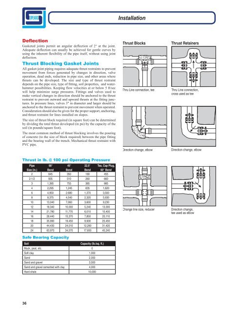
Installation<br />
Deflection<br />
Gasketed joints permit an angular deflection of 2° at the joint.<br />
Adequate deflection can usually be achieved for gentle curves by<br />
using the inherent flexibility of the pipe itself, without using joint<br />
deflection.<br />
Thrust Blocking Gasket Joints<br />
All gasket-joint piping requires adequate thrust restraints to prevent<br />
movement from forces generated by changes in direction, valve<br />
operation, dead ends, reduction in pipe size, and other areas where<br />
thrusts can be developed. <strong>The</strong> size and type of thrust restraint<br />
depends on the pipe size, type of fitting, soil properties, and waterhammer<br />
possibilities. Keeping flow velocities at or below 5 ft/sec<br />
will help minimize surge pressures. Fittings and valves used to<br />
make vertical changes in direction should be anchored to the thrust<br />
restraint to prevent outward and upward thrusts at the fitting junctures.<br />
In pressure lines, valves 3" in diameter and larger should be<br />
anchored to the thrust restraint to prevent movement when operated.<br />
Consideration should also be given for the proper support, anchoring,<br />
and thrust restraint for lines installed on slopes.<br />
<strong>The</strong> size of thrust block required (in square feet) can be determined<br />
by dividing the total thrust developed (in psi) by the capacity of the<br />
soil (in pounds/square foot).<br />
<strong>The</strong> most common method of thrust blocking involves the pouring<br />
of concrete (to the size of block required) between the pipe fitting<br />
and the bearing wall of the trench. Mechanical thrust restraint with<br />
PVC pipe.<br />
Thrust Blocks<br />
Thru Line connection, tee<br />
Direction change, elbow<br />
Thrust Retainers<br />
Thru Line connection,<br />
cross used as tee<br />
Direction change, elbow<br />
Thrust in lb. @ 100 psi Operating Pressure<br />
Pipe<br />
Size (in.)<br />
90°<br />
Bend<br />
45°<br />
Bend<br />
22.5°<br />
Bend<br />
Tee, Cap Plug,<br />
60° Bend<br />
2 645 350 180 455<br />
2-1/2 935 510 260 660<br />
3 1,395 755 385 985<br />
4 2,295 1,245 635 1,620<br />
6 4,950 2.680 1,370 3,500<br />
8 8,375 4,540 2,320 5,930<br />
10 13,040 7,060 3,600 9,230<br />
12 18,340 10,000 5,240 13,000<br />
14 21,780 11,770 6,010 15,400<br />
16 28,440 15,370 7,850 20,110<br />
18 35,990 19,450 9,930 25,450<br />
20 44,430 24,010 12,260 31,420<br />
24 63,970 34,570 17,650 45,240<br />
Safe Bearing Capacity<br />
Soil<br />
Capacity (lb./sq. ft.)<br />
Muck, peat, etc. 0<br />
Soft clay 1,000<br />
Sand 2,000<br />
Sand and gravel 3,000<br />
Sand and gravel cemented with clay 4,000<br />
Hard shale 10,000<br />
Change line size, reducer<br />
Direction change,<br />
tee used as elbow<br />
36