Applications for IL700, IL200, IL500, and IL600 ... - NVE Corporation
Applications for IL700, IL200, IL500, and IL600 ... - NVE Corporation
Applications for IL700, IL200, IL500, and IL600 ... - NVE Corporation

Create successful ePaper yourself
Turn your PDF publications into a flip-book with our unique Google optimized e-Paper software.
Application Bulletin AB-16<br />
<strong>Applications</strong> <strong>for</strong> IL800, <strong>IL700</strong>, <strong>IL200</strong>, <strong>IL500</strong>, <strong>and</strong> <strong>IL600</strong> Series Digital Isolators<br />
One of the most frequently asked questions at the isolator applications desk is “what’s the difference<br />
between <strong>NVE</strong>’s digital isolator families?” This application note sheds some light on the design differences<br />
between the various model families, why those differences are important, <strong>and</strong> where the individual products<br />
are best used. There are naturally some applications <strong>for</strong> digital isolators that overlap the families offered, but<br />
in general, some products are better used in some categories than others. By the time you’ve read this<br />
bulletin, you’ll know why.<br />
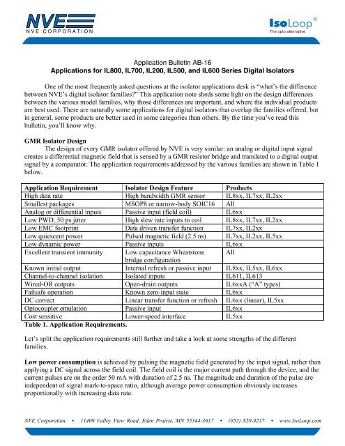
GMR Isolator Design<br />
The design of every GMR isolator offered by <strong>NVE</strong> is very similar: an analog or digital input signal<br />
creates a differential magnetic field that is sensed by a GMR resistor bridge <strong>and</strong> translated to a digital output<br />
signal by a comparator. The application requirements addressed by the various families are shown in Table 1<br />
below.<br />
Application Requirement Isolator Design Feature Products<br />
High data rate High b<strong>and</strong>width GMR sensor IL8xx, IL7xx, IL2xx<br />
Smallest packages MSOP8 or narrow-body SOIC16 All<br />
Analog or differential inputs Passive input (field coil) IL6xx<br />
Low PWD, 50 ps jitter High slew rate inputs to coil IL8xx, IL7xx, IL2xx<br />
Low EMC footprint Data driven transfer function IL7xx, IL2xx<br />
Low quiescent power Pulsed magnetic field (2.5 ns) IL7xx, IL2xx, IL5xx<br />
Low dynamic power Passive inputs IL6xx<br />
Excellent transient immunity Low capacitance Wheatstone All<br />
bridge configuration<br />
Known initial output Internal refresh or passive input IL8xx, IL5xx, IL6xx<br />
Channel-to-channel isolation Isolated inputs IL611, IL613<br />
Wired-OR outputs Open-drain outputs IL6xxA (“A” types)<br />
Failsafe operation Known zero-input state IL6xx<br />
DC correct Linear transfer function or refresh IL6xx (linear), IL5xx<br />
Optocoupler emulation Passive input IL6xx<br />
Cost sensitive Lower-speed interface IL5xx<br />
Table 1. Application Requirements.<br />
Let’s split the application requirements still further <strong>and</strong> take a look at some strengths of the different<br />
families.<br />
Low power consumption is achieved by pulsing the magnetic field generated by the input signal, rather than<br />
applying a DC signal across the field coil. The field coil is the major current path through the device, <strong>and</strong> the<br />
current pulses are on the order 50 mA with duration of 2.5 ns. The magnitude <strong>and</strong> duration of the pulse are<br />
independent of signal mark-to-space ratio, although average power consumption obviously increases<br />
proportionally with increasing data rate.<br />
<strong>NVE</strong> <strong>Corporation</strong> • 11409 Valley View Road, Eden Prairie, MN 55344-3617 • (952) 829-9217 • www.IsoLoop.com
Application Bulletin: AB-16<br />
The <strong>IL600</strong> Series has a linear magnetic transfer function. It is designed so a coil current of 5 mA flowing<br />
from the –In to +In terminal will cause the output to go low. When the input current falls to less than<br />
0.5 mA, the output will always go back to the high state. The <strong>IL600</strong> Series behaves exactly like an<br />
optocoupler in that regard <strong>and</strong> while its switching current requirement of 5 mA may appear high when<br />
compared to the other families at low frequencies (200 µA at 1 MHz), there is a crossover at approximately<br />
15 MHz when the IL6xx becomes the lowest average power user in the group. See Table 2 <strong>for</strong> an overview<br />
of “per channel” power consumption with 3.3 V supplies.<br />
Data Rate (Mbps) IL2xx IL6xx IL5xx IL7xx IL8xx<br />
2 0.7 8 0.8 0.7 1.3<br />
40 14 11 N/A 14 15<br />
100 40 15 N/A 40 40<br />
Table 2. No-Load Power Consumption in mW per channel at 3.3V.<br />
High Data Rate comes free with GMR circuits due to the 2 GHz b<strong>and</strong>width of the sensor. The speedlimiting<br />
factor in <strong>NVE</strong> isolators is the CMOS interface circuitry. IL8xx, IL7xx, <strong>and</strong> IL2xx have the fastest<br />
electronics. Slower electronics in the <strong>IL500</strong> Series reduce their cost. With data rates ranging from 2 Mbps to<br />
as high as 150 Mbps, there’s an <strong>NVE</strong> isolator <strong>for</strong> every speed requirement.<br />
Low PWD <strong>and</strong> jitter are again a function of the GMR switching element’s b<strong>and</strong>width, but with the<br />
additional consideration of perfect symmetry. Unlike transistors, it is as easy to switch a GMR element “on”<br />
as it is to switch it “off.” In the on state, the resistance of the GMR element is approximately 5% greater than<br />
the off state. GMR switching symmetry is largely independent of b<strong>and</strong>width. <strong>NVE</strong> uses precision laser<br />
trimming of the thin film GMR pattern to null the GMR bridge offset voltage. The process produces isolators<br />
with typically less than 1 ns PWD <strong>and</strong> only 50 ps jitter.<br />
<strong>NVE</strong> Isolators have a low EMC footprint because the input data is transferred directly across the isolation<br />
barrier with no RF carriers or refresh clocks. Trans<strong>for</strong>mer, capacitive, <strong>and</strong> RF isolation techniques require<br />
internal, asynchronous data clocks in the transfer function, resulting in much higher EMI emissions.<br />
The excellent transient immunity specification of 30 kV/µs minimum (50 kV/µs typical) <strong>for</strong> digital input<br />
<strong>NVE</strong> Isolators results from their symmetrical, cross-coupled Wheatstone bridge configuration.<br />
Analog, differential analog <strong>and</strong> differential digital signals can all be isolated directly with <strong>IL600</strong>-Series<br />
Isolators. These devices provide access to the internal field coil, meaning the user can steer current into the<br />
device to isolate many different signal types. For instance, RS-422, RS-485 <strong>and</strong> RS-232 differential signals<br />
can all be isolated directly without a separate RS-xxx receiver. An external resistor in the coil path limits<br />
current to 5 mA.<br />
In addition, low-voltage digital signals (1.2 V to 2.8 V) can be input on the coil side <strong>and</strong> translated to 3 V or<br />
5 V levels with ease. The fact that <strong>IL600</strong>-Series devices are current, not voltage, driven means any signal at<br />
any voltage level (specified up to 400 V rms ) can be connected to the coil input, limited to 5 mA with a<br />
resistor <strong>and</strong> transferred to the output as an isolated digital signal. The channel-to-channel isolation feature<br />
of this family makes it easy to isolate multiple signals from different grounds <strong>and</strong> present the isolated outputs<br />
to a common controller such as a PLC in the industrial environment, or a supply alarm monitor in a telecom<br />
base station. The ultra-miniature MSOPs enable space savings not available in any other isolator <strong>for</strong>mat. If<br />
2
Application Bulletin: AB-16<br />
wired-OR functionality is needed in an alarm application, the open-drain options available in the<br />
<strong>IL600</strong> Series allow outputs to be tied to a single pull-up resistor, eliminating the open collector logic gate<br />
normally required with other isolators.<br />
Failsafe operation, the requirement that isolator outputs must be in a defined state if input power is lost, is<br />
available in the <strong>IL600</strong> Series. This function, along with DC correct operation, is usually required in<br />
applications where an incorrect output level after input supply failure could result in contentious circuit<br />
operation. For example, a CAN control node could be stuck in the dominant mode (logic low), effectively<br />
halting the system. Similarly, the DC-correct function allows users who need to know output states at<br />
power-up to confidently design their systems knowing the output will always follow the input. <strong>NVE</strong>’s IL800<br />
<strong>and</strong> <strong>IL500</strong> Series have internal refresh clocks, meaning outputs can be guaranteed after the first clock pulse<br />
has been issued. Some part types also have external SYNC lines that can be connected to a st<strong>and</strong>ard Power-<br />
On Reset pulse to ensure output conditions immediately after reset is asserted.<br />
True optocoupler emulation can be achieved using the <strong>IL600</strong> Series. The venerable opto has been used in<br />
so many applications it’s impossible to list them all. Most opto replacement products, however, are digital<br />
input devices, meaning only opto applications with digital inputs can be replaced without redesign of the<br />
input signal network. The IL6xx has direct optocoupler connectivity, so any input <strong>for</strong>mat used by<br />
optocouplers can also be used by the IL6xx without redesign. Don’t <strong>for</strong>get the additional advantage in the<br />
passive input structure of the IL6xx versus a typical opto diode input—unlike the diode, there’s no need to<br />
protect the coil against reverse bias. Any reverse voltage on the coil pins simply serves to push the isolator<br />
further into the off state. The differential signaling technique mentioned above uses this unique feature.<br />
For cost-sensitive applications, you can’t beat the <strong>IL500</strong> Series. It represents the lowest possible cost <strong>for</strong><br />
GMR isolators <strong>and</strong> is great <strong>for</strong> those sub-megahertz applications previously served by low-end optocouplers.<br />
In addition, multi-channel configurations <strong>and</strong> small packages make it a natural <strong>for</strong> reducing PCB size <strong>and</strong><br />
cost while retaining opto functionality.<br />
3<br />
ISB-AP-16; rev. August 2014