3-axis magnetometers using spin dependent tunneling: reduced ...
3-axis magnetometers using spin dependent tunneling: reduced ...
3-axis magnetometers using spin dependent tunneling: reduced ...

Create successful ePaper yourself
Turn your PDF publications into a flip-book with our unique Google optimized e-Paper software.
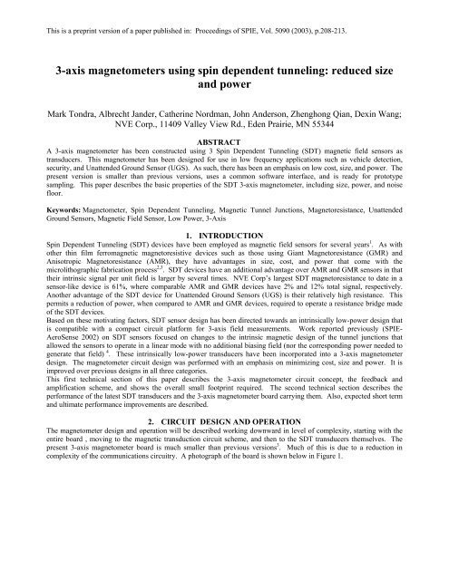
This is a preprint version of a paper published in: Proceedings of SPIE, Vol. 5090 (2003), p.208-213.layers of Al metal for interconnection and integrated planar coils, the SDT devices themselves, and some plated NiFeflux concentrators. Once the wafers are finished, they are diced and sent to a packaging house where they are diced,wire bonded, and molded into standard integrated circuit packages. A diagram and photograph of a finished SDT sensorchip is shown below in Figure 3. Automated testing of packaged parts allows for rapid winnowing away of lesserperformingparts. The SDT parts are mounted on and soldered to a printed circuit board just like any other chip. Themagnetic operation of the sensors is described elsewhere (SPIE AeroSense 2002) 3 .Pin 8Pin 7Pin 6Pin 5V +OUT +OC -OC+top down viewBridgeR4R3R1R2NVE(100141)ParallelField CoilOC1OC2OrthogonalField Coilsensitive<strong>axis</strong>PC2PC1OUT-V -PC -PC +Pin 1Pin 2Pin 3Pin 1Figure 3. The drawing on the left shows schematically the components that are contained within the SDT sensor package. Thephotograph on the right is of an SDT sensor die packaged in an SOIC-8-pin package. The package material in this case is clear, whichallows one to see the die, wirebonds, and bonding pads of the finished device.3. PERFORMANCEThis section will discuss the performance of the 3-<strong>axis</strong> SDT magnetometer in terms of power, and noise. The SDTtransducer itself has the greatest influence on both power and noise. The SDT transfer curve, a plot of Output Voltagevs. Magnetic Field, is described in section 3.1. The noise performance of the board is described in section 3.2. Then arediscussed the power and overall specifications for the board.1. Transducer Transfer CurveThe SDT low-power transducer curve has been evolving towards an ideal shape over the past several years. In this case,“ideal” means a wide range of field over which the output is linear with little or no hysteresis. Further, the transfer curveshould be centered on zero field and zero volts. The curve shown in Figure 4 below comes close to this ideal. There isstill some hysteresis and offset. The offset occurs both in voltage and field. The voltage offset is from a mismatch of theresistors in the transducer bridge (offset of .05 Volts out of 5V excitation = 1%offset). The field offset is a function ofthe sensor’s magnetic design. There are efforts underway to continue reducing these non-idealities. The transducerscome in two designs, a 60 kOhm (6 Volt max) and a 300 kOhm (12 Volt max). These designs vary in the number andsize of the tunnel junctions that make up the resistance bridge.
This is a preprint version of a paper published in: Proceedings of SPIE, Vol. 5090 (2003), p.208-213.0.2Bridge Output (Volts) [5 V excitation]0.150.10.050-6 -4 -2 0 2 4 6-0.05-0.1Field (Oe)Figure 4. Transfer curve for low power SDT sensor. This is a measurement of the 4-terminal bridge output. That is, a 5 Volt supplyis applied from the top of the bridge to ground, and the voltage between the other two bridge leads is monitored and plotted as afunction of applied magnetic field. The field starts at +6 Oe, sweeps to –6 Oe and then back to +6 Oe.2. Noise FloorThe sensor noise floor is dominated, at low frequencies (below 1 kHz), by “1/f” noise. The “1/f” refers to the functionalrelationship between the noise power (V 2 / Hz) and frequency. The noise is fundamentally related to resistancefluctuations in the tunnel junctions. Because the signal due to an external field also appears as a resistance change,electrical “chopping” is not an effective technique for removing it. Rather, only “magnetic chopping” can allow thesignal to noise floor to be lower than the 1/f noise present in a DC field measurement. Magnetic chopping means, inpractice, either changing the amplitude of the otherwise steady external field, or changing the magnetic characteristics ofthe SDT transducer in time. Such magnetic chopping is possible, and has been shown to improve the signal to noiseratio (S/N) for SDT sensors. For this application, however, it was decided that the power and complexity of choppingcircuitry was not worth the improvement in S/N. The noise floor for all three axes of the 3-<strong>axis</strong> SDT magnetometer areshown below in Figure 5. Note the strong 1/f behavior. The plot below is in units of Tesla / sqrt. Hz. One nanoTesla =10 -5 Gauss = 10 -5 Oersted. These data are obtained by measuring the noise in Volts / sqrt. Hz and dividing by thetransducer slope (Volts / Tesla). Since the field noise goes as the voltage rather than the voltage squared, the 1/f noiseappears as 1 / sqrt. f in this plot.
This is a preprint version of a paper published in: Proceedings of SPIE, Vol. 5090 (2003), p.208-213.Figure 5. Noise spectral density vs. frequency. The units of noise are Tesla / sqrt. Hz. This means that one must multiply the noisespectral density by the square root of the measurement bandwidth to get the root-mean-square noise at a given measurementfrequency.3. Power RequirementsThe power requirements for the 3-<strong>axis</strong> SDT magnetometer are shown in Table 1 below. For the present mode ofoperation the largest power user is the field feedback. The power required for feedback is specified in mW per Oe for agiven transducer. For example, measuring the ambient earth’s field, which has a vector magnitude of about 0.7 Oe,requires approximately 50 mW if the field is oriented along the sensing <strong>axis</strong> of one of the transducers. Note that the totalpower required for feedback will vary with orientation (the worst case being when the field is oriented with equalcomponents in each axial direction where the total would be 90 mW).Table 1:Sensor bridges0.5 mWOp-amps2 mWA/D converters3 mWMicrocontroller10 mWSerial I/O20 mWFeedback coil drive75 mW per Oe------------------------------------------------------------Total~100 mW (typical in earth’s field)4. Overall SpecificationsThe specifications for the 3-<strong>axis</strong> SDT magnetometer are shown below in Table 2. The digital resolution is 0.1 nT with afull scale range of 0.2 mT. In practice, the resolvable signal is limited by the intrinsic sensor noise shown in Fig. 5. Forexample, for a signal frequency of 1 Hz, the system noise level is approximately 1 nT per square root bandwidth. Thesample rate is user selectable over a range of 10 Hz to 125 Hz. All three axes are sampled simultaneously. Commandsare sent to the magnetometer and data is transmitted over a standard RS232 serial interface. A multi-drop RS485protocol is also supported to allow bussing of multiple units.
This is a preprint version of a paper published in: Proceedings of SPIE, Vol. 5090 (2003), p.208-213.Table 2:Field Range:+/- 0.2 mT ( 2 Gauss)Noise level:~ 1 nT/√HZ at 1 HzDigital Resolution: 0.1 nT (24 bit)Sample rate:10 Hz - 125 HzPower:100 mW (typical, for all axes combined)Interface :RS232, RS485Cost : ~$100 / magnetometer (in quantities >= 10,000)4. DISUCSSION AND CONCLUSIONSThe 3-<strong>axis</strong> SDT magnetometer is a fully functional prototype with a standard software command set for serial computerinterface. It has the benefit of several iterations of development, both of the SDT transducer and the circuit. However,there are many aspects of the magnetometer that are the subject of ongoing and intense improvement. Here we brieflyoutline these efforts, and make an estimate of the ultimate possible performance at some later date.1. Lower Feedback PowerThe feedback power can be <strong>reduced</strong> in several ways. One elegant method under development is the fabrication of afeedback coil on the SDT transducer chip that physically goes around the on-chip NiFe flux concentrators. Thee existingversions are planar coils. The gain in field per unit power would be on the order 10, bringing the feedback power donwnfrom ~100 mW to ~10 mW. Another intermediate step is to reconfigure the magnetometer to operate with no fieldfeedback coil. This would sacrifice some performance in linearity and hysteresis. This may, at times, be an acceptabletrade since the feedback is the largest power consumer.2. Signal to NoiseThe noise floor of the SDT transducer is still far from optimized. Efforts over the past two years, which have focused onreducing overall power consumption, are moving back to increasing the signal and reducing intrinsic noise. Continuingrefinements of the magnetic thin films that respond to the external field, and the micromagnetic design, are expected tocontribute ~10x in signal per unit field. The 1/f noise is a stubborn problem that, if solved, could reduce the noise at lowfrequency by ~ 100x. Thus, the overall fully optimized noise floor will approach 1 pT/ sqrt. Hz.The authors would like to acknowledge guidance and assistance from a number of people including John Taylor, JimDaughton, Bob Schneider, and Bob Sinclair, all of NVE; Alan Edelstein, Jonathan Fine, and at ARL Adelphi; and AmyHermann and Dick Mabry of Eglin AFB. The work described here was supported by SBIR funding from the Army,Navy, Air Force, and DARPA. The authors are grateful for this generous support.5. REFERENCES1. M. Tondra, J.M. Daughton, D. Wang, R. Beech, A. Fink, and J. Taylor, “Picotesla field sensor design <strong>using</strong> <strong>spin</strong><strong>dependent</strong><strong>tunneling</strong> devices,” J. Appl. Phys., vol. 83, pp. 6688-6690 (1998).2. M. Tondra, Unattended Ground Sensors and Technologies III, E. Carapezza, editor. Proceedings of the SPIE, Vol.4393 (2001).3. M. Tondra, A. Jander, C. Nordman, “Low-power 3-<strong>axis</strong> <strong>magnetometers</strong> <strong>using</strong> <strong>spin</strong> <strong>dependent</strong> <strong>tunneling</strong> for UGSand security applications,” Proceedings of the SPIE, Vol. 4743, pp. 188-196, (2002).4. P. V. Czipott, Y. Dalichaouch, A. R. Perry, “Magnetoresistive sensors for small and low-powered UnattendedGround Sensor Applications”, Proceedings of the SPIE, Vol. 4743, pp. 197-204, (2002).