High Voltage Testing Standards Overview - NVE Corporation
High Voltage Testing Standards Overview - NVE Corporation
High Voltage Testing Standards Overview - NVE Corporation

Create successful ePaper yourself
Turn your PDF publications into a flip-book with our unique Google optimized e-Paper software.
Application Bulletin AB-2<br />
Isolator <strong>High</strong> <strong>Voltage</strong> Safety <strong>Standards</strong><br />
IsoLoop Isolators have exceptional high-voltage performance and meet applicable safety standards. The standards<br />
summarized in this Bulletin are UL 1577, IEC 61010-1, VDE 0884, IEC 60747-5-5, and IEC 60601-1.<br />
UL 1577<br />
UL 1577 focuses on voltage breakdown, defined as a high leakage current. There is a destructive test on lot<br />
samples and a nondestructive production test on each part.<br />
The destructive test requires the device to withstand the isolation voltage (typically 2500 or 5000 V RMS ) for one<br />
minute. The production test is 120% of the rated isolation voltage without breakdown for one second.<br />
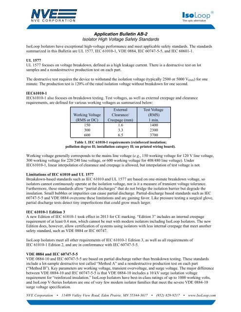
IEC61010-1<br />
IEC61010-1 also focuses on breakdown testing. Test voltages, as well as external creepage and clearance<br />
requirements, are defined for various working voltages as summarized below:<br />
Working <strong>Voltage</strong><br />
(RMS or DC)<br />
External<br />
Clearance/<br />
Creepage (mm)<br />
Test <strong>Voltage</strong><br />
(RMS)<br />
1 min.<br />
150 1.6 1400<br />
300 3.3 2300<br />
600 6.5 3700<br />
Table 1. IEC 61010-1 requirements (reinforced insulation;<br />
pollution degree II; installation category II; on printed wiring board).<br />
Working voltage generally corresponds to the mains line voltage (e.g., 150 working voltage for 120 V line voltage,<br />
300 working voltage for 220/240 line voltage, or 600 working voltage for 408/480 line voltage). Under<br />
IEC61010-1, linear interpolation of clearance and creepage is allowed, but interpolation of test voltage is not.<br />
Limitations of IEC 61010 and UL 1577<br />
Breakdown-based standards such as IEC 61010 and UL 1577 are based on one-minute breakdown voltage, so<br />
isolators cannot continuously operate at the isolation voltage, nor is it a measure of transient voltage tolerance.<br />
Furthermore, these standards allow “partial discharges” that do not bridge the isolation barrier but degrade the<br />
insulation. Small bubbles or impurities can cause partial discharge. Partial-discharge based standards such as IEC<br />
60747-5-5 and VDE 0884 overcome these limitations and are gaining favor. Like pressure testing a surgical glove,<br />
partial discharge tests detect tiny imperfections that could grow much larger.<br />
IEC 61010-1 Edition 3<br />
A new Edition of IEC 61010-1 took effect in 2013 for CE marking. “Edition 3” includes an internal creepage<br />
requirement of at least 0.4 mm, which cannot be met with modern isolators including IsoLoop Isolators. The new<br />
Edition does, however, allow certification of systems using isolators with less internal creepage that meet another<br />
safety standard, such as VDE 0884 or IEC 60747.<br />
IsoLoop Isolators meet all other requirements of IEC 61010-1 Edition 3, as well as all requirements of<br />
IEC 61010-1 Edition 2, and are in conformance with IEC 60747-5-5.<br />
VDE 0884 and IEC 60747-5-5<br />
VDE 0884-10 and IEC 60747-5-5 are based on partial discharge rather than breakdown testing. These standards<br />
include a lot-sample destructive test called “Method A” and a nondestructive production test on each part<br />
(“Method B”). Key parameters are working voltage, transient overvoltage, and surge voltage. The major difference<br />
between VDE 0884-10 and IEC 60747-5-5 is that VDE 0884-10 includes a 10 kV surge isolation voltage<br />
requirement for “reinforced insulation.” IsoLoop Isolators have best-in-class ratings of up to 1000 working volts,<br />
and IsoLoop V-Series Isolators are one of very few modern isolator families that meet the severe VDE 0884-10<br />
surge voltage specification.<br />
<strong>NVE</strong> <strong>Corporation</strong> • 11409 Valley View Road, Eden Prairie, MN 55344-3617 • (952) 829-9217 • www.IsoLoop.com
Application Bulletin: AB-2<br />
VDE 0884/IEC 60747-5-5 Lot-Sample <strong>Testing</strong><br />
Type testing combines transient overvoltage and partial discharge tests as illustrated in Fig. 1:<br />
V ini<br />
t ini = 60 sec.<br />
t m = 10 sec.<br />
V m<br />
V IORM<br />
t ini t m<br />
V m = 1.5 x V IORM<br />
Figure 1. VDE 0884 “Method A” (destructive) testing.<br />
V IORM is defined as the rated peak working voltage, V ini is the rated transient overvoltage, and V m is the partial<br />
discharge test voltage. In the initial test phase, the transient overvoltage test phase, the test voltage is ramped to<br />
V INITIAL for 60 seconds (t ini ). Partial discharge is allowable, but not breakdown. The voltage is then decreased to the<br />
partial discharge test voltage, V m , which is 1.5 x V IORM . The partial discharge test time is 10 seconds (t m ), and the<br />
partial discharge threshold is 5 picocoulombs.<br />
VDE 0884-10 Surge <strong>Voltage</strong><br />
VDE 0884-10 specifies a minimum surge voltage (V IOSM ) rating of 10 kV. Parts must withstand repetitive pulses at a<br />
rate of one per second with the waveform shown below:<br />
V IOSM<br />
V IOSM = 10 kV<br />
90% V IOSM<br />
One pulse per second<br />
50% V IOSM<br />
10% V IOSM<br />
50 s<br />
1.2 s<br />
Figure 2. VDE 0884 / IEC 61000-4-5 Surge <strong>Voltage</strong> test waveform.<br />
VDE 0884-10 Service Class<br />
Service Class under partial discharge standards is determined by the required working voltage and the transient<br />
overvoltage (see Table 2). Standard IsoLoop Isolators have a rated working voltage of 600 V RMS and a transient<br />
overvoltage rating of 4000 V PK . V-Series Isolators have a rated working voltage of 1000 V RMS and a transient<br />
overvoltage rating of 6000 V PK . So for example, a working voltage of 300 V RMS is required for 220 V/240 V mains<br />
line voltage, and for that working voltage standard Isolators meet Service Class III and V-Series Isolators meet<br />
Service Class IV:<br />
2
Application Bulletin: AB-2<br />
Transient Overvoltage (V INITIAL ;V PK )<br />
Working <strong>Voltage</strong><br />
Working <strong>Voltage</strong><br />
Service Class<br />
V IORM (V RMS ) V IORM (V PK /V DC ) I II III IV<br />
150 212 800 1500 2500 4000<br />
300 414 1500 2500 4000 6000<br />
600 828 2500 4000 6000 8000<br />
1000 1415 4000 6000 8000 12000<br />
Table 2. VDE 0884-10 / IEC 60747-5-5 / IEC 60664 transient overvoltage requirements<br />
(light green indicates conformance with standard IsoLoop Isolators; dark green shows V-Series conformance).<br />
VDE 0884/IEC 60747-5-5 Production <strong>Testing</strong><br />
For nondestructive production testing, the test time is reduced to one second and the test voltage, V PR , is raised to<br />
1.875 x V IORM . The partial discharge threshold is 5 picocoulombs.<br />
VDE 0884/IEC 60747-5-5 Sample <strong>Testing</strong><br />
There are also random sample tests for visual defects, dielectric strength, validation of operation, creepage and<br />
clearance, insulation resistance, insulation resistance at elevated temperature, and soldering heat resistance.<br />
VDE 0884 Safety-Limiting Values<br />
“Safety-Limiting Values” are non-operating limits for the isolation barrier to continue to isolate the two potentials.<br />
Safety-limiting values for IsoLoop Isolators are summarized in the following table:<br />
Parameter Symbol Value Units<br />
Safety rating ambient temperature T S 180 °C<br />
Safety rating power (180°C) P S 270 mW<br />
Supply current safety rating (total of supplies) I S 54 mA<br />
Safety power derating<br />
3 mm MSOP-8<br />
0.15" SOIC-8<br />
0.15" QSOP-16<br />
0.15" SOIC-16<br />
0.3" SOIC-16<br />
Table 3. IsoLoop safety-limiting values.<br />
Because of the unique construction of their isolation barrier, IsoLoop isolators have an unusually high safety rating<br />
temperature and safety rating power. This is shown in the following curves:<br />
3<br />
80<br />
60<br />
60<br />
60<br />
60<br />
°C/W<br />
Safety Rating Power (W)<br />
2<br />
1<br />
MSOP<br />
All other packages<br />
0<br />
-20<br />
20 60 100 140 180<br />
Ambient Temperature (˚C)<br />
Figure 3. Safety rating power vs. temperature.<br />
3
Application Bulletin: AB-2<br />
IEC 60601-1<br />
IEC 60601 specifies isolator creepage and isolation voltage for medical safety, and its creepage measurement<br />
standards are also used for demanding non-medical applications. As shown in Table 4, standard IsoLoop Isolators<br />
meet IEC 60601 Type B, “one Means of Operator Protection,” and “one Means of Patient Protection”<br />
requirements. IsoLoop V-Series Isolators meet the most stringent requirements, including those for equipment in<br />
contact with the heart:<br />
Classification Isolation <strong>Voltage</strong> Creepage<br />
Type B (within patient vicinity) / 1 MOOP 1500 V RMS 2.5 mm<br />
Type BF (within patient vicinity) / 2 MOOP 3000 V RMS 5 mm<br />
1 MOPP 1500 V RMS 4 mm<br />
Type CF (contact with the heart) / 2 MOPP 4000 V RMS 8 mm<br />
Table 4. IEC 60601 requirements.<br />
IEC 60601-1 Creepage<br />
IEC 60601-1 has the most stringent creepage requirements of the applicable standards. For 220/240 V line voltage<br />
(250 V RMS working voltage) and the most stringent classification, creepage must be at least 8 mm. Unlike<br />
IEC 61010-1, IEC 60601 does not allow interpolation of values for clearance and creepage.<br />
The limiting creepage path is usually around the end of the package from pin 1 to 16 or pin 8 to 9. Ordinary<br />
JEDEC wide-body packages are nominally 7.4 mm wide, with approximately 8.1 mm between pins around the end<br />
before subtracting metal tabs (often called “tie bars”) on the package edge. Tie bars are used in the molding<br />
process, and whether internally connected or not, the exposed metal reduces the creepage and must be subtracted<br />
under IEC 60601. The tie bar subtraction for ordinary JEDEC packages is typically 0.5 mm, reducing typical<br />
creepage to only 7.4 mm even before allowing for mechanical tolerances:<br />
7.4 mm<br />
8.3 mm<br />
Figure 4. Typical True 8 creepage vs. an ordinary wide-body package.<br />
The <strong>NVE</strong> True 8 isolator package was custom tooled for isolation. Even with worst-case package dimensions<br />
and pin placement, the <strong>NVE</strong> package ensures 8 mm minimum creepage as defined under IEC 60601 rules.<br />
IsoLoop Approvals<br />
Specifics of IsoLoop Isolator approvals for UL 1577, IEC 61010-1, and IEC 60747-5-5 (VDE 0884) are<br />
summarized as follows:<br />
UL 1577 (Component Recognition Program File Number E207481)<br />
Standard parts tested at 3000 V RMS (4240 V PK ) for 1 sec.; each lot sample tested at 2500 V RMS (3530 V PK ) for 60 sec.<br />
V-Series parts tested at 6000 V RMS (8486 V PK ) for 1 sec.; each lot sample tested at 5000 V RMS (7072 V PK ) for 60 sec.<br />
IEC 61010-1 (Reinforced Insulation; Pollution Degree II; Material Group III; TUV Certificates N1502812; N1502812-101)<br />
IsoLoop Package Working <strong>Voltage</strong><br />
MSOP (standard)<br />
150 V RMS<br />
MSOP (high isolation voltage) 300 V RMS<br />
PDIP<br />
300 V RMS<br />
SOIC<br />
150 V RMS<br />
0.3" SOIC (standard) 300 V RMS<br />
0.3" SOIC (high isolation voltage) 1000 V RMS<br />
4
Application Bulletin: AB-2<br />
VDE 0884-10 (File Number 5016933-4880-0001; 5 kV-rated V-Series 0.3" SOIC parts)<br />
• Working voltage (V IORM ) 1000 V RMS (1415 V PK ); basic insulation; pollution degree 2<br />
• Transient overvoltage (V IOTM ) 6000 V PK<br />
• Surge voltage (V IOSM ) 10 kV PK<br />
• Each part tested at 2387 V PK for 1 second, 5 pC partial discharge limit<br />
• Samples tested at 6000 V PK for 60 sec.; then 2122 V PK for 10 sec. with 5 pC partial discharge limit<br />
IEC 60747-5-5 (VDE 0884) (File Number 5016933-4880-0001; 1 kV and 2.5 kV-rated parts)<br />
• Working <strong>Voltage</strong> (V IORM ) 600 V RMS (848 V PK ); basic insulation; pollution degree 2<br />
• Transient overvoltage (V IOTM ) and surge voltage (V IOSM ) 4000 V PK<br />
• Each part tested at 1590 V PK for 1 second, 5 pC partial discharge limit<br />
• Samples tested at 4000 V PK for 60 sec.; then 1358 V PK for 10 sec. with 5 pC partial discharge limit<br />
Other <strong>High</strong>-<strong>Voltage</strong> Parameters<br />
<strong>NVE</strong>’s unique polymer-ceramic composite barrier provides superior high-voltage performance. In addition to<br />
standards compliance, other best-in-class figures of merit are as follows:<br />
Parameter Min. Typ. Units Test Conditions<br />
Barrier Impedance (Insulation Resistance) 10 14 Ω<br />
Comparative Tracking Index (CTI) ≥175 V Per IEC 60112<br />
<strong>High</strong> <strong>Voltage</strong> Endurance<br />
(Maximum Barrier <strong>Voltage</strong> for Indefinite Life)<br />
AC<br />
DC<br />
1000<br />
1500<br />
V RMS<br />
V DC<br />
Barrier Life 44000 Years<br />
Table 5. IsoLoop high-voltage specifications.<br />
At maximum<br />
operating temperature<br />
100°C, 1000 V RMS ,<br />
60% CL activation energy<br />
5<br />
ISB-AP-02; rev. September 2014