very dense magnetic sensor arrays for precision ... - NVE Corporation
very dense magnetic sensor arrays for precision ... - NVE Corporation
very dense magnetic sensor arrays for precision ... - NVE Corporation

You also want an ePaper? Increase the reach of your titles
YUMPU automatically turns print PDFs into web optimized ePapers that Google loves.
they have poor temperature compensation and usuallyrequire the <strong>for</strong>mation of some type of bridge by usingexternal components. Alternatively they can be connectedin series with one differential amplifier per <strong>sensor</strong> resistor.Half bridges take up more area on a chip but offertemperature compensation, as both resistors are at the sametemperature. Half bridges can be used as field gradient<strong>sensor</strong>s if one of the resistors is some distance from theother. They can function as field <strong>sensor</strong>s if one of theresistors is shielded from the applied field.Metal 2 withvias to Metal 1Metal 1 withvias to GMRMetal 1GMRelementsOutV +GndBiasFigure 4 shows a portion of an array of 16 GMR halfbridgeelements with 5 µm spacing. The elements are 1.5µm wide by 6 µm high with a similar size element abovethe center tap. The bottoms of the stripes are connected toa common ground connection and the tops of the halfbridges are connected to a current supply. The center tapsare connected to 16 separate pads on the die. A bias strappasses over the lower elements to provide a <strong>magnetic</strong> fieldto bias the elements.Figure 5. Four individual elements of a 16-element array ofGMR half-bridge <strong>sensor</strong>s with 15 µm spacing. The firstelements are shown without metal 1 and metal 2 layersand without metal 1 layers <strong>for</strong> clarity.An example of a bio<strong>sensor</strong> array is shown in Figure 6.This bio<strong>sensor</strong> has twenty individual <strong>sensor</strong> elements in a4x5 matrix. The resistance of each element can beindividually measured.Metal 2 withvias to Metal 1Metal 1 withvias to GMRGMRelementsMetal 1V +OutBiasGndFigure 4. Part of a 16-element array of GMR half-bridge<strong>sensor</strong>s with 5 µm spacing. The first three elementshave portions removed to show the three layers andtheir interconnections.Wider spacing between the elements can be achievedwhile retaining the directional sensitivity of narrow stripesby using serpentine resistors as the lower elements. Figure5 shows the layout <strong>for</strong> a wider 16-element array with 15 µmspacing. Serpentine resistors with 4 stripes are used <strong>for</strong> thelower <strong>sensor</strong> element, and a single, longer stripe <strong>for</strong> theupper element. For clarity of the interconnections betweenlayers, some of the elements are shown without metal 1 andmetal 2 layers.Figure 6. A bio<strong>sensor</strong> array of 20 GMR elements arrangedin a 4x5 matrix.3
Sensor UnderlayersGMR and SDT materials are usually deposited on SiNinsulating coatings over Si wafers. GMR materials havealso been successfully integrated with both BiCMOS andbipolar semiconductor underlayers. This integration hasbeen demonstrated in both integrated <strong>sensor</strong>s and in<strong>magnetic</strong> couplers or isolators. A major obstacle thatneeded to be overcome was the planarization of theelectronics underlayer to obtain the necessary “smoothness”<strong>for</strong> successful <strong>sensor</strong> depositions. Figure 7, an AtomicForce Microscopy (AFM) image of the electronicsunderlayer, shows the roughness of the substrate be<strong>for</strong>e theplanarization required <strong>for</strong> integrated <strong>sensor</strong> arraydeposition.roughness has been reduced from 2.9 nm to 0.2 nm. Thelarge individual peaks are probably debris.Another method of planarizing <strong>sensor</strong> underlayers,especially between layers of metalization such asinterconnects and on-chip coils have been deposited is touse spin-on organic insulators such as BCB. Figure 9shows the cross section of an SDT <strong>sensor</strong> with severallayers of metal <strong>for</strong> interconnects and field coils. Note theBCB insulation layers.shield / flux concentratorNiFe 14 µm1500 Å Si Nitride(Au 2 µm)1000 Å seed layer (NiFeCo) --also use as hard mask <strong>for</strong> BCB etchBCB ~2 µm500 Å silicon nitride surface sealing layerM3 1.8 µmCrSi 150 Å1500 Å Si NitrideBCB ~2 µmFigure 7. Atomic <strong>for</strong>ce Microscope (AFM) image showingthe surface roughness of a substrate be<strong>for</strong>eplanarization. RMS roughness 2.9 nm.M31.8 µmM2 1.8 µmM1 0.5µm500 Å Si nitride surface sealing layer1500 Å Si NitrideBCB~2 µm500 Å silicon nitride surface sealing layerwindow nitride 2500ÅFigure 9. Cross section of SDT <strong>sensor</strong> showing BCBinsulation used to planarize layers between metaldepositions.Signal ProcessingCrSi150 Å2k Å silicon nitride LPCVDsilicon waferM2 1.8 µmM1CrSi 150 ÅAl 200 ÅCrPtMnFeCo/Ru/FeCoNiFe 120 Å Al2O3 barrierA block diagram of the data acquisition system <strong>for</strong>monitoring a 16-element array such shown earlier is shownin Figure 10. Two 8-channel multiplexers (AD 7501 & AD7503) are combined <strong>for</strong> 16-channel selection. This circuitis made possible by using multiplexers with the samespecifications and pin configurations where one of themhas an enable input that is active ‘true’ and the other isactive ‘false’. Because the output impedance is high in thedisabled state, the outputs from the multiplexers can bedirectly connected. A host computer provides control usinga nonlatched (no handshaking) digital signal using 4 bits ofa single port on the AT MIO16X, series E, data acquisitionboard.Figure 8. AFM image showing the surface roughness of asubstrate after CMP Planarization. RMS roughness 0.2nm.A similar substrate after chemical mechanicalpolishing <strong>for</strong> 10 minutes is shown in Figure 8. The rms4
Enable8 elementarraySensing currentHostAD7501Device selectV refV outAT MIO16Xseries E I/OAD7503O/PBand-passfilterMultiplexed sense current and output3 bit data busLock-inamplifierV +X and Y signalsFigure 10. Block diagram of the multiplexed dataacquisition system <strong>for</strong> multiplexing a 16-element GMRarray.Device selectV refV outData acquisition systems can also include digitizersand control. The system shown in Figure 11 takes thesignals from 64 <strong>sensor</strong>s in an array <strong>for</strong> biosensing,multiplexes them to an amplifier, and digitizes them. Thecomputer controls the current to an electromagnet whichapplies an ac <strong>magnetic</strong> bias to the sensing elements.Multiplexed output, Parallel sense currentFigure 12. Schematics of multiplexed data acquisition byon-chip FETs. Either the sense current or the outputcan be multiplexed.ApplicationsEdge Connector64 x 1MultiplexerGMR Array ChipDiff.Amp.Digitizer BoardConnector Board12 BitA to DConverterCoil BoardCurrentAmpLaptop / PCFigure 11. Data acquisition system <strong>for</strong> a 64-elementbio<strong>sensor</strong> array. Computer control of applied <strong>magnetic</strong>field is also shownOn-chip multiplexing of <strong>sensor</strong>s reduces the numberof connections to the chip. The multiplexing can beaccomplished by using FETs to select the device to beconnected to an external digitizer as is shown in Figure 12.Multiplexing can be accomplished by selecting the <strong>sensor</strong>to which the sensing current is directed or by using parallelsense current and multiplexing the output.Imaging of <strong>magnetic</strong> media – There are a variety ofapplications that utilize <strong>arrays</strong> of <strong>magnetic</strong> <strong>sensor</strong>s to <strong>for</strong>mimages of various types of <strong>magnetic</strong> media. In<strong>for</strong>mationrecorded on audiotapes by simple tape recorders and eventelephone answering machines has played important rolesin legal cases. It is important to ascertain whether theserecordings are genuine or have been edited. Direct imagingof the <strong>magnetic</strong> patterns on the tape surface can revealstarts and stops and erasures. In some cases, <strong>magnetic</strong>imaging can recover in<strong>for</strong>mation that was erased and is nolonger available in audio playback. The originalin<strong>for</strong>mation may remain as patterns bordering the erasehead or even may be recovered as a faint image in theerased section. Research has been done at the NationalInstitute of Standards and Technology (NIST) in Boulder,Colorado on methods to recover this seemingly lostin<strong>for</strong>mation. 7 An image is slowly acquired one scan at atime using a commercial magnetoresistive read head from acomputer hard drive. Magnetic <strong>sensor</strong> <strong>arrays</strong> cantremendously reduce the time to acquire such in<strong>for</strong>mationand bring this technology out of the research laboratory andinto the <strong>for</strong>ensic laboratory. 8Magnetic imaging using high-resolution <strong>arrays</strong> of<strong>magnetic</strong> <strong>sensor</strong>s has many potential uses in commerce.5
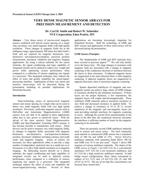
Personal computers and high quality color printers andcopiers have made detection of counterfeit currency anincreasing worldwide problem. 9 Magnetic fields areproduced by magnetized small particles of iron oxidecommonly used in black ink. These small fields canproduce signatures when read by <strong>magnetic</strong> <strong>sensor</strong>s that canbe used to identify the denominations of currency presentedto vending machines and bank sorting machines. Thesignature of additional <strong>magnetic</strong> in<strong>for</strong>mation encoded intomany counties’ currencies can be used to distinguish validcurrency from copies. At present <strong>magnetic</strong> signatures areread by one, or at the most a few, <strong>magnetic</strong> <strong>sensor</strong>s as a billpasses a detection head. Optical detectors are used toobtain a more complete image of the bill. High-resolutionGMR <strong>sensor</strong> <strong>arrays</strong> could obviate the need <strong>for</strong> opticalimaging by providing a <strong>magnetic</strong> image of the bill.The <strong>magnetic</strong> imaging of currency is difficult becausethe low fields produced by the <strong>magnetic</strong> ink. Themaximum field measured immediately above U. S.currency is less than 100 mOe or 8 A/m. Inductive readheads designed similarly to tape recorder heads need to bein direct contact to yield an adequate signal from U. S.currency. Similarly, present commercially availablemagnetoresistive currency detection heads must be in directcontact with the passing currency. To avoid jamming inhigh-speed transport mechanisms it is desirable to be ableto read the bill from a few mm away. To achieve this goal,sensitive, low-field <strong>sensor</strong>s such as GMR <strong>sensor</strong>s areutilized with amplification and filtering. The small size ofGMR <strong>sensor</strong>s offers the possibility of making closelyspaced <strong>arrays</strong> of <strong>sensor</strong>s to image a bill rather than justobtaining an image of one trace along the length of the billor across the bill. Figure 12 shows a <strong>magnetic</strong> trace acrossthe right half of a new U.S. $20 bill. The upright sectionsof the letters in the word “TWENTY” cause the multiplepeaks in the center. The border surrounding the portraitcauses the large peak on the right and the framesurrounding the bill, the peak on the left. The GMR <strong>sensor</strong>output is amplified by an instrumentation amp and anoperational amp with a combined gain of several thousand.A low-frequency, high-pass filter and a high-frequency,low-pass filter limit noise and eliminate dc bias problems.Credit card fraud is an increasing problem in manyparts of the world. Skimmers use small computer devicesto obtain the in<strong>for</strong>mation from credit cards at ATMterminals and use that in<strong>for</strong>mation to create bogus “clone”cards. These cards are then used at other ATM terminals towithdraw money. Methods of increasing the security of<strong>magnetic</strong> stripe credit cards include using higher resolutionreaders to read unique fingerprints in each card in therandom arrangement of the <strong>magnetic</strong> particles or in random<strong>magnetic</strong> particles added to the plastic itself. 10 Highresolution<strong>magnetic</strong> <strong>sensor</strong>s and <strong>magnetic</strong> <strong>sensor</strong> <strong>arrays</strong> arethe basis <strong>for</strong> these security methods.Output (V)43210-1-20 0.1 0.2 0.3 0.4 0.5Time (s)Figure 12. Amplified output from a GMR <strong>magnetic</strong> <strong>sensor</strong>when passed over the center of the right half of a newstyleU.S. twenty-dollar bill.The same method of using <strong>magnetic</strong> “noise” toincreasing security of <strong>magnetic</strong> stripe credit cards can beapplied to verifying the authenticity of personal identitycards and documents – vital to the increased security needs<strong>for</strong> Homeland Security.Nondestructive Evaluation -- Solid-state <strong>magnetic</strong><strong>sensor</strong>s based on GMR and SDT effects have high,frequency-independent sensitivity that extends to the lowfrequencies necessary <strong>for</strong> deep, eddy-current penetration.The use of these <strong>sensor</strong>s has been demonstrated in NDEdetection and <strong>magnetic</strong> imaging of surface cracks andfeatures, deep cracks, and cracks initiating from edges of11 12 13 14holes. The small size and low power consumptionof these solid-state <strong>magnetic</strong> <strong>sensor</strong>s allow them to be usedin <strong>arrays</strong> of multiple <strong>sensor</strong>s on a single chip facilitatingrapid scanning of an area <strong>for</strong> defects in a single pass ratherthan by single-point, raster scanning.The main components of an eddy current probe <strong>for</strong>NDE comprise a pancake-type coil and a GMR or SDT<strong>sensor</strong>. During measurement the sensing axis of the GMRor SDT probe is maintained to be coplanar with the surfaceof the specimen. The excitation field on the coil axis, beingperpendicular to the sensing axis of the GMR or SDT films,has no effect on the <strong>sensor</strong>. In this way, the detected field,which is the result of the perturbation of the eddy currentflow paths due to the crack, is separated from the excitationfield. Due to the circular symmetry of the field producedby the coil, corresponding eddy currents induced in thesurface of a defect free specimen are also circular. In thiscase, the tangential component of the field created by theeddy currents is zero at the location of the <strong>sensor</strong>. In thepresence of defects, the probe provides an absolute measureof the perturbed eddy currents.6
The size of the coil is related to the resolutionnecessary to detect the defects. For large defects and <strong>for</strong>deep defects, large coils surrounding the <strong>sensor</strong> arerequired. To resolve small defects, small coils located closeto the specimen are necessary. It is possible to incorporatethe excitation coils directly on GMR or SDT <strong>sensor</strong>s.Eddy currents shield the interior of the conductingmaterial with the skin depth related to the conductivity andthe frequency. There<strong>for</strong>e, by changing the frequency,differing depths of the material can be probed. GMR orSDT <strong>sensor</strong>s with their wide frequency response from dcinto the multi-megahertz range are well suited to thisapplication. The small size of a GMR sensing elementincreases the resolution of defect location if the detector israster scanned over the surface.A prototype of an SDT based eddy current probe hasbeen built and successfully tested <strong>for</strong> detecting cracks ofcalibrated width and depth. Figure 13 shows the output ofsuch a probe. The asymmetry in the <strong>magnetic</strong> field isdetected on either side of the crack when the sensitive axisis perpendicular to the crack. In the left figure, theasymmetry is detected at the ends of the crack when thesensitive axis is parallel to the crack. It has beendemonstrated that the unidirectional sensitivity of GMR<strong>sensor</strong>s enable the detection of cracks at, and perpendicularto, the edge of a specimen. This discrimination is possiblebecause the sensitive axis of the GMR <strong>sensor</strong> can be rotatedto be parallel to the edge; consequently, the signal is dueonly to the crack. With inductive probes, the edge willproduce a large signal that can mask the signal produced bya crack. This capability represents a <strong>very</strong> simple solution toa difficult problem encountered in the aircraft industry --detecting cracks that initiate at the edge of turbine disks ornear the rivets.output(V)x (mm)y (mm)output(V)x (mm)y (mm)Figure 13. The output of an SDT eddy-current probe with20 kHz excitation scanned over a 15 mm by 2 mm deepcrack. a) sensitive axis parallel to the crack. b)sensitive axis perpendicular to the crack. (Resultscourtesy of Albany Instruments.)SDT <strong>sensor</strong>s are in attractive <strong>for</strong> NDE low frequencyapplications, such as <strong>for</strong> the detection of deeply buriedflaws. In contrast, inductive probes have poor sensitivity atlow frequencies because they are sensitive to the timederivative of the <strong>magnetic</strong> field rather than to themagnitude of the <strong>magnetic</strong> field created by the flaw. Fordetecting deep cracks, it is necessary to use large diameterexcitation coils in order to increase the penetration depth ofthe eddy currents into the material under test. SDT eddycurrent probes were tested <strong>for</strong> detecting edge cracks at thebottom of both a single plate and a stack of thick aluminumplates. A short edge crack of 3 mm length and 3 mm heightwas detected at a depth of 18 mm below surface, and acrack of 15 mm length and 3 mm height was detected at 23mm at the bottom of a two-layer aluminum structure.Figure 13 shows the results of a single scan along the edgeand across the buried crack in both magnitude and phaserepresentations.Output (V) (mV)80706050400 20 40 60Displacement (mm)Phase (deg)16012080400 20 40 60Displacement (mm)Figure 14. The signature of a 15 mm long edge crack 9 mmbelow the surface in both magnitude and phase of theoutput of an SDT eddy-current probe. Excitingfrequency was 200 Hz. (Results courtesy of AlbanyInstruments.)Aging aircraft must be inspected <strong>for</strong> defects thataccumulate in the skin including cracks around rivet holesand corrosion between layers in multi-layer airframe skins.Eddy-current probes are of primary use <strong>for</strong> thisnondestructive evaluation. For deep flaws, the lowfrequency response of GMR and SDT <strong>sensor</strong>s make themideal <strong>for</strong> this application. A demonstration of thecapabilities of GMR-based eddy-current probes was carriedout at Albany Instruments. For this experiment, pinholes ofsmall diameters (1.0 and 0.75 mm) of different depth weredetected on the backside of an aluminum plate of thickness1.6 mm. Two rows of holes were machined in the bottomsurface of the plate to simulate corrosion-type defects. Thefirst row consisted of four holes of 1 mm (0.04 inch)diameter, the second one of four holes of 0.75 mm diameter(0.03 inch). The depths of the holes in each row were 1mm, 0.75 mm, 0.5 mm and 0.25 mm. The space betweenholes in each row was 15 mm.The goal of the experiment was to detect these defectsfrom the opposite side of the plate. To obtain thepenetration depth and the resolution required <strong>for</strong> this typeof defects, an excitation coil of mean diameter of about 2mm was chosen. The optimum detection of defects wasobtained at the frequency of 8 kHz. A schematic diagramof the probe above the specimen during the experiment isrepresented in Figure 15.7
GMR <strong>sensor</strong>Aluminum plate(thickness 1.6 mm)Excitation coilSubsurfacepinholesPrecision Position Sensing – The same eddy currentsensing capability used <strong>for</strong> non-destructive testing can beapplied to <strong>precision</strong> position sensing. Very accurateposition measurements can be made of a conductive targetutilizing solid-state <strong>magnetic</strong> <strong>sensor</strong>s based on GMR andSDT effects. The <strong>sensor</strong>s high sensitivity and their high,frequency-independent sensitivity that extends to lowfrequencies provide a combination of effects that allow <strong>for</strong><strong>very</strong> precise position sensing.Figure 15. Schematic diagram of the experiment to detecthidden corrosion in metallic layers.A raster scanning covering the region of both rows ofholes is shown in figure 16. The magnitude and phasemaps obtained are shown in Figure 16a and 16b. It can beobserved that all buried holes are clearly visible in bothplots. The smallest holes (0.25 mm depth) are better visibleon the phase plot.a.)Figure 17. An eddy current–based <strong>precision</strong> position<strong>sensor</strong> and associated electronics (Picture courtesy ofLion Precision Inductive).b.)Magnetic bioassay -- Magnetic particles have beenused <strong>for</strong> many years in biological assays. These particlesrange in size from few nanometers up to a few microns, andin composition from pure ferrite to small percentages offerrite encapsulated in plastic or ceramic spheres. Thebeads are coated with a chemical or biological species suchas DNA or antibodies that selectively binds to the targetanalyte. To date, these types of particles have been usedprimarily to separate and concentrate analytes <strong>for</strong> off-linedetection.The selectivity of sample and target can be used as arapid sensitive detection strategy with the on-lineintegration of a <strong>magnetic</strong> detector. This integration isfacilitated by the development of solid-state GMR <strong>sensor</strong>sas the <strong>magnetic</strong> detectors in this application. 15Figure 16. Maps of the Magnitude (16a) Phase (16b) ofthe <strong>sensor</strong> output from a two-dimensional scan of aspecimen containing subsurface holes. The excitationfrequency was 8 kHz. (Scan courtesy of AlbanyInstruments)These <strong>sensor</strong>s have the unique advantage of beingcompatible with silicon integrated circuit fabricationtechnology resulting in a single detector, or even multipledetectors, that can be made on a single chip along with anyof the required electrical circuitry. Results from theoreticalmodeling, as well as laboratory results, show that GMRdetectors can resolve single micrometer-sized <strong>magnetic</strong>beads.8
In one demonstration system small <strong>magnetic</strong> beads,coated with a material that binds to the biological moleculesto be analyzed are allowed to settle on a substrate that isselectively coated in different areas with substances thatbond to specific molecules of interest. After removing thebeads that are not bonded to the substrate via a molecule ofinterest, the presence of the remaining <strong>magnetic</strong> microbeadsis detected by <strong>magnetic</strong> <strong>sensor</strong>s in the array. 16 17 Severalbioassays can be simultaneously accomplished using anarray of <strong>magnetic</strong> <strong>sensor</strong>s, each with a substance that bondsto a different biological molecule. This application requiresextremely small, low-power, low-field <strong>magnetic</strong> <strong>sensor</strong>s.Several groups have experimented with usingcommercially available GMR <strong>sensor</strong>s to detect coated<strong>magnetic</strong> beads as bio<strong>sensor</strong>s. However, the per<strong>for</strong>manceof packaged <strong>sensor</strong>s of any type is limited by the plasticencapsulation used to protect the underlying <strong>sensor</strong> chip.The 8-pin SOIC package used by <strong>NVE</strong> <strong>for</strong> commercialGMR <strong>sensor</strong>s has a spacing between the GMR element andthe top of the package of 0.5 mm and an even greaterdistance from the element to the end of the package.Magnetic microbeads when magnetized by an external fieldhave a <strong>magnetic</strong> dipole field. The rapid decrease in fieldwith distance requires that the sensitive area be of similarsize to the microbeads. If the sensitive area is much largerthan the bead, only the portion of the magnetoresistivematerial close to the bead will be affected. There<strong>for</strong>e thefractional change in resistance, and hence the sensitivity,will be maximized by matching the size of the <strong>sensor</strong> to thesize of the bead. This requirement matches the attributes ofSDT <strong>sensor</strong>s.In a proof of concept experiment an array of 80 x 5µm GMR <strong>sensor</strong> elements was fabricated from sandwichGMR material. 18 Each <strong>sensor</strong> was coated with differentbiological molecules that will bond to different materials tobe assayed. The <strong>magnetic</strong> microbeads were coated with thematerials to be analyzed. The microbeads in suspensionwere allowed to settle onto the GMR <strong>sensor</strong> array wherespecific beads bonded to specific <strong>sensor</strong>s only if thematerials were designed to attract each other. Non-bindingbeads were removed by a small <strong>magnetic</strong> field. The beadswere then magnetized at 200 Hz by an ac electromagnet.The 1 µm microbeads were made up of nm sized iron oxideparticles that have little or no magnetization in the absenceof an applied field. A lock-in amplifier extracted the signalthat occurred at twice the exciting frequency from aWheatstone bridge constructed of two GMR <strong>sensor</strong>elements, one of which was used as a reference and twonormal resistors. High-pass filters were used to eliminateoffset and the necessity of balancing the two GMR <strong>sensor</strong>elements. With this detection system, the presence of asfew as one microbead could be detected. The miniaturenature of GMR <strong>sensor</strong> elements allows an array tosimultaneously test <strong>for</strong> multiple biological molecules ofinterest.An integrated GMR <strong>sensor</strong> can include the array of<strong>sensor</strong>s, the processing electronics, the current straps thatprovide the field to magnetize the microbeads, and even thefluid handling microchannels on the same substrate. Figure18 shows a cross section of such a <strong>sensor</strong>. Systems basedon this technology can be developed to automaticallyanalyze biological materials in the field without extensivelaboratory equipment.M1Metal 11.5 µm AlSilicon NitrideChannelBCB5 µm thickBuried Metal (M0) 1.5 µm AlPDMS LidFluidChannelMagneticBeadwindow nitride 200 nmGiant Magnetoresistive (GMR) Filmswindow nitride~ 500 nm Chemical-Mechanical Polished (CMP) Surface [or BCB + thin nitride]Silicon Nitride 200 nmSilicon SubstrateSilicon NitrideChannelBCB5 µm thickSputtered Silicon NitrideContactwell andbondingpadMetal 11.5 µm AlAlN etch stopFigure 18. The state of the art at <strong>NVE</strong> <strong>for</strong> <strong>magnetic</strong> devicescombined with microfluidics.Figure 19 shows a bio<strong>magnetic</strong> IC experimentalarray, without fluidic channels developed by <strong>NVE</strong> <strong>for</strong> testby biotechnology companies.Figure 19. <strong>NVE</strong>’s first bio<strong>sensor</strong> array including the board.It consists of three different sized resistor bridges andthree different sized discrete resistor <strong>arrays</strong>. Thesedevices will be sampled to biotechnology firms in 2003.9
ConclusionThe development of <strong>very</strong> <strong>dense</strong> on-chip <strong>magnetic</strong><strong>arrays</strong> is still in its infancy. Although, there remains manytechnology issues to be resolved these issues are beingconfronted by many diverse organizations, both public andprivate. This technology is rooted in the same <strong>magnetic</strong>technology that is driving MRAM as well as both <strong>sensor</strong>nano-technology and MEMS so its future is bright. The listof potential applications continues to grow <strong>very</strong> rapidly,and exciting new opportunities are constantly emerging.Certainly, the number of companies entering this new areacan be expected to expand rapidly. The applicationshighlighted in this presentation are at the <strong>for</strong>efront ofcurrent development. It is our belief that many moreapplications will emerge as the technology is proven out.AcknowledgementsParts of these results originated from researchsponsored by the AFRL, NSF, NASA, DARPA, andNOAA. We also acknowledge contributions from ourcolleagues at <strong>NVE</strong>, Albany Instruments, and University ofNorth Carolina at Charlotte.References1Michael J. Caruso, Tamara Bratland, C. H. Smith, andRobert Schneider, “A New Perspective on MagneticField Sensing,” Sensors Magazine, vol. 15, no. 12,(December 1998), pp. 34-46; Carl H. Smith and RobertW. Schneider, “Low-Field Magnetic Sensing with GMRSensors, Part 1: The Theory of Solid-State Sensing,”Sensors Magazine, vol. 16, no. 9, (September 1999), pp.76-83; and Part 2: GMR Sensors and their Applications,”Sensors Magazine, vol. 16, no. 10, (October 1999), pp. 84-91. (available online at www.<strong>sensor</strong>smag.com)2S. A. Wolf, D. D. Awschalom, R. A. Buhrman, J. M.Daughton, S. von Molnar, M. L. Roukes, A. Y.Chtchelkanova, and D. M. Treger, “Spintronics: A Spin-Based Electronics Vision <strong>for</strong> the Future,” Science, vol.294, (16 November 2001), pp. 1488-1495.3 D. Wang, J. Anderson, and J. M. Daughton, IEEE Trans.Magn. MAG-33, 3520 (1997).4Robert Schneider, John Anderson, Mark Tondra, CathyNordman, Albrecht Jander, Zhenghong Qian, and JimDaughton, “First results from packaged low-power SpinDependent Tunneling <strong>sensor</strong>s,” Military SensingSymposia, Adelphi, MD, September 24, 2002(proceedings not in public domain)5 Carl Smith, Bob Schneider, and Arthur Pohm “High-Resolution, Chip-Size Magnetic Sensor Arrays,”Sensors Magazine, vol. 20, no. 3, (March 2003), pp. 44-49. (available online at www.<strong>sensor</strong>smag.com)6 Carl H. Smith, Robert W. Schneider, and Mark Tondra,“Bio<strong>sensor</strong>s: a New Use <strong>for</strong> Solid-State MagneticSensors,” Sensors Magazine, vol. 16, no. 12, (December1999), pp. 14-20. (available online atwww.<strong>sensor</strong>smag.com)7David Pappas, “Imaged Audio Tapes Using ScanningMagneto-Resistive Microscopy,” Journal of Research ofthe National Institute of Standards and Technology, Vol.105, No.2, p. 334 (2000).8P. Weiss, “Magnifier May Crack Crimes, Crashes,”Science News Online, Vol. 158, No. 2, (2000).9Carl Smith and Bob Schneider, “The Color of Money:Using <strong>magnetic</strong> Media Detection to Identify Currency,”Sensors Magazine, vol. 18, no. 11, (November 2001),pp. 26-29. (available online at www.<strong>sensor</strong>smag.com)10 Ann All, “MasterCard intros new way of fingering cardfraud,” ATMmarketkplace.com, February 13, 2003.11 B. Wincheski and M. Namkung,, in Review of Progressin QNDE, Vol. 18, Plenum, New York, 1999, p. 1177.12 T. Dogaru and S. T. Smith., “Detection of cracks nearsharp edges by using giant magnetoresistance-basededdy current probe”, SPIE Proceedings, 3994, 2000, p.211.13 T. Dogaru and S. T. Smith, “A GMR based eddy current<strong>sensor</strong>,” IEEE Trans. Magn, MAG-37, 2001, p. 3831.14 T. Dogaru., C. H. Smith., R. W. Schneider, and S. T.Smith, “New Directions In Eddy-Current SensingTechnology,” Sensors Magazine, Vol. 18, no. 6, (June2001), p. 56. (available online at www.<strong>sensor</strong>smag.com)15 Carl H. Smith, Robert W. Schneider, and Mark Tondra,“Bio<strong>sensor</strong>s: a New Use <strong>for</strong> Solid-State MagneticSensors,” Sensors Magazine, vol. 16, no. 12, (December1999), pp. 14-20. (available online atwww.<strong>sensor</strong>smag.com)16 M. Tondra, M. Porter, and R. Lipert, “Detection ofimmobilized Superpara<strong>magnetic</strong> Nanosphere AssayLabels using Giant Magnetoresistive Sensors,” AmericanVacuum Society Conf., Seattle, WA, October 25, 1999,(to be published in J. Vac. Sci. & Tech.).17D. R. Baselt, G. U. Lee, M. Natesan, S. W. Metzger,Paul E. Sheehan, and R. J. Colton, “A bio<strong>sensor</strong> basedon magneotoresistance technology,” Bio<strong>sensor</strong>s &Bioelectronics, vol 13, 731-739 (1998).18 R.L. Edelstein, C.R. Tamanaha, P.E. Sheehan, M.M.Miller, D.R. Baselt, L.J. Whitman, and R.J. Colton, “TheBARC Bio<strong>sensor</strong> Applied to the Detection of BiologicalWarfare Agents,” Bio<strong>sensor</strong>s & Bioelectronics, vol 14,805 (2000).10