Device manual CabinetModule Input/output module ... - IFM Electronic
Device manual CabinetModule Input/output module ... - IFM Electronic
Device manual CabinetModule Input/output module ... - IFM Electronic
You also want an ePaper? Increase the reach of your titles
YUMPU automatically turns print PDFs into web optimized ePapers that Google loves.
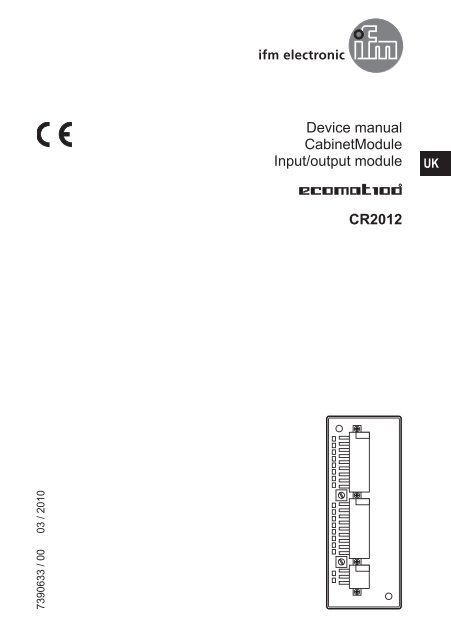
<strong>Device</strong> <strong>manual</strong><br />
<strong>CabinetModule</strong><br />
<strong>Input</strong>/<strong>output</strong> <strong>module</strong><br />
UK<br />
CR2012<br />
7390633 / 00 03 / 2010
<strong>CabinetModule</strong> CR2012<br />
Contents<br />
1 Safety instructions 3<br />
1.1 Notes on this <strong>manual</strong> 3<br />
1.2 Notes on the device 3<br />
2 Functions and features 4<br />
2.1 CAN communication 4<br />
3 Mounting 5<br />
3.1 Mounting location 5<br />
3.2 Fixing 5<br />
3.3 Cooling 5<br />
4 Electrical connection 6<br />
4.1 Connectors 6<br />
4.2 Fuses 6<br />
5 Set-up 7<br />
5.1 CoDeSys PLC configuration 7<br />
5.2 <strong>Electronic</strong> data sheet 7<br />
6 Parameter setting 8<br />
6.1 Automatic saving 8<br />
6.2 Restoring the factory setting 8<br />
6.3 Communication profiles; Idx 1000 to 1FFF 9<br />
6.4 Manufacturer-specific profiles; Idx 2000 to 6FFF 10<br />
6.5 EMCY objects 11<br />
6.6 Boot-up message 11<br />
7 Technical data 12<br />
7.1 Dimensions, mechanics, electronics 12<br />
7.2 Connecting, operating and display elements 13<br />
7.3 Characteristics of the inputs/<strong>output</strong>s, test standards and regulations 14<br />
7.4 Wiring 15<br />
8 Maintenance, repair and disposal 16<br />
9 Approvals/standards 16<br />
10 Terms and abbreviations 17<br />
11 Anhang / Appendix<br />
Objektverzeichnis / Object directory 19<br />
11.1 Communication profiles; Idx 1000 to 1FFF 19<br />
11.2 Manufacturer-specific profiles; Idx 2000 to 6FFF 24<br />
This device <strong>manual</strong> applies to devices as from the production status CR2012AE<br />
2
<strong>CabinetModule</strong> CR2012<br />
1<br />
Safety instructions<br />
1.1<br />
Notes on this <strong>manual</strong><br />
This <strong>manual</strong> is part of the device. It contains information and illustrations<br />
about the correct handling of the device and must be read before installation<br />
or use.<br />
Observe the operating instructions. Non-observance of the notes, operation which<br />
is not in accordance with the intended use, wrong installation or handling can<br />
result in serious harm concerning the safety of persons and plant.<br />
These instructions are intended for “authorised” persons according to the EMC<br />
and low-voltage directives.<br />
UK<br />
1.2 Notes on the device<br />
The device must only be installed, connected and put into operation by a qualified<br />
electrician.<br />
Disconnect the device externally before handling it. If necessary, also disconnect<br />
any independently supplied <strong>output</strong> load circuits.<br />
If the device is not supplied by the mobile on-board system (12/24 V battery<br />
operation), it must be ensured that the external voltage is generated and supplied<br />
according to the criteria for safety extra-low voltage (SELV) as this voltage is supplied<br />
without further measures to the connected controller, the sensors and the<br />
actuators.<br />
The wiring of all signals in connection with the SELV circuit of the device must also<br />
comply with the SELV criteria (safety extra-low voltage, safe electrical separation<br />
from other electric circuits). If the supplied SELV voltage is externally grounded<br />
(SELV becomes PELV), the responsibility lies with the user and the respective national<br />
installation regulations must be complied with. All statements in this <strong>manual</strong><br />
refer to the device the SELV voltage of which is not grounded.<br />
The connection terminals may only be supplied with the signals indicated in the<br />
technical data and/or on the device label and only the approved accessories of ifm<br />
electronic may be connected.<br />
According to the technical specifications below the device can be operated in a<br />
wide operating temperature range. Because of the additional internal heating the<br />
housing walls can have high perceptible temperatures when touched in hot environments.<br />
In case of malfunctions or uncertainties please contact the manufacturer. Tampering<br />
with the device can lead to serious risks for the safety of persons and plant. It<br />
is not permitted and leads to the exclusion of any liability and warranty claims.<br />
3
<strong>CabinetModule</strong> CR2012<br />
2<br />
Functions and features<br />
The device enables decentralised evaluation of sensor signals and decentralised<br />
triggering of actuators and proportional valves.<br />
WARNING<br />
The device is not approved for safety tasks with respect to the protection of persons.<br />
2.1 CAN communication<br />
●● The device supports binary/analogue inputs/<strong>output</strong>s and is therefore classified<br />
in the device class “I/O <strong>module</strong>” to CiA DS 401.<br />
●● As regards the input/<strong>output</strong> functions, the device can be configured and it supports<br />
the following functions:<br />
–– analogue inputs<br />
–– binary inputs<br />
–– binary <strong>output</strong>s<br />
–– PWM <strong>output</strong>s<br />
●● There are 1 server SDO and 4 default PDOs according to CiA DS 401.The<br />
PDO mapping can be changed (dynamic PDO mapping).<br />
The default identifiers are assigned according to the “predefined connection<br />
set”.<br />
●● The COB IDs of the PDOs as well as the transmission type (synch/asynch) of<br />
the individual PDOs can be configured.<br />
●● The device expects a synch object. The CAN identifier of the synch object can<br />
be configured.<br />
●● The device supports “node guarding” and “heartbeat”. The “guard time”, the<br />
“life time factor” and the “heartbeat time” can be configured.<br />
●● The device generates an emergency object. The COB ID of the EMCY object<br />
can be configured.<br />
●● The device stores the last error. The error code of the corresponding emergency<br />
object is stored.<br />
●● The device supports a reset function, i.e. the assignment of the parameters to<br />
the factory default settings on request.<br />
Factory default settings → 6.3 Communication profiles and 6.4 Manufacturerspecific<br />
profiles<br />
4
<strong>CabinetModule</strong> CR2012<br />
3<br />
Mounting<br />
3.1 Mounting location<br />
►► The device is to be mounted in a dry and enclosed environment (e.g. control<br />
panel of the driver‘s cab, separate control boxes, etc.).<br />
ATTENTION<br />
The housing must not be exposed to any torsion forces or mechanical stress.<br />
UK<br />
3.2 Fixing<br />
►► Fix the device using 2 M4 x L screws via transversely arranged bore holes.<br />
Tighten the screws alternately crosswise.<br />
–– Tightening torque: 1.5 Nm<br />
–– Mounting position: as required<br />
–– Hole dimensions: → 7.1 Dimensions, mechanics, electronics<br />
3.3 Cooling<br />
►► As the internal heating of the electronics is conducted away via the housing,<br />
ensure sufficient heat dissipation.<br />
5
<strong>CabinetModule</strong> CR2012<br />
4<br />
Electrical connection<br />
4.1<br />
Connectors<br />
The supply cables and inputs/<strong>output</strong>s are connected via AMP crimp connectors on<br />
the front of the device.<br />
<br />
<br />
<br />
<br />
<br />
<br />
<br />
<br />
<br />
<br />
<br />
<br />
<br />
<br />
<br />
<br />
<br />
<br />
<br />
<br />
<br />
<br />
<br />
<br />
<br />
Pin connection → 7 Technical data → 7.4 Wiring<br />
You can find more information about the available connector accessories at:<br />
www.ifm-electronic.com → Data sheet direct → CR2012 → Accessories<br />
4.2<br />
Fuses<br />
►► To protect the whole system (wiring and device) the individual electric circuits<br />
must be protected with max. 8 A.<br />
6
<strong>CabinetModule</strong> CR2012<br />
5<br />
Set-up<br />
5.1<br />
CoDeSys PLC configuration<br />
Parameter setting of the device functions and of the CAN interface is directly done<br />
from the application programmed with CoDeSys 2.3. To do so, the “<strong>Electronic</strong> Data<br />
Sheet” (EDS) is integrated via the CoDeSys PLC configuration.<br />
UK<br />
CoDeSys dialogue “control and CANopen configuration” (example)<br />
For a description of the setting and application of the “PLC and CANopen configuration”<br />
dialogue see the CoDeSys <strong>manual</strong> and the CoDeSys online help.<br />
5.2 <strong>Electronic</strong> data sheet<br />
The EDS contains the description of all parameters and I/O data of the device in<br />
a format defined by CANopen. The EDS files are provided by ifm electronic for all<br />
CANopen slaves.<br />
The EDS files are available at:<br />
www.ifm-electronic.com → Data sheet direct → CR2012 → Download/Software*<br />
*) Downloads with registration<br />
7
<strong>CabinetModule</strong> CR2012<br />
6<br />
Parameter setting<br />
6.1<br />
Automatic saving<br />
Automatic saving of the communication and device parameters can be activated or<br />
deactivated by means of the “save parameter” entry (object directory, index 1010,<br />
S-Idx 01).<br />
● Value 0x00:<br />
There is no automatic saving. Changed parameters are only valid until the device<br />
is switched off or until the next reset.<br />
● Value 0x01:<br />
Changed parameters will be saved if the string “save” is written in S-Idx 01. Otherwise<br />
changed parameters are only valid until the device is switched off or until the<br />
next reset.<br />
● Value 0x02:<br />
Changed parameters are saved automatically.<br />
6.2 Restoring the factory setting<br />
With the function “restore” (object directory, index 1011, subindex 01) the factory<br />
default values can be restored (except for the baud rate and the node ID). They<br />
become valid with the next power on.<br />
8
<strong>CabinetModule</strong> CR2012<br />
6.3<br />
Communication profiles; Idx 1000 to 1FFF<br />
Parameters<br />
Index in<br />
object<br />
directory<br />
Default value (factory<br />
preset)<br />
Change saved<br />
automatically<br />
Change<br />
effective<br />
COB ID Synch Object 1005 00 0x80 adjustable after PreOp<br />
Communication Cycle 1006 00 0x00 (Off) adjustable immediately<br />
Guard Time 100C 00 0x00 (Off) adjustable immediately<br />
Life Time Factor 100D 00 0x00 adjustable immediately<br />
Save Parameter 1010 01 0x02 (AutoSave ON) yes immediately<br />
COB-ID EMCY 1014 00 0x80 + node ID adjustable after a reset<br />
Consumer Heartbeat Time 1016 01 0x00 (Off) adjustable immediately<br />
Producer Heartbeat Time 1017 00 0x00 (Off) adjustable immediately<br />
COB-ID Rx PDO 1 1400 01 0x200 + node ID adjustable after PreOp<br />
Trans Type Rx PDO 1 1400 02 0x01 (synchronous) adjustable immediately<br />
COB-ID Rx PDO 2 1401 01 0x300 + node ID adjustable after PreOp<br />
Trans Type Rx PDO 2 1401 02 0x01 (synchronous) adjustable immediately<br />
COB-ID Tx PDO 1 1800 01 0x180 + node ID adjustable after PreOp<br />
Trans Type Tx PDO 1 1800 02 0xFF (asynchronous) adjustable immediately<br />
Inhibit Timer Tx PDO 1 1800 03 0x0000 adjustable immediately<br />
Event Timer Tx PDO 1 1800 05 0x00 adjustable immediately<br />
COB-ID Tx PDO 2 1801 01 0x280 + node ID adjustable after PreOp<br />
Trans Type Tx PDO 2 1801 02 0x01 (synchronous) adjustable immediately<br />
Inhibit Timer Tx PDO 2 1801 03 0x0000 adjustable immediately<br />
Event Timer Tx PDO 2 1801 05 0x00 adjustable immediately<br />
UK<br />
The life time factor 0 is interpreted as 1.The first guard protocol is interpreted as<br />
"start guarding” even if guarding is not yet active at that time (guard time = 0).<br />
Abbreviations → 10 Terms and abbreviations<br />
9
<strong>CabinetModule</strong> CR2012<br />
6.4<br />
Manufacturer-specific profiles; Idx 2000 to 6FFF<br />
Parameters<br />
Index in object<br />
directory<br />
Default value<br />
(factory preset)<br />
Config. channel 1 2000 01 0x01 (Bin IN)<br />
Config. channel 2 2000 02 0x01 (Bin IN)<br />
Config. channel 3 2000 03 0x01 (Bin IN)<br />
Config. channel 4 2000 04 0x01 (Bin IN)<br />
Config. channel 5 2000 05 0x03 (Ana IN absolute)<br />
Config. channel 6 2000 06 0x03 (Ana IN absolute)<br />
Config. channel 7 2000 07 0x02 (Bin OUT + read<br />
back input)<br />
Config. channel 8 2000 08 0x02 (Bin OUT + read<br />
back input)<br />
Config. channel 9 2000 09 0x01 (Bin IN)<br />
Config. channel 10 2000 0A 0x01 (Bin IN)<br />
Config. channel 11 2000 0B 0x01 (Bin IN)<br />
Config. channel 12 2000 0C 0x01 (Bin IN)<br />
Config. channel 13 2000 0D 0x03 (Ana IN absolute)<br />
Config. channel 14 2000 0E 0x03 (Ana IN absolute)<br />
Config. channel 15 2000 0F 0x02 (Bin OUT + read<br />
back input)<br />
Config. channel 16 2000 10 0x02 (Bin OUT + read<br />
back input)<br />
Change saved<br />
automatically<br />
Change<br />
effective<br />
adjustable after PreOp<br />
PWM frequency 2001 00 0x64 (100 Hz) adjustable after PreOp<br />
Node ID * 20F0, 20F1 0x20 (0d32) yes after a reset<br />
Baud rate * 20F2, 20F3 0x04 (125 Kbit/s) yes after a reset<br />
Autostart 20F4 0x00 (Off) adjustable immediately<br />
*) Observe rotary switch position!<br />
Entries in the object directory indexes 20F0/20F1 and/or 20F2/20F3 are only valid<br />
if the rotary switches for baud rate and/or node ID are in the position “F”.<br />
Position and coding of the rotary switches → 7 Technical data<br />
10
<strong>CabinetModule</strong> CR2012<br />
6.5<br />
EMCY objects<br />
The following error codes are supported according to DSP-301 and DSP-401:<br />
EMCY code Error reg Additional<br />
code<br />
Description<br />
0x6100 0x11 0x00 "Internal Software":<br />
overflow of an Rx queue; e.g. frequency of the Rx PDOs<br />
too high<br />
only external reset via an entry in 1003 00<br />
0x6101 0x11 0x00 "Internal Software":<br />
overflow of a Tx queue; e.g. device does not<br />
communicate with the bus<br />
only external reset via an entry in 1003 00<br />
0x8100 0x11 0x00 "Monitoring" (guarding error)<br />
no guard object is received for "guard time" x "life time<br />
factor"<br />
reset with the next communication<br />
0x8120 0x11 0x00 "Communication" (CAN error passive)<br />
CAN controller has passed into the CAN error passive<br />
state<br />
0x8200 0x11 0x00 "Monitoring" (synch error)<br />
for "communication cycle" no synch object is received;<br />
only in OPERATIONAL<br />
reset with the next synch OBJ or PREOP<br />
UK<br />
6.6 Boot-up message<br />
The <strong>module</strong> sends a boot-up message after application of the supply voltage or<br />
after a reset, to inform a CANopen master in the network about its presence or a<br />
restart.<br />
To ensure the compatibility with older device versions, a boot-up message is sent<br />
in accordance with CANopen specifications DS-301 V3 and V4.<br />
11
<strong>CabinetModule</strong> CR2012<br />
7<br />
Technical data<br />
7.1<br />
Control systems<br />
Dimensions, mechanics, electronics<br />
CR2012<br />
<strong>CabinetModule</strong><br />
<br />
<br />
I/O <strong>module</strong><br />
digital and analogue<br />
for R 360 system<br />
<br />
<br />
<br />
16 inputs/<strong>output</strong>s<br />
<br />
<br />
CANopen interface<br />
<br />
10...32 V DC<br />
<br />
Application<br />
Structure<br />
Dimensions (l x w x h)<br />
Installation<br />
Protection<br />
Possible I/O-configurations<br />
(also see wiring)<br />
<strong>Input</strong>s, digital<br />
<strong>Input</strong>s, analogue<br />
(to be configured via CANopen)<br />
Outputs<br />
Connection of operating and display elements to CAN bus<br />
to be installed in driver’s cabs, control panels or control boxes<br />
PCB without housing<br />
(for mechanical protection potted in a potting tub)<br />
163 x 63 x 26.7 mm<br />
via 2 transversely arranged bore holes<br />
IP00 (PCB without housing), to EN60529<br />
8 digital inputs<br />
4 digital/analogue inputs (to be configured via CANopen)<br />
2 digital inputs/<strong>output</strong>s (to be configured via CANopen)<br />
2 digital inputs/<strong>output</strong>s, analogue <strong>output</strong>s (to be configured via CANopen)<br />
for positive-switching sensor signals, switches or pushbuttons<br />
• ratiometric, query of potentiometric signal transmitters (e.g. joystick)<br />
• absolute, conversion of input voltage (0...10 V) in 8-bit value<br />
for triggering pilot lights etc.<br />
\DATEN\100\DB-FORM—PZD/03/12/96<br />
Connections<br />
<strong>Input</strong>s/<strong>output</strong>s<br />
Operating voltage and CAN bus<br />
Operating voltage U B<br />
12<br />
AMP crimp connector, to be clipped into place and thus vibration-resistant,<br />
protected against reverse polarity<br />
2 plugs, 18 poles<br />
1 plug, 6 poles<br />
10...32 V DC<br />
Current consumption ≤ 100 mA, without load (external fuse with max. 5 A)<br />
Operating/storage temperature<br />
Controller<br />
-40...+85°C / -40...+85°C<br />
16 bits Fujitsu MB90F543<br />
Interface CAN interface 2.0 B, ISO 11898<br />
Baud rate<br />
Controller<br />
20 Kbits/s...1 Mbit/s (default setting 125 Kbits/s)<br />
adjustable via rotary switches or CANopen object directory<br />
16 bits Fujitsu MB90F543<br />
Communication profile CANopen, CiA DS 301 version 4, CiA DS 401 version 2.1<br />
Programming system<br />
from CoDeSys 2.3 via EDS<br />
Node ID (default) hex 20 (= dec 32)<br />
adjustable via rotary switch (1...14) or CANopen object directory (1...127)<br />
Status LED<br />
Accessories<br />
(to be ordered separately)<br />
CANopen: 2 LEDs (green, red)<br />
<strong>Input</strong>s/<strong>output</strong>s: 16 LEDs (yellow)<br />
Order no. EC2053<br />
Plug set for <strong>CabinetModule</strong>s, wirable, consisting of:<br />
AMP crimp housing, 1 x 6 poles, 2x18 poles<br />
incl. crimp contacts (Junior Power Timer)<br />
ifm electronic gmbh • Friedrichstraße 1 • 45128 Essen We reserve the right to make technical alterations without prior notice! CR2012 / page 1 17.03.2010
8<br />
4<br />
<strong>CabinetModule</strong> CR2012<br />
7.2<br />
Connecting,<br />
Control systemsoperating and display elements<br />
CR2012<br />
Technical data<br />
Operating and indicating elements<br />
Connector<br />
Rotary switch<br />
hex-coded <br />
S1 <br />
S2 <br />
Baud rate Node ID<br />
<br />
<br />
<br />
<br />
<br />
AMP<br />
Crimp connector<br />
UK<br />
Hex-code switch coding<br />
Switch Position Description<br />
S1 0 1000 Kbits/s<br />
Baud rate 1 800 kBits/s<br />
2 500 Kbit/s<br />
3 250 Kbit/s<br />
4 125 Kbit/s<br />
5 100 Kbit/s<br />
6 50 Kbit/s<br />
7 20 Kbit/s<br />
8...E not defined<br />
F adjustment via object directory (default)<br />
S2 0 not defined<br />
Node-ID 1...E 1...14<br />
F adjustment via object directory (default)<br />
•<br />
E<br />
•<br />
C<br />
A<br />
•<br />
•<br />
0<br />
•<br />
•<br />
2<br />
•<br />
•<br />
6<br />
Operating states (LEDs)<br />
LED State Description<br />
PWR (green) OFF no supply voltage<br />
ON<br />
<strong>module</strong> in stand-by mode<br />
CANopen status: PREOPERATIONAL / PREPARED<br />
<strong>output</strong>s = OFF<br />
1 x ON <strong>module</strong> in stop mode<br />
CANopen status: STOP<br />
<strong>output</strong>s = OFF<br />
2.5 Hz <strong>module</strong> active<br />
CANopen status: OPERATIONAL<br />
<strong>output</strong>s are updated<br />
DIA (red) OFF communication OK<br />
ON communication disturbed, CAN bus OFF<br />
1 x ON communication disturbed:<br />
• CAN error warning level exceeded<br />
2 x ON • node guard / heartbeat error<br />
(if node guarding / heartbeat is activated)<br />
3 x ON • no synch objects<br />
(if synch monitoring is activated)<br />
IN (yellow) OFF input not switched<br />
ON input switched<br />
OUT (yellow) OFF binary <strong>output</strong> not switched (OFF)<br />
analogue <strong>output</strong>:<br />
PWM preset value < 1% measuring range<br />
ON binary <strong>output</strong> switched (ON)<br />
analogue <strong>output</strong>:<br />
PWM preset value > 2% measuring range<br />
ifm electronic gmbh • Friedrichstraße 1 • 45128 Essen We reserve the right to make technical alterations without prior notice! CR2012 / page 2 17.03.2010<br />
13
<strong>CabinetModule</strong> CR2012<br />
Control systems<br />
7.3 Characteristics of the inputs/<strong>output</strong>s, test standards and regulations<br />
CR2012<br />
<strong>Input</strong>s<br />
Channels 1...4, channels 9...12<br />
Channels 7...8, channels 15...16<br />
Channels 5...6, channels 13...14<br />
Outputs<br />
Channels 7, 15<br />
Channels 8, 16<br />
Characteristics of the inputs / <strong>output</strong>s<br />
• 8 inputs for positive sensor signals<br />
For each input the pins +U B and Bin INx are available<br />
• 4 inputs for positive sensor signals<br />
Can be used as an alternative to the 4 <strong>output</strong>s.<br />
For input and <strong>output</strong> one pin is available (double configuration).<br />
The inputs can be used to read back the <strong>output</strong> signals.<br />
Current consumption I IN = 4 mA (for U B = 10 V)<br />
I IN = 17 mA (for U B = 30 V)<br />
Switching threshholds HIGH = 8 V LOW = 2.5 V<br />
Switching frequency 25 Hz max. (for ti = tp)<br />
• 4 inputs, to be configured via CANopen:<br />
for ratiometric measurement for potentiometric transducers (e.g. joystick)<br />
For each input the pins +U B , Ana INx and GND are available<br />
<strong>Input</strong> resistance<br />
typ. 50 kΩ<br />
Resolution based on 1/2 supply voltage U B<br />
= ± 200 steps (for U B = 12 V), ± 400 steps (for U B = 24 V)<br />
for absolute value measurement 0...10 V<br />
For each input the pins Ana INx and GND are available<br />
<strong>Input</strong> resistance<br />
typ. 50 kΩ<br />
Resolution<br />
8 bits<br />
Accuracy<br />
typ. ± 2 LSB<br />
as binary inputs<br />
For each input the pins +U B and Bin INx are available<br />
<strong>Input</strong> resistance<br />
typ. 50 kΩ<br />
Switching threshhold at 1/2 supply voltage U B<br />
• 2 positive-switching <strong>output</strong>s; short-circuit and overload protected;<br />
the supply voltage U B is switched without additional fuse.<br />
The <strong>output</strong> states can be read back (see inputs).<br />
For each input the pins Bin OUTx and GND are available.<br />
When inductive loads are switched, free-wheeling diodes must be connected in<br />
parallel with the load!<br />
Switching current<br />
max. 500 mA<br />
• 2 PWM <strong>output</strong>s (high side), variable frequency<br />
PWM frequency<br />
20...250 Hz<br />
Pulse duty factor 0...1000 ‰<br />
Resolution 1 ‰<br />
Switching current<br />
max. 500 mA<br />
Test standards and regulations<br />
Immunity to<br />
conducted interference<br />
Immunity to interfering fields<br />
Interference emission<br />
to ISO 7637-2, pulses 2a, 3a, 3b, 4, severity level 4, function state A<br />
to ISO 7637-2, pulse 5, severity level 3, function state A<br />
to ISO 7637-2, pulse 1, 2b, severity level 4, function state C<br />
to directive 06/28/EC at 100V/m (e1 type approval)<br />
and EN 61000-6-2: 2005 (CE)<br />
to directive 06/28/EC (e1 type approval)<br />
and EN 61000-6-3: 2007 (CE)<br />
\DATEN\100\DB-FORM—PZD/03/12/96<br />
ifm electronic gmbh • Friedrichstraße 1 • 45128 Essen We reserve the right to make technical alterations without prior notice! CR2012 / page 3 17.03.2010<br />
14
<strong>CabinetModule</strong> CR2012<br />
Control systems<br />
7.4 Wiring<br />
CR2012<br />
Wiring<br />
View of the unit<br />
<br />
<br />
<br />
<br />
<br />
<br />
<br />
<br />
<br />
<br />
<br />
<br />
<br />
<br />
<br />
<br />
<br />
<br />
<br />
<br />
<br />
<br />
<br />
<br />
<br />
UK<br />
Wiring<br />
Plug X1<br />
Pin Potential <strong>Input</strong>s Outputs<br />
1 channel 1 Bin IN 1 – – –<br />
2 +U B<br />
3 channel 2 Bin IN 2 – – –<br />
4 +U B<br />
5 channel 3 Bin IN 3 – – –<br />
6 +U B<br />
7 channel 4 Bin IN 4 – – –<br />
8 +U B<br />
9 +U B<br />
10 +U B<br />
11 channel 5 Bin IN 5 Ana IN 5 – –<br />
12 channel 6 Bin IN 6 Ana IN 6 – –<br />
13 GND<br />
14 GND<br />
15 channel 7 Bin IN 7 – Bin OUT 7<br />
16 GND<br />
17 channel 8 Bin IN 8 – Bin OUT 8 PWM 8<br />
18 GND<br />
Plug X2<br />
1 channel 9 Bin IN 9 – – –<br />
2 +U B<br />
3 channel 10 Bin IN 10 – – –<br />
4 +U B<br />
5 channel 11 Bin IN 11 – – –<br />
6 +U B<br />
7 channel 12 Bin IN 12 – – –<br />
8 +U B<br />
9 +U B<br />
10 +U B<br />
11 channel 13 Bin IN 13 Ana IN 13 – –<br />
12 channel 14 Bin IN 14 Ana IN 14 – –<br />
13 GND<br />
14 GND<br />
15 channel 15 Bin IN 15 – Bin OUT 15<br />
16 GND<br />
17 channel 16 Bin IN 16 – Bin OUT 16 PWM 16<br />
18 GND<br />
Plug X3<br />
\DATEN\100\DB-FORM—PZD/03/12/96<br />
1 +U B<br />
2 GND<br />
3 +U B<br />
4 GND<br />
5 CAN_L<br />
6 CAN_H<br />
ifm electronic gmbh • Friedrichstraße 1 • 45128 Essen We reserve the right to make technical alterations without prior notice! CR2012 / page 4 17.03.2010<br />
15
<strong>CabinetModule</strong> CR2012<br />
8<br />
Maintenance, repair and disposal<br />
►► Do not open the housing, as the device does not contain any components<br />
which must be maintained by the user. The device must only be repaired by the<br />
manufacturer.<br />
►► Dispose of the device in accordance with the national environmental regulations.<br />
9<br />
Approvals/standards<br />
Test standards and regulations → 7 Technical data<br />
The CE Declaration of Conformity and the e1 approval are available at:<br />
www.ifm-electronic.com → Data sheet direct → CR2012 → Approvals<br />
16
<strong>CabinetModule</strong> CR2012<br />
10<br />
Terms and abbreviations<br />
0b ... binary value (for bit coding), e.g. 0b0001 0000<br />
0d ...<br />
decimal value, e.g. 0d100<br />
0x ...<br />
hexadecimal value, e.g. 0x64 (= 100 decimal)<br />
Baud rate<br />
transmission speed (1 baud = 1 bit/s)<br />
CAL<br />
CAN application layer<br />
CAN-based network protocol on application level<br />
CAN<br />
controller area network (bus system for the use in mobile vehicles)<br />
CAN_H<br />
CAN high; CAN connection/cable with high voltage level<br />
CAN_L<br />
CAN low; CAN connection/cable with low voltage level<br />
CANopen<br />
CAN-based network protocol on application level with an open configuration interface<br />
(object directory).<br />
CiA<br />
“CAN in Automation e.V.”(user and manufacturer organisation in Germany/Erlangen)<br />
definition and control body for CAN and CAN-based network protocols<br />
CiA DS<br />
draft standard (published CiA specification which usually has not been modified or<br />
supplemented for one year)<br />
CiA DSP<br />
draft standard proposal (published CiA specification draft)<br />
CiA WD<br />
work draft (work draft accepted for discussion within CiA)<br />
CiA DS 301<br />
specification for CANopen communication profile;describes the basic communication<br />
between network participants such as the transfer of process data in real time, the<br />
exchange of data between devices or the configuration stage<br />
supplemented by the following CiA specifications depending on the application:<br />
CiA DS 401<br />
device profile for digital and analogue I/O <strong>module</strong>s<br />
CiA DS 402<br />
device profile for drives<br />
CiA DS 403<br />
device profile for HMI<br />
CiA DS 404<br />
device profile for measurement and control technology<br />
CiA DS 405 specification for interfaces to programmable systems (IEC 61131-3)<br />
CiA DS 406<br />
device profile for encoders<br />
CiA DS 407<br />
application profile for local public transport<br />
COB CANopen communication object (PDO, SDO, EMCY, ...)<br />
COB-ID<br />
CANopen identifier of a communication object<br />
Communication cycle the synchronisation time to be monitored; max. time between 2 synch objects<br />
EMCY object emergency object (alarm message; device indicates an error)<br />
Error Reg<br />
error register (entry with an error code)<br />
Guarding Error node or network participant could or can no longer be found<br />
guard MASTER: one or several SLAVES no longer reply<br />
guard SLAVE: no polling of the device (SLAVE)<br />
Guard Time<br />
during this time the network participant expects a “node guarding” of the network<br />
master<br />
Heartbeat<br />
cyclic monitoring with parameter setting among network participants<br />
In contrast to “node guarding” no superior NMT master is required.<br />
ID (also identifier) identifier; identifies a CAN message; the numerical value of the ID also contains a<br />
priority for the access to the bus systemID 0 = top priority.<br />
Idx<br />
index; together with the subindex it forms the address of an entry in the object directory<br />
Life Time Factor number of attempts in case of a missing guarding reply<br />
Monitoring<br />
is used to describe the error class (guarding monitoring, synch etc.)<br />
NMT<br />
network management<br />
NMT master/slaves the NMT master controls the operating states of the NMT slaves<br />
Node Guarding adjustable cyclical monitoring of slave network participants by a higher master node<br />
as well as monitoring of this polling process by the slave participants<br />
Node ID<br />
node identifier (identification of a participant in the CANopen network)<br />
Object (also OBJ) term for data/messages which can be exchanged in the CANopen network<br />
Object directory contains all CANopen communication parameters of a device as well as device-specific<br />
parameters and data;<br />
access to the individual entries is possible via the index and subindex<br />
UK<br />
17
<strong>CabinetModule</strong> CR2012<br />
Operational<br />
PDO<br />
PDO Mapping<br />
Pre-Op<br />
Prepared<br />
Rec PDO<br />
(also Rx PDO)<br />
ro<br />
rw<br />
Rx-Queue<br />
s16<br />
SDO<br />
Server SDO<br />
S-Idx (also SIdx)<br />
Start Guarding<br />
str<br />
Sync Error<br />
Sync OBJ<br />
Sync Windows<br />
Time Stamp<br />
Trans Type<br />
Trans PDO<br />
(also Tx PDO)<br />
Trans SDO<br />
(also Tx SDO)<br />
Tx-Queue<br />
u8 (16, 32)<br />
wo<br />
operating state of a CANopen participant in this mode SDOs, NMT commands and<br />
PDOs can be transferred<br />
process data object; in the CANopen network for transfer of process data in real time<br />
such as the speed of a motor<br />
PDOs have a higher priority than SDOs; in contrast to the SDOs they are transferred<br />
without confirmation; PDOs consist of a CAN message with identifier and up to 8<br />
bytes of user data.<br />
describes the application data transferred with a PDO<br />
preoperational; operating state of a CANopen participant;<br />
after application of the supply voltage each participant automatically goes into this<br />
state;<br />
in the CANopen network only SDOs and NMT commands can be transferred in this<br />
mode but no process data<br />
(also stopped) operating state of a CANopen participant<br />
in this mode only NMT commands are transferred<br />
(receive) process data object<br />
read only (unidirectional)<br />
read-write (bidirectional)<br />
receive buffer<br />
data type signed 16 bits (incl. sign, 16-bit format)<br />
service data object;<br />
with this object direct access to the object directory of a network participant is possible<br />
(read/write); an SDO can consist of several CAN messages; the transfer of the<br />
individual messages is confirmed by the addressed participant<br />
with the SDOs devices can be configured and parameters can be set<br />
process and parameter set to make the object directory of a network participant available<br />
to other participants (clients)<br />
subindex within the object directory of a CANopen device<br />
start node guarding<br />
data type string (variable for strings such as text “load”)<br />
missing synch object OBJ in the adjustable synchronisation time<br />
synchronisation object for simultaneous update in the complete network or for accepting<br />
process data of the respective parameterised PDOs<br />
time during which the synchronous PDOs have to be transferred<br />
time stamp to align existing clocks in network participants<br />
type of process data transmission; synchronous, asynchronous<br />
transmit process data object<br />
transmit service data object<br />
transmit buffer<br />
data type unsigned 8 (16, 32) bits (unsigned, 8 (16, 32) bit format)<br />
write only<br />
18
<strong>CabinetModule</strong> CR2012<br />
11 Anhang / Appendix<br />
Objektverzeichnis / Object directory<br />
11.1<br />
Communication profiles; Idx 1000 to 1FFF<br />
Index S-Idx Name Type Default Description<br />
1000 0 device type ro u32 0x000F0191 I/O-<strong>module</strong> profile DS401<br />
digital/analogue inputs/<strong>output</strong>s<br />
1001 0 error register ro u8 0x00<br />
1003 0 pre-definded error field rw u8 0x00 up to 4 entries in error history<br />
supported<br />
error history can be deleted by<br />
writing '0' to this entry<br />
1 error history ro u32 0x00000000<br />
2 error history ro u32 0x00000000<br />
3 error history ro u32 0x00000000<br />
4 error history ro u32 0x00000000<br />
1005 0 COB ID SYNC rw u32 0x00000080<br />
1006 0 communication cycle<br />
period<br />
1008 0 device name ro str CR2012<br />
1009 0 HW Version ro str HW Vx.x<br />
100A 0 SW Version ro str SW Vx.x<br />
rw u32 0x00000000 max. time between 2 synch<br />
objects in µs; useful resolution<br />
= 1 ms<br />
100C 0 guard time rw u16 0x0000 time in ms<br />
within this time the <strong>module</strong><br />
expects a "node guarding" of the<br />
network master<br />
0 = node guarding deactivated<br />
100D 0 life time factor rw u8 0x00 if no "node guarding" is received<br />
for "guard time" x "life time", the<br />
<strong>module</strong> generates an EMCY<br />
the result form "guard time" x "life<br />
time" must be between 0 and<br />
65535<br />
1010 0 number of save<br />
options<br />
ro u8 0x01<br />
1 save parameter rw u32 0x00000002 0x00000000 = no save<br />
0x00000001 = saving all<br />
parameters after the string 'save'<br />
is written to this entry<br />
0x00000002 = auto save<br />
1011 0 number of restore<br />
options<br />
1 restore default<br />
parameter<br />
ro u8 0x01<br />
rw u32 0x00000001 restore all parameters to default<br />
value after next reset if the string<br />
'load' is written to this entry<br />
UK<br />
19
<strong>CabinetModule</strong> CR2012<br />
Index S-Idx Name Type Default Description<br />
1014 0 COB ID EMCY rw u32 0x40000080<br />
+ NodeID<br />
1016 0 number of monitored<br />
devices<br />
1 consumer heartbeat<br />
time<br />
1017 0 producer heartbeat<br />
time<br />
1018 0 number of identity<br />
objects<br />
ro u8 0x01<br />
<strong>module</strong> generates EMCY<br />
messages<br />
(bit 30 = 1)<br />
rw u32 0x00000000 heartbeat monitoring time for<br />
node n<br />
monitoring of only one node is<br />
supported<br />
0x0nntttt = monitoring time [ms]<br />
0x0nntttt = node number<br />
(if nn or tttt = 0, no monitoring is<br />
carried out)<br />
rw u16 0x0000 time interval [ms] where the<br />
<strong>module</strong> generates a producer<br />
heartbeat<br />
ro u8 0x04<br />
1 vendor ID ro u32 0x0069666D<br />
1400 0 highest numbered<br />
subindex Receive<br />
PDO 1<br />
1 COB ID Receive<br />
PDO 1<br />
2 transmission type Rec<br />
PDO 1<br />
1401 0 highest numbered<br />
subindex Receive<br />
PDO 2<br />
1 COB ID Receive<br />
PDO 2<br />
2 transmission type Rec<br />
PDO 2<br />
1600 0 number of application<br />
objects linked with Rec<br />
PDO 1<br />
1 1st mapping object<br />
Rec PDO 1<br />
2 2nd mapping object<br />
Rec PDO 1<br />
3 3rd mapping object<br />
Rec PDO 1<br />
4 4th mapping object<br />
Rec PDO 1<br />
ro u8 0x02<br />
rw u32 0x00000200<br />
+ NodeID<br />
PDO is valid (bit 31 = 0)<br />
rw u8 0x01 0x01...0xF0 = synch cyclic<br />
0xFE...0xFF = asynch<br />
(immediately)<br />
ro u8 0x02<br />
rw u32 0x00000300<br />
+ NodeID<br />
PDO is valid (bit 31 = 0)<br />
rw u8 0x01 0x01...0xF0 = synch cyclic<br />
0xFE...0xFF = asynch<br />
(immediately)<br />
rw u8 0x01<br />
rw u32 0x08010062 index 6200, subindex 1, 8 bits<br />
rw u32 0x00000000 no object<br />
rw u32 0x00000000 no object<br />
rw u32 0x00000000 no object<br />
20
<strong>CabinetModule</strong> CR2012<br />
Index S-Idx Name Type Default Description<br />
5 5th mapping object<br />
Rec PDO 1<br />
6 6th mapping object<br />
Rec PDO 1<br />
7 7th mapping object<br />
Rec PDO 1<br />
8 8th mapping object<br />
Rec PDO 1<br />
1601 0 number of application<br />
objects linked with Rec<br />
PDO 2<br />
1 1st mapping object<br />
Rec PDO 2<br />
2 2nd mapping object<br />
Rec PDO 2<br />
3 3rd mapping object<br />
Rec PDO 2<br />
4 4th mapping object<br />
Rec PDO 2<br />
5 5th mapping object<br />
Rec PDO 2<br />
6 6th mapping object<br />
Rec PDO 2<br />
7 7th mapping object<br />
Rec PDO 2<br />
8 8th mapping object<br />
Rec PDO 2<br />
1800 0 highest numbered<br />
subindex Transmit<br />
PDO 1<br />
1 COB ID Transmit<br />
PDO 1<br />
2 transmission type<br />
Trans PDO 1<br />
3 inhibit timer Trans<br />
PDO 1<br />
5 event timer Trans<br />
PDO 1<br />
1801 0 highest numbered<br />
subindex Transmit<br />
PDO 2<br />
rw u32 0x00000000 no object<br />
rw u32 0x00000000 no object<br />
rw u32 0x00000000 no object<br />
rw u32 0x00000000 no object<br />
rw u8 0x02<br />
rw u32 0x10011464 index 6414 subindex 1, 16 bits<br />
rw u32 0x10021464 index 6414 subindex 2, 16 bits<br />
rw u32 0x00000000 no object<br />
rw u32 0x00000000 no object<br />
rw u32 0x00000000 no object<br />
rw u32 0x00000000 no object<br />
rw u32 0x00000000 no object<br />
rw u32 0x00000000 no object<br />
ro u8 0x05<br />
rw u32 0x00000180<br />
+ NodeID<br />
PDO is valid (bit 31 = 0)<br />
rw u8 0xFF 0x01...0xF0 = synch cyclic<br />
0xFE...0xFF = asynch<br />
(immediately)<br />
rw u16 0x0000 min. interval for transmission (in<br />
100 µs)<br />
rw u16 0x0000 max transfer break in trans type<br />
"asynch" (0...65535 ms)<br />
when this time has elapsed the<br />
PDO is transferred even if the<br />
appl. event has not occurred<br />
ro u8 0x05<br />
UK<br />
21
<strong>CabinetModule</strong> CR2012<br />
Index S-Idx Name Type Default Description<br />
1 COB ID Transmit<br />
PDO 2<br />
2 transmission type<br />
Trans PDO 2<br />
3 inhibit timer Trans<br />
PDO 2<br />
5 event timer Trans<br />
PDO 2<br />
1A00 0 number of application<br />
objects linked with<br />
Trans PDO 1<br />
1 1st mapping object<br />
Trans PDO 1<br />
2 2nd mapping object<br />
Trans PDO 1<br />
3 3rd mapping object<br />
Trans PDO 1<br />
4 4th mapping object<br />
Trans PDO 1<br />
5 5th mapping object<br />
Trans PDO 1<br />
6 6th mapping object<br />
Trans PDO 1<br />
7 7th mapping object<br />
Trans PDO 1<br />
8 8th mapping object<br />
Trans PDO 1<br />
1A01 0 number of application<br />
objects linked with<br />
Trans PDO 2<br />
1 1st mapping object<br />
Trans PDO 2<br />
2 2nd mapping object<br />
Trans PDO 2<br />
3 3rd mapping object<br />
Trans PDO 2<br />
4 4th mapping object<br />
Trans PDO 2<br />
5 5th mapping object<br />
Trans PDO 2<br />
rw u32 0x00000280<br />
+ NodeID<br />
PDO is valid (bit 31 = 0)<br />
rw u8 0x01 0x01...0xF0 = synch cyclic<br />
0xFE...0xFF = asynch<br />
(immediately)<br />
rw u16 0x0000 min. interval for transmission (in<br />
100 µs)<br />
rw u16 0x0000 max transfer break in trans type<br />
"asynch" (0...65535 ms)<br />
when this time has elapsed the<br />
PDO is transferred even if the<br />
appl. event has not occurred<br />
rw u8 0x01<br />
rw u32 0x10010061 index 6100, subindex 1, 16 bits<br />
rw u32 0x00000000 no object<br />
rw u32 0x00000000 no object<br />
rw u32 0x00000000 no object<br />
rw u32 0x00000000 no object<br />
rw u32 0x00000000 no object<br />
rw u32 0x00000000 no object<br />
rw u32 0x00000000 no object<br />
rw u8 0x04<br />
rw u32 0x10010164 index 6401, subindex 1, 16 bits<br />
rw u32 0x10020164 index 6401, subindex 2, 16 bits<br />
rw u32 0x10030164 index 6401, subindex 3, 16 bits<br />
rw u32 0x10040164 index 6401, subindex 4, 16 bits<br />
rw u32 0x00000000 no object<br />
22
<strong>CabinetModule</strong> CR2012<br />
Index S-Idx Name Type Default Description<br />
6 6th mapping object<br />
Trans PDO 2<br />
7 7th mapping object<br />
Trans PDO 2<br />
8 8th mapping object<br />
Trans PDO 2<br />
rw u32 0x00000000 no object<br />
rw u32 0x00000000 no object<br />
rw u32 0x00000000 no object<br />
UK<br />
23
<strong>CabinetModule</strong> CR2012<br />
11.2<br />
Manufacturer-specific profiles; Idx 2000 to 6FFF<br />
Index S-Idx Name Type Default Description<br />
2000 0 number of IOs ro u8 0x10<br />
1 configuration channel<br />
1<br />
2 configuration channel<br />
2<br />
3 configuration channel<br />
3<br />
4 configuration channel<br />
4<br />
5 configuration channel<br />
5<br />
6 configuration channel<br />
6<br />
7 configuration channel<br />
7<br />
8 configuration channel<br />
8<br />
9 configuration channel<br />
9<br />
A<br />
B<br />
C<br />
D<br />
configuration channel<br />
10<br />
configuration channel<br />
11<br />
configuration channel<br />
12<br />
configuration channel<br />
13<br />
rw u8 0x01 0x00 = off<br />
0x01 = binary input<br />
rw u8 0x01 0x00 = off<br />
0x01 = binary input<br />
rw u8 0x01 0x00 = off<br />
0x01 = binary input<br />
rw u8 0x01 0x00 = off<br />
0x01 = binary input<br />
rw u8 0x03 0x00 = off<br />
0x01 = binary input<br />
0x03 = analog input absolute<br />
0x06 = analog input ratiometric<br />
0x09 = voltage 0...30,000 mV<br />
rw u8 0x03 0x00 = off<br />
0x01 = binary input<br />
0x03 = analog input absolute<br />
0x06 = analog input ratiometric<br />
0x09 = voltage 0...30,000 mV<br />
rw u8 0x02 0x00 = off<br />
0x01 = binary input<br />
0x02 = binary <strong>output</strong> + read back<br />
input<br />
rw u8 0x02 0x00 = off<br />
0x01 = binary input<br />
0x02 = binary <strong>output</strong> + read back<br />
input<br />
0x04 = analogue <strong>output</strong> (PWM<br />
20...250 Hz)<br />
rw u8 0x01 0x00 = off<br />
0x01 = binary input<br />
rw u8 0x01 0x00 = off<br />
0x01 = binary input<br />
rw u8 0x01 0x00 = off<br />
0x01 = binary input<br />
rw u8 0x01 0x00 = off<br />
0x01 = binary input<br />
rw u8 0x03 0x00 = off<br />
0x01 = binary input<br />
0x03 = analog input absolute<br />
0x06 = analog input ratiometric<br />
0x09 = voltage 0...30,000 mV<br />
24
<strong>CabinetModule</strong> CR2012<br />
Index S-Idx Name Type Default Description<br />
E<br />
F<br />
configuration channel<br />
14<br />
configuration channel<br />
15<br />
10 configuration channel<br />
16<br />
rw u8 0x03 0x00 = off<br />
0x01 = binary input<br />
0x03 = analog input absolute<br />
0x06 = analog input ratiometric<br />
0x09 = voltage 0...30,000 mV<br />
rw u8 0x02 0x00 = off<br />
0x01 = binary input<br />
0x02 = binary <strong>output</strong> + read back<br />
input<br />
rw u8 0x02 0x00 = off<br />
0x01 = binary input<br />
0x02 = binary <strong>output</strong> + read back<br />
input<br />
0x04 = analogue <strong>output</strong> (PWM<br />
20...250 Hz)<br />
2001 0 PWM frequency rw u8 0x64 20..250 Hz<br />
PWM frequency for channel 8<br />
and 16<br />
20F0 0 CANopen node ID rw u8 0x20 1...127<br />
20F1 0 CANopen node ID rw u8 0x20 The entries 20F0/20F1 must<br />
always contain identical values.<br />
The new entries are valid after<br />
a reset (switching the <strong>module</strong><br />
off/on).<br />
Values outside the permissible<br />
ranges will be rejected.<br />
20F2 0 CAN baud rate rw u8 0x03 0 = 1000 Kbaud<br />
1 = 500 Kbaud<br />
2 = 250 Kbaud<br />
3 = 125 Kbaud<br />
4 = 100 Kbaud<br />
5 = 50 Kbaud<br />
6 = 20 Kbaud<br />
20F3 0 CAN baud rate rw u8 0x03 The entries 20F2/20F3 must<br />
always contain identical values.<br />
The new entries are valid after<br />
a reset (switching the <strong>module</strong><br />
off/on).<br />
Values outside the permissible<br />
ranges will be rejected.<br />
20F4 0 auto start rw u16 0x00 Time after reaching<br />
Preoperational State to change<br />
to Operational State.<br />
0...5000 ms<br />
0 = auto start deactivated<br />
2500 0 number of 8bit user<br />
variables<br />
1 8bit user variable 1 rw u8<br />
2 8bit user variable 2 rw u8<br />
ro u8 0x0A Idx 2500...2530 = range which<br />
can be freely used for customerspecific<br />
entries<br />
UK<br />
25
<strong>CabinetModule</strong> CR2012<br />
Index S-Idx Name Type Default Description<br />
3 8bit user variable 3 rw u8<br />
4 8bit user variable 4 rw u8<br />
5 8bit user variable 5 rw u8<br />
6 8bit user variable 6 rw u8<br />
7 8bit user variable 7 rw u8<br />
8 8bit user variable 8 rw u8<br />
9 8bit user variable 9 rw u8<br />
A 8bit user variable 10 rw u8<br />
2510 0 number of 16bit user<br />
variables<br />
1 16bit user variable 1 rw u16<br />
2 16bit user variable 2 rw u16<br />
3 16bit user variable 3 rw u16<br />
4 16bit user variable 4 rw u16<br />
5 16bit user variable 5 rw u16<br />
6 16bit user variable 6 rw u16<br />
7 16bit user variable 7 rw u16<br />
8 16bit user variable 8 rw u16<br />
9 16bit user variable 9 rw u16<br />
A 16bit user variable 10 rw u16<br />
2520 0 number of 32bit user<br />
variables<br />
1 32bit user variable 1 rw u32<br />
2 32bit user variable 2 rw u32<br />
3 32bit user variable 3 rw u32<br />
4 32bit user variable 4 rw u32<br />
5 32bit user variable 5 rw u32<br />
6 32bit user variable 6 rw u32<br />
7 32bit user variable 7 rw u32<br />
8 32bit user variable 8 rw u32<br />
9 32bit user variable 9 rw u32<br />
A 32bit user variable 10 rw u32<br />
ro u8 0x0A Idx 2500...2530 = range which<br />
can be freely used for customerspecific<br />
entries<br />
ro u8 0x0A Idx 2500...2530 = range which<br />
can be freely used for customerspecific<br />
entries<br />
2530 0 number of user strings ro u8 0x02 Idx 2500...2530 = range which<br />
can be freely used for customerspecific<br />
entries<br />
1 user string 1 rw str 16 characters<br />
26
<strong>CabinetModule</strong> CR2012<br />
Index S-Idx Name Type Default Description<br />
2 user string 2 rw str 16 characters<br />
6100 0 number of binary<br />
inputs (16bit)<br />
ro u8 0x01<br />
1 binary inputs ro u8 - bits 0...15: binary inputs channel<br />
1....16<br />
6200 0 number of binary<br />
<strong>output</strong>s (8bit)<br />
ro u8 0x01<br />
1 binary <strong>output</strong>s wo u8 0x00 0b0000 0001 = channel 7<br />
0b0000 0010 = channel 8<br />
0b0000 0100 = channel 15<br />
0b0000 1000 = channel 16<br />
6401 0 number of analogue<br />
inputs<br />
1 analogue input<br />
channel 5<br />
2 analogue input<br />
channel 6<br />
3 analogue input<br />
channel 13<br />
4 analogue input<br />
channel 14<br />
6414 0 number of analogue<br />
<strong>output</strong>s (ifm specific)<br />
1 analogue <strong>output</strong><br />
channel 8<br />
2 analogue <strong>output</strong><br />
channel 16<br />
ro u8 0x04<br />
ro s16 - for configuration absolute<br />
measurement<br />
-> 0x00...0xFF<br />
for configuration ratiometric<br />
measurement<br />
-> -1000...0...+1000<br />
for configuration voltage<br />
0...30,000 mV<br />
-> 0...30,000 mV<br />
ro s16 - (see above)<br />
ro s16 - (see above)<br />
ro s16 - (see above)<br />
ro u8 0x02<br />
wo u16 0x0000 0...1000 per mille<br />
wo u16 0x0000 0...1000 per mille<br />
UK<br />
27


