Siemens LV Motors Manual - Rotor UK
Siemens LV Motors Manual - Rotor UK
Siemens LV Motors Manual - Rotor UK

You also want an ePaper? Increase the reach of your titles
YUMPU automatically turns print PDFs into web optimized ePapers that Google loves.
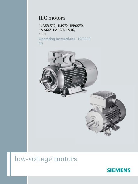
IEC motors<br />
1LA5/6/7/9, 1LP7/9, 1PP6/7/9,<br />
1MA6/7, 1MF6/7, 1MJ6,<br />
1LE1<br />
Operating Instructions · 10/2008<br />
en<br />
low-voltage motors
HIntroduction 1<br />
HSafety information 2<br />
HDescription 3<br />
Low-Voltage <strong>Motors</strong><br />
1LA5/6/7/9, 1LP7/9, 1PP6/7/9,<br />
1MA6/7, 1MF6/7, 1MJ6, 1LE1<br />
Operating Instructions<br />
HAssignment planning 4<br />
HMounting, installation 5<br />
HCommissioning<br />
6<br />
HOperation<br />
7<br />
HMaintenance<br />
8<br />
HSpare parts/accessories<br />
9<br />
HNotes<br />
10<br />
HAppendix<br />
A<br />
10/2008<br />
5 610 00000 02 000
Legal information<br />
Warning notice system<br />
This manual contains notices you have to observe in order to ensure your personal safety, as well as to prevent<br />
damage to property. The notices referring to your personal safety are highlighted in the manual by a safety alert<br />
symbol, notices referring only to property damage have no safety alert symbol. These notices shown below are<br />
graded according to the degree of danger.<br />
DANGER<br />
indicates that death or severe personal injury will result if proper precautions are not taken.<br />
WARNING<br />
indicates that death or severe personal injury may result if proper precautions are not taken.<br />
CAUTION<br />
with a safety alert symbol, indicates that minor personal injury can result if proper precautions are not taken.<br />
CAUTION<br />
without a safety alert symbol, indicates that property damage can result if proper precautions are not taken.<br />
NOTICE<br />
indicates that an unintended result or situation can occur if the corresponding information is not taken into<br />
account.<br />
If more than one degree of danger is present, the warning notice representing the highest degree of danger will<br />
be used. A notice warning of injury to persons with a safety alert symbol may also include a warning relating to<br />
property damage.<br />
Qualified Personnel<br />
The device/system may only be set up and used in conjunction with this documentation. Commissioning and<br />
operation of a device/system may only be performed by qualified personnel. Within the context of the safety notes<br />
in this documentation qualified persons are defined as persons who are authorized to commission, ground and<br />
label devices, systems and circuits in accordance with established safety practices and standards.<br />
Proper use of <strong>Siemens</strong> products<br />
Note the following:<br />
WARNING<br />
<strong>Siemens</strong> products may only be used for the applications described in the catalog and in the relevant technical<br />
documentation. If products and components from other manufacturers are used, these must be recommended<br />
or approved by <strong>Siemens</strong>. Proper transport, storage, installation, assembly, commissioning, operation and<br />
maintenance are required to ensure that the products operate safely and without any problems. The permissible<br />
ambient conditions must be adhered to. The information in the relevant documentation must be observed.<br />
Trademarks<br />
All names identified by ® are registered trademarks of the <strong>Siemens</strong> AG. The remaining trademarks in this<br />
publication may be trademarks whose use by third parties for their own purposes could violate the rights of the<br />
owner.<br />
Disclaimer of Liability<br />
We have reviewed the contents of this publication to ensure consistency with the hardware and software<br />
described. Since variance cannot be precluded entirely, we cannot guarantee full consistency. However, the<br />
information in this publication is reviewed regularly and any necessary corrections are included in subsequent<br />
editions.<br />
<strong>Siemens</strong> AG<br />
Industry Sector<br />
Postfach 48 48<br />
90026 NÜRNBERG<br />
GERMANY<br />
Ordernumber: 5 610 00000 02 000<br />
P 10/2008<br />
Copyright © <strong>Siemens</strong> AG .<br />
Technical data subject to change
Table of contents<br />
H1<br />
H2<br />
H3<br />
H4<br />
H5<br />
HIntroduction ............................................................................................................................................... H7<br />
H1.1<br />
HAbout these operating instructions ............................................................................................... H7<br />
HSafety information ..................................................................................................................................... H9<br />
H2.1<br />
H2.2<br />
HGeneral safety instructions ........................................................................................................... H9<br />
HSpecial conditions for explosion-proof machines ....................................................................... H10<br />
HDescription .............................................................................................................................................. H11<br />
H3.1<br />
H3.1.1<br />
H3.1.2<br />
H3.2<br />
H3.3<br />
H3.4<br />
H3.5<br />
H3.5.1<br />
H3.5.2<br />
H3.5.3<br />
H3.5.3.1<br />
H3.5.3.2<br />
H3.5.3.3<br />
H3.5.4<br />
H3.5.5<br />
H3.5.6<br />
H3.5.7<br />
H3.5.8<br />
HContact ....................................................................................................................................... H11<br />
HSIEMENS Service Center........................................................................................................... H11<br />
HLanguage versions on the Internet............................................................................................. H11<br />
HRange of application................................................................................................................... H12<br />
HDelivery....................................................................................................................................... H12<br />
HRating plate................................................................................................................................. H13<br />
Hnstallation.................................................................................................................................... H15<br />
HMachine design........................................................................................................................... H15<br />
HRegulations................................................................................................................................. H15<br />
HCooling and ventilation ............................................................................................................... H17<br />
HGeneral ....................................................................................................................................... H17<br />
HMachines with a fan.................................................................................................................... H17<br />
HMachines without a fan (optional)............................................................................................... H19<br />
HBearings...................................................................................................................................... H19<br />
HBalancing .................................................................................................................................... H19<br />
HTypes of construction/method of installation .............................................................................. H20<br />
HDegree of protection ................................................................................................................... H21<br />
HOptional built-on and built-in accessories................................................................................... H22<br />
HAssignment planning ............................................................................................................................... H23<br />
H4.1<br />
H4.2<br />
H4.3<br />
H4.4<br />
H4.5<br />
HTransport .................................................................................................................................... H23<br />
HStorage ....................................................................................................................................... H24<br />
HBearing lifetime........................................................................................................................... H24<br />
HElectromagnetic compatibility..................................................................................................... H25<br />
HDisposal...................................................................................................................................... H25<br />
HMounting, installation .............................................................................................................................. H27<br />
H5.1<br />
H5.1.1<br />
H5.1.2<br />
H5.1.3<br />
H5.1.4<br />
H5.2<br />
H5.2.1<br />
H5.2.1.1<br />
HInstallation .................................................................................................................................. H27<br />
HSafety instructions ...................................................................................................................... H27<br />
HMachine installation.................................................................................................................... H27<br />
HBalancing.................................................................................................................................... H30<br />
HNoise emission ........................................................................................................................... H32<br />
HAlignment and fastening............................................................................................................. H32<br />
HGeneral measures...................................................................................................................... H32<br />
HFoot dimensions ......................................................................................................................... H33<br />
1LA5/6/7/9, 1LP7/9, 1PP6/7/9, 1MA6/7, 1MF6/7, 1MJ6, 1LE1<br />
Operating Instructions, 10/2008, 5 610 00000 02 000 3
Table of contents<br />
H6<br />
H7<br />
H8<br />
H5.3<br />
H5.3.1<br />
H5.3.1.1<br />
H5.3.1.2<br />
H5.3.1.3<br />
H5.3.1.4<br />
H5.3.1.5<br />
H5.3.1.6<br />
H5.3.1.7<br />
H5.3.2<br />
H5.3.2.1<br />
H5.3.2.2<br />
H5.3.2.3<br />
H5.3.2.4<br />
H5.3.2.5<br />
H5.3.3<br />
H5.3.4<br />
H5.3.4.1<br />
H5.3.5<br />
HConnecting.................................................................................................................................. H34<br />
HConnection of the machine......................................................................................................... H34<br />
HElectrical connection................................................................................................................... H34<br />
HTerminal designations ................................................................................................................ H35<br />
HDirection of rotation .................................................................................................................... H36<br />
HConnection with/without cable lugs ............................................................................................ H36<br />
HConnecting protruding cables..................................................................................................... H36<br />
HCable entry ................................................................................................................................. H37<br />
HTerminal box............................................................................................................................... H41<br />
HTightening torques...................................................................................................................... H44<br />
HGeneral notes ............................................................................................................................. H44<br />
HElectrical connections - Termincal board connections ............................................................... H44<br />
HCable glands............................................................................................................................... H45<br />
HTerminal boxes, end shields, grounding conductors, sheet metal fan covers ........................... H45<br />
HConductor connection................................................................................................................. H46<br />
HConnecting the ground conductor .............................................................................................. H50<br />
HConnection of optional built-on accessories............................................................................... H51<br />
HExternal fan, incremental encoder, brake................................................................................... H51<br />
HConnection to the converter ....................................................................................................... H52<br />
HCommissioning........................................................................................................................................ H53<br />
H6.1<br />
H6.2<br />
H6.3<br />
HChecking the insulation resistance............................................................................................. H53<br />
HMeasures before start-up ........................................................................................................... H55<br />
HSwitching on ............................................................................................................................... H56<br />
HOperation ................................................................................................................................................ H57<br />
H7.1<br />
H7.2<br />
H7.3<br />
H7.4<br />
H7.5<br />
H7.5.1<br />
H7.5.2<br />
H7.5.3<br />
H7.5.4<br />
H7.5.5<br />
HSafety instructions ...................................................................................................................... H57<br />
HStoppages................................................................................................................................... H59<br />
HFault tables ................................................................................................................................. H60<br />
HDeactivating................................................................................................................................ H61<br />
HClass........................................................................................................................................... H62<br />
HZone 1 with type of protection Ex de II (Flameproof Enclosure "d" for the machine and<br />
Increased Safety "e" for the terminal box) .................................................................................. H62<br />
HZone 1 with Ex e II type of protection (Increased Safety "e")..................................................... H62<br />
HZone 2 with type of protection Ex nA II (non-sparking) .............................................................. H63<br />
HZone 21....................................................................................................................................... H63<br />
HZone 22....................................................................................................................................... H64<br />
HMaintenance............................................................................................................................................ H65<br />
H8.1<br />
H8.2<br />
H8.2.1<br />
H8.2.2<br />
H8.2.3<br />
H8.2.4<br />
H8.3<br />
H8.3.1<br />
H8.3.2<br />
H8.3.3<br />
H8.3.4<br />
HPreparation and notes ................................................................................................................ H65<br />
HMaintenance ............................................................................................................................... H66<br />
HMaintenance intervals................................................................................................................. H66<br />
HRegreasing (optional) ................................................................................................................. H67<br />
HCleaning...................................................................................................................................... H67<br />
HDrain condensate ....................................................................................................................... H68<br />
HInspection ................................................................................................................................... H68<br />
HGeneral inspection specifications............................................................................................... H68<br />
HOptional built-on accessories ..................................................................................................... H69<br />
HInitial inspection .......................................................................................................................... H69<br />
HMain inspection........................................................................................................................... H70<br />
1LA5/6/7/9, 1LP7/9, 1PP6/7/9, 1MA6/7, 1MF6/7, 1MJ6, 1LE1<br />
4 Operating Instructions, 10/2008, 5 610 00000 02 000
Table of contents<br />
H9<br />
H10<br />
HA<br />
H8.4<br />
H8.4.1<br />
H8.4.2<br />
H8.4.3<br />
H8.4.4<br />
H8.4.5<br />
H8.4.6<br />
H8.4.7<br />
H8.4.8<br />
H8.4.9<br />
HCorrective maintenance ............................................................................................................. H70<br />
HInstructions for repair.................................................................................................................. H70<br />
HStorage ....................................................................................................................................... H71<br />
HDismantling................................................................................................................................. H72<br />
HAssemly ...................................................................................................................................... H74<br />
HScrew-type connections ............................................................................................................. H76<br />
HElectrical connections - Termincal board connections............................................................... H76<br />
HCable glands............................................................................................................................... H76<br />
HTerminal boxes, end shields, grounding conductors, sheet metal fan covers ........................... H77<br />
HOptional built-on accessories ..................................................................................................... H78<br />
HSpare parts/accessories.......................................................................................................................... H79<br />
H9.1<br />
H9.2<br />
H9.3<br />
H9.4<br />
H9.4.1<br />
H9.4.2<br />
H9.4.3<br />
H9.4.4<br />
H9.4.5<br />
H9.4.6<br />
H9.4.7<br />
H9.4.8<br />
H9.4.9<br />
H9.4.10<br />
HSpare parts ordering................................................................................................................... H79<br />
HSpare parts ................................................................................................................................. H80<br />
HStandardized parts ..................................................................................................................... H83<br />
HExploded drawings ..................................................................................................................... H85<br />
H1LA,1LP,1MA,1MF,1PP6/7/9 FS 56...90L ................................................................................. H85<br />
H1LA,1LP,1MA,1MF,1PP6/7/9 FS 100...160 ............................................................................... H86<br />
H1LA5180...225 ............................................................................................................................ H87<br />
H1MA6180...200 ........................................................................................................................... H88<br />
HTerminal box 1MA6180...200 ..................................................................................................... H89<br />
H1MJ6070...200............................................................................................................................ H90<br />
HTerminal box 1MJ6070...160...................................................................................................... H91<br />
HTerminal box 1MJ6180...200 (Ex e) ........................................................................................... H92<br />
HTerminal box 1MJ6180...200 (Ex d) ........................................................................................... H93<br />
H1LE1... ........................................................................................................................................ H94<br />
HNotes....................................................................................................................................................... H95<br />
HAppendix ................................................................................................................................................. H97<br />
HA.1<br />
HDirectory ..................................................................................................................................... H97<br />
HGlossary.................................................................................................................................................. H99<br />
1LA5/6/7/9, 1LP7/9, 1PP6/7/9, 1MA6/7, 1MF6/7, 1MJ6, 1LE1<br />
Operating Instructions, 10/2008, 5 610 00000 02 000 5
Introduction 1<br />
1.1 About these operating instructions<br />
These operating instructions describe the machine and explain best practices in machine<br />
handling, from initial delivery to final disposal of the equipment.<br />
Read these operating instructions before you handle the machine to become familiar with its<br />
design and operating principles and thus ensure safe, problem-free machine operation and<br />
long service life.<br />
<strong>Siemens</strong> strives continually to improve the quality of information provided in these operating<br />
instructions. If you find any mistakes or would like to offer suggestions about how this<br />
document could be improved, please contact the HSIEMENS Service Center (Page H11).<br />
Always follow the safety instructions and notices in these operating instructions. The warning<br />
notice system is explained on the rear of the inside front.<br />
Note on reading the operating instructions<br />
Explanation of icons<br />
Note for 1LE1 machines<br />
Note for explosion-proof machines<br />
1LA5/6/7/9, 1LP7/9, 1PP6/7/9, 1MA6/7, 1MF6/7, 1MJ6, 1LE1<br />
Operating Instructions, 10/2008, 5 610 00000 02 000 7
Safety information 2<br />
2.1 General safety instructions<br />
The safe use of electrical machines<br />
WARNING<br />
Rotating or live parts<br />
Rotating or live parts are dangerous.<br />
Fatal or severe injuries and substantial material damage can occur if the required covers<br />
are removed or if the machines are not handled, operated, or maintained properly.<br />
Only remove covers in accordance with regulations and operate machines correctly.<br />
Perform regular maintenance on the machine.<br />
Qualified personnel<br />
These operating instructions only contain the information that is necessary for the machines<br />
to be used by qualified personnel in accordance with their intended purpose.<br />
Those responsible for plant safety must ensure the following:<br />
● The basic planning work for the system and all work relating to transportation, assembly,<br />
installation, commissioning, maintenance and repairs is carried out by qualified personnel<br />
and checked by responsible, suitably skilled personnel.<br />
● The operating instructions and machine documentation are always available.<br />
● The technical data and specifications relating to installation, connection, ambient and<br />
operating conditions are taken into account at all times.<br />
● The system-specific installation and safety regulations are observed.<br />
● Personal protective equipment is used.<br />
● Work on or in the vicinity of these machines by unqualified persons is prohibited.<br />
● If the machines are used outside industrial areas, the installation site must be<br />
safeguarded against unauthorized access by means of suitable protection facilities (e.g.,<br />
safety gates) and appropriate warning signs.<br />
Note<br />
<strong>Siemens</strong> Service Center<br />
We recommend engaging the support and services of your local <strong>Siemens</strong> Service Center<br />
for all planning, installation, commissioning, and maintenance work.<br />
1LA5/6/7/9, 1LP7/9, 1PP6/7/9, 1MA6/7, 1MF6/7, 1MJ6, 1LE1<br />
Operating Instructions, 10/2008, 5 610 00000 02 000 9
Safety information<br />
2.2 Special conditions for explosion-proof machines<br />
WARNING<br />
Electrical machines have hazardous, live and rotating parts and may also have hot<br />
surfaces.<br />
NOTICE<br />
Special designs and construction versions<br />
If any problems or uncertainties arise, we urgently recommend that you contact the<br />
manufacturer specifying the type designation and serial number (No. ...., see nameplate) or<br />
have the equipment repaired by a <strong>Siemens</strong> Service Center.<br />
2.2 Special conditions for explosion-proof machines<br />
Special conditions for the safe application of machines marked with X (excerpt from the EC<br />
type-examination certificate, point 17)<br />
Flameproof enclosure "d"<br />
Flameproof joints may only be repaired in accordance with the manufacturer's<br />
design specifications. Repairing in accordance with the values in Table 1 and 2 of<br />
EN 60079-1 is not permitted.<br />
Zone 21<br />
- <strong>Motors</strong> may not be in operated in excessively deep dust deposits.<br />
- When installing motors with the free shaft end facing upwards, foreign bodies must<br />
be prevented from falling into vent holes through the mounting.<br />
- For motors with a fixed connection cable: The free end of the cable must be<br />
connected according to valid regulations for electrical installations.<br />
1LA5/6/7/9, 1LP7/9, 1PP6/7/9, 1MA6/7, 1MF6/7, 1MJ6, 1LE1<br />
10 Operating Instructions, 10/2008, 5 610 00000 02 000
Description 3<br />
3.1 Contact<br />
3.1.1 SIEMENS Service Center<br />
Contact for further information<br />
Details regarding the design of this electrical machine and the permissible operating<br />
conditions are described in these operating instructions.<br />
If you wish to request a field service visit or order spare parts, please contact your local<br />
<strong>Siemens</strong> sales office. This office will contact the responsible service center on your behalf.<br />
If you have any technical queries or you require additional information, please contact the<br />
<strong>Siemens</strong> Service Center.<br />
Table 3- 1<br />
Technical support<br />
Europe - Germany: Phone: +49 (0)180 - 50 50 222<br />
Fax +49 (0)180 - 50 50 223<br />
America - USA: Phone: +1 423 262 2522<br />
Asia - China: Phone: +86 1064 719 990<br />
E-Mail:<br />
support.automation@siemens.com<br />
Internet English:<br />
http://www.siemens.com/automation/support-request<br />
Internet Deutsch:<br />
http://www.siemens.de/automation/support-request<br />
3.1.2 Language versions on the Internet<br />
Internet page: <br />
If you require additional language versions, please contact the above-named <strong>Siemens</strong><br />
Service Center.<br />
1LA5/6/7/9, 1LP7/9, 1PP6/7/9, 1MA6/7, 1MF6/7, 1MJ6, 1LE1<br />
Operating Instructions, 10/2008, 5 610 00000 02 000 11
Description<br />
3.2 Range of application<br />
3.2 Range of application<br />
Overview<br />
The three-phase machines of this series are used as industrial drives. They are designed for<br />
a wide range of drive technology applications both for mains operation as well as in<br />
conjunction with frequency converters.<br />
They are characterized by their high power density, extreme robustness, long service life<br />
and outstanding reliability.<br />
Intended use of the machines<br />
These machines are intended for industrial installations. They comply with the harmonized<br />
standards of the series IEC / EN 60034-1 (VDE 0530-1). Their use in hazardous areas is<br />
forbidden unless the marking on the nameplate expressly permits this operation. If<br />
other/more wide-ranging demands (e.g. protection against touching by children) are made in<br />
special cases – i.e. use in non-industrial installations – these conditions must have been<br />
complied with in the installation when the motors are installed.<br />
Note<br />
Machine directive<br />
Low-voltage machines are components for installation in machines which comply with<br />
machine directive 2006/42/EG. They must not be started up until the end product has been<br />
verified as complying with this directive (refer to EN 60204-1).<br />
3.3 Delivery<br />
Checking the delivery for completeness<br />
The drive systems are put together on an individual basis. When you take receipt of the<br />
delivery, please check immediately whether the items delivered are in accordance with the<br />
accompanying documents. <strong>Siemens</strong> will not accept any claims relating to items missing from<br />
the delivery and which are submitted at a later date.<br />
Register a complaint about<br />
● any apparent transport damage with the delivery agent immediately.<br />
● any apparent defects/missing components with the appropriate SIEMENS office<br />
immediately.<br />
The safety and start-up instructions are part of the scope of supply and must therefore be<br />
stored in an accessible place. This also applies to the operating instructions, which are<br />
available as an option.<br />
The rating plate optionally enclosed as a loose item with the delivery is provided to enable<br />
the machine data to be shown on or near the machine or installation.<br />
1LA5/6/7/9, 1LP7/9, 1PP6/7/9, 1MA6/7, 1MF6/7, 1MJ6, 1LE1<br />
12 Operating Instructions, 10/2008, 5 610 00000 02 000
Description<br />
3.4 Rating plate<br />
3.4 Rating plate<br />
Technical specifications<br />
The machine nameplate contains the technical specifications valid for the delivered machine.<br />
The machine nameplate consists of the following technical specifications:<br />
Examples of nameplates<br />
Table 3- 2<br />
Machine nameplate<br />
Item Technical specifications Item Technical specifications<br />
1 Machine type: Three-phase low-voltage 10 Temperature class<br />
machine<br />
2 Order no. 11 Standards and regulations<br />
3 Factory number (ID no., serial number) 12 Date of manufacture YYMM<br />
4 Type of construction 13 Additional approvals (optional)<br />
5 Degree of protection 14 Installation altitude (only if higher than 1000 m)<br />
6 50 Hz data 15 Customer data (optional)<br />
7 60 Hz data 16 Operating temperature range (only if different from<br />
the standard)<br />
8 Frame size 17 Identification number of testing agency (optional)<br />
9 Machine weight<br />
<br />
<br />
<br />
<br />
<br />
<br />
3~Mot. 1LA7166-2AA60<br />
<br />
D-91056 Erlangen<br />
<br />
<br />
<br />
<br />
<br />
0,91 <br />
0,92 <br />
<br />
<br />
<br />
<br />
<br />
<br />
<br />
<br />
<br />
<br />
<br />
<br />
<br />
<br />
<br />
1LA5/6/7/9, 1LP7/9, 1PP6/7/9, 1MA6/7, 1MF6/7, 1MJ6, 1LE1<br />
Operating Instructions, 10/2008, 5 610 00000 02 000 13
Description<br />
3.4 Rating plate<br />
Table 3- 3<br />
Machine nameplate 1LE1<br />
Item Technical specifications Item Technical specifications<br />
1 Machine type: Three-phase low-voltage<br />
machine<br />
13 Voltage range V<br />
2 Order no. 14 Current range A<br />
3 Factory number (ID no., serial number) 15<br />
4 Type of construction 16 Machine weight kg<br />
5 Degree of protection 17 Standards and regulations<br />
6 Rated voltage [V] and winding connection 18 Temperature class<br />
7 Frequency Hz 19 Frame size<br />
8 Rated current A 20 Additional details (optional)<br />
9 Rated power kW 21 Operating temperature range (only if different from<br />
the standard)<br />
10 Power factor cosφ 22 Installation altitude (only if higher than 1000 m)<br />
11 Efficiency 23 Customer data (optional)<br />
12 Rated speed [1/min] 24 Date of manufacture YYMM<br />
<br />
<br />
<br />
<br />
<br />
<br />
<br />
<br />
<br />
<br />
<br />
D-91056 Erlangen<br />
3~Mot. 1LE10021DB434AA0 E0605/0496382 02 001<br />
IEC/EN 60034 160L IMB3 IP55<br />
73 kg Th.Cl. 155 (F)<br />
Bearing<br />
DE 6209-2ZC3<br />
NE 6209-2ZC3<br />
V<br />
400<br />
690<br />
460<br />
Y<br />
Hz<br />
50<br />
50<br />
60<br />
A<br />
29,5<br />
17,1<br />
29,5<br />
kW<br />
15<br />
cosφ<br />
0,82<br />
eta<br />
89,4%<br />
1/min<br />
1460<br />
15 0,82 89,4% 1460<br />
17,3 0,82 89,4% 1760<br />
V A<br />
380-420 30,0-30,2<br />
660-725 17,4-17,5<br />
440-480 30,2-29,8<br />
<br />
<br />
<br />
<br />
<br />
1LA5/6/7/9, 1LP7/9, 1PP6/7/9, 1MA6/7, 1MF6/7, 1MJ6, 1LE1<br />
14 Operating Instructions, 10/2008, 5 610 00000 02 000
Description<br />
3.5 nstallation<br />
3.5 nstallation<br />
3.5.1 Machine design<br />
Machines of this series are self-ventilated low-voltage three-phase asynchronous drives with<br />
a cylindrical shaft end and featherkey way. They can be supplied as single-speed machines<br />
with different efficiency classes or as pole changing machines for several speeds.<br />
In the case of machines with feet (IM B3 type of construction), the feet are cast or bolted on.<br />
The position of the feet bolted onto the housing of the machine can be changed, e.g. in order<br />
to change the position of the terminal box, but this must only be done by authorized partners.<br />
The surfaces on which the feet rested must then be evened out and made parallel with the<br />
machine shaft, if necessary by placing shims underneath the machine. Any damaged<br />
paintwork must be correctly repaired.<br />
3.5.2 Regulations<br />
Overview<br />
The machines comply with the following standards:<br />
Table 3- 4<br />
Applicable general regulations<br />
Feature<br />
Standard<br />
Dimensions and operating performance IEC / EN 60034-1<br />
Degree of protection IEC / EN 60034-5<br />
Cooling IEC / EN 60034-6<br />
Type of construction IEC / EN 60034-7<br />
Terminal designations and direction of rotation IEC / EN 60034-8<br />
Noise emission IEC / EN 60034-9<br />
Restart characteristics for rotating electrical machines IEC / EN 60034-12<br />
Vibration severity grades IEC / EN 60034-14<br />
IEC standard voltages IEC 60038<br />
1LA5/6/7/9, 1LP7/9, 1PP6/7/9, 1MA6/7, 1MF6/7, 1MJ6, 1LE1<br />
Operating Instructions, 10/2008, 5 610 00000 02 000 15
Description<br />
3.5 nstallation<br />
Supplementary regulations for<br />
explosion-proof machines<br />
Table 3- 5<br />
Applicable regulations for explosion-proof machines<br />
Feature<br />
Electrical equipment for hazardous gas atmospheres, Part 0: General<br />
requirements<br />
Electrical equipment for hazardous gas atmospheres, Part 1: Flameproof<br />
enclosure "d"<br />
Electrical equipment for hazardous gas atmospheres, Part 7: Increased<br />
safety "e"<br />
Electrical equipment for hazardous gas atmospheres, Part 14: Electric<br />
installations for endangered atmospheres (except underground<br />
excavation)<br />
Electrical equipment for hazardous gas atmospheres, Part 15: Type of<br />
protection "n"<br />
Electrical equipment for hazardous gas atmospheres, Part 19: Repairs and<br />
overhauls<br />
Electrical equipment for use in the presence of combustible dust - Part 0:<br />
General requirements<br />
Electrical equipment for use in the presence of combustible dust - Part 1:<br />
Protection by enclosure "tD"<br />
Electrical equipment for use in the presence of combustible dust - Part 17:<br />
Inspection and maintenance of electrical systems in hazardous areas<br />
(except underground excavation)<br />
Directive on the approximation of the laws of the Member States<br />
concerning equipment and protective systems intended for use in<br />
hazardous areas.<br />
Standard<br />
IEC / EN 60079-0<br />
IEC / EN 60079-1<br />
IEC / EN 60079-7<br />
IEC / EN 60079-14<br />
IEC / EN 60079-15<br />
IEC / EN 60079-19<br />
IEC / EN 61241-0<br />
IEC / EN 61241-1<br />
IEC / EN 61241-17<br />
RL94/9/EC<br />
1LA5/6/7/9, 1LP7/9, 1PP6/7/9, 1MA6/7, 1MF6/7, 1MJ6, 1LE1<br />
16 Operating Instructions, 10/2008, 5 610 00000 02 000
Description<br />
3.5 nstallation<br />
3.5.3 Cooling and ventilation<br />
3.5.3.1 General<br />
The machines of this series are three-phase asynchronous machines with a closed primary<br />
(internal) cooling circuit and an open secondary cooling circuit (surface cooling). The form of<br />
surface cooling can vary depending on the type of cooling provided:<br />
3.5.3.2 Machines with a fan<br />
Self-ventilation (standard): Type of cooling IC 411 in accordance with IEC / EN 60034-6<br />
Located at the ND end of the stator housing is an air intake cowl that guides the external air<br />
on its way to the motor. The external air is drawn in through openings in the air intake cowl<br />
and flows axially across the outer cooling ribs of the motor frame. The fan wheel responsible<br />
for the external flow of cool air is fastened to the machine shaft.<br />
The fan wheels are independent of the direction of rotation.<br />
In the case of frequent switching or braking or if the speed is controlled continually below the<br />
nominal speed, the cooling effect must be checked.<br />
Machines for use in Zone 21 and Zone 22 have a metal fan.<br />
Figure 3-1<br />
Self-ventilation<br />
1LA5/6/7/9, 1LP7/9, 1PP6/7/9, 1MA6/7, 1MF6/7, 1MJ6, 1LE1<br />
Operating Instructions, 10/2008, 5 610 00000 02 000 17
Description<br />
3.5 nstallation<br />
Forced ventilation (optional): Type of cooling IC 416 in accordance with IEC / EN 60034-6<br />
Cooling independent of the speed is achieved by means of a separately driven fan wheel<br />
(forced ventilation). Forced ventilation is independent of the operating state of the machine. It<br />
must be ensured that the machine is not operated without starting the external fan.<br />
The fan wheel for the external flow of cold air is powered by an independent module and is<br />
enclosed by the fan cowl.<br />
Figure 3-2<br />
Forced ventilation<br />
1LA5/6/7/9, 1LP7/9, 1PP6/7/9, 1MA6/7, 1MF6/7, 1MJ6, 1LE1<br />
18 Operating Instructions, 10/2008, 5 610 00000 02 000
Description<br />
3.5 nstallation<br />
3.5.3.3 Machines without a fan (optional)<br />
Surface cooling by free convection: Type of cooling IC 410 in accordance with IEC / EN 60034-6<br />
<br />
Figure 3-3<br />
IC410<br />
Surface cooling by relative movement of cooling air: Type of cooling IC 418 in accordance with IEC /<br />
EN 60034-6<br />
<br />
Figure 3-4<br />
IC418<br />
3.5.4 Bearings<br />
In order to support the machine shaft and maintain its position in the non-moving part of the<br />
machine, only 2 rolling-contact bearings are used. One rolling-contact bearing performs the<br />
function of a location bearing which transfers axial and radial forces from the rotatable<br />
machine shaft to the non-moving part of the machine. The second rolling-contact bearing is a<br />
floating/guide bearing in order to allow thermal expansion inside the machine and transfer<br />
radial forces.<br />
The nominal (calculated) useful life of the bearings (ISO 281) is 20,000 hours if the<br />
permissible radial/axial forces are fully utilized. However, the achievable useful life of the<br />
bearings can be considerably longer in the case of smaller forces (e.g. coupling mode).<br />
The rolling-contact bearings are lubricated for life (standard feature) and therefore do not<br />
require maintenance.<br />
If the option for re-lubrication is taken up, the information on the rating plate must be<br />
complied with.<br />
3.5.5 Balancing<br />
The machines are balanced dynamically with a half featherkey (code "H") in accordance with<br />
ISO 8821.<br />
The balancing quality corresponds to vibration severity grade "A" for the complete machine;<br />
vibration severity grade "B" is possible as an option.<br />
1LA5/6/7/9, 1LP7/9, 1PP6/7/9, 1MA6/7, 1MF6/7, 1MJ6, 1LE1<br />
Operating Instructions, 10/2008, 5 610 00000 02 000 19
Description<br />
3.5 nstallation<br />
3.5.6 Types of construction/method of installation<br />
Further possible fields of application<br />
The type of construction of the machine is stated on the rating plate.<br />
CAUTION<br />
During transport, machines may only be hoisted in a position corresponding to their basic<br />
type of construction.<br />
Table 3- 6<br />
Type of construction<br />
Basic type of construction<br />
code<br />
Graphics-Based<br />
Representation<br />
Other methods of installation<br />
Graphics-Based<br />
Representation<br />
IM B3 (IM 1001) IM V5 (IM 1011)<br />
IM V6 (IM 1031)<br />
IM B6 (IM 1051)<br />
IM B7 (IM 1061)<br />
IM B8 (IM 1071)<br />
Basic type of construction<br />
code<br />
Graphics-Based<br />
Representation<br />
Other methods of installation<br />
Graphics-Based<br />
Representation<br />
IM B5 (IM 3001) IM V1 (IM 3011)<br />
IM V3 (IM 3031)<br />
Basic type of construction<br />
code<br />
Graphics-Based<br />
Representation<br />
Other methods of installation<br />
Graphics-Based<br />
Representation<br />
IM B14 (IM 3601) IM V18 (IM 3611)<br />
IM V19 (IM 3631)<br />
Basic type of construction<br />
code<br />
Graphics-Based<br />
Representation<br />
IM B35 (IM 2001)<br />
IM B34 (IM 2101)<br />
1LA5/6/7/9, 1LP7/9, 1PP6/7/9, 1MA6/7, 1MF6/7, 1MJ6, 1LE1<br />
20 Operating Instructions, 10/2008, 5 610 00000 02 000
Description<br />
3.5 nstallation<br />
Other possible fields of application for explosion-proof machines<br />
The type of construction of the machine is stated on the nameplate.<br />
DANGER<br />
In the case of explosion-proof machines where the shaft extensions point downwards<br />
(types of construction IM V5, IM V1 or IM V18 ) a protective top cover is mandatory. A<br />
protective top cover is automatically installed at the factory for explosion-proof motors with<br />
IM V5, IM V1 or IM V18 types of construction. For types of construction with shaft extension<br />
pointing upwards, a suitable cover must be implemented to prevent small parts from falling<br />
into the fan cover (see the standard IEC/EN 60079-0). The cover must not block the cooling<br />
air flow.<br />
Table 3- 7<br />
Construction type with protective top cover<br />
Conditions of installation<br />
Graphics-Based Representation<br />
IM V5 (IM 1011)<br />
IM V1 (IM 3011)<br />
IM V18 (IM 3611)<br />
3.5.7 Degree of protection<br />
The machines have degree of protection IP 55 (see rating plate). They can be installed in<br />
dusty or humid environments.<br />
NOTICE<br />
Condensation holes<br />
In order to comply with the degree of protection, any existing condensation holes are to be<br />
sealed!<br />
If the machines are used or are stored outdoors, we recommend that they be kept under<br />
some sort of additional cover so that they are not subjected to direct intensive solar radiation,<br />
rain, snow, ice or dust over a long period of time.<br />
In such cases, technical consultation may be appropriate.<br />
The machines are suitable for use in the tropics.<br />
Guide value of 60% relative humidity at a coolant temperature (CT) of 40° C.<br />
Ambient temperature: -20° C to +40° C<br />
Installation altitude: ≤ 1000 m<br />
1LA5/6/7/9, 1LP7/9, 1PP6/7/9, 1MA6/7, 1MF6/7, 1MJ6, 1LE1<br />
Operating Instructions, 10/2008, 5 610 00000 02 000 21
Description<br />
3.5 nstallation<br />
If the specified ambient conditions are different to these values, they must be indicated on<br />
the rating plate. These values will then be applicable.<br />
Machines intended for use in Zone 1 (type of protection Flameproof Enclosure "d"<br />
or Increased Safety "e") or in Zone 2 (type of protection "n") are designed with IP 55<br />
degree of protection.<br />
Machines intended for use in Zone 21 have IP 65 degree of protection. Machines<br />
intended for use in Zone 22 have IP 55 degree of protection and can be used in<br />
dusty environments such as grinders, silos, animal feed plants, and malthouses, as<br />
well as in certain areas of the chemical industry.<br />
3.5.8 Optional built-on and built-in accessories<br />
In addition to the current-dependent overload protective device located in the connecting<br />
leads, we recommend that you use temperature sensors embedded in the stator winding in<br />
order to monitor the temperature and protect the stator winding from overheating.<br />
Machines whose winding is exposed to the danger of condensation due to the climate, e.g.<br />
machines at a standstill in a damp environment or machines which are exposed to large<br />
temperature fluctuations, can be fitted with an anti-condensation heater.<br />
As an option, the machines can be fitted with additional built-on accessories on the<br />
ventilation side (e.g. brake, rotary pulse encoder).<br />
No additional measures are required in the case of external sources of heat or<br />
cold, provided that the temperatures are within limits at the relevant location.<br />
Special application cases involving external sources of heat and cold should be<br />
investigated in respect of how maximum surface and operating temperatures<br />
are affected. This should be carried out by means of type tests, and appropriate<br />
measures implemented as necessary.<br />
Built-on accessories such as brakes, forced ventilation or pulse encoders must<br />
be selected for conformity to the specifications of Directive 94/9/EC.<br />
1LA5/6/7/9, 1LP7/9, 1PP6/7/9, 1MA6/7, 1MF6/7, 1MJ6, 1LE1<br />
22 Operating Instructions, 10/2008, 5 610 00000 02 000
Assignment planning 4<br />
4.1 Transport<br />
Use lifting eyes<br />
CAUTION<br />
During transport, all the lifting eyes on the machine are to be used and any eyes which are<br />
screwed in must be firmly tightented. They are designed to bear the weight of the machine<br />
alone and therefore no additional loads should be added. Eyebolts are to be screwed in<br />
right up to their supporting surface. If necessary, use suitable rated transport materials such<br />
as lifting straps (EN 1492-1) and lashing straps (EN12195-2).<br />
Suspended transport<br />
WARNING<br />
Use suitable means of conveyance for transport and during installation. If several items of<br />
transport material are used for fastening, two straps must be able to carry the whole load.<br />
Secure lifting materials to make sure they cannot slip!<br />
Remove any transport locks before start-up and either keep them in a safe place or unlock<br />
them. You can then use them again for transporting further items or you can apply them<br />
again.<br />
The machines are packed in different ways depending on how they are transported and their<br />
size. Unless agreed otherwise in the contract, the packaging is in accordance with the<br />
packing guidelines of ISPM (International Standards for Phytosanitary Measures).<br />
Comply with the images shown on the packaging. Their meaning is as follows:<br />
Up<br />
Fragile<br />
goods<br />
Protect<br />
against moisture<br />
Protect<br />
against heat<br />
Focus<br />
Do not use<br />
hand hooks<br />
Attach<br />
here<br />
1LA5/6/7/9, 1LP7/9, 1PP6/7/9, 1MA6/7, 1MF6/7, 1MJ6, 1LE1<br />
Operating Instructions, 10/2008, 5 610 00000 02 000 23
Assignment planning<br />
4.2 Storage<br />
4.2 Storage<br />
Storing outdoors<br />
If possible, choose a dry storage location which is safe from flooding and free from<br />
vibrations. Repair any damage to the packaging before putting the equipment in storage in<br />
so far as this is necessary to ensure proper storage conditions. Position machines, devices<br />
and crates on pallets, wooden beams or foundations that guarantee protection against<br />
ground dampness. Prevent the equipment from sinking into the ground and also make sure<br />
that the circulation of air underneath the equipment is not impeded.<br />
Covers or tarpaulins used to protect the equipment against the weather must not make<br />
contact with the surfaces of the stored equipment. Ensure adequate air circulation by<br />
positioning wooden spacer blocks between the equipment and such covers.<br />
CAUTION<br />
Under extreme climatic conditions, e.g., saline and/or dusty atmospheres, suitable<br />
precautions are to be taken.<br />
Storing indoors<br />
The storage rooms must be dry, free from dust, frost and vibrations and well ventilated. They<br />
must also provide protection against extreme weather conditions.<br />
Bare metal surfaces<br />
For transport, the bare parts are to be coated with anti-corrosion paint which will last for a<br />
limited amount of time (
Assignment planning<br />
4.4 Electromagnetic compatibility<br />
4.4 Electromagnetic compatibility<br />
When used in accordance with their intended purpose and operated in an electrical supply<br />
system with characteristics to EN 50160, the enclosed motors (IP 55 and higher) comply with<br />
the requirements of the EC Directive concerning electromagnetic compatibility 89/336/EEC.<br />
NOTICE<br />
If the torque levels are very unequal (e.g. when a reciprocating compressor is being driven),<br />
a non-sinusoidal machine current will be induced whose harmonics can bring about an<br />
excessive reaction on the supply system and so cause excessive emitted interference.<br />
NOTICE<br />
If operated with a frequency converter, the emitted interference varies in strength,<br />
depending on the design of the converter (type, interference suppression measures,<br />
manufacturer). In order to prevent exceeding of the limit values stipulated by EN 50081 for<br />
the drive system, consisting of machine and converter, the EMC instructions specified by<br />
the converter manufacturer must be strictly observed. If the manufacturer recommends that<br />
the cable leading to the machine be shielded, the shield is most effective if it is conductively<br />
connected over a large surface area to the metal terminal box of the machine (with metal<br />
screw-type connections).<br />
In the case of machines with built-in sensors (e.g. PTC thermistors), interference voltages<br />
resulting from the converter can occur and affect the sensor cable.<br />
Immunity to interference<br />
The machines fulfil the requirements of interference immunity in conformity with EN 50082. If<br />
machines with integrated sensors (e.g. PTC thermistors) are used, the operator himself must<br />
ensure sufficient interference immunity by selecting a suitable sensor signal lead (possible<br />
with shielding, connected in the same way as supply cable leading to machine) and a<br />
suitable evaluation unit.<br />
If the machines are operated with a converter at higher speeds than the rated speed, the<br />
mechanical speed limits (safe operating speed IEC / EN 60034-1) are to be complied with.<br />
4.5 Disposal<br />
Machines must be disposed of carefully taking into account national and local regulations in<br />
the normal recycling process or by returning the machines to the manufacturer.<br />
The following must be taken into account when disposing of a machine:<br />
● Oil and grease in accordance with the directive on used oil. No mixing with solvents,<br />
cleaner solvents or paint residues<br />
● For the purposes of recycling, the components must be separated into:<br />
- electronic scrap (encoder electronics)<br />
- scrap iron<br />
- aluminum<br />
- non-ferrous heavy metal (machine windings, worm gears)<br />
- plastic (polyamide, glass-fiber reinforced polyamide, polypropylene)<br />
1LA5/6/7/9, 1LP7/9, 1PP6/7/9, 1MA6/7, 1MF6/7, 1MJ6, 1LE1<br />
Operating Instructions, 10/2008, 5 610 00000 02 000 25
Mounting, installation 5<br />
5.1 Installation<br />
5.1.1 Safety instructions<br />
CAUTION<br />
The housing parts of electrical machines can become very hot!<br />
CAUTION<br />
It must be ensured that parts which are sensitive to temperature changes (cables etc.) do<br />
not rest against the housing of the machine.<br />
NOTICE<br />
Comply with the technical data on the plates fitted to the housing of the machine!<br />
5.1.2 Machine installation<br />
● When motors are being mounted vertically, all the existing lifting eyes and hoisting straps,<br />
if any, (DIN EN 1492-1) and/or belts (DIN EN 12195-2) should be used to stabilize the<br />
position of the motor.<br />
● When tthe machine is installed vertically with the shaft end facing downwards, a<br />
protective cover for the fan cover is recommended to prevent foreign bodies from falling<br />
into the machine.<br />
● If the motor is installed with the shaft end facing upwards, the end user must prevent the<br />
ingress of fluid along the shaft.<br />
● Do not impede ventilation! It must be ensured that discharged air - including that of<br />
adjacent items of equipment - is not immediately sucked in again.<br />
1LA5/6/7/9, 1LP7/9, 1PP6/7/9, 1MA6/7, 1MF6/7, 1MJ6, 1LE1<br />
Operating Instructions, 10/2008, 5 610 00000 02 000 27
Mounting, installation<br />
5.1 Installation<br />
● If the motors are used or stored outdoors, we recommend that they be kept under some<br />
sort of additional cover so that they are not subjected to direct intensive solar radiation,<br />
rain, snow, ice or dust over a long period of time.<br />
● It must be ensured that the maximum permissible axial and radial forces are not<br />
exceeded.<br />
Note<br />
Built-on parts (e.g. incremental encoders) are not to be used for lifting!<br />
NOTICE<br />
Screwed-in lifting eyes are to be tightened or removed after installation.<br />
CAUTION<br />
The increased level of danger in hazardous areas demands that you pay particular<br />
attention to the notes marked with .<br />
• Explosion-proof machines may only be used in suitable areas and as prescribed<br />
by the responsible supervisory body. They are responsible for determining the<br />
hazard level of each area (division into zones).<br />
An X on the certificate denotes that special conditions of the EC-type<br />
examination certification must be observed.<br />
HSpecial conditions for explosion-proof machines (Page H10)<br />
• In Germany, DIN EN 60079-14 and the German Health and Safety at Work<br />
Regulations must be observed when installing electrical systems in hazardous<br />
areas. Elsewhere, the equivalent local regulations must be observed.<br />
• The machine temperature class specified on the nameplate must be equal to or<br />
greater than the temperature class of any combustible gases that may develop.<br />
Do not impede ventilation! It must be ensured that discharged air - including that of adjacent<br />
items of equipment - is not immediately sucked in again.<br />
1LA5/6/7/9, 1LP7/9, 1PP6/7/9, 1MA6/7, 1MF6/7, 1MJ6, 1LE1<br />
28 Operating Instructions, 10/2008, 5 610 00000 02 000
Mounting, installation<br />
5.1 Installation<br />
Table 5- 1<br />
Air guidance<br />
Incorrect<br />
Correct<br />
<br />
The minimum dimension "x" for the distance between neighboring modules<br />
Frame size<br />
(FS)<br />
X<br />
mm<br />
63 ... 71 15<br />
80 ... 100 20<br />
112 25<br />
132 30<br />
160 40<br />
180 ... 225 45<br />
In the case of vertical types of machine where air enters from above, the ingress of foreign<br />
bodies and water into the air inlets is to be prevented, e.g. by using a protective cover.<br />
If the shaft end is facing upwards, the user must prevent liquid from entering along the shaft.<br />
1LA5/6/7/9, 1LP7/9, 1PP6/7/9, 1MA6/7, 1MF6/7, 1MJ6, 1LE1<br />
Operating Instructions, 10/2008, 5 610 00000 02 000 29
Mounting, installation<br />
5.1 Installation<br />
5.1.3 Balancing<br />
The rotors are balanced dynamically. The balancing quality corresponds to vibration severity<br />
grade "A" for the complete machine as standard. The optional vibration severity grade "B" is<br />
indicated on the rating plate.<br />
The declaration regarding the type of featherkey for balancing is marked on the face of the<br />
shaft end and on the rating plate.<br />
Designation:<br />
● As a standard measure, balancing is carried out dynamically with a half featherkey (code<br />
"H") in accordance with ISO 8821.<br />
● "F" means balancing with a whole featherkey (optional version).<br />
● "N" means balancing without a featherkey (optional version).<br />
The featherkey declaration on the shaft and transmission element must indicate the correct<br />
type of balancing in each case and must be correctly mounted.<br />
The balancing quality corresponds to vibration severity grade "A" for the complete machine;<br />
vibration severity grade "B" is possible as an option, i.e. in order to ensure the desired<br />
balancing quality, it must be ensured that the featherkey declarations on the hub and<br />
machine shaft complement each other in the case of a shorter or longer transmission<br />
element.<br />
Note<br />
The permissible vibration levels in line with the evaluation zones according to ISO 10816<br />
determine whether mounting and balancing have been carried out correctly. If the coupled<br />
machine does not comply with the vibration level according to EN 10816, complete dynamic<br />
balancing or an alteration to the foundations may be necessary.<br />
CAUTION<br />
It is permissible to push on or pull off transmission elements only with suitable equipment.<br />
The featherkeys are to be secured during transprot to prevent them falling out.<br />
The generally required measures for touch protection of the transmission elements are to<br />
be observed.<br />
1LA5/6/7/9, 1LP7/9, 1PP6/7/9, 1MA6/7, 1MF6/7, 1MJ6, 1LE1<br />
30 Operating Instructions, 10/2008, 5 610 00000 02 000
Mounting, installation<br />
5.1 Installation<br />
Pulling off transmission elements<br />
Pushing on transmission elements<br />
NOTICE<br />
If a machine without a transmission element is started up, the featherkey must be secured<br />
to prevent it from being thrown out.<br />
When pushing on transmission elements (coupling, gear wheel, belt pulley etc.), use the<br />
thread at the shaft end and - if possible - heat the transmission elements as required. Use<br />
suitable tools for pulling transmission elements off. When the elements are being pushed on<br />
or pulled off, it is not permissible to hit the elements (with a hammer or similar) or to apply<br />
greater radial or axial forces to the machine bearings via the shaft end than those permitted<br />
according to the catalog.<br />
1LA5/6/7/9, 1LP7/9, 1PP6/7/9, 1MA6/7, 1MF6/7, 1MJ6, 1LE1<br />
Operating Instructions, 10/2008, 5 610 00000 02 000 31
Mounting, installation<br />
5.2 Alignment and fastening<br />
5.1.4 Noise emission<br />
NOTICE<br />
When the noise that is emitted at workplaces of the personnel responsible for operating the<br />
equipment is assessed, it must be borne in mind that the A-weighted sound pressure level,<br />
measured in accordance with ISO 1680, namely 70 dB(A), is not exceeded if the threephase<br />
machines are operated with the rated output.<br />
5.2 Alignment and fastening<br />
5.2.1 General measures<br />
Make sure that the machine is level and ensure secure fastening of feet and flanges, precise<br />
alignment in the case of direct coupling, and also cleanliness of the fastening surfaces. Avoid<br />
installation-related resonances with the rotating frequency and double line frequency. Turn<br />
rotor by hand and pay attention to any unusual noises. Check the direction of rotation with<br />
the motor uncoupled.<br />
NOTICE<br />
Any paint damage that occurs when the machine is being aligned and fastened is to be<br />
immediately repaired in a technically appropriate manner.<br />
Measures<br />
The following measures are required in order to compensate any radial offset at the coupling<br />
and to horizontally adjust the electrical machine with respect to the driven load:<br />
● Vertical positioning<br />
Place shims under the machine feet to position it vertically and to prevent<br />
stress/distortion. The number of shims should be kept as low as possible, i.e. stack as<br />
few as possible.<br />
● Horizontal positioning<br />
To position the machine horizontally, push it sideways on the foundations and ensure that<br />
the axial position is maintained (angularity error).<br />
● When positioning the motor, ensure that there is a uniform axial gap around the coupling.<br />
● Smooth running<br />
Stable, vibration-free design of the foundations in accordance with DIN 4024 and precise<br />
alignment of the coupling, as well as a well-balanced transmission element (coupling, belt<br />
pulleys, fans, etc.), are prerequisites for smooth running with low vibration.<br />
● Complete balancing of the machine with the transmission element may be necessary.<br />
For details and evaluation criteria, see ISO 10816.<br />
1LA5/6/7/9, 1LP7/9, 1PP6/7/9, 1MA6/7, 1MF6/7, 1MJ6, 1LE1<br />
32 Operating Instructions, 10/2008, 5 610 00000 02 000
Mounting, installation<br />
5.2 Alignment and fastening<br />
● Foot/Flange mounting<br />
The thread sizes prescribed in EN 50347 should be used for mounting the feet and<br />
flanges of the machine on the foundations or at the machine flange. The machine is to be<br />
fastened in place with 4 foot-mounting bolts and, where necessary, all the flange<br />
fastening screws. In the case of IM B14 flanges, the correct screw length must be<br />
chosen.<br />
Note<br />
The feet bolted onto the housing of the machine can be re-positioned, e.g. in order to<br />
change the position of the terminal box, but this must only be done by authorized<br />
partners.<br />
The surfaces on which the feet were resting must then be made level by machining them<br />
or placing thin metal plates under the machine and must also be made parallel to the<br />
machine shaft in order to prevent distortion of/stress on the machine.<br />
● Flatness of the supporting surfaces for conventional motors<br />
Frame size<br />
(FS)<br />
Flatness<br />
mm<br />
≤ 132 0,10<br />
160 0,15<br />
≥ 180 0,20<br />
5.2.1.1 Foot dimensions<br />
Frame size<br />
(FS)<br />
1LA / 1MA FS 90S/L<br />
1MA6/1MJ6 FS 180M/L<br />
Type of feet<br />
Cast-on feet with double hole<br />
Screwed-on feet with double hole<br />
NOTICE<br />
As far as type of construction IM B3 is concerned, the standard foot dimensions prescribed<br />
by EN 50347 should be used.<br />
1LA5/6/7/9, 1LP7/9, 1PP6/7/9, 1MA6/7, 1MF6/7, 1MJ6, 1LE1<br />
Operating Instructions, 10/2008, 5 610 00000 02 000 33
Mounting, installation<br />
5.3 Connecting<br />
5.3 Connecting<br />
5.3.1 Connection of the machine<br />
5.3.1.1 Electrical connection<br />
WARNING<br />
Any work on the stationary machine must be performed by qualified personnel, with the<br />
machine isolated from the supply and secured so that it cannot be switched back on again.<br />
This also applies to auxiliary circuits (e.g. anti-condensation heater). Check for isolation<br />
from supply!<br />
If the incoming power supply system displays any deviations from the rated values in terms<br />
of voltage, frequency, curve form or symmetry, such deviations will magnify the increase in<br />
temperature and influence electromagnetic compatibility.<br />
Before starting work, make sure that a protective conductor is securely connected.<br />
The stipulations in IEC / EN 60034-1 (VDE 0530-1) regarding operation at the limits of the A<br />
zones (±5% voltage difference or ±2% frequency difference) and the B zones, especially in<br />
respect of temperature increase and deviation of the operating data from the rated data on<br />
the nameplate, are to be complied with. Under no circumstances may the limits be<br />
exceeded.<br />
WARNING<br />
Mains with non-grounded neutral point<br />
Operating machines on a mains with a non-grounded neutral point is only permitted during<br />
rarely occurring, short time intervals, e.g. until elimination of an error (ground fault of a<br />
cable, EN 60034-1).<br />
The connection must be made in such a way that a permanently safe electrical connection is<br />
guaranteed (no protruding wire ends); use the assigned cable-end fittings (e.g. cable lugs,<br />
end sleeves).<br />
Connect the supply voltage and arrange the jumpers according to the circuit diagram in the<br />
terminal box.<br />
Select the connecting cables in accordance with DIN VDE 0100 and in accordance with the<br />
rated current and the installation-specific conditions (e.g. ambient temperature, routing<br />
method etc. according to DIN VDE 0298 or IEC/EN 60204-1).<br />
The necessary connection data regarding<br />
● the direction of rotation,<br />
● the number and arrangement of the terminal boxes,<br />
● the circuit and connection of the machine winding,<br />
are defined in the "Technical specifications".<br />
1LA5/6/7/9, 1LP7/9, 1PP6/7/9, 1MA6/7, 1MF6/7, 1MJ6, 1LE1<br />
34 Operating Instructions, 10/2008, 5 610 00000 02 000
Mounting, installation<br />
5.3 Connecting<br />
The following features make this type of electrical connection different from that for<br />
standard machines:<br />
• Area A in IEC/EN 60034-1 (VDE 0530-1) (±5% voltage or ±2% frequency<br />
deviation, curve, supply symmetry) must be maintained so that the temperature<br />
rise remains within the permissible limits.<br />
• Larger deviations from the rated data may result in electrical machines heating<br />
up to impermissible levels. This information must be specified on the rating<br />
plate. Under no circumstances may the limits be exceeded.<br />
• Any machine with type of protection Increased Safety "e" must be protected<br />
against overheating in accordance with EN 60079-14 using an inverse-time<br />
delay circuit-breaker with phase loss protection and asymmetry detection to EN<br />
60947, or using an equivalent device in all phases.<br />
• In the case of machines with type of protection Increased Safety "e", the<br />
overcurrent device with an inverse-time delay tripping mechanism should be<br />
selected so that the time to disengagement (taken from the characteristic of the<br />
switch for the IA/N ratio of the machine to be protected) is no greater than the<br />
machine heating time tE. The IA/IN ratio and the heating time tE should be taken<br />
from the rating plate. The protective device should also be set to the rated<br />
current. A tripping device that conforms to RL94/9/EC should be used.<br />
• As regards machines with type of protection Increased Safety "e", in the event<br />
of a locked rotor the protective device must disconnect within the tE time<br />
specified for the relevant temperature class. In accordance with the<br />
specifications of the EC-type examination certificate, electrical machines used<br />
for heavy starting (ramp-up time > 1.7 x tE time) should be protected by startup<br />
monitoring.<br />
Direct monitoring of the winding temperature is permissible as a means of<br />
thermal machine protection, provided that this is certified and specified on the<br />
rating plate.<br />
• With pole-changing machines, separate, interlocked protective devices are<br />
required for each speed step. Devices with an EC-type examination certificate<br />
are recommended.<br />
5.3.1.2 Terminal designations<br />
The following definitions apply in principle to the terminal designations of three-phase<br />
machines in accordance with DIN VDE 0530 Part 8 or IEC 60034-8:<br />
Table 5- 2<br />
Terminal designations (with the 1U1-1 as an example)<br />
1 U 1 - 1 Designation<br />
x<br />
Index showing the pole assignment for pole-changing machines (where<br />
applicable, a lower number indicates a lower speed) or, in special cases, for a<br />
subdivided winding.<br />
x Phase designation (U, V, W)<br />
x<br />
Index showing the start (1) / end (2) or tapping point of the winding (if there is<br />
more than one connection per winding)<br />
x Additional index for cases in which it is obligatory to connect parallel power<br />
feed cables to several terminals with otherwise identical designations<br />
1LA5/6/7/9, 1LP7/9, 1PP6/7/9, 1MA6/7, 1MF6/7, 1MJ6, 1LE1<br />
Operating Instructions, 10/2008, 5 610 00000 02 000 35
Mounting, installation<br />
5.3 Connecting<br />
5.3.1.3 Direction of rotation<br />
The standard motors are suitable for clockwise and counter-clockwise rotation.<br />
Connection of the power cables in the phase sequence L1, L2, L3 to U, V, W results in<br />
clockwise rotation (looking at the DE shaft end on the drive side). If two of the connections<br />
are swapped, then the resulting direction of rotation is counter-clockwise (e.g. L1, L2, L3 to<br />
V, U, W).<br />
In the case of machines intended for only one direction of rotation, the prescribed direction of<br />
rotation is marked by a direction arrow on the machine.<br />
5.3.1.4 Connection with/without cable lugs<br />
In the case of terminals with terminal clips, the conductors are to be spread out in such a<br />
way that the terminating heights on both sides of the web are about the same. This method<br />
of connection requires that a single conductor must be bent into a U shape or is to be<br />
connected with a cable lug. The same applies to the inner and outer terminals of the ground<br />
conductor<br />
When using cable lugs to make the connection, the choice of cable lug size must match the<br />
required conductor cross-section and the bolt size. A skewed arrangement is only<br />
permissible if the required air gaps and creepage distances are adhered to.<br />
Strip the insulation from conductor ends in such a way that the remaining insulation almost<br />
reaches the cable lug.<br />
Note<br />
The direct contact between the cable lug surfaces and the contact nuts ensure that the<br />
connection can carry current.<br />
5.3.1.5 Connecting protruding cables<br />
In the case of connection cables protruding out of the machine, no terminal board is installed<br />
on the terminal base of the machine housing. The connection cables are directly connected<br />
to stator winding terminals at the factory.<br />
The connection cables are color coded or labeled and are provided with end sleeves by the<br />
customer. The customer directly connects individual cables in the control cabinet for their<br />
system in accordance with the labeling.<br />
1LA5/6/7/9, 1LP7/9, 1PP6/7/9, 1MA6/7, 1MF6/7, 1MJ6, 1LE1<br />
36 Operating Instructions, 10/2008, 5 610 00000 02 000
Mounting, installation<br />
5.3 Connecting<br />
5.3.1.6 Cable entry<br />
Knockout openings<br />
NOTICE<br />
Knockout openings in the terminal box must be knocked out appropriately.<br />
Care must be taken to ensure that the terminal box and the terminal board and cable<br />
connections, etc., that it contains are not damaged.<br />
Assembly and laying of cables<br />
Screw the screw-type connection into the housing or fasten with a nut.<br />
Note<br />
The screw-type connections must have been matched to the connecting cables used<br />
(armoring, braid, shield).<br />
1LA5/6/7/9, 1LP7/9, 1PP6/7/9, 1MA6/7, 1MF6/7, 1MJ6, 1LE1<br />
Operating Instructions, 10/2008, 5 610 00000 02 000 37
Mounting, installation<br />
5.3 Connecting<br />
Screw-type connections with (sheet metal) nuts (DIN EN 50262)<br />
<br />
<br />
1<br />
2<br />
Nut<br />
O ring<br />
Screw-type connections with adapters and (sheet metal) nuts (DIN EN 50262)<br />
<br />
<br />
1<br />
2<br />
Nut<br />
O ring<br />
Mounting position of sheet metal nuts in screw-type connections<br />
<br />
<br />
2<br />
3<br />
O ring<br />
Mounting position of metal-sheet nuts<br />
1LA5/6/7/9, 1LP7/9, 1PP6/7/9, 1MA6/7, 1MF6/7, 1MJ6, 1LE1<br />
38 Operating Instructions, 10/2008, 5 610 00000 02 000
Mounting, installation<br />
5.3 Connecting<br />
Screw-type connections with connecting thread in terminal box (DIN EN 50262)<br />
<br />
2<br />
O ring<br />
Cable entries for explosion-proof machines<br />
Cable entries must be permitted for use in hazardous areas. Openings that are not<br />
being used must be sealed with approved plugs. Pay attention to the manufacturer<br />
documentation in respect of cable entries.<br />
Thread sizes in terminal box<br />
Table 5- 3<br />
Thread sizes in the cast iron terminal box<br />
Frame size<br />
(FS)<br />
Type<br />
Type of protection/Zone<br />
71 ... 90 1MJ6 Increased Safety "e"<br />
Zone 21<br />
71 ... 90 1MJ6 Increased Safety "d"<br />
Zone 21<br />
100 ... 132 1LA6<br />
1MA6<br />
Without<br />
Increased Safety "e"<br />
Non-sparking "n"<br />
Zone 22<br />
100 ... 132 1MJ6 Increased Safety "e"<br />
Zone 21<br />
100 ... 132 1MJ6 Flameproof Enclosure "d"<br />
Zone 21<br />
160 1LA6<br />
1MA6<br />
Without<br />
increased Safety "e"<br />
Zone 22<br />
160M/L 1MJ6 Increased Safety "e"<br />
Zone 21<br />
160 1MJ6 Flameproof Enclosure "d"<br />
Zone 21<br />
Standard thread<br />
Size<br />
M 25x1.5<br />
M 16x1.5<br />
Numb<br />
er<br />
2<br />
1<br />
M 25 x 1.5 2 M 20 x<br />
1.5<br />
M 32 x 1.5 2 M 16 x<br />
1.5<br />
M 32x1.5<br />
M 16x1.5<br />
M 32 x 1.5<br />
2<br />
1<br />
1<br />
Additional threads<br />
with mounting parts<br />
Size Number<br />
M 20 x<br />
1.5<br />
M 40 x 1.5 4 M 16 x<br />
1.5<br />
M 40 x 1.5 2 M 20 x<br />
1.5<br />
M 40 x 1.5 1 M 20 x<br />
1.5<br />
1<br />
1<br />
1<br />
1<br />
2<br />
1<br />
1LA5/6/7/9, 1LP7/9, 1PP6/7/9, 1MA6/7, 1MF6/7, 1MJ6, 1LE1<br />
Operating Instructions, 10/2008, 5 610 00000 02 000 39
Mounting, installation<br />
5.3 Connecting<br />
180 1MA6<br />
1MJ6<br />
Increased Safety "e"<br />
Zone 21<br />
180 1MJ6 Flameproof Enclosure "d"<br />
Zone 21<br />
200 1MA6<br />
1MJ6<br />
Increased Safety "e"<br />
Zone 21<br />
200 1MJ6 Flameproof Enclosure "d"<br />
Zone 21<br />
Standard thread<br />
M 40 x 1.5 2 M 16 x<br />
1.5<br />
M 40 x 1.5 1 M 20 x<br />
1.5<br />
M 50 x 1.5 2 M 16 x<br />
1.5<br />
M 50 x 1.5 1 M 20 x<br />
1.5<br />
Additional threads<br />
with mounting parts<br />
2<br />
1<br />
2<br />
1<br />
Table 5- 4<br />
Thread sizes in the aluminum terminal box<br />
Frame size<br />
(FS)<br />
Type<br />
63 ... 90 1LA7<br />
1LA9<br />
1MA7<br />
Type of protection/Zone<br />
Without<br />
Increased Safety "e"<br />
Non-sparking "n"<br />
Zone 21<br />
Zone 22<br />
71 ... 90 1MJ6 Increased Safety "e"<br />
Zone 21<br />
100 ... 132 1LA7<br />
1LA9<br />
1MA7<br />
Without<br />
Increased Safety "e"<br />
Non-sparking "n"<br />
Zone 21<br />
Zone 22<br />
100 ... 132 1MJ6 Increased Safety "e"<br />
Zone 21<br />
160 1LA7<br />
1LA9<br />
1MA7<br />
Without<br />
Increased Safety "e"<br />
Zone 21<br />
Zone 22<br />
160M 1MJ6 Increased Safety "e"<br />
Zone 21<br />
180 1LA5 Without<br />
Zone 21<br />
Zone 22<br />
180 1MA6<br />
1MJ6<br />
Increased Safety "e"<br />
Zone 21<br />
200 ... 225 1LA5 Without<br />
Zone 21<br />
Zone 22<br />
200 1MA6<br />
1MJ6<br />
Increased Safety "e"<br />
Zone 21<br />
Standard thread<br />
Size<br />
M 16 x 1.5<br />
M 25 x 1.5<br />
Numb<br />
er<br />
1<br />
1<br />
Additional threads<br />
with mounting parts<br />
Size<br />
M 25 x 1.5 2 M 16 x<br />
1.5<br />
M 32 x 1.5 4<br />
M 32 x 1.5 2 M 16 x<br />
1.5<br />
M 40 x 1.5 4<br />
M 40 x 1.5 2 M 16 x<br />
1.5<br />
M 40 x 1.5 2 M 16 x<br />
1.5<br />
M 40 x 1.5 2 M 16 x<br />
1.5<br />
M 50 x 1.5 2 M 16 x<br />
1.5<br />
M 50 x 1.5 2 M 16 x<br />
1.5<br />
Number<br />
1<br />
1<br />
1<br />
1<br />
2<br />
1<br />
2<br />
1LA5/6/7/9, 1LP7/9, 1PP6/7/9, 1MA6/7, 1MF6/7, 1MJ6, 1LE1<br />
40 Operating Instructions, 10/2008, 5 610 00000 02 000
Mounting, installation<br />
5.3 Connecting<br />
5.3.1.7 Terminal box<br />
Terminal box<br />
Standard design<br />
It is possible to turn the top side of a machine terminal box 4 x 90 degrees (if screwed on).<br />
The terminal box can be turned 4x90 degrees on the terminal base of the machine's housing<br />
in the case of a terminal board with 6 terminal studs (standard design).<br />
CAUTION<br />
It must be ensured that the terminal box, terminal board and cable connections etc. inside<br />
the terminal box are not damaged.<br />
NOTICE<br />
The terminal box must be sealed so that dust and water cannot enter.<br />
CAUTION<br />
It must be ensured that there are no foreign bodies, dirt or moisture in the terminal box.<br />
Entries in the terminal box (see DIN 42925) and other open entries are to be sealed with an<br />
O ring or a suitable flat gasket so that dust and water cannot enter, whereas the terminal<br />
box itself is to be sealed against dust and water with the original seal.<br />
Comply with the specified tightening torques for cable glands and other screw-type<br />
connections.<br />
Secure featherkey for trial operation without transmission elements.<br />
Explosion-proof machines (with the exception of machines for Zone 22) are fitted<br />
with terminal boxes with type of protection Increased Safety "e".<br />
In the case of 1MJ machines, terminal boxes with type of protection Flameproof<br />
Enclosure "d" - explosion group IIC are available as an option. For information on<br />
installation, connection options and spare parts, see Chapter 8. Please pay<br />
attention to the notes on hazardous areas in the operating instructions. Repairs<br />
must only be carried out in or by authorized <strong>Siemens</strong> workshops.<br />
1LA5/6/7/9, 1LP7/9, 1PP6/7/9, 1MA6/7, 1MF6/7, 1MJ6, 1LE1<br />
Operating Instructions, 10/2008, 5 610 00000 02 000 41
Mounting, installation<br />
5.3 Connecting<br />
Protruding connection cables<br />
CAUTION<br />
It must be ensured that there are no foreign bodies, dirt or moisture in the terminal base of<br />
the machine housing.<br />
Entries in the cover plates (see DIN 42925) and other open entries are to be sealed with an<br />
O ring or a suitable flat gasket so that dust and water cannot enter, whereas the terminal<br />
base of the machine housing itself is to be sealed against dust and water with the original<br />
seal of the cover plate. Observe the correct tightening torque for cable glands and other<br />
screws. Secure the featherkey for a test run without drive elements.<br />
WARNING<br />
During disassembly and particularly when installing the cover plate, ensure that the<br />
connection cables are not clamped between enclosure parts and cover plates. Short-circuit<br />
hazard!<br />
Connecting the temperature sensor/anti-condensation heater<br />
The temperature sensor / anti-condensation heater is connected in the terminal box.<br />
Figure 5-1<br />
Connection to terminal strip<br />
Figure 5-2<br />
Connection to terminal board<br />
1LA5/6/7/9, 1LP7/9, 1PP6/7/9, 1MA6/7, 1MF6/7, 1MJ6, 1LE1<br />
42 Operating Instructions, 10/2008, 5 610 00000 02 000
Mounting, installation<br />
5.3 Connecting<br />
The temperature sensor / anti-condensation heater is connected in the terminal box.<br />
Figure 5-3<br />
Connection to terminal strip<br />
Final checks<br />
Before closing the terminal box/terminal base of the machine housing check that:<br />
● The electrical connections in the terminal box have been made in accordance with the<br />
specifications above and tightened to the required tightening torque.<br />
● the air clearances between non-insulated parts are maintained:<br />
≥ 5.5 mm to 690 V, ≥ 8 mm to 1000 V.<br />
● No wire ends are protruding<br />
● The connecting cables are laid without touching the machine, and the cable insulation<br />
cannot be damaged.<br />
● The machine is connected up corresponding to the specified direction of rotation.<br />
● The inside of the terminal box is clean and free of any cable pieces.<br />
● All seals and sealing surfaces are clean and not damaged.<br />
● Unused openings in the terminal boxes are properly closed off.<br />
● The pressure relief device must be undamaged (depending on the type of terminal box:<br />
either cast-in slots or an overpressure diaphragm). Any damage may only be repaired<br />
after prior discussion with the person responsible for the safety of the installation and only<br />
by using original parts.<br />
1LA5/6/7/9, 1LP7/9, 1PP6/7/9, 1MA6/7, 1MF6/7, 1MJ6, 1LE1<br />
Operating Instructions, 10/2008, 5 610 00000 02 000 43
Mounting, installation<br />
5.3 Connecting<br />
Before closing the terminal box, check that<br />
• the air clearances for explosion-proof machines (with the exception of machines<br />
for Zone 22) between non-insulated parts are maintained: ≥ 10 mm to 690 V.<br />
• the creepage distance for explosion-proof machines (with the exception of<br />
machines for Zone 22) between non-insulated parts are maintained: ≥ 12 mm to<br />
690 V.<br />
5.3.2 Tightening torques<br />
5.3.2.1 General notes<br />
CAUTION<br />
It must be ensured that there are no foreign bodies, dirt or moisture in the terminal box.<br />
Cable glands in the terminal box (see DIN 42925) and other open entries with dummy plugs<br />
are to be sealed with an O ring or a suitable flat gasket so that dust and water cannot enter,<br />
whereas the terminal box itself is to be sealed against dust and water with the original seal.<br />
Comply with the specified tightening torques for cable glands and other screw-type<br />
connections.<br />
Secure featherkey for trial operation without transmission elements.<br />
5.3.2.2 Electrical connections - Termincal board connections<br />
Table 5- 5<br />
Tightening torques for electrical connections on the terminal board<br />
Thread ∅ M 4 M 5 M 6 M 8 M 10 M 12 M 16<br />
Nm<br />
min 0,8 1,8 2,7 5,5 9 14 27<br />
max 1,2 2,5 4 8 13 20 40<br />
1LA5/6/7/9, 1LP7/9, 1PP6/7/9, 1MA6/7, 1MF6/7, 1MJ6, 1LE1<br />
44 Operating Instructions, 10/2008, 5 610 00000 02 000
Mounting, installation<br />
5.3 Connecting<br />
5.3.2.3 Cable glands<br />
You should refer to the table in order to find the correct tightening torque for any metal and<br />
plastic cable glands that are to be mounted directly on the machine, as well as for any other<br />
screw-type connections (such as adapters).<br />
Table 5- 6<br />
Tightening torques for cable glands<br />
Metal<br />
± 10%<br />
Nm<br />
Plastic<br />
± 10%<br />
Nm<br />
M 12 x 1,5 8 1,5<br />
M 16 x 1,5 10 2<br />
M 20 x 1,5<br />
M 25 x 1,5<br />
12 4<br />
M 32 x 1,5<br />
M 40 x 1,5<br />
18<br />
M 50 x 1,5<br />
M 63 x 1,5<br />
20<br />
6<br />
O ring<br />
String -∅<br />
mm<br />
2<br />
NOTICE<br />
If different kinds of cable sheath material are used, smaller tightening torques are to be<br />
used.<br />
Damage to cable sheaths is to be prevented by using smaller tightening torques.<br />
Cable glands must be permitted for use in hazardous areas. Openings that are not<br />
being used must be sealed with approved plugs. Pay attention to the manufacturer<br />
documentation in respect of cable glands.<br />
5.3.2.4 Terminal boxes, end shields, grounding conductors, sheet metal fan covers<br />
Note<br />
The specified tightening torques are applicable unless other values are indicated.<br />
Table 5- 7<br />
Tightening torques for screws on the terminal box, end shields, screw-type grounding conductor connections<br />
Thread ∅ M 4 M 5 M 6 M 8 M 10 M 12 M 16 M20<br />
Nm<br />
min 2 3,5 6 16 28 46 110 225<br />
max 3 5 9 24 42 70 165 340<br />
1LA5/6/7/9, 1LP7/9, 1PP6/7/9, 1MA6/7, 1MF6/7, 1MJ6, 1LE1<br />
Operating Instructions, 10/2008, 5 610 00000 02 000 45
Mounting, installation<br />
5.3 Connecting<br />
Table 5- 8<br />
Tightening torques for self-tapping screws on the terminal box, end shields, screw-type grounding conductor<br />
connections, sheet metal fan covers<br />
Thread ∅ M 4 M 5 M 6<br />
Nm<br />
min 4 7,5 12,5<br />
max 5 9,5 15,5<br />
5.3.2.5 Conductor connection<br />
General information on conductor connections<br />
Cross-sections that can be connected depending on the size of the terminal (possibly<br />
reduced due to size of cable entries)<br />
Table 5- 9 Max. conductor connection for standard machines and Zone 22<br />
Frame size<br />
Max. connectable conductor cross-section mm 2<br />
(FS) with end sleeve with cable lug<br />
56 ... 90 1,5 2,5<br />
100 ... 112 4,0 4,0<br />
132 6,0 6,0<br />
160 ... 180 16,0 16,0<br />
200 25,0 25,0<br />
225 35,0 35,0<br />
Table 5- 10<br />
Max. conductor connection for explosion-proof machines (with the exception of Zone 22) and VIK standard<br />
version<br />
Frame size<br />
Max. connectable conductor cross-section mm 2<br />
(FS) with end sleeve with cable lug<br />
56 ... 112 4,0 4,0<br />
132 6,0 6,0<br />
160 16,0 16,0<br />
180 10,0 10,0<br />
200 ... 225 50,0 50,0<br />
1LA5/6/7/9, 1LP7/9, 1PP6/7/9, 1MA6/7, 1MF6/7, 1MJ6, 1LE1<br />
46 Operating Instructions, 10/2008, 5 610 00000 02 000
Mounting, installation<br />
5.3 Connecting<br />
Table 5- 11<br />
Max. conductor connection for standard 1MJ machines<br />
Frame size<br />
Max. connectable conductor cross-section mm 2<br />
(FS) with end sleeve with cable lug<br />
71 ... 80 4,0 4,0<br />
90 ... 160 M 6,0 6,0<br />
160 L 16,0 16,0<br />
180 25,0 25,0<br />
200 50,0 50,0<br />
Type of conductor connection<br />
Table 5- 12<br />
Type of connection<br />
… 25 mm 2<br />
<br />
<br />
If a connection is made with a DIN cable<br />
lug, the latter must be angled<br />
downwards.<br />
DIN 46234<br />
<br />
… 10 mm 2<br />
<br />
<br />
<br />
Connection of an individual conductor<br />
with terminal clamp.<br />
<br />
<br />
<br />
<br />
<br />
<br />
<br />
<br />
… 25 mm 2<br />
<br />
<br />
Connection of two conductors of<br />
approximately the same thickness with<br />
terminal clamp.<br />
<br />
1 Link rail<br />
2 Power supply cord<br />
3 Motor connection cable<br />
4 Cover washer<br />
… 10 mm 2<br />
Connection of an individual conductor<br />
under external grounding angle.<br />
… 25 mm 2<br />
In the case of connection with a DIN<br />
cable lug under the external grounding<br />
angle.<br />
DIN 46234<br />
1LA5/6/7/9, 1LP7/9, 1PP6/7/9, 1MA6/7, 1MF6/7, 1MJ6, 1LE1<br />
Operating Instructions, 10/2008, 5 610 00000 02 000 47
Mounting, installation<br />
5.3 Connecting<br />
… 10 mm 2<br />
AH 180<br />
… 35 mm 2<br />
AH 200<br />
If a connection is made with a DIN cable<br />
lug, the latter must be angled<br />
downwards.<br />
1MA618. - 20.<br />
… 25 mm 2<br />
Connection of an individual conductor<br />
with terminal clamp<br />
1MA618. - 20.<br />
… 25 mm 2<br />
Connection of two conductors of the<br />
same thickness with terminal clamp<br />
1MA618. - 20.<br />
… 16 mm 2<br />
Connecting terminal for large cross<br />
sections<br />
1MA618. - 20.<br />
2.5… 25 mm 2<br />
16 … 50 mm 2<br />
2,5 ... 25 mm<br />
2<br />
<br />
<br />
Connecting terminal<br />
1MJ6180 M/L<br />
<br />
<br />
<br />
<br />
1LA5/6/7/9, 1LP7/9, 1PP6/7/9, 1MA6/7, 1MF6/7, 1MJ6, 1LE1<br />
48 Operating Instructions, 10/2008, 5 610 00000 02 000
Mounting, installation<br />
5.3 Connecting<br />
2,5 ... 25 mm<br />
2<br />
...<br />
16 mm 2<br />
<br />
<br />
Connecting terminal<br />
1MJ6200 M/L<br />
16 ... 50 mm<br />
2<br />
<br />
<br />
<br />
<br />
... 25 mm 2<br />
AH 71 ... 132<br />
... 35 mm 2<br />
AH 160<br />
External grounding<br />
1MJ6071... 160 L<br />
... 35 mm 2<br />
AH 180<br />
... 50 mm 2<br />
AH 200<br />
<br />
<br />
<br />
External grounding<br />
1MJ6180 M ... 200 L<br />
<br />
<br />
<br />
1LA5/6/7/9, 1LP7/9, 1PP6/7/9, 1MA6/7, 1MF6/7, 1MJ6, 1LE1<br />
Operating Instructions, 10/2008, 5 610 00000 02 000 49
Mounting, installation<br />
5.3 Connecting<br />
5.3.3 Connecting the ground conductor<br />
General<br />
Basically, there are two ways of connecting a grounding conductor to the machine.<br />
● Internal grounding with connection in terminal box at the place intended for this purpose<br />
and marked accordingly.<br />
● External grounding with connection at the stator housing at one of the four places<br />
intended for this purpose and marked accordingly.<br />
The cross-section of the grounding conductor of the machine must comply with the<br />
regulations for electrical installations, e.g. DIN EN IEC 60204-1.<br />
Table 5- 13<br />
Minimum surface area of grounding conductor<br />
Minimum surface area of insulation phase<br />
conductor<br />
S<br />
mm 2<br />
S ≤ 16<br />
Minimum surface area of associated grounding<br />
connection<br />
mm 2<br />
16 < S ≤ 35 16<br />
S > 35<br />
S<br />
0.5 S<br />
Interior ground terminal<br />
Please note the following when connecting-up:<br />
● The contact surface must be clean and bright, and protected with a suitable anti-corrosion<br />
agent, e. g. acid-free Vaseline.<br />
● The cable lug must be inserted between the terminal clamps.<br />
● The spring washer must be under the head of the screw.<br />
Exterior ground terminal<br />
Please note the following when connecting-up:<br />
● The contact surface must be clean and bright, and protected with a suitable anti-corrosion<br />
agent, e. g. acid-free Vaseline.<br />
● The cable lug must be inserted between the contact angle and the grounding angle; it is<br />
not permissible to remove the contact angle pressed into the housing.<br />
● The spring washer must be under the head of the screw.<br />
● The tightening torque of the terminal screw must be as specified in the table.<br />
Table 5- 14<br />
Size of grounding conductor screw (except for 1MJ machines)<br />
Frame size (FS)<br />
Thread size for the grounding conductor<br />
63 ... 90 M4<br />
100 ... 112 M5<br />
1LA5/6/7/9, 1LP7/9, 1PP6/7/9, 1MA6/7, 1MF6/7, 1MJ6, 1LE1<br />
50 Operating Instructions, 10/2008, 5 610 00000 02 000
Mounting, installation<br />
5.3 Connecting<br />
Frame size (FS)<br />
Thread size for the grounding conductor<br />
132 ... 180 M6<br />
200 ... 225 M8<br />
Table 5- 15<br />
Size of grounding conductor screw for 1MJ machines<br />
Frame size (FS)<br />
Thread size for the grounding conductor<br />
71 ... 180 M6<br />
200 M8<br />
5.3.4 Connection of optional built-on accessories<br />
5.3.4.1 External fan, incremental encoder, brake<br />
External fan, incremental encoder, brake<br />
See list of additional operating instructions attached:<br />
Built-on accessories such as external fans, incremental encoders or brakes must be<br />
selected for conformity to the specifications of Directive 94/9/EC.<br />
Fitting brakes on 1LE1<br />
Table 5- 16<br />
Assigning standard brakes for 1LE1 machines<br />
Frame size<br />
(FS)<br />
Brake type<br />
Size assignment<br />
by INTORQ<br />
Tightening torque of manual<br />
lifting lever<br />
Nm<br />
100 2LM8 040–5NA10 12 4,8<br />
112 2LM8 060–6NA10 14 12<br />
132 2LM8 100–7NA10 16 12<br />
160 2LM8 260–8NA10 20 23<br />
1LA5/6/7/9, 1LP7/9, 1PP6/7/9, 1MA6/7, 1MF6/7, 1MJ6, 1LE1<br />
Operating Instructions, 10/2008, 5 610 00000 02 000 51
Mounting, installation<br />
5.3 Connecting<br />
Fitting external fans on 1LE1<br />
Tightening torque applied to the fastening screws used for attaching external fans to the<br />
housing, see HTerminal boxes, end shields, grounding conductors, sheet metal fan covers<br />
(Page H45)<br />
5.3.5 Connection to the converter<br />
CAUTION<br />
The standard insulating system is suitable for converter voltages up to 460 V. For higher<br />
voltages, a special insulating system must be used or special measures must be taken, e.g.<br />
an output filter.<br />
Note<br />
EMC<br />
Comply with the instructions given in the section regarding electromagnetic compatibility.<br />
See list of additional operating instructions attached<br />
Where machines with type of protection Increased Safety "e" are concerned,<br />
connection to a converter must be expressly certified. The separate manufacturer<br />
notes must be observed. For type of protection Increased Safety "e", the machine,<br />
converter and protective devices must be labeled as working in conjunction with<br />
one another, and the permitted operating data must be specified in the devices'<br />
collective EC-type examination certificate.<br />
Machines connected to a converter for Zone 21 and Zone 22 are generally fitted<br />
with 3 PTC thermistors in accordance with DIN 44082 with a rated intervention<br />
temperature that depends on the maximum possible surface temperature. PTC<br />
thermistor evaluators should be selected for conformity to this standard. The<br />
maximum temperature at the cable entries is 120°C. Appropriate cables for this<br />
temperature must be used. The maximum frequency, which is dependent on the<br />
number of poles, is stamped on the nameplate and must not be exceeded. In cases<br />
where the system linking the converter, cable and electrical machine draws its<br />
power from a public grid with an operating voltage of up to 690 V, the maximum<br />
value of the transients at the end of the cable must not be more than twice the DC<br />
link voltage of the converter (approx. 2 kV).<br />
Machines with flameproof enclosure "d" or "de" protection are equipped with three<br />
temperature sensors inserted in the windings and one temperature sensor in the<br />
gland plate to ensure that the temperature class is maintained. The temperature<br />
sensors are to be connected in series according to the circuit diagram.<br />
Machines with temperature sensors for warning and tripping each have three<br />
temperature sensors in the winding and one temperature sensor in the gland plate.<br />
Temperature sensors are to be connected in series in according to the circuit<br />
diagram.<br />
1LA5/6/7/9, 1LP7/9, 1PP6/7/9, 1MA6/7, 1MF6/7, 1MJ6, 1LE1<br />
52 Operating Instructions, 10/2008, 5 610 00000 02 000
Commissioning 6<br />
6.1 Checking the insulation resistance<br />
Safety information<br />
WARNING<br />
Only expert personnel should be entrusted with work on power installations.<br />
All covers which are designed to prevent active or rotating parts from being touched, or<br />
which are necessary to ensure correct air guidance and thus effective cooling, must be<br />
installed prior to start-up.<br />
Checking the insulation resistance<br />
CAUTION<br />
The insulation resistance needs to be checked prior to start-up and again after any<br />
extended periods of storage or periods during which the equipment is not in operation.<br />
Before you begin measuring the insulation resistance, please read the manual for the<br />
insulation resistance meter you are going to use. Any cables of the main circuit which are<br />
already connected should be disconnected from the terminals in order to carry out the<br />
insulation measurements.<br />
WARNING<br />
During the measurement, and immediately afterwards, some of the terminals are at<br />
hazardous voltage levels and must not be touched. Carry out a check with the power<br />
cables connected that no voltage can be applied.<br />
Measure the minimum insulation resistance of the winding to the machine housing, if<br />
possible at a winding temperature between 20 and 30°C. Different insulation resistance<br />
values apply at other temperatures. When making the measurement, you must wait until the<br />
final resistance value is reached (approx. 1 minute).<br />
The critical insulation resistance is reached at the operating temperature of the winding.<br />
1LA5/6/7/9, 1LP7/9, 1PP6/7/9, 1MA6/7, 1MF6/7, 1MJ6, 1LE1<br />
Operating Instructions, 10/2008, 5 610 00000 02 000 53
Commissioning<br />
6.1 Checking the insulation resistance<br />
Limit values<br />
The following table indicates the measuring circuit voltage together with the minimum<br />
insulation resistance and the critical insulation resistance.<br />
Table 6- 1<br />
Insulation resistance<br />
Measuring circuit voltage<br />
Minimum insulation resistance with new, cleaned or<br />
repaired windings<br />
Critical specific insulation resistance after a long operating<br />
time<br />
(values apply at a winding temperature of 25 °C)<br />
Rated voltage Urated< 2 kV<br />
500 V<br />
10 MΩ<br />
0.5 MΩ/kV<br />
Note the following points:<br />
● If the measurements are performed at winding temperatures other than 25°C, the<br />
measured value will need to be converted to the reference temperature of 25°C in order<br />
to be able to compare the values with the table above. The insulation resistance is<br />
reduced by a factor of a half for every 10 K increase in temperature, and it is increased by<br />
a factor of two for every 10 K decrease in temperature.<br />
● New, dry windings have an insulation resistance of between<br />
100 and 2000 MΩ, or even higher values, if required. If the insulation resistance is close<br />
to or below the minimum value, the cause could be humidity and/or dirt accumulation.<br />
The windings must then be dried.<br />
● During operation, the insulation resistance of the windings can fall to the critical insulation<br />
resistance due to ambient and operational influences. The critical insulation resistance for<br />
a 25°C winding temperature can be calculated, depending on the rated voltage, by<br />
multiplying the rated voltage (kV) by the specific critical resistance value (0.5 MΩ/kV);<br />
e.g. critical resistance for a rated voltage (UN) 690 V:<br />
690 V x 0.5 MΩ/kV = 0.345 MΩ<br />
NOTICE<br />
If the critical insulation resistance is less than or equal to this value, the windings must<br />
be dried or, if the fan is removed, cleaned thoroughly and dried.<br />
Please note that the insulation resistance of dried, clean windings is lower than that of<br />
warm windings. The insulation resistance can only be properly assessed after<br />
conversion to the reference temperature of 25°C.<br />
NOTICE<br />
If the measured value is close to the critical value, the insulation resistance should be<br />
subsequently checked at appropriately frequent intervals.<br />
1LA5/6/7/9, 1LP7/9, 1PP6/7/9, 1MA6/7, 1MF6/7, 1MJ6, 1LE1<br />
54 Operating Instructions, 10/2008, 5 610 00000 02 000
Commissioning<br />
6.2 Measures before start-up<br />
6.2 Measures before start-up<br />
Overview<br />
After assembling the motor in line with technical requirements and before starting up the<br />
system, check that:<br />
● The machine has been assembled and aligned properly.<br />
● The machine has been connected up in accordance with the specified direction of<br />
rotation.<br />
● The operating conditions are in accordance with the data specified on the rating plate.<br />
● The bearings have been regreased (depending on model). Rolling-contact bearing<br />
machines which have been in storage for more than 24 months must be regreased.<br />
● Any supplementary motor monitoring devices and equipment have been correctly<br />
connected and are functioning correctly.<br />
● If bearing thermometers are fitted, the bearing temperatures are checked during the initial<br />
run of the motor and the values for warning and switch-off are set on the monitoring<br />
device.<br />
● Appropriately configured control functions and speed monitoring equipment ensure that<br />
the motor cannot reach speeds higher than the permissible speeds stated on the rating<br />
plate.<br />
● The transmission elements have the correct settings for their type (e.g. alignment and<br />
balancing of couplings, belt forces in the case of a belt drive, tooth forces and tooth face<br />
clearance in the case of toothed-wheel power output, radial and axial clearance in the<br />
case of coupled shafts).<br />
● The minimum insulation resistance values and the minimum air gap values have been<br />
complied with.<br />
● The grounding and equipotential bonding connections have been correctly made.<br />
● all retaining bolts, connecting elements and electrical connections have been tightened to<br />
the specified torque.<br />
● Screwed-in lifting eyes are to be removed after installation or secured to prevent them<br />
from becoming loose.<br />
● The rotor can be spun without coming into contact with the stator.<br />
● all shock protection measures for moving and live parts have been taken.<br />
● If the end of the shaft is not used, its featherkey has been secured so that it cannot fall<br />
out and the open shaft end is covered.<br />
● all separately driven fans fitted are ready for operation and have been connected such<br />
that they rotate in the direction specified.<br />
● the flow of cooling air is not impeded.<br />
● all brakes are operating correctly.<br />
● The specified mechanical limit speed nmax is not exceeded.<br />
If the design of the machine requires that the converter is assigned in a particular way, the<br />
rating plate will contain corresponding additional information.<br />
Note<br />
It may be necessary to make additional checks and tests in accordance with the situation<br />
specific to the particular place of installation.<br />
1LA5/6/7/9, 1LP7/9, 1PP6/7/9, 1MA6/7, 1MF6/7, 1MJ6, 1LE1<br />
Operating Instructions, 10/2008, 5 610 00000 02 000 55
Commissioning<br />
6.3 Switching on<br />
6.3 Switching on<br />
Measures for start-up<br />
After installation or inspections, the following measures are recommended for normal startup<br />
of the machines:<br />
● Start the motor without a load; to do this, close the circuit-breaker and preferably do not<br />
switch it off prematurely. Switching the motor back off again while it is starting up and still<br />
running at slow speed should be kept to a bare minimum, for example for checking the<br />
direction of rotation or for checking the operation of the motor. Allow the machine to run<br />
to a standstill before switching it back on again.<br />
● Check the mechanical operation for noises or vibrations at the bearings and bearing end<br />
shields.<br />
● If the motor does not run smoothly and/or there are any abnormal noises, switch it off and<br />
determine the cause as it slows down.<br />
● If the mechanical operation improves immediately after switching the motor off, then the<br />
cause is magnetic or electrical. If the mechanical operation does not improve immediately<br />
after switching the motor off, then the cause is mechanical: e.g. an imbalance in the<br />
electrical machines or in the driven machine, inadequate alignment of the machine set,<br />
operation of the machine with the system resonating (system = machine + base frame +<br />
foundations etc.).<br />
● If the motor runs perfectly in terms of its mechanical operation, switch on any cooling<br />
devices which exist and continue to monitor the machine for a while as it idles.<br />
● If it runs perfectly, connect a load. Check that it runs smoothly, and read off and<br />
document the values for voltage, current and power. As far as possible, read off and<br />
document the corresponding values for the driven machine as well.<br />
WARNING<br />
The vibration values encountered during operation must be in accordance with DIN ISO<br />
10816, as otherwise the machine could be damaged or destroyed.<br />
● Monitor and document the temperatures of the bearings, windings etc. until the system<br />
reaches a steady state, in as much as this is possible with the available measuring<br />
equipment.<br />
Measures to take when commissioning explosion-proof machines<br />
After installation or inspections, the following measures are recommended for<br />
normal start-up of the machines:<br />
• Start the machine without a load; to do this, close the power switch and<br />
preferably do not switch it off prematurely. Switching the motor back off again<br />
while it is starting up and still running at slow speed should be kept to a bare<br />
minimum, for example for checking the direction of rotation or for checking the<br />
operation of the motor. Allow the machine to run to a standstill before switching<br />
it back on again.<br />
1LA5/6/7/9, 1LP7/9, 1PP6/7/9, 1MA6/7, 1MF6/7, 1MJ6, 1LE1<br />
56 Operating Instructions, 10/2008, 5 610 00000 02 000
Operation 7<br />
7.1 Safety instructions<br />
Energizing the machine with anti-condensation heating (optional)<br />
CAUTION<br />
Before switching on, always make sure that the (optional) anti-condensation heating is<br />
switched off.<br />
Machine operation<br />
WARNING<br />
Mains with non-grounded neutral point<br />
Operating machines on a mains with a non-grounded neutral point is only permitted during<br />
rarely occurring, short time intervals, e.g. until elimination of an error (ground fault of a<br />
cable, EN 60034-1).<br />
WARNING<br />
Do not remove covers when the motor is running<br />
Rotating or live parts are dangerous. Death, serious injury, or material damage can result if<br />
the required covers are removed.<br />
All covers that are designed to prevent active or rotating parts from being touched, ensure<br />
compliance with a particular degree of protection, or that are required for ensuring proper<br />
air guidance and, in turn effective cooling, must not be opened during operation.<br />
Firstly de-energize the machine if any covers need to be removed.<br />
CAUTION<br />
The surfaces of the machines can reach high temperatures, which can lead to burns if<br />
touched.<br />
1LA5/6/7/9, 1LP7/9, 1PP6/7/9, 1MA6/7, 1MF6/7, 1MJ6, 1LE1<br />
Operating Instructions, 10/2008, 5 610 00000 02 000 57
Operation<br />
7.1 Safety instructions<br />
WARNING<br />
Faults during operation<br />
Deviations from normal operation e.g. increased power consumption, temperatures or<br />
vibrations, unusual noises or odors, tripping of monitoring devices, etc. indicate that the<br />
motor is not functioning properly. This can cause faults which can result in eventual or<br />
immediate death, severe injury or material damage.<br />
Immediately inform the maintenance personnel. If you are in doubt, immediately switch off<br />
the machine, being sure to observe the system-specific safety conditions.<br />
CAUTION<br />
Risk of corrosion due to condensation<br />
When changing machines and/or ambient temperatures, air humidity can condense within<br />
the machines.<br />
Depending on the ambient and operating conditions, remove the screw plugs, if available,<br />
to drain away the water. Afterwards, reinsert the screw plugs.<br />
If the machine is equipped with drainage plugs, the water can drain away automatically.<br />
Cleaning<br />
To ensure problem-free machine cooling, the air ducts (ventilation grilles, channels, cooling<br />
fins, tubes) must be free of pollution.<br />
Machines with type of protection Flameproof Enclosure "d" and Increased Safety<br />
"e", and machines for Zone 2, may only be used in hazardous areas as prescribed<br />
by the responsible supervisory body. They are responsible for determining the<br />
hazard level of each area (division into zones). Layers of dust on machines for<br />
Zone 21 and Zone 22 must not be higher than 5 mm.<br />
• If there are no other specifications in the EC-type examination certificate or on<br />
the nameplate regarding operating mode and tolerance, electrical machines are<br />
designed for continuous duty and normal startup procedures that are performed<br />
infrequently and do not result in excessive temperature rise. The machines may<br />
only be used for the operating mode specified on the nameplate.<br />
• Measures for maintaining the temperature class:<br />
With S1 line supply operation, a function-tested, current-dependent protective<br />
device that monitors all three line conductors provides sufficient protection for<br />
the machine. This protective device is set to the rated current and must switch<br />
off machines with 1.2x the rated current within 2 hours or less. At 1.05x the<br />
rated current, machines must not be switched off within 2 hours.<br />
Pole-changing machines require a separate switch for each pole number. Any<br />
anti-condensation heaters used must only supply heat when the machines are<br />
not in operation.<br />
With S2 to S9 line supply operation, machines with type of protection<br />
Flameproof Enclosure "d" must be equipped with at least 3 temperature sensors<br />
(one per phase) and a suitable electronic switchoff device with a temperature<br />
sensor in the gland plate.<br />
1LA5/6/7/9, 1LP7/9, 1PP6/7/9, 1MA6/7, 1MF6/7, 1MJ6, 1LE1<br />
58 Operating Instructions, 10/2008, 5 610 00000 02 000
Operation<br />
7.2 Stoppages<br />
DANGER<br />
This electrical equipment is not suitable for hybrid explosive environments.<br />
Usage in atmospheres where there is a risk of explosion caused by both gas and dust is<br />
prohibited.<br />
7.2 Stoppages<br />
Overview<br />
If the machine remains out of service for an extended period of time (> 1 month), it should be<br />
started up about once a month or at least the rotor should be turned. Refer to the instructions<br />
in the "Switching on" section before restarting the machine. If a rotor locking device has been<br />
fitted to the machine, you must remove it before you spin the rotor.<br />
CAUTION<br />
If the motor is not to be used for a period in excess of 12 months, suitable anti-corrosion,<br />
mothballing, packaging and drying measures must be taken.<br />
Switching on the anti-condensation heater<br />
If an anti-condensation heater is provided, switch it on during the machine stoppages.<br />
Taking the machine out of service<br />
For details of required measures, see "Transport" and "Storage" sections.<br />
Lubricating before recommissioning<br />
CAUTION<br />
If the motor has not been used for more than 1 year, it must be regreased before being<br />
restarted. The shaft must rotate so that the new grease can be distributed throughout the<br />
bearings.<br />
When relubricating, comply with the information on the lubrication plate. Only in the case of<br />
relubrication; otherwise, similarly to section entitled "Application planning - Useful life of<br />
bearings"<br />
1LA5/6/7/9, 1LP7/9, 1PP6/7/9, 1MA6/7, 1MF6/7, 1MJ6, 1LE1<br />
Operating Instructions, 10/2008, 5 610 00000 02 000 59
Operation<br />
7.3 Fault tables<br />
7.3 Fault tables<br />
Overview<br />
NOTICE<br />
Before rectifying the fault, refer to section entitled "Safety instructions".<br />
Note<br />
In the event that electrical faults occur during operation of the machine with a converter,<br />
please also refer to the operating instructions of the frequency converter.<br />
The tables below list general faults caused by mechanical and electrical influences.<br />
Table 7- 1<br />
Fault table, electrical causes<br />
Electrical fault characteristics<br />
↓<br />
↓<br />
↓<br />
↓<br />
↓<br />
↓<br />
↓<br />
Machine will not start up<br />
Machine starts up slowly<br />
Rumbling noise during start-up<br />
Rumbling noise during operation<br />
High temperature rise during idling<br />
High temperature rise under load<br />
High temperature rise of individual winding sections<br />
Possible causes of faults Remedial measures 1)<br />
X X X X Overload Reduce load<br />
X<br />
Interruption of a phase in the supply Check switches and supply cables<br />
cable<br />
X X X X X Interruption of a phase in the supply after Check switches and supply cables<br />
switching on<br />
X X Mains voltage too low, frequency too high Check mains conditions<br />
X Mains voltage too high, frequency too low Check mains conditions<br />
X X X X X Stator winding incorrectly connected Check winding connections<br />
X X X X Winding short circuit or phase short<br />
circuit in stator winding<br />
X Incorrect direction of rotation of axial fan Check connections<br />
Measure the winding resistances and insulation<br />
resistances, repair after consultation with<br />
manufacturer<br />
(1) Apart from eliminating the cause of the fault (as described under "Remedial measures"),<br />
you must also rectify any damage the machine may have suffered.<br />
1LA5/6/7/9, 1LP7/9, 1PP6/7/9, 1MA6/7, 1MF6/7, 1MJ6, 1LE1<br />
60 Operating Instructions, 10/2008, 5 610 00000 02 000
Operation<br />
7.4 Deactivating<br />
Table 7- 2<br />
Fault table, mechanical causes<br />
Mechanical fault characteristics<br />
↓<br />
↓<br />
↓<br />
↓<br />
Grinding noise<br />
High temperature rise<br />
Radial vibrations<br />
Axial vibrations<br />
Possible causes of faults Remedial measures 1)<br />
X Rotating parts rubbing/grinding Determine cause and adjust parts<br />
X Reduced air supply, fan possibly running in the Check airways, clean motor<br />
incorrect direction of rotation<br />
X <strong>Rotor</strong> not balanced Check featherkey declaration (H, F, N)<br />
X <strong>Rotor</strong> out of true, shaft bent Consult the manufacturer<br />
X X Poor alignment Align motor unit,<br />
check coupling 2)<br />
X Coupled machine not balanced Rebalance coupled motor<br />
X Shocks from coupled machine Check coupled motor<br />
X X Imbalance originating from gearing Adjust/repair gearing<br />
X X Resonance of the overall system comprising machine After consultation, reinforce foundations<br />
and foundations<br />
X X Changes in foundation Determine cause of changes, eliminate if<br />
necessary; realign motor<br />
1) As well as eliminating the cause of the fault (as described under "Remedial measures"),<br />
you must also rectify any damage the motor may have suffered.<br />
2) Take into account possible changes due to a rise in temperature.<br />
7.4 Deactivating<br />
Note<br />
Machine must be completely isolated from the supply.<br />
Measures for shutting down the machine<br />
Any devices provided for protection against condensation are to be started up after the<br />
machine has been shut down, e.g. anti-condensation heater.<br />
1LA5/6/7/9, 1LP7/9, 1PP6/7/9, 1MA6/7, 1MF6/7, 1MJ6, 1LE1<br />
Operating Instructions, 10/2008, 5 610 00000 02 000 61
Operation<br />
7.5 Class<br />
7.5 Class<br />
7.5.1 Zone 1 with type of protection Ex de II (Flameproof Enclosure "d" for the machine<br />
and Increased Safety "e" for the terminal box)<br />
158 II 2 G Ex d e IIC T4<br />
1 2 3 4 5 6 7 8 9 10 11<br />
1 CE marking<br />
2 Identification number of designated testing agency<br />
3 Code for prevention of explosions<br />
4 Device group: II For hazardous areas, except mines<br />
5 Device category: 2 For occasional danger, and for use in Zone 1<br />
6 Atmosphere: G For gas<br />
7 Explosion protection: International<br />
8 Type of protection: "d" Flameproof Enclosure of machine<br />
9 Type of protection: "e" Increased Safety of terminal box<br />
10 Explosion group: IIC For acetylenes<br />
11 Temperature class: T4 For maximum surface temperature of 135°C<br />
7.5.2 Zone 1 with Ex e II type of protection (Increased Safety "e")<br />
158 II 2 G Ex e II T3<br />
1 2 3 4 5 6 7 8 9 10<br />
1 CE marking<br />
2 Identification number of designated testing agency<br />
3 Code for prevention of explosions<br />
4 Device group: II For hazardous areas, except mines<br />
5 Device category: 2 for occasional danger<br />
6 Atmosphere: G For gas<br />
7 Explosion protection: International<br />
8 Type of protection: "e" Increased Safety<br />
9 Device group: II For hazardous areas, except mines<br />
10 Temperature class: T3 For maximum surface temperature of 200°C<br />
1LA5/6/7/9, 1LP7/9, 1PP6/7/9, 1MA6/7, 1MF6/7, 1MJ6, 1LE1<br />
62 Operating Instructions, 10/2008, 5 610 00000 02 000
Operation<br />
7.5 Class<br />
7.5.3 Zone 2 with type of protection Ex nA II (non-sparking)<br />
PTB 05 ATEX 3006 II 3 G Ex nA II T3<br />
1 2 3 4 5 6 7 8 9 10<br />
1 CE marking<br />
2 Declaration of conformity no. for designated testing agency<br />
3 Code for prevention of explosions<br />
4 Device group: II For hazardous areas, except mines<br />
5 Device category: 3 For infrequent, short-term danger<br />
6 Atmosphere: G For gas<br />
7 Explosion protection: International<br />
8 Type of protection: "nA" For non-sparking<br />
9 Device group: II For hazardous areas, except mines<br />
10 Temperature class: T3 For maximum surface temperature of 200°C<br />
7.5.4 Zone 21<br />
158 II 2 D Ex tD A 21 IP65 T125°C<br />
1 2 3 4 5 6 7 8 9 10 11 12<br />
1 CE marking<br />
2 Identification number of designated testing agency<br />
3 Code for prevention of explosions<br />
4 Device group: II For hazardous areas, except mines<br />
5 Device category: 2 For occasional danger<br />
6 Atmosphere: D For dust<br />
7 Explosion protection: International<br />
8 Type of protection: "tD" For protection by enclosure<br />
9 Version: A For process A to EN 61241-1<br />
10 Zone in which the equipment can be used: 21 For Zone 21<br />
11 Degree of protection of enclosure: IP 65<br />
12 Maximum surface temperature: T 125° C or T 135° C<br />
1LA5/6/7/9, 1LP7/9, 1PP6/7/9, 1MA6/7, 1MF6/7, 1MJ6, 1LE1<br />
Operating Instructions, 10/2008, 5 610 00000 02 000 63
Operation<br />
7.5 Class<br />
7.5.5 Zone 22<br />
II 3 D Ex tD A 22 IP55 T125°C<br />
1 2 3 4 5 6 7 8 9 10 11<br />
1 CE marking<br />
2 Code for prevention of explosions<br />
3 Device group: II For hazardous areas, except mines<br />
4 Device category: 3 For infrequent, short-term danger<br />
5 Atmosphere: D For dust<br />
6 Explosion protection: International<br />
7 Type of protection: "tD" For protection by enclosure<br />
8 Version: A For process A to EN 61241-1<br />
9 Zone in which the equipment can be used: 22 For Zone 22<br />
10 Degree of protection of enclosure: IP 55<br />
11 Maximum surface temperature: T 125° C or T 135° C<br />
1LA5/6/7/9, 1LP7/9, 1PP6/7/9, 1MA6/7, 1MF6/7, 1MJ6, 1LE1<br />
64 Operating Instructions, 10/2008, 5 610 00000 02 000
Maintenance 8<br />
8.1 Preparation and notes<br />
Safety instructions<br />
WARNING<br />
Before starting any work on the machines, make sure that the system has been isolated<br />
from the supply in accordance with the regulations. In addition to the main circuits, also<br />
make sure that that supplementary and auxiliary circuits are isolated from the supply,<br />
especially the anti-condensation heater.<br />
Certain parts of the machine may reach temperatures above 50°C. Physical contact with<br />
the machine could result in burn injuries! Check the temperature of parts before touching<br />
them.<br />
When cleaning the machine with compressed air, ensure that suitable exhaustion<br />
measures are used and you use personal protective gear (goggles, face mask/filter or<br />
similar)!<br />
If chemical cleaning agents are used, observe the instructions and any warnings indicated<br />
on the associated safety data sheets. Chemical agents must be compatible with the<br />
machine's components/parts, especially when they contain plastics.<br />
Note<br />
Operating conditions and characteristics can vary widely. For this reason, only general<br />
maintenance intervals can be specified here.<br />
Machines for the North American market (optional)<br />
If any changes are made to the listed machines or if repairs are carried out on them, the<br />
corresponding construction standards are to be complied with. These machines are labeled<br />
on the nameplate with the following markings.<br />
Table 8- 1<br />
Markings for the North American market<br />
Underwriters Laboratories<br />
Canadian Standard Association<br />
Canadian Standard Association Energy Efficiency Verification<br />
1LA5/6/7/9, 1LP7/9, 1PP6/7/9, 1MA6/7, 1MF6/7, 1MJ6, 1LE1<br />
Operating Instructions, 10/2008, 5 610 00000 02 000 65
Maintenance<br />
8.2 Maintenance<br />
Note for explosion-proof machines<br />
Repairs must be carried out in or by authorized <strong>Siemens</strong> workshops.<br />
Changes, repairs and overhauls on machines for hazardous areas must only be<br />
carried out by qualified personnel. It is imperative that you pay attention to the<br />
regulations laid down by IEC 60079-19.<br />
It is imperative that you pay attention to the regulations laid down by EN 61241-17<br />
regarding changes, repairs and overhauls on machines for use with combustible<br />
dust.<br />
8.2 Maintenance<br />
8.2.1 Maintenance intervals<br />
General<br />
The machines have grease-lubricated, rolling-contact bearings. A regreasing device is<br />
optional.<br />
Careful and regular maintenance, inspections and overhauls are essential for detecting and<br />
eliminating faults in good time before they can cause any damage.<br />
Operating situations and characteristics can vary widely. For this reason, only general<br />
maintenance intervals can be specified here. Maintenance intervals should therefore be<br />
scheduled to suit the local conditions (dirt, starting frequency, load, etc.).<br />
NOTICE<br />
In the event of faults or extraordinary conditions that lead to the three-phase machine being<br />
overloaded either electrically or mechanically (e.g. overload, short circuit, etc.), carry out<br />
the inspections immediately.<br />
Measures, intervals<br />
Measures after operating period intervals have elapsed:<br />
Table 8- 2<br />
Operating period intervals<br />
Measures Operating period intervals Intervals<br />
Initial inspection After 500 operating hours After 6 months at the latest<br />
Relubrication (optional) (see lubrication instruction plate)<br />
Clean<br />
depending on local degree of pollution<br />
Main inspection<br />
Approximately every 16000 operating After 2 years at the latest<br />
hours<br />
Drain condensate<br />
depending on climatic conditions<br />
1LA5/6/7/9, 1LP7/9, 1PP6/7/9, 1MA6/7, 1MF6/7, 1MJ6, 1LE1<br />
66 Operating Instructions, 10/2008, 5 610 00000 02 000
Maintenance<br />
8.2 Maintenance<br />
8.2.2 Regreasing (optional)<br />
General<br />
As a standard feature, the machines have rolling-contact bearings which are permanently<br />
lubricated with grease (UNIREX N3, made by ESSO). A regresaing device is possible as an<br />
option. In this case, information on regreasing intervals, the amount and types of grease,<br />
and, if required, additional data are indicated on the name or lubricant plate.<br />
Note<br />
Do not mix different types of grease!<br />
Prolonged storage periods reduce the useful life of the bearing grease. If stored for more<br />
than 12 months, the condition of the grease must be checked. If the grease is found to have<br />
lost oil content or has become contaminated, regreasing must be carried out before start-up.<br />
For permanently greased bearings, see section entitled "Repair".<br />
Regreasing<br />
1. Clean the grease nipples at the drive end and non-drive end.<br />
2. Press in the type and quantity of grease specified (see lubrication instruction plate)<br />
Note<br />
The information on the name and lubricant plate must be adhered to. Regreasing should<br />
be carried out when the machine is running (max. 3600 min -1 ).<br />
The bearing temperature rises sharply at first, then drops to the normal value again after the<br />
excess grease has been displaced out of the bearing.<br />
8.2.3 Cleaning<br />
Cleaning the greasing channels and used grease chambers<br />
The used grease collects outside each bearing in the used grease chamber of the outer<br />
bearing cap. Remove the used grease when you replace a bearing.<br />
NOTICE<br />
You have to separate the active parts of the bearings to replace the grease that is in the<br />
greasing channel.<br />
Cleaning the cooling air passages<br />
Regularly clean the cooling air passages through which the ambient air flows, e.g. using dry<br />
compressed air.<br />
1LA5/6/7/9, 1LP7/9, 1PP6/7/9, 1MA6/7, 1MF6/7, 1MJ6, 1LE1<br />
Operating Instructions, 10/2008, 5 610 00000 02 000 67
Maintenance<br />
8.3 Inspection<br />
In the case of machines with textile fan covers, regularly remove fluff balls, fabric remnants<br />
or similar contamination, particularly at the air passage opening between the fan cover and<br />
cooling fins of the machine housing to ensure an unobstructed cooling air flow.<br />
NOTICE<br />
The frequency of the cleaning intervals depends on the local degree of contamination.<br />
WARNING<br />
Particularly when cleaning using compressed air, make sure you use suitable extraction<br />
equipment and wear protective gear (safety goggles, respiratory filter, etc.).<br />
8.2.4 Drain condensate<br />
If there are condensate drain holes present, these must be opened at regular intervals,<br />
depending on climatic conditions.<br />
NOTICE<br />
In order to comply with the degree of protection, any existing condensate drain holes must<br />
be closed!<br />
8.3 Inspection<br />
8.3.1 General inspection specifications<br />
Safety-relevant information<br />
NOTICE<br />
The required regreasing intervals for rolling-contact bearings are not the same as the<br />
inspection intervals and must be adhered to.<br />
Note<br />
When servicing a three-phase machine, it is generally not necessary to dismantle it. The<br />
machine only has to be dismantled if the bearings are to be replaced.<br />
1LA5/6/7/9, 1LP7/9, 1PP6/7/9, 1MA6/7, 1MF6/7, 1MJ6, 1LE1<br />
68 Operating Instructions, 10/2008, 5 610 00000 02 000
Maintenance<br />
8.3 Inspection<br />
8.3.2 Optional built-on accessories<br />
External fan, incremental encoder, brake<br />
See list of additional operating instructions attached:<br />
8.3.3 Initial inspection<br />
Inspection interval<br />
The first inspection after installation or repair of the three-phase machine is, under normal<br />
circumstances, conducted after approx. 500 operating hours, but at the latest after 6 months.<br />
Procedure<br />
While the motor is running, check that:<br />
● The equipment conforms to the stated electrical characteristics.<br />
● The permissible bearing temperatures are not exceeded.<br />
● The smooth running characteristics and machine noise during operation have not<br />
deteriorated.<br />
With the machine at a standstill, check that:<br />
● The motor foundations have no indentations or cracks.<br />
NOTICE<br />
Further tests are also necessary in line with the additional instructions assigned or in<br />
line with the particular system-specific conditions.<br />
NOTICE<br />
Any inadmissible deviations from these requirements which are detected during this<br />
inspection must be eliminated immediately.<br />
1LA5/6/7/9, 1LP7/9, 1PP6/7/9, 1MA6/7, 1MF6/7, 1MJ6, 1LE1<br />
Operating Instructions, 10/2008, 5 610 00000 02 000 69
Maintenance<br />
8.4 Corrective maintenance<br />
8.3.4 Main inspection<br />
Inspection interval<br />
1x yearly<br />
Procedure<br />
While the motor is running, check that:<br />
● The equipment conforms to the stated electrical characteristics.<br />
● The permissible bearing temperatures are not exceeded.<br />
● The smooth running characteristics and machine noise during operation have not<br />
deteriorated.<br />
With the machine at a standstill, check that:<br />
● The machine foundations have no indentations or cracks.<br />
● The three-phase machine is within the permissible tolerance ranges.<br />
● All of the mounting bolts for the mechanical and electrical connections have been<br />
securely tightened.<br />
● The winding isolation resistances are sufficiently high.<br />
● Cables and insulating parts and components are in a good condition and are not<br />
discolored.<br />
NOTICE<br />
Any inadmissible deviations from these requirements which are detected during this<br />
inspection must be eliminated immediately.<br />
8.4 Corrective maintenance<br />
8.4.1 Instructions for repair<br />
Qualified personnel<br />
Only properly qualified persons should be entrusted with the commissioning and operation of<br />
machines and equipment. Qualified persons, as far as the safety instructions given in this<br />
manual are concerned, are those who have the necessary authorization to commission,<br />
ground and identify equipment, systems and circuits in accordance with the relevant safety<br />
standards.<br />
1LA5/6/7/9, 1LP7/9, 1PP6/7/9, 1MA6/7, 1MF6/7, 1MJ6, 1LE1<br />
70 Operating Instructions, 10/2008, 5 610 00000 02 000
Maintenance<br />
8.4 Corrective maintenance<br />
Instructions relevant to safety<br />
WARNING<br />
Before you begin working on the three-phase machine, in particular before you open the<br />
covers of active parts, make sure that the three-phase machine or system is properly<br />
isolated from the supply.<br />
NOTICE<br />
If the machine has to be transported, comply with the instructions in the section entitled<br />
"Appliclation planning".<br />
8.4.2 Storage<br />
Description<br />
The bearings used are indicated on the rating plate.<br />
Bearing lifetime<br />
Prolonged storage periods reduce the useful life of the bearing grease. In the case of<br />
permanently lubricated bearings, this leads to a reduction of the bearings' useful life.<br />
Replacement of the bearings is recommended after only 12 months of storage. If the<br />
bearings are stored for more than 4 years, they must be replaced.<br />
Replacement of bearings<br />
Recommended interval after which bearings are to be replaced under normal operating<br />
conditions:<br />
Table 8- 3<br />
Bearing replacement intervals<br />
Coolant temperature Principle of operation Bearing replacement intervals<br />
40° C Horizontal coupling operation 40 000 h<br />
40° C With axial and radial forces 20 000 h<br />
Note<br />
Special operating conditions<br />
The operating hours decrease in the case of, e.g., vertical machine installation, large<br />
vibrational and impact stress, frequent reversing, higher coolant temperature, higher speeds<br />
etc.<br />
1LA5/6/7/9, 1LP7/9, 1PP6/7/9, 1MA6/7, 1MF6/7, 1MJ6, 1LE1<br />
Operating Instructions, 10/2008, 5 610 00000 02 000 71
Maintenance<br />
8.4 Corrective maintenance<br />
NOTICE<br />
It is not permissible to reuse bearings that have been removed.<br />
Replacement of bearings<br />
Replacing bearings in explosion-proof machines<br />
When replacing bearings, seals must also be replaced. With machines for use in<br />
Zone 21, you should use AS type rotary shaft seals without ring springs, which<br />
conform to DIN 3760 and are made from a suitable material. For machines with a<br />
shaft height of up to and including 132, rotary shaft seals made from acrylonitrile<br />
butadiene rubber (NBR) are used; from shaft height 160, rotary shaft seals made<br />
from fluorine rubber (FKR) are used. When installing the seals, the space in the<br />
middle of the seal and in the end shield hub should be completely filled with a<br />
suitable type of grease. When replacing seals on machines for use in Zone 22, you<br />
should use A type rotary shaft seals without ring springs or CD rings.<br />
8.4.3 Dismantling<br />
NOTICE<br />
Before dismantling is started, the respective assignment of fastening elements as well as<br />
the location of internal connections are to be marked for re-assembly.<br />
1LA5/6/7/9, 1LP7/9, 1PP6/7/9, 1MA6/7, 1MF6/7, 1MJ6, 1LE1<br />
72 Operating Instructions, 10/2008, 5 610 00000 02 000
Maintenance<br />
8.4 Corrective maintenance<br />
Fan<br />
If a fan has a snapping mechanism, make sure that this is not damaged. If any damage is<br />
caused, request new parts.<br />
Fan cover<br />
● Carefully lever the snap openings on the cover out of the snap-in lugs one after the other;<br />
do not apply the lever directly under the web (risk of breakage)<br />
● Do not damage the snap mechanisms. If any damage is caused, request new parts.<br />
Protective cover, incremental encoder under protective cover<br />
Loosen fastening screws on the external surface of the protective cover.<br />
Under no circumstances should the spacing bolts be disassembled or forcibly separated<br />
from each other or the cover. Forcibly removing or separating the spacing bolts or fan cover<br />
can result in damage to them.<br />
Bearing bushes<br />
Protect bearings against the ingress of dirt and moisture.<br />
Links<br />
● Replace any corroded screws/bolts<br />
● Avoid damage to the insulation of parts which carry voltage<br />
● Record the position of any nameplates or auxiliary plates which have to be removed.<br />
● Avoid damage to the centering flanges<br />
1LA5/6/7/9, 1LP7/9, 1PP6/7/9, 1MA6/7, 1MF6/7, 1MJ6, 1LE1<br />
Operating Instructions, 10/2008, 5 610 00000 02 000 73
Maintenance<br />
8.4 Corrective maintenance<br />
8.4.4 Assemly<br />
Notes on assembly<br />
If possible, assemble the machine on a surface plate. This ensures that the feet surfaces are<br />
all on the same level.<br />
NOTICE<br />
Avoid damage to the windings protruding out of the stator housing when fitting the end<br />
shield.<br />
Sealing measures<br />
● Apply Fluid-D to the centering flange<br />
● Check terminal box seals and, if necessary, replace.<br />
● Repair any paintwork damage (also on screws/bolts)<br />
● Take necessary measures to ensure compliance with required degree of protection<br />
● Do not forget the foam cover in the cable entry (seal all holes completely and prevent<br />
cables from touching any sharp edges)<br />
With flameproof machines, apply just a small amount of acid-free, non-resinous<br />
grease to the centering flanges. Sealing agents may not be used.<br />
Installation of the bearing bushes<br />
Observe the specified Hscrew tightening torques (Page H77).<br />
Sealing the bearings<br />
● V rings on shaft<br />
● Use the prescribed bearings and check that sealing washers are in the correct position<br />
● Do not forget the elements for keeping the bearings in position (correct side)<br />
● Fixed bearings (retaining ring or bearing cover)<br />
Table 8- 4<br />
Mounting dimension "x" of V rings<br />
Frame size<br />
(FS)<br />
X<br />
mm<br />
100 ... 112 6 ±0,8<br />
132 ... 225 7 ±1 X<br />
1LA5/6/7/9, 1LP7/9, 1PP6/7/9, 1MA6/7, 1MF6/7, 1MJ6, 1LE1<br />
74 Operating Instructions, 10/2008, 5 610 00000 02 000
Maintenance<br />
8.4 Corrective maintenance<br />
Fan<br />
If a fan has a snapping mechanism, make sure that this is not damaged. If any damage is<br />
caused, request new parts.<br />
Fan cover<br />
● When fitting the cover, do not overstretch the cover (risk of breakage)<br />
● First engage two snap openings positioned close to each other, then carefully press the<br />
cover into position with the two openings situated opposite using the snap-in lugs and<br />
snap it into place<br />
● Latch all snap openings cleanly into the snap-in lugs<br />
Protective cover, incremental encoder under protective cover<br />
Guide the fastening screws through the holes on the external surface of the protective cover<br />
and tighten with a torque of 3 Nm ± 10%.<br />
Miscellaneous<br />
● Number and position of nameplates and auxiliary plates as in original condition<br />
● If necessary, fix electrical cables in place<br />
● Check tightening torques of all screws, also those of screws which have not been<br />
unscrewed<br />
The number on the EC-type examination certificate for machines with type of<br />
protection Flameproof Enclosure "d" is represented by an X, since the flameproof<br />
joints deviate from IEC standard 60079-1, Table 2. Repairs must only be carried out<br />
following consultation with the manufacturer and only original parts must be used.<br />
1LA5/6/7/9, 1LP7/9, 1PP6/7/9, 1MA6/7, 1MF6/7, 1MJ6, 1LE1<br />
Operating Instructions, 10/2008, 5 610 00000 02 000 75
Maintenance<br />
8.4 Corrective maintenance<br />
8.4.5 Screw-type connections<br />
Screw lock washers<br />
Nuts or bolts that are mounted together with locking, resilient and/or force-distributing<br />
elements (e.g., safety plates, spring-lock washers, etc.) must be refitted together with<br />
identical, fully functional elements.<br />
Always replace locking elements.<br />
8.4.6 Electrical connections - Termincal board connections<br />
Table 8- 5<br />
Tightening torques for electrical connections on the terminal board<br />
Thread ∅ M 4 M 5 M 6 M 8 M 10 M 12 M 16<br />
Nm<br />
min 0,8 1,8 2,7 5,5 9 14 27<br />
max 1,2 2,5 4 8 13 20 40<br />
8.4.7 Cable glands<br />
You should refer to the table in order to find the correct tightening torque for any metal and<br />
plastic cable glands that are to be mounted directly on the machine, as well as for any other<br />
screw-type connections (such as adapters).<br />
Table 8- 6<br />
Tightening torques for cable glands<br />
Metal<br />
± 10%<br />
Nm<br />
Plastic<br />
± 10%<br />
Nm<br />
M 12 x 1,5 8 1,5<br />
M 16 x 1,5 10 2<br />
M 20 x 1,5<br />
M 25 x 1,5<br />
12 4<br />
M 32 x 1,5<br />
M 40 x 1,5<br />
18<br />
M 50 x 1,5<br />
M 63 x 1,5<br />
20<br />
6<br />
O ring<br />
String -∅<br />
mm<br />
2<br />
1LA5/6/7/9, 1LP7/9, 1PP6/7/9, 1MA6/7, 1MF6/7, 1MJ6, 1LE1<br />
76 Operating Instructions, 10/2008, 5 610 00000 02 000
Maintenance<br />
8.4 Corrective maintenance<br />
NOTICE<br />
If different kinds of cable sheath material are used, smaller tightening torques are to be<br />
used.<br />
Damage to cable sheaths is to be prevented by using smaller tightening torques.<br />
Cable glands must be permitted for use in hazardous areas. Openings that are not<br />
being used must be sealed with approved plugs. Pay attention to the manufacturer<br />
documentation in respect of cable glands.<br />
8.4.8 Terminal boxes, end shields, grounding conductors, sheet metal fan covers<br />
Note<br />
The specified tightening torques are applicable unless other values are indicated.<br />
Table 8- 7<br />
Tightening torques for screws on the terminal box, end shields, screw-type grounding conductor connections<br />
Thread ∅ M 4 M 5 M 6 M 8 M 10 M 12 M 16 M20<br />
Nm<br />
min 2 3,5 6 16 28 46 110 225<br />
max 3 5 9 24 42 70 165 340<br />
Table 8- 8<br />
Tightening torques for self-tapping screws on the terminal box, end shields, screw-type grounding conductor<br />
connections, sheet metal fan covers<br />
Thread ∅ M 4 M 5 M 6<br />
min 4 7,5 12,5<br />
Nm<br />
max 5 9,5 15,5<br />
1LA5/6/7/9, 1LP7/9, 1PP6/7/9, 1MA6/7, 1MF6/7, 1MJ6, 1LE1<br />
Operating Instructions, 10/2008, 5 610 00000 02 000 77
Maintenance<br />
8.4 Corrective maintenance<br />
8.4.9 Optional built-on accessories<br />
External fan, incremental encoder, brake<br />
See list of additional operating instructions attached:<br />
Table 8- 9<br />
Assigning standard brakes for 1LE1 machines<br />
Frame size<br />
(FS)<br />
Brake type<br />
Size assignment<br />
by INTORQ<br />
Tightening torque of manual<br />
lifting lever<br />
Nm<br />
100 2LM8 040–5NA10 12 4,8<br />
112 2LM8 060–6NA10 14 12<br />
132 2LM8 100–7NA10 16 12<br />
160 2LM8 260–8NA10 20 23<br />
Tightening torque applied to the fastening screws used for attaching external fans to the<br />
housing, see HTerminal boxes, end shields, grounding conductors, sheet metal fan covers<br />
(Page H45)<br />
1LA5/6/7/9, 1LP7/9, 1PP6/7/9, 1MA6/7, 1MF6/7, 1MJ6, 1LE1<br />
78 Operating Instructions, 10/2008, 5 610 00000 02 000
Spare parts/accessories 9<br />
9.1 Spare parts ordering<br />
General<br />
In addition to the exact part designation, please specify the machine type and the factory<br />
serial number in all orders for spare parts. The part designation should be identical to the<br />
designation stated in the list of spare parts and specified together with the appropriate part<br />
number.<br />
Table 9- 1<br />
Ordering example<br />
End shield, drive end<br />
1.40 End shield<br />
Machine type *<br />
1LA7163-4AA60<br />
ID no. * E0705/1234567 01 001<br />
* analagously to nameplate<br />
Table 9- 2<br />
Ordering example<br />
End shield, drive end<br />
1.40 End shield<br />
Machine type *<br />
1LE1002-1DB43-4AA0<br />
ID no. * E0605/0496382 02 001<br />
* analagously to nameplate<br />
The type and serial number can be found on the nameplate and in the machine<br />
documentation.<br />
When replacing rolling-contact bearings, in addition to the bearing identification code, the<br />
replacement code for the bearing version is required. Both of these codes are specified on<br />
the nameplate and in the machine documentation. They are also shown on the installed<br />
bearings.<br />
The graphical representations in this chapter show schematic diagrams of the basic<br />
versions. They are used for spare parts definitions. The supplied version may differ in details<br />
from these representations.<br />
1LA5/6/7/9, 1LP7/9, 1PP6/7/9, 1MA6/7, 1MF6/7, 1MJ6, 1LE1<br />
Operating Instructions, 10/2008, 5 610 00000 02 000 79
Spare parts/accessories<br />
9.2 Spare parts<br />
9.2 Spare parts<br />
Part<br />
Description<br />
1.00 D end bearings<br />
1.40 End shield<br />
1.43 Shaft sealing ring<br />
1.44 Bearing cover<br />
1.46 Cover ring<br />
1.47 O ring<br />
1.56 Plain washer<br />
1.58 Spring washer<br />
1.60 Rolling-contact bearing<br />
1.61 Spring band for end shield hub (FS 90 only)<br />
1.64 AS bearing cover, internal<br />
3.00 <strong>Rotor</strong>, complete<br />
3.88 Featherkey for fan<br />
4.00 Stator, complete<br />
4.07 Housing foot<br />
4.08 Housing foot, left<br />
4.09 Housing foot, right<br />
4.12 Nut<br />
4.14 Nut<br />
4.18 Nameplate<br />
4.19 Thread-tapping screw<br />
4.20 Cover<br />
4.30 Contact angle<br />
4.31 Grounding angle<br />
4.37 Terminal Board<br />
4.39 Grounding screw (thread-tapping screw)<br />
5.00 Terminal box, complete<br />
5.02 spacer<br />
5.03 Seal<br />
5.04 Seal<br />
5.08 Spacer sleeve<br />
5.10 Complete terminal board<br />
5.11 Terminal strip (for 1MJ machines: Bushing)<br />
5.12 Ex d terminal box (1MJ6) (star point connection)<br />
5.13 Link rail<br />
5.14 Terminal box underside<br />
5.15 Plug (1MJ6)<br />
5.20 Cable duct, complete<br />
5.22 Connecting terminal<br />
5.23 Cable duct, complete<br />
5.30 Rubber stopper (1MA618.-20.)<br />
1LA5/6/7/9, 1LP7/9, 1PP6/7/9, 1MA6/7, 1MF6/7, 1MJ6, 1LE1<br />
80 Operating Instructions, 10/2008, 5 610 00000 02 000
Spare parts/accessories<br />
9.2 Spare parts<br />
Part<br />
Description<br />
5.31 Terminal clamp (1MA618.-20.)<br />
5.32 Angle (1MA618.-20.)<br />
5.33 Washer (1MA618.-20.)<br />
5.43 Cable gland<br />
5.44 Terminal box top side<br />
5.52 Cable gland<br />
5.53 Screw plug<br />
5.54 O ring<br />
5.70 Terminal clamp<br />
5.72 Contact angle<br />
5.76 Terminal Board<br />
5.79 Bolt<br />
5.82 O ring<br />
5.83 Seal<br />
5.84 Terminal box cover<br />
5.86 Protection mark<br />
5.89 Bolt<br />
5.90 The top side of the terminal box can be rotated 4 x 90 degrees, complete<br />
(for subsequent mounting)<br />
5.92 Terminal box cover<br />
5.93 Seal<br />
5.95 Terminal box top side<br />
5.96 Sealing plug<br />
5.97 Nut<br />
5.98 Metal-sheet nut<br />
5.98 Seal<br />
5.99 Adapter plate<br />
6.00 NDE bearings<br />
6.10 Rolling-contact bearing<br />
6.11 Spring band for end shield hub<br />
6.20 End shield<br />
6.23 Shaft sealing ring<br />
6.24 Bearing cover BS, external<br />
6.26 Cover<br />
6.64 Nut<br />
6.30 Bearing cover BS, internal<br />
7.00 Complete ventilation (does not apply to 1LP6, 1LP7, 1LP9, 1PP6, 1PP7, 1PP9, 1MF6, 1MF7)<br />
7.04 Fan<br />
7.40 Fan cover<br />
7.41 bracket<br />
7.47 Sleeve<br />
Devices for pushing on and pulling off rolling-contact bearings; fans and transmission elements cannot be supplied!<br />
1LA5/6/7/9, 1LP7/9, 1PP6/7/9, 1MA6/7, 1MF6/7, 1MJ6, 1LE1<br />
Operating Instructions, 10/2008, 5 610 00000 02 000 81
Spare parts/accessories<br />
9.2 Spare parts<br />
Part<br />
Description<br />
1.00 D end bearings<br />
1.40 End shield<br />
1.43 Shaft sealing ring<br />
1.49 Thread-tapping screw (frame size 100/112)<br />
1.50 Flanged nut<br />
1.58 Spring washer<br />
1.60 Rolling-contact bearing<br />
1.61 Spring band for end shield hub (not for FS160)<br />
4.00 Stator, complete<br />
4.07 Housing foot<br />
4.08 Housing foot, left<br />
4.09 Housing foot, right<br />
4.12 Flanged nut<br />
4.18 Nameplate<br />
4.19 Thread-tapping screw<br />
4.20 Cover<br />
4.30 Contact angle<br />
4.31 Grounding angle<br />
4.39 Grounding screw (thread-tapping screw)<br />
5.00 Terminal box, complete<br />
5.10 Complete terminal board<br />
5.11 Terminal strip<br />
5.19 Thread-tapping screw<br />
5.44 Terminal box housing, including gasket<br />
5.49 Thread-tapping screw<br />
5.70 Terminal clamp<br />
5.79 Thread-tapping screw<br />
5.84 Terminal box cover, including gasket<br />
5.89 Thread-tapping screw<br />
5.96 Sealing plug<br />
5.97 Nut<br />
5.98 Metal-sheet nut<br />
6.00 NDE bearings<br />
6.10 Rolling-contact bearing<br />
6.11 Spring band for end shield hub (not for FS160)<br />
6.20 End shield<br />
6.23 Shaft sealing ring<br />
6.29 Thread-tapping screw (frame size 100/112)<br />
6.30 Flanged nut<br />
7.00 Complete ventilation<br />
7.04 Fan<br />
7.40 Fan cover<br />
Devices for pushing on and pulling off rolling-contact bearings; fans and transmission elements cannot be supplied!<br />
1LA5/6/7/9, 1LP7/9, 1PP6/7/9, 1MA6/7, 1MF6/7, 1MJ6, 1LE1<br />
82 Operating Instructions, 10/2008, 5 610 00000 02 000
Spare parts/accessories<br />
9.3 Standardized parts<br />
9.3 Standardized parts<br />
Table 9- 3<br />
Standardized parts are to be obtained from free trade outlets in accordance with their necessary dimensions,<br />
materials and surface finish.<br />
No Standard Picture No Standard Picture<br />
1.31<br />
4.10<br />
4.38<br />
5.08<br />
5.16<br />
5.18<br />
5.48<br />
5.78<br />
5.88<br />
7.48<br />
4.04<br />
1.60<br />
6.10<br />
DIN 128 DIN 939<br />
1.30<br />
1.32<br />
1.45<br />
3.02 DIN 471 DIN 6912<br />
1.49<br />
6.02<br />
4.11<br />
7.12 DIN 472 5.09<br />
DIN 7964<br />
5.17<br />
5.19<br />
5.24<br />
DIN 580 DIN EN ISO 4014<br />
5.42<br />
5.49<br />
5.79<br />
5.87<br />
DIN 582<br />
5.89<br />
DIN EN ISO 4017<br />
5.91<br />
5.94<br />
6.29<br />
6.45<br />
7.49<br />
DIN 625 DIN EN ISO 4762<br />
3.38 DIN 6885 DIN EN ISO 7045<br />
1.33<br />
6.30<br />
DIN EN 24032<br />
4.05<br />
7.48<br />
DIN EN ISO 7049<br />
DIN EN ISO 7089<br />
DIN EN ISO 7090<br />
1LA5/6/7/9, 1LP7/9, 1PP6/7/9, 1MA6/7, 1MF6/7, 1MJ6, 1LE1<br />
Operating Instructions, 10/2008, 5 610 00000 02 000 83
Spare parts/accessories<br />
9.3 Standardized parts<br />
Table 9- 4<br />
Standardized parts are to be obtained from free trade outlets in accordance with their necessary dimensions,<br />
materials and surface finish.<br />
No Standard Picture No Standard Picture<br />
4.10<br />
4.38<br />
5.78<br />
6.02<br />
DIN 128 DIN EN ISO 4014<br />
1.49<br />
(frame size<br />
DIN 472<br />
132/160) DIN EN ISO 4017<br />
(frame size 160)<br />
4.11<br />
6.29<br />
(frame size<br />
132/160) DIN EN ISO 4762<br />
4.04 DIN 580<br />
3.38 DIN 6685 4.05<br />
DIN EN ISO 7089<br />
DIN EN ISO 7090<br />
1LA5/6/7/9, 1LP7/9, 1PP6/7/9, 1MA6/7, 1MF6/7, 1MJ6, 1LE1<br />
84 Operating Instructions, 10/2008, 5 610 00000 02 000
Spare parts/accessories<br />
9.4 Exploded drawings<br />
9.4 Exploded drawings<br />
9.4.1 1LA,1LP,1MA,1MF,1PP6/7/9 FS 56...90L<br />
<br />
<br />
<br />
<br />
<br />
<br />
<br />
<br />
<br />
<br />
<br />
<br />
<br />
<br />
<br />
<br />
<br />
<br />
<br />
<br />
<br />
<br />
<br />
<br />
<br />
<br />
<br />
<br />
<br />
<br />
<br />
<br />
<br />
<br />
<br />
<br />
<br />
<br />
<br />
<br />
<br />
<br />
<br />
<br />
<br />
<br />
<br />
1LA5/6/7/9, 1LP7/9, 1PP6/7/9, 1MA6/7, 1MF6/7, 1MJ6, 1LE1<br />
Operating Instructions, 10/2008, 5 610 00000 02 000 85
Spare parts/accessories<br />
9.4 Exploded drawings<br />
9.4.2 1LA,1LP,1MA,1MF,1PP6/7/9 FS 100...160<br />
<br />
<br />
<br />
<br />
<br />
<br />
<br />
<br />
<br />
<br />
<br />
<br />
<br />
<br />
<br />
<br />
<br />
<br />
<br />
<br />
<br />
<br />
<br />
<br />
<br />
<br />
<br />
<br />
<br />
<br />
<br />
<br />
<br />
<br />
<br />
<br />
<br />
<br />
<br />
<br />
<br />
<br />
<br />
<br />
<br />
<br />
<br />
<br />
<br />
<br />
<br />
<br />
<br />
<br />
<br />
1LA5/6/7/9, 1LP7/9, 1PP6/7/9, 1MA6/7, 1MF6/7, 1MJ6, 1LE1<br />
86 Operating Instructions, 10/2008, 5 610 00000 02 000
Spare parts/accessories<br />
9.4 Exploded drawings<br />
9.4.3 1LA5180...225<br />
<br />
<br />
<br />
<br />
<br />
<br />
<br />
<br />
<br />
<br />
<br />
<br />
<br />
<br />
<br />
<br />
<br />
<br />
<br />
<br />
<br />
<br />
<br />
<br />
<br />
<br />
<br />
<br />
<br />
<br />
<br />
<br />
<br />
<br />
<br />
<br />
<br />
<br />
<br />
<br />
<br />
<br />
<br />
<br />
<br />
<br />
<br />
<br />
<br />
<br />
<br />
<br />
<br />
<br />
<br />
<br />
<br />
1LA5/6/7/9, 1LP7/9, 1PP6/7/9, 1MA6/7, 1MF6/7, 1MJ6, 1LE1<br />
Operating Instructions, 10/2008, 5 610 00000 02 000 87
Spare parts/accessories<br />
9.4 Exploded drawings<br />
9.4.4 1MA6180...200<br />
<br />
<br />
<br />
<br />
<br />
<br />
<br />
<br />
<br />
<br />
<br />
<br />
<br />
<br />
<br />
<br />
<br />
<br />
<br />
<br />
<br />
<br />
<br />
<br />
<br />
<br />
<br />
<br />
<br />
<br />
1LA5/6/7/9, 1LP7/9, 1PP6/7/9, 1MA6/7, 1MF6/7, 1MJ6, 1LE1<br />
88 Operating Instructions, 10/2008, 5 610 00000 02 000
Spare parts/accessories<br />
9.4 Exploded drawings<br />
9.4.5 Terminal box 1MA6180...200<br />
<br />
<br />
<br />
<br />
<br />
<br />
<br />
<br />
<br />
<br />
<br />
<br />
<br />
<br />
<br />
<br />
<br />
<br />
<br />
<br />
<br />
<br />
<br />
<br />
<br />
<br />
<br />
<br />
1LA5/6/7/9, 1LP7/9, 1PP6/7/9, 1MA6/7, 1MF6/7, 1MJ6, 1LE1<br />
Operating Instructions, 10/2008, 5 610 00000 02 000 89
Spare parts/accessories<br />
9.4 Exploded drawings<br />
9.4.6 1MJ6070...200<br />
<br />
<br />
<br />
<br />
<br />
<br />
<br />
<br />
<br />
<br />
<br />
<br />
<br />
<br />
<br />
<br />
<br />
<br />
<br />
<br />
<br />
<br />
<br />
<br />
<br />
<br />
<br />
<br />
<br />
<br />
<br />
<br />
<br />
<br />
<br />
<br />
<br />
<br />
<br />
<br />
<br />
<br />
<br />
<br />
<br />
<br />
<br />
<br />
<br />
<br />
<br />
1LA5/6/7/9, 1LP7/9, 1PP6/7/9, 1MA6/7, 1MF6/7, 1MJ6, 1LE1<br />
90 Operating Instructions, 10/2008, 5 610 00000 02 000
Spare parts/accessories<br />
9.4 Exploded drawings<br />
9.4.7 Terminal box 1MJ6070...160<br />
<br />
<br />
<br />
<br />
<br />
<br />
<br />
<br />
<br />
<br />
<br />
<br />
<br />
<br />
<br />
<br />
<br />
<br />
<br />
<br />
<br />
<br />
<br />
<br />
<br />
<br />
<br />
<br />
<br />
<br />
<br />
<br />
<br />
<br />
<br />
<br />
<br />
<br />
<br />
<br />
<br />
<br />
<br />
<br />
<br />
<br />
<br />
<br />
<br />
<br />
<br />
<br />
<br />
<br />
<br />
<br />
<br />
<br />
<br />
<br />
<br />
<br />
<br />
<br />
1LA5/6/7/9, 1LP7/9, 1PP6/7/9, 1MA6/7, 1MF6/7, 1MJ6, 1LE1<br />
Operating Instructions, 10/2008, 5 610 00000 02 000 91
Spare parts/accessories<br />
9.4 Exploded drawings<br />
9.4.8 Terminal box 1MJ6180...200 (Ex e)<br />
<br />
<br />
<br />
<br />
<br />
<br />
<br />
<br />
<br />
<br />
<br />
<br />
<br />
<br />
<br />
<br />
<br />
<br />
<br />
<br />
<br />
<br />
<br />
<br />
<br />
<br />
<br />
<br />
<br />
<br />
<br />
<br />
<br />
<br />
<br />
<br />
<br />
<br />
<br />
<br />
<br />
<br />
<br />
<br />
<br />
<br />
<br />
<br />
<br />
<br />
<br />
<br />
<br />
<br />
1LA5/6/7/9, 1LP7/9, 1PP6/7/9, 1MA6/7, 1MF6/7, 1MJ6, 1LE1<br />
92 Operating Instructions, 10/2008, 5 610 00000 02 000
Spare parts/accessories<br />
9.4 Exploded drawings<br />
9.4.9 Terminal box 1MJ6180...200 (Ex d)<br />
<br />
<br />
<br />
<br />
<br />
<br />
<br />
<br />
<br />
<br />
<br />
<br />
<br />
<br />
<br />
<br />
<br />
<br />
<br />
<br />
<br />
<br />
<br />
<br />
<br />
<br />
1LA5/6/7/9, 1LP7/9, 1PP6/7/9, 1MA6/7, 1MF6/7, 1MJ6, 1LE1<br />
Operating Instructions, 10/2008, 5 610 00000 02 000 93
Spare parts/accessories<br />
9.4 Exploded drawings<br />
9.4.10 1LE1...<br />
<br />
<br />
<br />
<br />
<br />
<br />
<br />
<br />
<br />
<br />
<br />
<br />
<br />
<br />
<br />
<br />
<br />
<br />
<br />
<br />
<br />
<br />
<br />
<br />
<br />
<br />
<br />
<br />
<br />
<br />
<br />
<br />
<br />
<br />
<br />
<br />
<br />
<br />
<br />
1LA5/6/7/9, 1LP7/9, 1PP6/7/9, 1MA6/7, 1MF6/7, 1MJ6, 1LE1<br />
94 Operating Instructions, 10/2008, 5 610 00000 02 000
Notes 10<br />
1LA5/6/7/9, 1LP7/9, 1PP6/7/9, 1MA6/7, 1MF6/7, 1MJ6, 1LE1<br />
Operating Instructions, 10/2008, 5 610 00000 02 000 95
Appendix<br />
A<br />
A.1 Directory<br />
These operating instructions can also be obtained at the following Internet site:<br />
<br />
General Documentation<br />
1.517.30777.30.000 1XP8001 encoder<br />
5.610.70000.02.015 External fan<br />
5.610.70000.10.020 Spring-loaded brake<br />
5 610 00002 09 000 Incremental encoder 1XP8012-1x<br />
5 610 00002 09 001 Incremental encoder 1XP8012-2x<br />
1LA5/6/7/9, 1LP7/9, 1PP6/7/9, 1MA6/7, 1MF6/7, 1MJ6, 1LE1<br />
Operating Instructions, 10/2008, 5 610 00000 02 000 97
Glossary<br />
AS<br />
Drive end (DE)<br />
BA<br />
Operating instructions<br />
BG<br />
Frame size<br />
Code F<br />
Balanced with whole featherkey (full)<br />
Code H<br />
Balanced with half featherkey (half)<br />
CSA<br />
Canadian Standard Association<br />
CSA E<br />
Canadian Standard Association Energie Efficiency Verification<br />
CT<br />
Coolant temperature<br />
DE<br />
Drive end (D end of shaft)<br />
EC type-examination certificate<br />
Evidence of a machine certified by an inspection body<br />
1LA5/6/7/9, 1LP7/9, 1PP6/7/9, 1MA6/7, 1MF6/7, 1MJ6, 1LE1<br />
Operating Instructions, 10/2008, 5 610 00000 02 000 99
Glossary<br />
EMC<br />
Electromagnetic compatibility<br />
Ex<br />
Codes for explosion-protected equipment<br />
IC<br />
International Cooling (standard)<br />
IM<br />
International mounting standard design<br />
Internet<br />
www.siemens.com/motors<br />
IP<br />
Degree of protection<br />
ISPM<br />
International Standards for Phytosanitary Measures<br />
N code<br />
Balanced without featherkey (non)<br />
NDE<br />
Non-drive end<br />
NE/NDE<br />
Non-drive end<br />
SH<br />
Shaft height<br />
UL<br />
Underwriters Laboratories<br />
1LA5/6/7/9, 1LP7/9, 1PP6/7/9, 1MA6/7, 1MF6/7, 1MJ6, 1LE1<br />
100 Operating Instructions, 10/2008, 5 610 00000 02 000
Glossary<br />
VIK<br />
Verband der industriellen Energie- und Kraftwirtschaft e.V. (German Association of Industrial<br />
Energy Users and Self-Generators)<br />
Zone 1<br />
Atmosphere: Gas; Danger level: Occasional danger; Type of protection: Increased Safety "e"<br />
+ Flameproof Enclosure "d"<br />
Zone 2<br />
Atmosphere: Gas; Danger level: Infrequent and short-term danger; Type of protection: Nonsparking<br />
"n"<br />
Zone 21<br />
Atmosphere: Dust; Danger level: Occasional danger; Type of protection: Protection by<br />
enclosure "tD"<br />
Zone 22<br />
Atmosphere: Dust; Danger level: Infrequent and short-term danger; Type of protection:<br />
Protection by enclosure "tD"<br />
1LA5/6/7/9, 1LP7/9, 1PP6/7/9, 1MA6/7, 1MF6/7, 1MJ6, 1LE1<br />
Operating Instructions, 10/2008, 5 610 00000 02 000 101
<strong>Siemens</strong> AG<br />
Industry Sector<br />
Drive Technology<br />
Standard Drives<br />
Postfach 3180<br />
91050 ERLANGEN<br />
DEUTSCHLAND<br />
www.siemens.com/motors<br />
Änderungen vorbehalten<br />
Order No.: 5 610 00000 02 000<br />
© <strong>Siemens</strong> AG 2008