DUAL AXIS CG-4 MOTOR DRIVE (#93522) - Celestron
DUAL AXIS CG-4 MOTOR DRIVE (#93522) - Celestron
DUAL AXIS CG-4 MOTOR DRIVE (#93522) - Celestron

You also want an ePaper? Increase the reach of your titles
YUMPU automatically turns print PDFs into web optimized ePapers that Google loves.
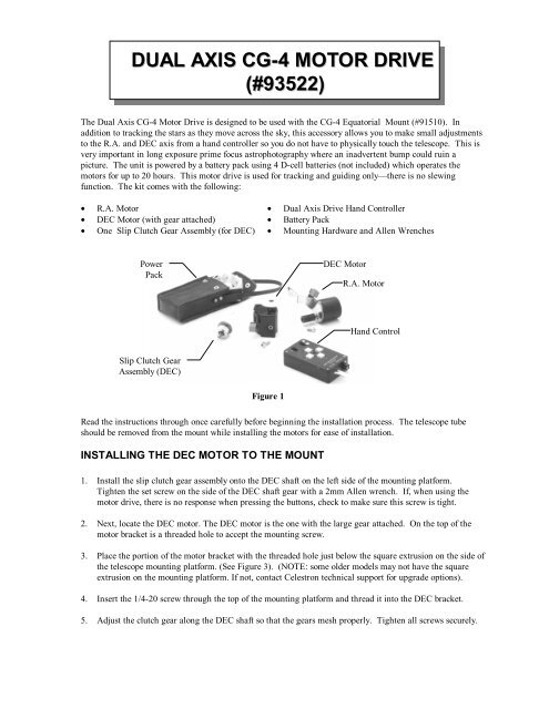
<strong>DUAL</strong> <strong>AXIS</strong> <strong>CG</strong>-4 <strong>MOTOR</strong> <strong>DRIVE</strong><br />
(<strong>#93522</strong>)<br />
The Dual Axis <strong>CG</strong>-4 Motor Drive is designed to be used with the <strong>CG</strong>-4 Equatorial Mount (#91510). In<br />
addition to tracking the stars as they move across the sky, this accessory allows you to make small adjustments<br />
to the R.A. and DEC axis from a hand controller so you do not have to physically touch the telescope. This is<br />
very important in long exposure prime focus astrophotography where an inadvertent bump could ruin a<br />
picture. The unit is powered by a battery pack using 4 D-cell batteries (not included) which operates the<br />
motors for up to 20 hours. This motor drive is used for tracking and guiding only—there is no slewing<br />
function. The kit comes with the following:<br />
• R.A. Motor • Dual Axis Drive Hand Controller<br />
• DEC Motor (with gear attached) • Battery Pack<br />
• One Slip Clutch Gear Assembly (for DEC) • Mounting Hardware and Allen Wrenches<br />
Power<br />
Pack<br />
DEC Motor<br />
R.A. Motor<br />
Hand Control<br />
Slip Clutch Gear<br />
Assembly (DEC)<br />
Figure 1<br />
Read the instructions through once carefully before beginning the installation process. The telescope tube<br />
should be removed from the mount while installing the motors for ease of installation.<br />
INSTALLING THE DEC <strong>MOTOR</strong> TO THE MOUNT<br />
1. Install the slip clutch gear assembly onto the DEC shaft on the left side of the mounting platform.<br />
Tighten the set screw on the side of the DEC shaft gear with a 2mm Allen wrench. If, when using the<br />
motor drive, there is no response when pressing the buttons, check to make sure this screw is tight.<br />
2. Next, locate the DEC motor. The DEC motor is the one with the large gear attached. On the top of the<br />
motor bracket is a threaded hole to accept the mounting screw.<br />
3. Place the portion of the motor bracket with the threaded hole just below the square extrusion on the side of<br />
the telescope mounting platform. (See Figure 3). (NOTE: some older models may not have the square<br />
extrusion on the mounting platform. If not, contact <strong>Celestron</strong> technical support for upgrade options).<br />
4. Insert the 1/4-20 screw through the top of the mounting platform and thread it into the DEC bracket.<br />
5. Adjust the clutch gear along the DEC shaft so that the gears mesh properly. Tighten all screws securely.
INSTALLING THE R.A. <strong>MOTOR</strong> TO THE MOUNT<br />
The R.A. motor will only install on the right side of the mount (i.e., when standing behind the mount where<br />
the R.A. setting circle is located).<br />
1. Locate the flexible motor coupling at the end of the R.A. motor.<br />
Flexible Motor<br />
Coupling<br />
R.A. Motor<br />
RJ-11 Jack<br />
Outlet<br />
DEC Motor<br />
RJ-11 Jack<br />
Outlet<br />
Slip Clutch<br />
Gear Assembly<br />
Mounting<br />
Bracket<br />
Figure 2<br />
Figure 3<br />
2. Attach the R.A. motor to the mount by placing the end of the motor coupling over the R.A. slow<br />
motion shaft. Make sure the flat side of the shaft is positioned under the coupling thumb screw<br />
before tightening.<br />
3. Use the R.A. slow motion knob to rotate the motor until the slotted hole on the metal bracket<br />
aligns with hole on the side of the polar housing. (See Figure 2).<br />
4. Insert the socket head screw through the slotted bracket and into the hole on the polar housing.<br />
Tighten down with an Allen wrench.<br />
POWERING THE <strong>DRIVE</strong><br />
The DA-<strong>CG</strong>-4 motor drive is powered by 4 D-cell size batteries (not included). This can operate the<br />
motor drive for up to 20 hours or more depending on the ambient temperature. To power the drive<br />
system:<br />
1. First, remove the battery compartment from its vinyl case.<br />
2. Insert batteries into the compartment so that they snap firmly into place.<br />
3. Put the battery compartment back inside its vinyl case.<br />
The DA-<strong>CG</strong>-4 Motor Drive has three cables that must be plugged in. Two cables attach to the drive<br />
motors and the other attaches to the hand control. To install the cables:<br />
1. Locate the phone jack cable coming from the hand control unit (marked “DEC”) and plug it into<br />
the jack outlet on the DEC motor. Likewise, plug the cable marked R.A. into the jack outlet on<br />
the R.A. motor.<br />
2. Plug the battery pack cable (stereo jack type) into the outlet on the hand control labeled "DC<br />
Power".
USING THE <strong>DRIVE</strong><br />
The hand control consists of two switches and four control buttons.<br />
• The switch marked "N/Off/S" turns the power to the motor on and off as well as changing the<br />
direction of the motors. Turn the switch to “N” to begin tracking for the northern hemisphere.<br />
Changing the switch to "S" will reverse the polarity of the motor to track stars in the southern<br />
hemisphere.<br />
• The switch marked “2X/4X/8X” determines the rate at which the motor will move when the hand<br />
controller buttons are pressed. 2X, twice the sidereal rate, is used for guiding on a star when<br />
doing long exposure astrophotography. 4X, four times sidereal, is used for centering objects in<br />
the eyepiece; and 8X, eight times sidereal, can be used for centering objects in the finderscope<br />
as well as the eyepiece.<br />
• The four push buttons control the motor drive direction. The “Up” and “Down” buttons control the<br />
telescope in declination (DEC). The “Left “ and “Right” buttons control the telescope in Right<br />
Ascension (RA). The direction for each button will be reversed when switched to the southern<br />
hemisphere position.<br />
The Declination motor can be disengaged in order to manually move the mount via the slow motion<br />
control knob. To override the motor, the lock on the clutch gear assembly must be loosened. This<br />
will allow the gear hub to rotate independently from the actual gear. For Declination, loosen the<br />
clutch wheel on the gear assembly and turn the slow motion control knob attached to the shaft of the<br />
clutch gear assembly. Tighten the clutch wheel to re-engage the tracking.<br />
Troubleshooting?<br />
A common problem with the DA-<strong>CG</strong>-4 motor drive on the <strong>CG</strong>-4 mount is the worm gears are<br />
sometimes fitted too tightly to the helical gears. This causes the motors to bind up. Conversely, the<br />
worm gear may fit too loosely, causing excess backlash in the motors. In either case the worm may<br />
need to be adjusted. The procedure and the assemblies are the same for the DEC and the R.A. The<br />
only difference is the location. The DEC worm assembly is located on the top of the mount. It is the<br />
box to which the DEC slow motion knob is attached. To recognize if the gears are meshing too<br />
tightly, turn the R.A. manual slow motion control. If it is noticeably hard to turn then it should be<br />
loosened. If you cannot tell, then the motor will let you know. It will either run or it won’t.<br />
To Adjust the Worm Gears:<br />
1. Remove the motor drive assembly.<br />
2. Locate the worm assembly on either the R.A. or Dec axis. This is the box to which the slow<br />
motion knobs are attached.<br />
3. Locate the 4 Allen head cap screws that hold the worm gear assembly in place. Two are located<br />
underneath the box with a set screw located in between. Two are located on the backside of the<br />
mount.<br />
4. Slightly loosen all four screws.<br />
5. Turn the center set screw on the underside about a quarter turn clockwise (to loosen the R.A.<br />
worm assembly) or a quarter turn counter-clockwise (to tighten the worm gear assembly if the<br />
backlash is too great).<br />
6. Tighten the four cap screws and try the worm gear.<br />
Note that if worm is loosened too much, then backlash between the gears can become a problem.<br />
You may need to tighten the worm assembly. This process of loosening then tightening the worm<br />
takes some trail and error, but once it is adjusted correctly, it won’t need any further adjustments.