
Create successful ePaper yourself
Turn your PDF publications into a flip-book with our unique Google optimized e-Paper software.
INTRODUCTION.......................................................................................................................................................................................................................4Warning.......................................................................................................................................................................................................... 4ASSEMBLY.................................................................................................................................................................................................................................6Setting up the Tripod...................................................................................................................................................................................... 6Attaching the Equatorial Mount ..................................................................................................................................................................... 7Attaching the Accessory Tray ........................................................................................................................................................................ 8Installing the Counterweight Bar.................................................................................................................................................................... 8Installing the Counterweight .......................................................................................................................................................................... 8Attaching the Hand Control Holder ............................................................................................................................................................... 9Attaching the Optical Tube to the Mount....................................................................................................................................................... 9Attaching the Visual Back............................................................................................................................................................................ 10Installing the Star Diagonal.......................................................................................................................................................................... 10Installing the Eyepiece ................................................................................................................................................................................. 10Installing the Finderscope ............................................................................................................................................................................ 11Installing the <strong>CGEM</strong> 1100 Finderscope ....................................................................................................................................................... 11Removing the Lens Cap ............................................................................................................................................................................... 13Moving the Telescope <strong>Manual</strong>ly.................................................................................................................................................................. 13Balancing the Mount in R.A......................................................................................................................................................................... 13Balancing the Mount in DEC ....................................................................................................................................................................... 14Adjusting the Mount .................................................................................................................................................................................... 14Adjusting the Mount in Altitude................................................................................................................................................................... 14Adjusting the Mount in Azimuth.................................................................................................................................................................. 15Powering the Telescope ............................................................................................................................................................................... 15HAND CONTROL....................................................................................................................................................................................................................16Hand Control Operation ............................................................................................................................................................................... 17Alignment Procedures.................................................................................................................................................................................. 17Startup Procedure......................................................................................................................................................................................... 18Two Star Align............................................................................................................................................................................................. 19East/West Filtering .............................................................................................................................................................................. 19Quick-Align ................................................................................................................................................................................................. 20Last Alignment............................................................................................................................................................................................. 21Re-Alignment............................................................................................................................................................................................... 21Object Catalog.............................................................................................................................................................................................. 21Selecting an Object....................................................................................................................................................................................... 21Slewing to an Object .................................................................................................................................................................................... 22Finding Planets............................................................................................................................................................................................. 22Tour Mode.................................................................................................................................................................................................... 22Constellation Tour........................................................................................................................................................................................ 22Direction Buttons.......................................................................................................................................................................................... 23Rate Button................................................................................................................................................................................................... 23Setup Procedures.......................................................................................................................................................................................... 23Tracking Mode .................................................................................................................................................................................... 23Tracking Rate ...................................................................................................................................................................................... 24Date/Time............................................................................................................................................................................................ 24User Defined Objects .......................................................................................................................................................................... 24Get RA/DEC ....................................................................................................................................................................................... 25Goto R.A/Dec...................................................................................................................................................................................... 25Identify ................................................................................................................................................................................................ 25Precise GoTo ................................................................................................................................................................................................ 25Scope Setup Features.................................................................................................................................................................................... 25Setup Time-Site................................................................................................................................................................................... 25Anti-backlash ...................................................................................................................................................................................... 26Filter Limits......................................................................................................................................................................................... 26Direction Buttons ................................................................................................................................................................................ 26Goto Approach .................................................................................................................................................................................... 26Autoguide Rates .................................................................................................................................................................................. 27OTA Orientation.................................................................................................................................................................................. 27Meridian .............................................................................................................................................................................................. 27Mount Settings .................................................................................................................................................................................... 27RA Limits............................................................................................................................................................................................ 28Utility Features............................................................................................................................................................................................. 28Calibrate Mount................................................................................................................................................................................... 282
Home Position ..................................................................................................................................................................................... 29Light Control ....................................................................................................................................................................................... 29Factory Settings................................................................................................................................................................................... 29Version ................................................................................................................................................................................................ 29Get Axis Position................................................................................................................................................................................. 29Goto Axis Position .............................................................................................................................................................................. 29Hibernate ............................................................................................................................................................................................. 29Sun Menu ............................................................................................................................................................................................ 29Scrolling Menu.................................................................................................................................................................................... 30Set Mount Position .............................................................................................................................................................................. 30Set Mount Position....................................................................................................................................................................................... 30Turn On/Off GPS ................................................................................................................................................................................ 30Turn On/Off RTC................................................................................................................................................................................ 30Periodic Error Correction .................................................................................................................................................................... 30TELESCOPE BASICS..............................................................................................................................................................................................................32Image Orientation......................................................................................................................................................................................... 32Focusing ....................................................................................................................................................................................................... 33Calculating Magnification ............................................................................................................................................................................ 33Determining Field of View........................................................................................................................................................................... 33General Observing Hints .............................................................................................................................................................................. 34ASTRONOMY BASICS ...........................................................................................................................................................................................................35The Celestial Coordinate System.................................................................................................................................................................. 35Motion of the Stars ....................................................................................................................................................................................... 36Polar Aligning the Mount............................................................................................................................................................................. 37Polar Align .......................................................................................................................................................................................... 37Finding the North Celestial Pole................................................................................................................................................................... 39CELESTIAL OBSERVING .....................................................................................................................................................................................................40Observing the Moon..................................................................................................................................................................................... 40Lunar Observing Hints ................................................................................................................................................................................. 40Observing the Planets ................................................................................................................................................................................... 40Observing the Sun ........................................................................................................................................................................................ 40Solar Observing Hints .................................................................................................................................................................................. 41Observing Deep Sky Objects........................................................................................................................................................................ 41Seeing Conditions......................................................................................................................................................................................... 41Transparency ................................................................................................................................................................................................ 41Sky Illumination ........................................................................................................................................................................................... 41Seeing........................................................................................................................................................................................................... 41ASTROPHOTOGRAPHY........................................................................................................................................................................................................43Short Exposure Prime Focus Photography ................................................................................................................................................... 43Eyepiece Projection...................................................................................................................................................................................... 44Long Exposure Prime Focus Photography ................................................................................................................................................... 46Periodic Error Correction (PEC) .................................................................................................................................................................. 47Using Periodic Error Correction................................................................................................................................................................... 47Terrestrial Photography ................................................................................................................................................................................ 48Metering ....................................................................................................................................................................................................... 48Reducing Vibration ...................................................................................................................................................................................... 48CCD Imaging ............................................................................................................................................................................................... 49Auto Guiding................................................................................................................................................................................................ 49TELESCOPE MAINTENANCE..............................................................................................................................................................................................50Care and Cleaning of the Optics................................................................................................................................................................... 50Collimation................................................................................................................................................................................................... 50OPTIONAL ACCESSORIES .................................................................................................................................................................................................53APPENDIX A – TECHNICAL SPECIFICATIONS............................................................................................................................................................56APPENDIX B – GLOSSARY OF TERMS............................................................................................................................................................................57APPENDIX C – RS-232 CONNECTION................................................................................................................................................................................60APPENDIX D – TIME ZONE MAP........................................................................................................................................................................................62SKY MAPS................................................................................................................................................................................................................................643
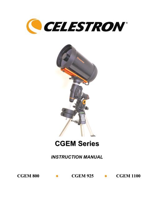
Congratulations on your purchase of the <strong>Celestron</strong> <strong>CGEM</strong> <strong>Series</strong> telescope! The <strong>CGEM</strong> <strong>Series</strong> is made of the highest quality materials toensure stability and durability. All this adds up to a telescope that gives you a lifetime of pleasure with a minimal amount of maintenance.Furthermore, your <strong>Celestron</strong> telescope is versatile — it will grow as your interest grows.The <strong>CGEM</strong> <strong>Series</strong> ushers in the next generation of computer automated telescopes. The <strong>CGEM</strong> series continues in this proud traditioncombining large aperture optics with the sophistication and ease of use of our computerized GoTo mount.If you are new to astronomy, you may wish to start off by using the built-in Sky Tour feature, which commands the telescopes to find themost interesting objects in the sky and automatically slews to each one. Or if you are an experienced amateur, you will appreciate thecomprehensive database of over 40,000 objects, including customized lists of all the best deep-sky objects, bright double stars and variablestars. No matter your level of experience, the <strong>CGEM</strong> <strong>Series</strong> telescopes will unfold for you and your friends all the wonders of the Universe.Some of the many standard features of the telescope include:• Fully enclosed optical encoders for position location.• Ergonomically designed mount that disassembles into compact and portable pieces.• Database filter limits for creating custom object lists.• Storage for programmable user defined objects; andMany other high performance features!The <strong>CGEM</strong> deluxe features combine with <strong>Celestron</strong>’s legendary Schmidt-Cassegrain optical system to give amateur astronomers the mostsophisticated and easy to use telescopes available on the market today.Take time to read through this manual before embarking on your journey through the Universe. It may take a few observing sessions tobecome familiar with your telescope, so you should keep this manual handy until you have fully mastered your telescope’s operation. Thehand control has built-in instructions to guide you through all the alignment procedures needed to have the telescope up and running inminutes. Use this manual in conjunction with the on-screen instructions provided by the hand control. The manual gives detailedinformation regarding each step as well as needed reference material and helpful hints guaranteed to make your observing experience assimple and pleasurable as possible.Your telescope is designed to give you years of fun and rewarding observations. However, there are a few things to consider before usingyour telescope that will ensure your safety and protect your equipment.WarningNever look directly at the sun with the naked eye or with a telescope (unless you have the proper solarfilter). Permanent and irreversible eye damage may result.Never use your telescope to project an image of the sun onto any surface. Internal heat build-up can damage the telescope and anyaccessories attached to it.Never use an eyepiece solar filter or a Herschel wedge. Internal heat build-up inside the telescope can cause these devices to crack orbreak, allowing unfiltered sunlight to pass through to the eye.Never leave the telescope unsupervised, either when children are present or adults who may not be familiar with the correct operatingprocedures of your telescope.4
ASFigure 2.2 – <strong>CGEM</strong>(<strong>CGEM</strong> 1100 Shown)12111102E893D456CBA71 Optical Tube 7 Tripod Center Leg Brace/Accessory Tray2 Telescope Mounting Platform 8 Counterweight(s)3 Equatorial Mount 9 Counterweight Bar4 Latitude Adjustment Knob 10 Azimuth Adjustment Knob5 Hand Control 11 Dovetail Mounting Bar6 Tripod 12 Schmidt Corrector LensCONTROL PANEL C Hand Control PortA On/Off Switch D Aux PortB 12v Input Jack E Autoguider Port5
This section covers the assembly instructions for your <strong>Celestron</strong> Telescope. Your telescope should be set up indoor the firsttime so that it is easy to identify the various parts and familiarize yourself with the correct assembly procedure beforeattempting it outdoor.Diameter#11097 #11098 #11099<strong>CGEM</strong> 800 <strong>CGEM</strong> 925 <strong>CGEM</strong> 1100203mm (8") Schmidt-Cassegrain235mm (9.25") Schmidt-Cassegrain280mm (11") Schmidt-CassegrainFocal Length 2032mm F/10 2350mm F/10 2800mm F/10Eyepiece 25mm - 1.25" (81x) 25mm - 1.25" (94x) 40mm - 1.25" (70x)Finderscope 6x30 6x30 9x50Diagonal 90° - 1.25" 90° - 1.25" 90° - 1.25"Mount <strong>CGEM</strong> Equatorial <strong>CGEM</strong> Equatorial <strong>CGEM</strong> EquatorialTripod 2" Stainless Steel 2" Stainless Steel 2" Stainless SteelSoftwareNexRemote TelescopeControl SoftwareNexRemote TelescopeControl SoftwareNexRemote TelescopeControl SoftwareCounterweights 1-17lb 1-17lb; 1-11lb 2-17lbThe <strong>Celestron</strong> <strong>CGEM</strong> <strong>Series</strong> telescopes are shipped in three main boxes. In separate boxes are the following:Optical Tube Assembly and Standard AccessoriesEquatorial Mount with Hand Control, and Counterweight BarTripod plus one CounterweightAdditional Counterweights (11098 & 11099 only)Remove all the pieces from their respective boxes and place on a flat, clear work area. A large floor space is ideal. Whensetting up your <strong>Celestron</strong> telescope you must start with the tripod and work up from there. These instructions are laid out inthe order each task must be performed.Setting up the TripodThe <strong>CGEM</strong> tripod comes with an all metal center leg brace / accessory tray to give rock solid support to the mount.The tripod comes fully assembled with a metal plate, called the tripod head, that holds the legs together at the top. Inaddition, there is a central rod that extends down from the tripod head that attaches the equatorial mount to the tripod. To setup the tripod:1. Stand the tripod upright and pull the tripod legs apart until each leg is fully extended. The tripod will now stand by itself.Once the tripod is set up, you can adjust the height at which it stands.2. Loosen the lever on the leg clamp so that the tripod leg can be adjusted.3. Slide the center portion of the tripod leg away from the tripod head until it is at the desired height.4. Tighten the levers on each leg clamp to hold the legs in place.Attaching the Azimuth Adjustment KnobsTo ensure safe shipment of your <strong>CGEM</strong> mount, the Azimuth Adjustment Knobs have been removed from the mount and willneed to be attached.6
Before securing the mount to the tripod as shown in Fig. 2-3:1. Locate the Azimuth Adjustment Knobs from the box containing the <strong>CGEM</strong> mount.2. Thread one knob into each of the holes located on either side of the mount.3. Only thread the knobs about half way in, leaving enough space for the tripod Alignment Peg which will need to fitbetween the screw tips.Figure 2-2Attaching the Equatorial MountThe equatorial mount allows you to tilt the telescope’s axis of rotationso that you can track the stars as they move across the sky. The<strong>CGEM</strong> mount is a German equatorial mount that attaches to the tripodhead. On one side of the tripod head there is a metal alignment pegfor aligning the mount. This side of the tripod will face north whensetting up for an astronomical observing session. To attach theequatorial head:1. Locate the azimuth adjustment screws on the equatorial mount.2. Retract the screws so they do not extend into the azimuth housing onthe mount. Do NOT remove the screws since they are needed laterfor polar alignment.3. Hold the equatorial mount over the tripod head so that the azimuthhousing is above the metal peg.4. Place the equatorial mount on the tripod head so that the two areflush.5. Tighten the knob (attached to the central rod) on the underside of thetripod head to hold the equatorial mount firmly in place.EquatorialMountMountingKnobPoint TowardsNorthAzimuthAdjustmentScrewsAlignmentPegFigure 2-37
Attaching the Accessory Tray1. Slide the accessory tray over the central rod so that each arm of the tray is pushing against the inside of the tripod legs.2. Thread the accessory tray knob on to the central rod and tighten.Installing the Counterweight BarTo properly balance the telescope, the mount comeswith a counterweight bar and at least onecounterweight (depending on model). To install thecounterweight bar:1. Locate the counterweight bar locking nut from the boxcontaining the <strong>CGEM</strong> mount (see Fig 2-5).2. Thread the counterweight bar through the rounded endof locking nut until the threads pass all the waythrough and the locking nut can go no further.Mounting KnobCentral RodAccessory TrayAccessoryTray Knob3. Locate the opening in the equatorial mount on theDEC axisFigure 2-44. Thread the counterweight bar into the opening until tight.5. Tighten the counterweight bar lock nut fully for added support.Once the bar is securely in place you are ready to attach the counterweight.Since the fully assembled telescope can be quite heavy, position the mount so that the polar axis is pointing towardsnorth before the tube assembly and counterweights are attached. This will make the polar alignment procedure mucheasier.Installing the CounterweightDepending on which telescope model you have, you will receive either one, two or three counterweights. To install thecounterweight(s):Counterweight Bar1. Orient the mount so that the counterweight bar points toward the ground .Locking Nut2. Remove the counterweight safety screw on the end of the counterweight bar (i.e.,opposite the end that attaches to the mount).CounterweightBar3. Loosen the locking screw on the side of the counterweight.Locking Screw4. Slide the counterweight onto the shaft (see Figure 2-5).5. Tighten the locking screw on the side of the weight to hold the counterweight inplace.6. Replace the counterweight safety screw.CounterweightSafety ScrewFigure 2-5 – Mount shown with twocounterweights (<strong>CGEM</strong> 925 & 1100)8
Attaching the Hand Control HolderThe telescope comes with a hand control holder to place the computerized hand control. The hand control holder comes in twopieces: the leg clamp that snaps around the tripod leg and the holder which attaches to the leg clamp. To attach the handcontrol holder:1. Place the leg clamp up against one of the tripod legs andpress firmly until the clamp wraps around the leg.2. Slide the back of the hand control holder downward intothe channel on the front of the legs clamp (see Fig 2-6)until it snaps into place.Hand ControlHolderAttaching the Optical Tube to theMountThe telescope attaches to the mount via a dovetail slide bar whichFigure 2-6is mounted along the bottom of the telescope tube. Before youattach the optical tube, make sure that the declination and right ascension clutch knobs are tight (see Figure 2-13) andthe counterweight(s) are securely installed. This will ensure that the mount does not move suddenly while attaching thetelescope. To mount the telescope tube:1. Loosen the mounting screw on the side of the telescope mounting platform. This allows you to slide the dovetail baronto the mount.2. Remove the safety screw located at the front of the dovetail bar.3. Slide the dovetail bar on the telescope tube into the mounting platform of the mount. Slide the telescope so that theback of the dovetail bar is close to the back of the mounting platform.4. Tighten the mounting screw on the side of the mounting platform to hold the telescope in place.Now that the optical tube is securely in place, the visual accessories can now be attached to the telescope.Safety ScrewDovetail BarTelescope Mounting ScrewFigure 2-79
Attaching the Visual BackThe visual back is the accessory that allows you to attach all visual accessories to the telescope. The telescope optical tubescome with the visual back installed. If it is not already on the tube it can be attached as follows:1. Remove the rubber cover on the rear cell.2. Place the knurled slip ring on the visual back over the threads on the rear cell (Fig 2-8).3. Hold the visual back with the set screw in a convenient position and rotate the knurled slip ring clockwise until tight.Once this is done, you are ready to attach other accessories, such as eyepieces, diagonal prisms, etc.If you want to remove the visual back, rotate the slip ring counterclockwise until it is free of the rear cell.Installing the Star DiagonalThe star diagonal is a prism that diverts the light at a right angle to the light path of the telescope. This allows you to observein positions that are physically more comfortable than if you lookedstraight through. To attach the star diagonal onto the optical tube:Eyepiece1. Turn the set screw on the visual back until its tip no longer extends into(i.e., obstructs) the inner diameter of the visual back.2. Slide the chrome portion of the star diagonal into the visual back.3. Tighten the set screw on the visual back to hold the star diagonal in place.If you wish to change the orientation of the star diagonal, loosen the setscrew on the visual back until the star diagonal rotates freely. Rotate thediagonal to the desired position and tighten the set screw.Installing the EyepieceStar DiagonalVisual BackFigure 2-8The eyepiece, or ocular, is an optical element that magnifies the image focused by the telescope. The eyepiece fits into eitherthe visual back directly or the star diagonal. To install an eyepiece:1. Loosen the set screw on the star diagonal until the tip no longer extends into the inner diameter of the eyepiece end ofthe diagonal.2. Slide the chrome portion of the eyepiece into the star diagonal.3. Tighten the set screw on the star diagonal to hold the eyepiece in place.To remove the eyepiece, loosen the set screw on the star diagonal and slide the eyepiece out. You can replace it with anothereyepiece (purchased separately).Eyepieces are commonly referred to by focal length and barrel diameter. The focal length of each eyepiece is printed on theeyepiece barrel. The longer the focal length (i.e., the larger the number) the lower the eyepiece power and the shorter the focallength (i.e., the smaller the number) the higher the magnification. Generally, you will use low-to-moderate power whenviewing. For more information on how to determine power, see the section on “Calculating Magnification.”10
Installing the FinderscopeThe <strong>CGEM</strong> 800 and 925 telescopes come with a 6x30 finderscope used to help you locate and center objects in the main fieldof your telescope. To accomplish this, the finder has a built-in cross-hair reticle that shows the optical center of thefinderscope. The <strong>CGEM</strong> 1100 comes with a 9x50 finderscope.Start by removing the finder and hardware from the plastic wrapper. Included are the following:• Finderscope• Finder Bracket• Rubber O-ring• Three Nylon Thumbscrews (10-24x1/2")• Two Phillips Head Screws (8-32x1/2")To install the finderscope:1. Attach the bracket to the optical tube. To do this, place the curvedportion of the bracket with the slot over the two holes in the rearcell. The bracket should be oriented so that the rings that hold thefinder are over the telescope tube, not the rear cell (see Fig 2-9).Start threading the screws in by hand and tighten fully with anAllen wrench.FinderscopeNylonAdjustmentScrew2. Partially thread-in the three nylon thumbscrews that hold the finderin place inside the bracket. Tighten the screws until the nylonheads are flush with the inner diameter of the bracket ring. DoNOT thread them in completely or they will interfere with theplacement of the finder. (Having the screws in place when thefinder is installed will be easier than trying to insert the screwsafter the finder has been installed.)Figure 2-93. Slide the rubber O-ring over the back of the finder (it will NOT fit over theobjective end of the finder). It may need to be stretched a little. Once on the main body of the finder, slide it up aboutone inch from the end of the finder.4. Rotate the finder until one cross hair is parallel to the R.A. axis and the other is parallel to the DEC axis.5. Slide the eyepiece end of the finder into the front of the bracket.6. Slightly tighten the three nylon thumbscrews on the front ring of the bracket to hold the finder in place.7. Once on, push the finder back until the O-ring is snug inside the back ring of the finder bracket.8. Hand tighten the three nylon tipped thumbscrews until snug.Installing the <strong>CGEM</strong> 1100 FinderscopeFigure 2-11Finder BracketRear CellThe <strong>CGEM</strong> 1100 telescope comes with a 9x50 finderscope. The specifications for a finderscope stand for the magnification and theaperture, in millimeters, of the scope. So, a 9x50 finder magnifies objects eight times and has a 50mm objective lens.Finderscope InstallationThe finderscope must first be mounted in the included quick-release bracket then attached to the rear cell of the telescope.To install the finderscope:1. Locate the finderscope mounting bracket attached to the bottom portion of the finder bracket. Loosen the two thumbscrews to slide the mounting bracket from the finderscope bracket.2. Find the two holes in the rear cell of the telescope on the top left, when looking from the back of the tube.11
3. Place the mounting bracket over the two holes of the rear cell as shown in the figure 2-10.4. Insert the screws through the bracket and into the rear cell.Figure 2-10WARNING: If you remove the mounting bracket, do not completely thread the screws back into the rear cell of the telescope.The screws may be long enough to obstruct the movement of, and possibly damage the primary mirror.With the bracket firmly attached to the telescope, you areready to attach the finder to the bracket.1. Slide the O-Ring over the back of the finderscopeand position it on the tube toward the objectiveend of the finderscope.PivotScrewAlignment ScrewsQuick releaseScrews2. Slide the eyepiece end of the finderscope into thefront ring of the bracket (the front ring is the onewithout the adjustment screws), then through theback ring. It may be necessary to push down thespring loaded pivot screw so that the finder willpass through the back ring (see figure 2-11)Figure 2-113. Push the finder back until the O-Ring is snug inside the front ring of the finder bracket.4. Hand tighten the two alignment thumb screws until they make contact with the finderscope.Aligning the FinderscopeFigure 2-12The finderscope bracket comes in two pieces; the mounting bracket (left) and the finder bracket (right)The finderscope is adjusted using two adjustment screws, located on the top and on the right (when looking though the finder)of the finder bracket and a spring loaded pivot screw (located on the left side of the bracket). This allows you to turn the topadjustment screw to move the finderscope up and down, and turn the right adjustment screw to move the finderscope right toleft. The spring loaded pivot screw puts constant pressure on the finder so that the adjustment screws are always makingcontact with the finder.To make the alignment process a little easier, you should perform this task in the daytime when it is easier to locate objects inthe telescope without the finder. To align the finder:1. Choose a conspicuous object that is in excess of one mile away. This will eliminate any possible parallax effectbetween the telescope and the finder.12
2. Point your telescope at the object you selected and center it in the main optics of the telescope.3. Lock the azimuth and altitude clamps to hold the telescope in place.4. Check the finder to see where the object is located in the field of view.5. Adjust the thumb screws on the finder bracket, until the cross hairs are centered on the target.Removing the Lens CapThe 8, 9.25 and 11" lens cap utilizes a bayonet-type lockingmechanism to hold it in place. To remove the lens cap, hold thecover firmly and rotate the outer edge 1/2” counterclockwise andpull off.DeclinationLockMoving the Telescope <strong>Manual</strong>lyIn order to properly balance your telescope, you will need tomove your telescope manually at various portions of the sky toobserve different objects. To make rough adjustments, loosen theR.A. and DEC clutch knobs slightly and move the telescope inthe desired direction.Right Ascension(RA) LockFigure 2-13Both the R.A. and DEC axis have lock levers to clutch down eachaxis of the telescope. To loosen the clutches on the telescope, rotate the lock levers counterclockwise.Balancing the Mount in R.A.To eliminate undue stress on the mount, the telescope should be properly balanced around the polar axis. Proper balancing iscrucial for accurate tracking. To balance the mount:1. Verify that the telescope is securely attached to the telescope mounting platform.2. Loosen the R.A. lock lever and position the telescope off to one side of the mount. The counterweight bar willextend horizontally on the opposite side of the mount.3. Release the telescope — GRADUALLY — to see which way the telescope “rolls.”4. Loosen the set screws on the side of the counterweight so it can be moved the length of the counterweight bar.5. Move the counterweight to a point where it balances the telescope (i.e., the telescope remains stationary when theR.A. clutch knobs are loose).6. Tighten the screw on the counterweight to hold it in place.While the above instructions describe a perfect balance arrangement, there should be a SLIGHT imbalance to ensure the bestpossible tracking. When the scope is on the west side of the mount the counterweight should be slightly imbalanced to thecounterweight bar side. And when the tube is on the east side of the mount there should be a slight imbalance toward thetelescope side. This is done so that the worm gear is pushing against a slight load. The amount of the imbalance is very slight.When taking astrophotographs, this balance process can be done for the specific area at which the telescope is pointing tofurther optimize tracking accuracy.13
Figure 2-14Balancing the Mount in DECAlthough the telescope does not track in declination, the telescope should also be balanced in this axis to prevent any suddenmotions when the DEC lock lever is loose. To balance the telescope in DEC:1. Loosen the R.A. clutch lock lever and rotate the telescope so that it is on one side of the mount (i.e., as describedin the previous section on “Balancing the Mount in R.A.”).2. Tighten the R.A. lock lever to hold the telescope in place.3. Loosen the DEC clutch lock lever and rotate the telescope until the tube is parallel to the ground.4. Release the tube — GRADUALLY — to see which way it rotates around the declination axis. DO NOT LETGO OF THE TELESCOPE TUBE COMPLETELY!5. Slightly loosen the knobs that holds the telescope to the mounting platform and slide the telescope either forwardor backward until it remains stationary when the DEC clutch is loose. Do NOT let go of the telescope tube whilethe knob on the mounting platform is loose. It may be necessary to rotate the telescope so that the counterweightbar is pointing down before loosening the mounting platform screw.6. Tighten the knobs on the telescope mounting platform to hold the telescope in place.Like R.A. balance, these are general balance instructions and will reduce undue stress on the mount. When takingastrophotographs, this balance process should be done for the specific area at which the telescope is pointing.Adjusting the MountIn order for a motor drive to track accurately, the telescope’s axis of rotation must be parallel to the Earth’s axis of rotation, aprocess known as polar alignment. Polar alignment is achieved NOT by moving the telescope in R.A. or DEC, but byadjusting the mount vertically, which is called altitude, and horizontally, which is called azimuth. This section simply coversthe correct movement of the telescope during the polar alignment process. The actual process of polar alignment, that ismaking the telescope’s axis of rotation parallel to the Earth’s, is described later in this manual in the section on “PolarAlignment.”Adjusting the Mount in Altitude• To increase (raise) the latitude of the polar axis,turn the rear latitude adjustment knob andloosen the front screw (if necessary).• To decrease (lower) the latitude of the polaraxis, turn the rear latitude adjustment knob andtighten the front screw (if necessary).Rear LatitudeAdjustmentKnobFrontLatitudeAdjustmentScrewAzimuthAdjustmentKnobFigure 2-1514
The latitude adjustment on the mount has a range from approximately 15° to 70°.It is best to always make final adjustments in latitude by moving the mount against gravity (i.e. using the rear latitudeadjustment screw to raise the mount).Adjusting the Mount in AzimuthFor rough adjustments in azimuth, simply pick up the telescope and tripod and move it side to side until it is roughly pointingtowards north. For fine adjustments in azimuth:1. Turn the azimuth adjustment knobs located on either side of the azimuth housing (see Fig 2-15). While standing behind thetelescope, the knobs are on the front of the mount.• Turning the right adjustment knob clockwise moves the mount toward the right.• Turning the left adjustment knob clockwise moves the mount to the left.Both screws push off of the peg on the tripod head, which means you may have to loosen one screw while tightening the other.The screw that holds the equatorial mount to the tripod may have to be loosened slightly.Keep in mind that adjusting the mount is done during the polar alignment process only. Once polar aligned, the mount mustNOT be moved. Pointing the telescope is done by moving the mount in right ascension and declination, as described earlier inthis manual.Powering the TelescopeThe telescope mount can be powered by the supplied car battery adapter or optional 12v AC adapter. Use only adapterssupplied by <strong>Celestron</strong>. Using any other adapter may damage the electronics or cause the telescope not to operate properly, andwill void your manufacturer's warranty.1. To power the telescope with the car battery adapter (or 12v AC adapter), simply plug the round post into the 12voutlet on the electronic panel and plug the other end into your cars cigarette lighter outlet or portable power supply(see Optional Accessories).2. Turn on the power to the telescope by flipping the switch, located on the electronics panel, to the "On" position.15
All <strong>Celestron</strong> computerized telescope come with a hand control designed to give you instant access to all the functions thatyour telescope has to offer. With automatic slewing to over 40,000 objects, and common sense menu descriptions, even abeginner can master its variety of features in just a few observing sessions. Below is a brief description of the individualcomponents of the computerized hand controller:1. Liquid Crystal Display (LCD) Window: Has a dual-line, 16 character display screen that is backlit forcomfortable viewing of telescope information and scrolling text.2. Align: Instructs the telescope to use a selected star or object as an alignment position.3. Direction Keys: Allows complete control of the telescope in any direction. Use the direction keys to move thetelescope to the initial alignment stars or for centering objects in the eyepiece.172839410511612Figure 3-1The Hand Control16
4. Catalog Keys: The hand control has keys on the hand control to allow direct access to each of the catalogs in itsdatabase. The hand control contains the following catalogs in its database:Messier – Complete list of all Messier objects.NGC – Complete list of all the deep-sky objects in the Revised New General Catalog.Caldwell – A combination of the best NGC and IC objects.Planets - All 8 planets in our Solar System plus the Moon.Stars – A compiled list of the brightest stars from the SAO catalog.List – For quick access, all of the best and most popular objects in the telescope's database have been brokendown into lists based on their type and/or common name:Named StarsNamed ObjectsDouble StarsVariable StarsAsterismsCCD ObjectsIC ObjectsAbell ObjectsConstellationCommon name listing of the brightest stars in thesky.Alphabetical listing of over 50 of the most populardeep sky objects.Numeric-alphabetical listing of the most visuallystunning double, triple and quadruple stars in thesky.Select list of the brightest variable stars with theshortest period of changing magnitude.A unique list of some of the most recognizable starpatterns in the sky.A custom list of many interesting galaxy pairs, triosand clusters that are well suited for CCD imaging.A complete list of all the Index Catalog deep-skyobjects.A custom list of the Abell Catalog deep-skygalaxies.A complete list of all 88 constellations.5. Info: Displays coordinates and useful information about objects selected from the telescope database.6. Tour: Activates the tour mode, which seeks out all the best objects for the current date and time, and automaticallyslews the telescope to those objects.7. Enter: Pressing Enter allows you to select any of the telescope's functions and accept entered parameters.8. Undo: Undo will take you out of the current menu and display the previous level of the menu path. Press Undorepeatedly to get back to a main menu or use it to erase data entered by mistake.9. Menu: Displays the many setup and utilities functions such as tracking rates and user defined objects and manyothers.10. Scroll Keys: Used to scroll up and down within any of the menu lists. A double-arrow will appear on the right side ofthe LCD when there are sub-menus below the displayed menu. Using these keys will scroll through those sub-menus.11. Rate: Instantly changes the rate of speed of the motors when the direction buttons are pressed.12. RS-232 Jack: Allows you to interface with a computer and control the telescope remotely.Hand Control OperationThis section describes the basic hand control procedures needed to operate all <strong>Celestron</strong> computerized telescopes. Theseprocedures are grouped into three categories: Alignment, Setup and Utilities. The alignment section deals with the initialtelescope alignment as well as finding objects in the sky; the setup section discusses changing parameters such as trackingmode and tracking rate; finally, the last section reviews all of the utilities functions such as calibrating your mount, polaralignment and backlash compensation.Alignment ProceduresIn order for the telescope to accurately point to objects in the sky, it must first be aligned with known positions (stars) in thesky. With this information, the telescope can create a model of the sky, which it uses to locate any object with knowncoordinates. There are many ways to align your telescope with the sky depending on what information the user is able toprovide: Two Star Align uses the entered time/location information and allows the user to select which two alignment stars17
the telescope will automatically slew to. One Star Align uses the same time/location information but only uses one star foralignment. Solar System Align will display a list of visible daytime objects (planets and the moon) available to align thetelescope. Quick-Align will ask you to input all the same information as you would for the Auto Align procedure. However,instead of slewing to the alignment stars for centering and alignment, the telescope bypasses this step and simply models thesky based on the information given. Finally, Last Alignment restores your last saved star alignment and switch position.Last Alignment also serves as a good safeguard in case the telescope should lose power.Startup ProcedureBefore any of the described alignments are performed, the telescope mount needs to be positioned so that the index marks arealigned on both the right ascension and declination axes. (see Fig 3-2).Once the index position has been set, the hand controlwill display the last entered date and time informationstored in the hand control.1. Press ENTER to begin the alignment process.2. The hand control will ask the user to set themount to its index position. Move the telescopemount, either manually or with the hand control,so that the index marked in both R.A. and Decare aligned (see Fig 3-2). Press Enter tocontinue.The hand control will then display thelast entered local time, time zone anddate.IndexMarksUse the Up/Down keys (10) to view theFigure 3-2 - Declination Index Marks and Right Ascension (RA) Index Markscurrent parameters.Press ENTER to accept the current parameters.Press UNDO to enter current date, time and location information into the hand control. The followinginformation will be displayed:Location - The hand control will display a list of cities to choose from. Choose the city from the database that isclosest to your current observing site. The city you choose will be remembered in the hand controls memory so thatit will be automatically displayed the next time an alignment is done. Alternatively, if you know the exact longitudeand latitude of your observing site, it can be entered directly into the hand control and remembered for future use aswell. To choose a location city: Use the Up and Down scroll keys to choose between City Database and Custom Site. City Database willallow you to select the closest city to your observing site from a list of either international or U.S. location.Custom Site allows you to enter the exact longitude and latitude of your observing site. Select City Database andpress ENTER. The hand control will allow you to choose from either U.S. or international locations. For a listing of U.S.locations by state and then by city, press ENTER while United States is displayed. For internationallocations, use the Up or Down scroll key to select International and press ENTER. Use the Up and Down Scroll buttons to choose your current state (or country if International locations wasselected) from the alphabetical listing and press ENTER. Use the Up and Down Scroll buttons to choose the closest city to your location from the displayed list andpress ENTER.Time - Enter the current local time for your area. You can enter either the local time (i.e. 08:00), or you can entermilitary time (i.e. 20:00 ). Select PM or AM. If military time was entered, the hand control will bypass this step. Choose between Standard time or Daylight Savings time. Use the Up and Down scroll buttons (10) to togglebetween options.18
Select the time zone that you are observing from. Again, use the Up and Down buttons (10) to scroll throughthe choices. Refer to Time Zone map in Appendix for more information.Date - Enter the month, day and year of your observing session.Updating Your Location - Since you may not need to update your observing location as often as the date and time, itis not displayed each time you update the date and time. To update your city, press UNDO at any time when updatingyour date and time. Continue to press UNDO to change the state, country or to add longitude/latitude coordinates.Select one of the alignment methods as described below.Note: If incorrect information is entered into the hand control, the UNDO button acts like a back space button allowing theuser to re-enter the correct data.Two Star AlignTwo-Star Align allows the user to select two stars on which to align the telescope. To align your telescope using the Two-StarAlign method:1. Select Two-Star Align from the alignment choices given. Based on the date and time information entered, the handcontrol will automatically select and display a bright star that is above the horizon. Press ENTER to select this star as your first alignment star. If for some reason the chosen star is not visible (perhaps behind a tree or building) press UNDO to have thehand control automatically select the next brightest star.Or you can use the Up/Down keys to browse the entire Named Star list and select any one of over two hundredalignment stars.2. Once the telescope is finished slewing to your first alignment star, the display will ask you to use the arrow buttons toalign the selected star with the cross hairs in the center of the finderscope. When centered in the finder, press ENTER.3. The display will then instruct you to center the star in the field of view of the eyepiece. When the star is centered,press ALIGN to accept this star as your first alignment star.4. After the first alignment star has been entered the hand control will automaticallyselect a second alignment star and have you repeat this procedure for that star.East/West (E/W) FilteringWhen the telescope has been aligned on both stars the display will ask you if you wishto add additional calibration stars. Calibration stars are used to improve the pointingaccuracy of your telescope by compensating for subtle opto-mechanicalmisalignments between the telescope optics and the mount. Therefore it is usually agood idea to add at least one additional calibration star to improve the telescope’sall-sky pointing accuracy.5. Press ENTER to select a calibration star. Select a star the same way you did withthe first two alignments stars and pres ENTER. You will notice that all thecalibration stars displayed are located on the opposite side of the side of the sky(Meridian) as the original alignment stars. This is essential for an accuratecalibration of the mount.Finally you can chose to continue to add additional calibration stars or Press UNDO tocomplete the alignment.Tips for adding calibration stars:Although for casual observing it is not necessary to add calibration stars, itis recommended that you add as many as three calibration stars for optimalpoint accuracy.In order to ensure the bestpossible full sky pointingaccuracy, your computerizedtelescope automatically filtersand chooses its initialalignment stars so that the firsttwo alignment stars are locatedon one side of the Meridianand any calibration stars are onthe opposite side of theMeridian, as indicated by the"W" or "E" displayed in theupper-right corner of the LCD.East/West filtering can bechanged simply by pressingthe MENU button at any timeduring the alignment process.Calibration stars that are near the equator offer the best results than stars near the poles.Although it is not be necessary to use calibration stars if the telescope mount has not been moved since itsoriginal alignment/calibration, it may be necessary to recalibrate the telescope if the optical tube has beenremoved for any reason.19
One Star AlignOne-Star Alignment works much the same way as Two-Star Align but usesonly a single star in the sky for alignment. This method of alignment is not asaccurate as the two-star alignment and is recommended only for telescopesthat are permanently and accurately polar aligned.Solar System AlignSolar System Align is designed to provide excellent tracking and GoToperformance by using solar system objects (Sun, Moon and planets) to alignthe telescope with the sky. Solar System Align is a great way to align yourtelescope for daytime viewing as well as a quick way to align the telescope fornighttime observing.Never look directly at the sun with the naked eye or with a telescope(unless you have the proper solar filter). Permanent and irreversibleeye damage may result.1. Select Solar System Align from the alignment options.2. The SELECT OBJECT message will appear in the top row of thedisplay. Use the Up and Down scroll keys (10) to select the daytimeobject (planet, moon or sun) you wish to align. Press ENTER.3. Use the direction arrow buttons to carefully center the object in the finderscope. Press ENTER when centered.4. Then, center the object in the eyepiece and press ALIGN.Once in position, the telescope will model the sky based on this information and display Alignment Successful.Tips for Using Solar System AlignFigure 3-3The Meridian is an imaginary line in the skythat starts at the North celestial pole andends at the South celestial pole and passesthrough the zenith. If you are facing South,the meridian starts from your Southernhorizon and passes directly overhead to theNorth celestial pole.For safety purposes, the Sun will not be displayed in any of the hand control’s customer object lists unless it isenabled from the Utilities Menu. To allow the Sun to be displayed on the hand control, do the following:1. Press the UNDO button until the display reads “<strong>CGEM</strong> Ready”2. Press the MENU button and use the Up and Down keys to select the Utilities menu. Press ENTER.3. Use the UP and Down keys to select Sun Menu and press ENTER.4. Press ENTER again to allow the Sun to appear on the hand control display.The Sun can be removed from the display by using the same procedure as above.To improve the telescope pointing accuracy, you can use the Re-Align feature as described below.Quick-AlignQuick-Align uses all the date and time information entered at startup to align the telescope. However, instead of slewing to thealignment stars for centering and alignment, the telescope bypasses this step and simply models the sky based on theinformation given. This will allow you to roughly slew to the coordinates of bright objects like the moon and planets andgives the telescope the information needed to track objects in any part of the sky (depending on accuracy of polar alignment).Quick-Align is not meant to be used to accurately locate small or faint deep-sky objects or to track objects accurately forphotography.To use Quick-Align, simply select Quick Align from the alignment options and press ENTER. The telescope willautomatically use the entered date/time parameters to align itself with the sky and display Alignment Successful.NOTE: Once a Quick-Align has been done, you can use the Re-alignment feature (see below) to improve your telescopespointing accuracy.20
Last AlignmentThe Last Alignment method will automatically recall the last stored index positions to continue using the alignment that wassaved when the telescope was last powered down. This is a useful feature should your telescope accidentally lose power or bepowered down.NOTE: Just like with Quick-Align, you can use the Re-alignment feature (see below) to improve your telescopes pointingaccuracy after using the Last Alignment method. To maintain a more accurate alignment over a series of observing sessions,use the Hibernate feature described later in this chapter.Re-AlignmentThe telescopes has a re-alignment feature which allows you to replace any of the original alignment stars with a newstar or celestial object. This can be useful in several situations:If you are observing over a period of a few hours, you may notice that your original two alignment stars havedrifted towards the west considerably. (Remember that the stars are moving at a rate of 15º every hour).Aligning on a new star that is in the eastern part of the sky will improve your pointing accuracy, especially onobjects in that part of the sky.If you have aligned your telescope using the Quick-Align method, you can use re-align to align on actual objectsin the sky. This will improve the pointing accuracy of your telescope without having to re-enter additioninformation.If you have used the computer assisted polar alignment method and have manually moved the mount, it may benecessary to re-align the mount for improved pointing accuracy.To replace an existing alignment star with a new alignment star:1. Select the desired star (or object) from the database and slew to it.2. Carefully center the object in the eyepiece.3. Once centered, press the UNDO button until you are at the main menu.4. With <strong>CGEM</strong> Ready displayed, press the ALIGN key on the hand control to select Alignment Stars from the list ofoptions5. The display will then ask you which alignment star you want to replace. Use the UP and Down scroll keys to selectthe alignment star to be replaced. It is usually best to replace the star closest to the new object. This will space outyour alignment stars across the sky.6. Press ALIGN to make the change.Object CatalogSelecting an ObjectNow that the telescope is properly aligned, you can choose an object from any of the catalogs in the telescope's extensivedatabase. The hand control has a key (4) designated for each of the catalogs in its database. There are two ways to selectobjects from the database: scrolling through the named object lists and entering object numbers.Pressing the LIST key on the hand control will access all objects in the database that have common names or types. Each list isbroken down into the following categories: Named Stars, Named Object, Double Stars, Variable Stars, Asterisms and CCDObjects. Selecting any one of these catalogs will display a numeric-alphabetical listing of the objects under that list. Pressingthe Up and Down keys (10) allows you to scroll through the catalog to the desired object.HelpfulHintWhen scrolling through a long list of objects, holding down either the Up or Down key will allow you to scrollthrough the catalog more rapidly by only displaying every fifth catalog object.21
Pressing any of the other catalog keys (M, CALD, NGC, or STAR) will display a blinking cursor below the name of thecatalog chosen. Use the numeric key pad to enter the number of any object within these standardized catalogs. For example,to find the Orion Nebula, press the "M" key and enter "042".Slewing to an ObjectOnce the desired object is displayed on the hand control screen, choose from the following options:Press the INFO Key. This will give you useful information about the selected object such as R.A. anddeclination, magnitude size and text information for many of the most popular objects.Press the ENTER Key. This will automatically slew the telescope to the coordinates of the object.Caution: Never slew the telescope when someone is looking into the eyepiece. The telescope can move at fast slew speeds and mayhit an observer in the eye.Object information can be obtained without having to do a star alignment. After the telescope is powered on, pressing any ofthe catalog keys allows you to scroll through object lists or enter catalog numbers and view the information about the object asdescribed above.Finding PlanetsYour telescope can locate all 8 of our solar systems planets plus the Moon. However, the hand control will only display thesolar system objects that are above the horizon (or within its filter limits). To locate the planets, press the PLANET key on thehand control. The hand control will display all solar system objects that are above the horizon:Use the Up and Down keys to select the planet that you wish to observe.Press INFO to access information on the displayed planet.Press ENTER to slew to the displayed planet.Tour ModeThe telescopes include a tour feature which automatically allows the user to choose from a list of interesting objects based onthe date and time in which you are observing. The automatic tour will display only those objects that are within your set filterlimits (see Filter Limits in the Setup Procedures section of the manual). To activate the Tour mode, press the TOUR key (6)on the hand control. The hand control will display the best objects to observe that are currently in the sky.To see information and data about the displayed object, press the INFO key.To slew to the object displayed, press ENTER.To see the next tour object, press the Up key.Constellation TourIn addition to the Tour Mode, your telescope has a Constellation Tour that allows the user to take a tour of all the best objectsin each of the 88 constellations. Selecting Constellation from the LIST menu will display all the constellation names that areabove the user defined horizon (filter limits). Once a constellation is selected, you can choose from any of the database objectcatalogs to produce a list of all the available objects in that constellation.To see information and data about the displayed object, press the INFO key.To slew to the object displayed, press ENTER.To see the next tour object, press the Up key.22
Direction ButtonsThe hand control has four direction buttons (3) in the center of the hand control which control the telescope's motion inaltitude (up and down) and azimuth (left and right). The telescope can be controlled at nine different speed rates.Rate ButtonPressing the RATE key (11) allows you to instantly change the speed rate of the motors from high speed slew rate to preciseguiding rate or anywhere in between. Each rate corresponds to a number on the hand controller key pad. The number 9 is thefastest rate (3º per second, depending on power source) and is used for slewing between objects and locating alignment stars.The number 1 on the hand control is the slowest rate (.5x sidereal) and can be used for accurate centering of objects in theeyepiece and photographic guiding. To change the speed rate of the motors:Press the RATE key on the hand control. The LCD will display the current speed rate.Press the number on the hand control that corresponds to the desired speed. The number will appear inthe upper-right corner of the LCD display to indicate that the rate has been changed.The hand control has a "double button" feature that allows you to instantly speed up the motors without having to choose aspeed rate. To use this feature, simply press the arrow button that corresponds to the direction that you want to move thetelescope. While holding that button down, press the opposite directional button. This will increase the slew rate to themaximum slew rate.The direction that a star moves in the eyepiece when a direction is pressed will change depending on which side of theMeridian the telescope tube is positioned. In order to change the direction of the arrow buttons, see Scope Setup Features laterin this section.1 = .5x 6 = 64x2 = 1x (sidereal) 7 = 1º / sec3 = 4x 8 = 2º / sec4 = 8x 9 = 5º / sec5 = 16xNine available slew speedsSetup ProceduresThe Hand Control contains many user defined setup functions designed to give the user control over the telescope's manyadvanced features. All of the setup and utility features can be accessed by pressing the MENU key and scrolling through theoptions:Tracking ModeThis allows you to change the way the telescope tracks depending on the type of mount being usedto support the telescope. The telescope has three different tracking modes:EQ NorthEQ SouthOffUsed to track the sky when the telescope is polar aligned in theNorthern Hemisphere.Used to track the sky when the telescope is polar aligned in theSouthern Hemisphere.When using the telescope for terrestrial (land) observation, thetracking can be turned off so that the telescope never moves.23
Tracking RateIn addition to being able to move the telescope with the hand control buttons, your telescope willcontinually track a celestial object as it moves across the night sky. The tracking rate can bechanged depending on what type of object is being observed:SiderealLunarSolarThis rate compensates for the rotation of the Earth by moving thetelescope at the same rate as the rotation of the Earth, but in theopposite direction. When the telescope is polar aligned, this canbe accomplished by moving the telescope in right ascension only.Used for tracking the moon when observing the lunar landscape.Used for tracking the Sun when solar observing with the properfilter.View Time-Site - Displays the current time and longitude/latitude downloaded from the optional CN-16 GPS receiver. Itwill also display other relevant time-site information like time zone, daylight saving and local sidereal time. Local siderealtime (LST) is useful for knowing the right ascension of celestial objects that are located on the Meridian at that time. ViewTime-Site will always display the last saved time and location entered while it is linking with the GPS. Once currentinformation has been received, it will update the displayed information. If GPS is switched off or not present, the handcontrol will only display the last saved time and location.User Defined Objects - Your telescope can store up to 400 different user defined objects in its memory. The objects can bedaytime land objects or an interesting celestial object that you discover that is not included in theregular database. There are several ways to save an object to memory depending on what type ofobject it is:GoTo Object:Save Sky Object:Save Database (Db)Object:Enter R.A. - Dec:Save Land Object:To go to any of the user defined objects stored in the database, scroll down to either GoTo SkyObj or Goto Land Obj and enter the number of the object you wish to select and pressENTER. The telescope will automatically retrieve and display the coordinates before slewing tothe object.Your telescope stores celestial objects to its database by saving its right ascension and declinationin the sky. This way the same object can be found each time the telescope is aligned. Once adesired object is centered in the eyepiece, simply scroll to the "Save Sky Obj" command andpress ENTER. The display will ask you to enter a number between 1-200 to identify the object.Press ENTER again to save this object to the database.This feature allows you to create your own custom tour of database objects by allowing you torecord the current position of the telescope and save the name of the object by selecting it fromany one of the database catalogs. These objects then can be accessed by selecting GoTo SkyObject.You can also store a specific set of coordinates for an object just by entering the R.A. anddeclination for that object. Scroll to the "Enter RA-DEC " command and press ENTER. Thedisplay will then ask you to enter first the R.A. and then the declination of the desired object.The telescope can also be used as a spotting scope on terrestrial objects. Fixed land objects can bestored by saving their altitude and azimuth relative to the location of the telescope at the time ofobserving. Since these objects are relative to the location of the telescope, they are only valid forthat exact location. To save land objects, once again center the desired object in the eyepiece.Scroll down to the "Save Land Obj" command and press ENTER. The display will ask you toenter a number between 1-200 to identify the object. Press ENTER again to save this object to thedatabase.24
To replace the contents of any of the user defined objects, simply save a new object using one of the existing identificationnumbers; the telescope will replace the previous user defined object with the current one.Get RA/DEC - Displays the right ascension and declination for the current position of the telescope.Goto R.A/ Dec - Allows you to input a specific R.A. and declination and slew to it.HelpfulHintTo store a set of coordinates (R.A./Dec) permanently into the database, save it as a User Defined Object asdescribed above.IdentifyIdentify Mode will search any of the telescope's database catalogs or lists and display the name and offset distances to thenearest matching objects. This feature can serve two purposes. First, it can be used to identify an unknown object in the fieldof view of your eyepiece. Additionally, Identify Mode can be used to find other celestial objects that are close to the objectsyou are currently observing. For example, if your telescope is pointed at the brightest star in the constellation Lyra, choosingIdentify and then searching the Named Star catalog will no doubt return the star Vega as the star you are observing. However,by selecting Identify and searching by the Named Object or Messier catalogs, the hand control will let you know that the RingNebula (M57) is approximately 6° from your current position. Searching the Double Star catalog will reveal that EpsilonLyrae is only 1° away from Vega. To use the Identify feature:Press the Menu button and select the Identify option.Use the Up/Down scroll keys to select the catalog that you would like to search.Press ENTER to begin the search.Note: Some of the databases contain thousands of objects, and can therefore take several minutes to return the closest objects.Precise GoToSCOPE SETUPThe telescope has a precise goto function that can assist in findingextremely faint objects and centering objects closer to the center of thefield of view for astrophotography and CCD imaging. Precise Gotoautomatically searches out the closest bright star to the desired objectand asks the user to carefully center it in the eyepiece. The handcontrol then calculates the small difference between its goto positionand its centered position. Using this offset, the telescope will then slewto the desired object with enhanced accuracy. To use Precise Goto:1. Press the MENU button and use the Up/Down keys to selectPrecise Goto. Choose Database to select the object that you want toobserve from any of the database catalogs listed or; Choose RA/DEC to enter a set of celestial coordinates thatyou wish to slew to.2. Once the desired object is selected, the hand control willsearch out and display the closest bright star to your desiredobject. Press ENTER to slew to the bright alignment star.3. Use the direction buttons to carefully center the alignment starin the eyepiece.4. Press ENTER to slew to the desired object.Scope Setup FeaturesSetup Time-Site - Allows the user to customize the telescope'sdisplay by changing time and location parameters (such as time zoneand daylight savings).SET UP TIME-SITEANTI-BACKLASHFILTER LIMITSDIRECTION BUTTONSGOTO APPROACHAUTOGUIDE RATESOTA ORIENTATIONMERIDIANMOUNT SETTINGSRA POSITIVERA NEGATIVEDEC POSITIVEDEC NEGATIVERA BUTTONSDEC BUTTONSRA APPROACHDEC APPROACHRA RATEDEC RATENORMALEASTWESTFAVOR CURRENTFAVOR WESTFAVOR EASTDISABLEDCONE VALUE25RA LIMITSDEC INDEXRA INDEX
Anti-backlash – All mechanical gears have a certain amount of backlash or play between the gears. This play is evident byhow long it takes for a star to move in the eyepiece when the hand control arrow buttons are pressed (especially whenchanging directions). The <strong>CGEM</strong> anti-backlash features allows the user to compensate for backlash by inputting a value whichquickly rewinds the motors just enough to eliminate the play between gears. The amount of compensation needed depends onthe slewing rate selected; the slower the slewing rate the longer it will take for the star to appear to move in the eyepiece.There are two values for each axis, positive and negative:Positive is the amount of compensation applied when you press the button, in order to get the gears moving quickly without along pause.Negative is the amount of compensation applied when you release the button, winding the motors back in the other directionto resume tracking.Normally both values should be the same. You will need to experiment with different values (from 0-99); a value between 20and 50 is usually best for most visual observing, whereas a higher value may be necessary for photographic guiding.To set the anti-backlash value, scroll down to the anti-backlash option and press ENTER. While viewing an object in theeyepiece, observe the responsiveness of each of the four arrow buttons. Note which directions you see a pause in the starmovement after the button has been pressed. Working one axis at a time, adjust the backlash settings high enough to causeimmediate movement without resulting in a pronounced jump when pressing or releasing the button. Now, enter the samevalues for both positive and negative directions. If you notice a jump when releasing the button, but setting the values lowerresults in a pause when pressing the button, go with the higher value for positive, but use a lower value for negative. Thetelescope will remember these values and use them each time it is turned on until they are changed.Filter Limits – When an alignment is complete, the telescope automatically knows which celestial objects are above thehorizon. As a result, when scrolling through the database lists (or selecting the Tour function), the hand control will displayonly those objects that are known to be above the horizon when you are observing. You can customize the object database byselecting altitude limits that are appropriate for your location and situation. For example, if you are observing from amountainous location where the horizon is partially obscured, you can set your minimum altitude limit to read +20º. This willmake sure that the hand control only displays objects that are higher in altitude than 20º.ObservingTip!If you want to explore the entire object database, set the maximum altitude limit to 90º and the minimum limit to –90º.This will display every object in the database lists regardless of whether it is visible in the sky from your location.Direction Buttons –The direction a star appears to move in the eyepiece changes depending on which side of the Meridianthe telescope tube is on. This can create confusion especially when guiding on a star when doing astrophotography. Tocompensate for this, the direction of the drive control keys can be changed. To reverse the button logic of the hand control,press the MENU button and select Direction Buttons from the Utilities menu. Use the Up/Down arrow keys (10) to selecteither the azimuth (right ascension) or altitude (declination) button direction and press ENTER. Select either positive ornegative for both axes and press ENTER to save. Setting the azimuth button direction to positive will move the telescope inthe same direction that the telescope tracks (i.e. towards the west). Setting the altitude buttons to positive will move thetelescope counterclockwise along the DEC axis.Goto Approach - lets the user define the direction that the telescope will approach when slewing to an object. This allowsthe user the ability to minimize the effects of backlash when slewing from object to object. Just like with Direction Buttons,setting GoTo Approach to positive will make the telescope approach an object from the same direction as tracking (west) forazimuth and counterclockwise in declination. Declination Goto approach will only apply while the telescope tube is on oneside of the Meridian. Once the tube passes over to the other side of the Meridian, the Goto approach will need to be reversed.To change the Goto approach direction, simply choose Goto Approach from the Scope Setup menu, select either Altitude orAzimuth approach, choose positive or negative and press ENTER.HelpfulHint!In order to minimize the affect of gear backlash on pointing accuracy, the settings for Button Direction should ideallymatch the settings for GoTo Approach. By default, using the up and right direction buttons to center alignment starswill automatically eliminate much of the backlash in the gears. If you change the Goto approach of your telescope itis not necessary to change the Button Direction as well. Simply take notice of the direction the telescope moves whencompleting its final goto approach. If the telescope approaches its alignment star from the west (negative azimuth)26
and clockwise (negative altitude) then make sure that the buttons used to center the alignment stars also move thetelescope in the same directions.Autoguide Rate – Allows the user to set an autoguide rate as a percentage of sidereal rate. This is helpful when calibratingyour telescope to a CCD autoguider for long exposure photography.OTA Orientation- Some users may wish to use an optional tandem bar adapter which allows you to attach to the mount twooptical tubes at the same time. When most tandem bars are attached to a mount, the optical tubes are positioned at a 90 degreeangle from the standard configuration. In order for the mount to be successfully aligned with the stars, it must know that atandem bar is being used and in which direction the optical tube(s) are positioned (East or West) when beginning analignment.The tandem option must be set before beginning any of the initial star alignments. To set this option, go to the Scope Setupmenu and select the Tandem option and press ENTER. Then select from one of the following options:East- If the attached optical tubes are facing towards the east when the declination index makers are align, selectEast.West- If the attached optical tubes are facing towards the west when the declination index makers are align,select West.Normal- If the tandem bar is no longer being used, select "normal" to turn off this feature.Meridian- This feature instructs the mount on how to respond when it is slewing to objects that are accessible from both sidesof the Meridian. See figure 3-3 for a definition of "Meridian". The Meridian feature allows the telescope tube to remain on adesired side of the mount when slewing, and continue to track according to the RA slew limits the user has set. See RA Limitsbelow. The Meridian feature allows for four choices:Favor Current – Allows the mount to favor whatever side of the mount that it is currently on when slewing toobjects close to the Meridian. For example, if you RA slew limits are set to allow the mount to track 10 degreespast the meridian, then the telescope will continue to stay on its current side of the Meridian when slewing toobjects that are as far as 10 degrees beyond your Meridian.Favor West – If the target object is accessible from both sides of the mount, selecting "Favor West" instructs thetelescope to point to the object as if it were on the west side of the meridian. The optical tube will then bepositioned on the east side of the mount and pointing west.Favor East - If the target object is accessible from both sides of the mount, selecting "Favor East" instructs thetelescope to point to the object as if it were on the east side of the meridian. The optical tube will then bepositioned on the west side of the mount and pointing east.Disable - This is the default setting, which instructs the mount to always swing around to the other side of thepier as required to view objects on the opposite side of the Meridian. However once at the desired object, themount will continue to track past the Meridian according the RA slew limits that have been set.Mount Settings- Once the mount setting have been calibrated (see Utilities section below) the values are stored anddisplayed in the hand control. It is not recommended that the calibration values be changed, however each setting can bechanged if necessary to improve the performance of the telescope.Cone Value – This is the cone error value set when Utilities / Calibrate Mount / DEC Switch - Cone is carriedout.DEC Index - This is the declination index error value that is stored when calibration stars are added after yourinitial star alignment.RA Index - This is the R.A. switch error value set when Utilities / Calibrate Mount / R.A. Switch is carried out.27
RA Limits - Sets the limits that the telescope can slew or track in Right Ascension (R.A.) before stopping. The slew limitsare represented in degrees and by default set to 0º, being the position of the telescope when the counterweight bar is extendedout horizontally. However, the slew limits can be customized depending on your needs. For example, if you are using CCDimaging equipment that has cables that are not long enough to move with the telescope as it slews across the sky, you canadjust the slew limit on the side of the mount that is restricted by the cables, and command the mount the stop slewing beforeit reaches this point. Or if you are taking an image of an object that has just crossed the Meridian, you can set the limit to allowthe mount to continue tracking in the same direction past the Meridian without the need to "flip" the telescope around to theopposite side of the mount (see Meridian feature above). Using the first example above, the user could slew the telescope inR.A. (azimuth) until it reaches the point that the cables are extended to their maximum. Then by displaying the telescopesazimuth in this position (by looking at Get Axis Position under the Utilities menu) you can determine the telescopes azimuth atits most extended position. Enter this azimuth reading for either the maximum or minimum azimuth slew limit to ensure thatthe telescope will not slew beyond this point.The telescope slew limits can be set to automatically stop anywhere between 40º above level to 20º below level (see figure 3-4). To set the RA Slew limit select the following:RA East Limit- Enter a number between +40º to -20º to define the slew limit when the tube is on the east side ofthe mount.RA West Limit - Enter a number between +40º to -20º to define the slew limit when the tube is on the west sideof the mount.Disable Limits – This disables any pre-defined values that have been entered and allows the mount to track themaximum amount pass the Meridian (ie. -20º on both sides)Figure 3-4Warning: In order for the telescope to be able to slew to a star from the direction that minimizes the amount of backlash in thegears, it may be necessary for the telescope to slew beyond the specified slew limit in order to approach the star from thecorrect direction. This can limit your ability to slew to an object by as much as 6º from the RA slew limit set in the handcontrol. If this proves to be a problem, the direction that the telescope takes to center an object can be changed. To changethe telescopes slewing direction, see Goto Approach under the Scope Setup menu.Utility FeaturesScrolling through the MENU (9) options will also provide access to several advanced utility functions within the telescopesuch as; Calibrate Mount, Hibernate as well as many others.Calibrate Mount - In order to optimize the performance and pointing accuracy of the telescope, the mount has built-incalibration routines allowing it to compensate for mechanical variation inherent in every German equatorial mount. Eachcalibration is completely automatic and in most cases only needs to be performed once. It is highly recommended that youtake a few minutes to go through the mount calibration procedures.28
R.A. switch - this procedure records the offset error when the right ascension index mark is aligned at start-up.Calibrating the R.A. Index will improve the accuracy of your initial star alignments when aligning the telescopein the future.GoTo Calibration – Goto Calibration is a useful tool when attaching heavy visual or photographic accessoriesto the telescope. Goto Calibration calculates the amount of distance and time it takes for the mount to completeits final slow goto when slewing to an object. Changing the balance of the telescope can prolong the time ittakes to complete the final slew. Goto Calibration takes into account any slight imbalances and changes the finalgoto distance to compensate.Home Position – The telescopes "home" position is a user-definable position that is used to store the telescope when not inuse. The home position is useful when storing the telescope in a permanent observatory facility. By default the Home positionis the same as the index position used when aligning the mount.To set the Home position for your mount simply use the arrow buttons on the hand control to move the telescope mount to thedesired position. Select the Set option and press Enter.Select the Goto option to slew the telescope back to the Home position at any time.Light Control – This feature allows you to turn off both the red key pad light and LCD display for daytime use to conservepower and to help preserve your night vision.Factory Settings – Returns the telecope's hand control to its original factory settings. Parameters such as backlashcompensation values, initial date and time, longitude/latitude along with slew and filter limits will be reset. However, storedparameters such as user defined objects will remain saved even when Factory Settings is selected. The hand control will askyou to press the "0" key before returning to the factory default setting.Version - Selecting this option will allow you to see the current version number of the hand control and motor control Thefirst set of numbers indicate the hand control software version. For the motor control, the hand control will display two sets ofnumbers; the first numbers are for azimuth and the second set are for altitude.Get Axis Position - Displays the relative altitude and azimuth for the current position of the telescope.Goto Axis Position - Allows you to enter a specific altitude and azimuth position and slew to it.Hibernate - Hibernate allows the telescope to be completely powered down and still retain its alignment when turned backon. This not only saves power, but is ideal for those that have their telescopes permanently mounted or leave their telescopein one location for long periods of time. To place your telescope in Hibernate mode:1. Select Hibernate from the Utility Menu.2. Move the telescope to a desire position and press ENTER.3. Power off the telescope. Remember to never move your telescope manually while in Hibernate mode.Once the telescope is powered on again the display will read Wake Up. After pressing Enter you have the option of scrollingthrough the time/site information to confirm the current setting. Press ENTER to wake up the telescope.HelpfulHintPressing UNDO at the Wake Up screen allows you to explore many of the features of the hand controlwithout waking the telescope up from hibernate mode. To wake up the telescope after UNDO has beenpressed, select Hibernate from the Utility menu and press ENTER. Do not use the direction buttons to movethe telescope while in hibernate mode.Sun MenuFor safety purposes the Sun will not be displayed as a database object unless it is first enabled. The enable the Sun, go to theSun Menu and press ENTER. The Sun will now be displayed in the Planets catalog as can be used as an alignment objectwhen using the Solar System Alignment method. To remove the Sun from displaying on the hand control, once again selectthe Sun Menu from the Utilities Menu and press ENTER.29
Scrolling MenuThis menus allows you to change the rate of speed that the text scrolls across the hand control display. Press the Up (number 6) button to increase the speed of the text. Press the Down (number 9) button to decrease the speed of the text.Set Mount PositionThe Set Mount Position menu can be used to maintain your alignment in cases where you wish to disengaged the clutches orsimilar situation. For instance, you might use this feature if you needed to rebalance the mount after having completed analignment. To set the mount position simply slew to a bright star in the named star list then select Set Mount Position. Thehand control will sync on the star by asking you to center the star in the eyepiece and pressing the Align button. Once syncedon the star, you are free to manually move the mount in both axes in order to rebalance. When you are ready to slew thetelescope to your next object, just remember to manually return the tube to the same bright star and carefully center it in theeyepiece. Using this tool will invalidate the PEC index.Turn On/Off GPS - If using your telescopewith the optional CN-16 GPS accessory (seeOptional Accessories section of the manual),you will need to turn the GPS on the first timeyou use the accessory. If you want to use thetelescope's database to find the coordinates of acelestial object for a future or past dates youwould need to turn the GPS off in order tomanually enter a time other than the present.UTILITIESCALIBRATEMOUNTHOME POSTIONGOTORA SWITCHGOTOTurn On/Off RTC - Allows you to turn offthe telescopes internal real time clock. Whenaligning, the telescope still receives timeinformation from the RTC. If you want to usethe hand control database to find thecoordinates of a celestial object for a future orpast dates you would need to turn the RTC offin order to manually enter a time other than thepresent.LIGHTSCONTROLFACTORYSETTINGSVERSIONSETKEYPAD LEVELDISPLAY LEVELPeriodic Error Correction (PEC) - PEC isdesigned to improve photographic quality byreducing the amplitude of the worm gear errorsand improving the tracking accuracy of thedrive. This feature is for advancedastrophotography and is used when yourtelescope is accurately polar aligned. For moreinformation on using PEC, see the section on“Astrophotography”.GET AXISPOSITIONGOTO AXISPOSITIONHIBERNATESUN MENUSCROLLINGMENUSET MOUNTPOSITIONTURN ON/OFFGPSTURN ON/OFFRTCPEC30RECORDPLAYBACK
MENUALIGNLISTTRACKINGNAME STARMODEALIGNMENT STARSNGCEQ NORTHSAORATEEQ SOUTHSIDEREALCALIB. STARSPOLAR ALIGNSOLAR SYSTEMTOURSOLARVARIABLE STARSVIEW TIME-SITESCOPE SETUPLUNARSETUP TIME-SITEALIGN MOUNTDISPLAY ALIGNABELLASTERISMCALDWELLANTI-BACKLASHFILTER LIMITSDIRECTION BUTTONSSYNCCCD OBJECTSCONSTELLATIONSGOTO APPROACHUNDO SYNCDOUBLE STARSAUTOGUIDE RATESOTA ORIENTATIONMERIDIANICMESSIERMOUNT SETTINGSNAMED OBJECTUTILITIESR.A. LIMITSALIGNMENTCALIBRATE MOUNTHOME POSITIONSELECT LOCATIONLIGHTS CONTROLSET TO INDEXFACTORY SETTINGSVERSIONENTER TIMEGET AXIS POSITIONGOTO AXIS POSITIONDLS/STHIBERNATETIME ZONESUN MENUSCROLLING MENUENTER DATE – MM/DD/YYSET MOUNT POSITIONTURN ON/OFF GPSTWO STAR ALIGNUSER OBJECTSTURN ON/OFF RTCPECSOLAR SYSTEMALIGNLAST ALIGNMENTGOTO SKY OBJECTSAVE SKY OBJECTQUICK ALIGNSAVE DB OBJECTONE STAR ALIGNENTER RA & DECGOTO LAND OBJECTSAVE LAND OBJECTGET RA & DECGOTO RA & DECIDENTIFYPRECISE GOTO31
A telescope is an instrument that collects and focuses light. The nature of the optical design determines how the light isfocused. Some telescopes, known as refractors, use lenses. Other telescopes, known as reflectors, use mirrors. The Schmidt-Cassegrain optical system (or Schmidt-Cass for short) uses a combination of mirrors and lenses and is referred to as acompound or catadioptric telescope. This unique design offers large-diameter optics while maintaining very short tubelengths, making them extremely portable. The Schmidt-Cassegrain system consists of a zero power corrector plate, aspherical primary mirror, and a secondary mirror. Once light rays enter the optical system, they travel the length of the opticaltube three times.The optics of the Schmidt-Cassegrain telescopes have Starbright coatings - enhanced multi-layer coatings on the primary andsecondary mirrors for increased reflectivity and a fully coated corrector for the finest anti-reflection characteristics.Inside the optical tube, a black tube extends out from the center hole in the primary mirror. This is the primary baffle tubeand it prevents stray light from passing through to the eyepiece or camera.Image OrientationFigure 4-1A cutaway view of the light path of the Schmidt-Cassegrain optical designThe image orientation changes depending on how the eyepiece is inserted into the telescope. When using the star diagonal,the image is right-side-up, but reversed from left-to-right (i.e., mirror image). If inserting the eyepiece directly into the visualback (i.e., without the star diagonal), the image is upside-down and reversed from left-to-right (i.e., inverted). This is normalfor the Schmidt-Cassegrain design.Actual image orientation as seenwith the unaided eyeReversed from left to right, asviewed with a Star DiagonalFigure 4-2Inverted image, as viewed withthe eyepiece directly in telescope32
FocusingThe Schmidt-Cassegrain focusing mechanism controls the primary mirror which is mountedon a ring that slides back and forth on the primary baffle tube. The focusing knob, whichmoves the primary mirror, is on the rear cell of the telescope just below the star diagonal andeyepiece. Turn the focusing knob until the image is sharp. If the knob will not turn, it hasreached the end of its travel on the focusing mechanism. Turn the knob in the oppositedirection until the image is sharp. Once an image is in focus, turn the knob clockwise to focuson a closer object and counterclockwise for a more distant object. A single turn of thefocusing knob moves the primary mirror only slightly. Therefore, it will take many turns(about 30) to go from close focus (approximately 60 feet) to infinity.For astronomical viewing, out of focus star images are very diffuse, making them difficult tosee. If you turn the focus knob too quickly, you can go right through focus without seeing theimage. To avoid this problem, your first astronomical target should be a bright object (likethe Moon or a planet) so that the image is visible even when out of focus. Critical focusing isbest accomplished when the focusing knob is turned in such a manner that the mirror movesagainst the pull of gravity. In doing so, any mirror shift is minimized. For astronomicalobserving, both visually and photographically, this is done by turning the focus knobcounterclockwise.Figure 4-3 -The emblem onthe end of the focus knobshows the correct rotationaldirection for focusing yourtelescope.Calculating MagnificationYou can change the power of your telescope just by changing the eyepiece (ocular). To determine the magnification of yourtelescope, simply divide the focal length of the telescope by the focal length of the eyepiece used. In equation format, theformula looks like this:Focal Length of Telescope (mm)Magnification = Focal Length of Eyepiece (mm)Let’s say, for example, you are using the 40mm Plossl eyepiece. To determine the magnification you simply divide the focallength of your telescope (the C8-S for example has a focal length of 2032mm) by the focal length of the eyepiece, 40mm.Dividing 2032 by 40 yields a magnification of 51 power.Although the power is variable, each instrument under average skies has a limit to the highest useful magnification. Thegeneral rule is that 60 power can be used for every inch of aperture. For example, the C8-S is 8 inches in diameter.Multiplying 8 by 60 gives a maximum useful magnification of 480 power. Although this is the maximum usefulmagnification, most observing is done in the range of 20 to 35 power for every inch of aperture which is 160 to 280 times forthe C8-S telescope.Determining Field of ViewDetermining the field of view is important if you want to get an idea of the angular size of the object you are observing. Tocalculate the actual field of view, divide the apparent field of the eyepiece (supplied by the eyepiece manufacturer) by themagnification. In equation format, the formula looks like this:Apparent Field of EyepieceTrue Field = MagnificationAs you can see, before determining the field of view, you must calculate the magnification. Using the example in theprevious section, we can determine the field of view using the same 40mm eyepiece. The 40mm Plossl eyepiece has anapparent field of view of 46°. Divide the 46° by the magnification, which is 51 power. This yields an actual field of .9°, ornearly a full degree.To convert degrees to feet at 1,000 yards, which is more useful for terrestrial observing, simply multiply by 52.5. Continuingwith our example, multiply the angular field .9° by 52.5. This produces a linear field width of 47 feet at a distance of one33
thousand yards. The apparent field of each eyepiece that <strong>Celestron</strong> manufactures is found in the <strong>Celestron</strong> Accessory Catalog(#93685).General Observing HintsWhen working with any optical instrument, there are a few things to remember to ensure you get the best possible image.Never look through window glass. Glass found in household windows is optically imperfect, and as a result, may vary inthickness from one part of a window to the next. This inconsistency can and will affect the ability to focus yourtelescope. In most cases you will not be able to achieve a truly sharp image, while in some cases, you may actually see adouble image.Never look across or over objects that are producing heat waves. This includes asphalt parking lots on hot summer daysor building rooftops.Hazy skies, fog, and mist can also make it difficult to focus when viewing terrestrially. The amount of detail seen underthese conditions is greatly reduced. Also, when photographing under these conditions, the processed film may come outa little grainier than normal with lower contrast and underexposed.If you wear corrective lenses (specifically glasses), you may want to remove them when observing with an eyepieceattached to the telescope. When using a camera, however, you should always wear corrective lenses to ensure thesharpest possible focus. If you have astigmatism, corrective lenses must be worn at all times.34
Up to this point, this manual covered the assembly and basic operation of your telescope. However, to understand yourtelescope more thoroughly, you need to know a little about the night sky. This section deals with observational astronomyin general and includes information on the night sky and polar alignment.The Celestial Coordinate SystemTo help find objects in the sky, astronomers use a celestial coordinate system that is similar to our geographical coordinatesystem here on Earth. The celestial coordinate system has poles, lines of longitude and latitude, and an equator. For themost part, these remain fixed against the background stars.The celestial equator runs 360 degrees around the Earth and separates the northern celestial hemisphere from the southern.Like the Earth's equator, it bears a reading of zero degrees. On Earth this would be latitude. However, in the sky this isreferred to as declination, or DEC for short. Lines of declination are named for their angular distance above and below thecelestial equator. The lines are broken down into degrees, minutes of arc, and seconds of arc. Declination readings southof the equator carry a minus sign (-) in front of the coordinate and those north of the celestial equator are either blank (i.e.,no designation) or preceded by a plus sign (+).The celestial equivalent of longitude is called Right Ascension, or R.A. for short. Like the Earth's lines of longitude, theyrun from pole to pole and are evenly spaced 15 degrees apart. Although the longitude lines are separated by an angulardistance, they are also a measure of time. Each line of longitude is one hour apart from the next. Since the Earth rotatesonce every 24 hours, there are 24 lines total. As a result, the R.A. coordinates are marked off in units of time. It beginswith an arbitrary point in the constellation of Pisces designated as 0 hours, 0 minutes, 0 seconds. All other points aredesignated by how far (i.e., how long) they lag behind this coordinate after it passes overhead moving toward the west.Figure 5-1The celestial sphere seen from the outside showing R.A. and DEC.35
Motion of the StarsThe daily motion of the Sun across the sky is familiar to even the most casual observer. This daily trek is not the Sunmoving as early astronomers thought, but the result of the Earth's rotation. The Earth's rotation also causes the stars to dothe same, scribing out a large circle as the Earth completes one rotation. The size of the circular path a star follows dependson where it is in the sky. Stars near the celestial equator form the largest circles rising in the east and setting in the west.Moving toward the north celestial pole, the point around which the stars in the northern hemisphere appear to rotate, thesecircles become smaller. Stars in the mid-celestial latitudes rise in the northeast and set in the northwest. Stars at highcelestial latitudes are always above the horizon, and are said to be circumpolar because they never rise and never set. Youwill never see the stars complete one circle because the sunlight during the day washes out the starlight. However, part ofthis circular motion of stars in this region of the sky can be seen by setting up a camera on a tripod and opening the shutterfor a couple hours. The processed film will reveal semicircles that revolve around the pole. (This description of stellarmotions also applies to the southern hemisphere except all stars south of the celestial equator move around the southcelestial pole.)Figure 5-2All stars appear to rotate around the celestial poles. However, the appearance of this motionvaries depending on where you are looking in the sky. Near the north celestial pole the starsscribe out recognizable circles centered on the pole (1). Stars near the celestial equator alsofollow circular paths around the pole. But, the complete path is interrupted by the horizon.These appear to rise in the east and set in the west (2). Looking toward the opposite pole, starscurve or arc in the opposite direction scribing a circle around the opposite pole (3).36
Polar Aligning the MountLatitude ScalesThe easiest way to polar align a telescope is with a latitude scale. Unlike other methods that require you to find the celestialpole by identifying certain stars near it, this method works off of a known constant to determine how high the polar axisshould be pointed. The <strong>CGEM</strong> mount can be adjusted from 15 to 70 degrees (see figure 5-3).Figure 5-3LatitudeScaleThe constant, mentioned above, is a relationship between your latitude andthe angular distance the celestial pole is above the northern (or southern)horizon; The angular distance from the northern horizon to the northcelestial pole is always equal to your latitude. To illustrate this, imaginethat you are standing on the north pole, latitude +90°. The north celestialpole, which has a declination of +90°, would be directly overhead (i.e., 90above the horizon). Now, let’s say that you move one degree south — yourlatitude is now +89° and the celestial pole is no longer directly overhead. Ithas moved one degree closer toward the northern horizon. This means thepole is now 89° above the northern horizon. If you move one degree furthersouth, the same thing happens again. You would have to travel 70 milesnorth or south to change your latitude by one degree. As you can see fromthis example, the distance from the northern horizon to the celestial pole isalways equal to your latitude.If you are observing from Los Angeles, which has a latitude of 34°, then the celestial pole is 34° above the northernhorizon. All a latitude scale does then is to point the polar axis of the telescope at the right elevation above the northern (orsouthern) horizon. To align your telescope:1. Make sure the polar axis of the mount is pointing due north. Use a landmark that you know faces north.2. Level the tripod. There is a bubble level built into the mount for this purpose.3. Adjust the mount in altitude until the latitude indicator points to your latitude. Moving the mount affects the angle the polaraxis is pointing. For specific information on adjusting the equatorial mount, please see the section “Adjusting the Mount.”This method can be done in daylight, thus eliminating the need to fumble around in the dark. Although this method doesNOT put you directly on the pole, it will limit the number of corrections you will make when tracking an object. It willalso be accurate enough for short exposure prime focus planetary photography (a couple of seconds) and short exposurepiggyback astrophotography (a couple of minutes).Polar Align using the Hand ControlThe <strong>CGEM</strong> mount has a polar alignment function called "All-Star" polar alignment that will help you polar align yourtelescope for increased tracking precision and astrophotography. This feature allows you to choose any bright alignmentstar to assist in accurately aligning your telescope's mount with the North Celestial Pole. Before using the Polar Alignfeature, the scope must first be roughly pointed towards North and should be aligned with two stars in the sky. See the"Latitude Scale" section for help with finding north and adjusting the mounts latitude.Once your telescope is aligned on two stars and at least one additional calibration star, slew the telescope to any bright starin its Named Star database list. For best results choose a polar alignment star that is high in the sky and near the Meridian.Try to avoid stars that are close to the west/east horizon, directly overhead or too near the celestial pole. Once there, pressthe Align button and use the Up/Down buttons on the hand controller to select Polar Align from the list.The Polar Align feature has two options:Align Mount- After performing a two star alignment and slewing your telescope to any bright star in the telescope'sdatabase, select the "Align Mount" option. The telescope will then re-slew to the same star.37
1. Center the star in the finderscope and press ENTER.2. Then accurately center the star in your eyepiece and press ALIGN. The telescope will then "sync" on thisstar and slew to the position that the star should be if it were accurately polar aligned.For the most accurate alignment it is best to use a reticle eyepiece (see Optional Accessories) or a high powereyepiece to precisely center the star in the field of view.3. Use the mounts latitude and azimuth adjustments (see figure 2-15) to place the star in the center of theeyepiece. Do not use the direction buttons on the hand control to position the star. Once the star iscentered in the eyepiece, press ENTER; the polar axis should now be pointed towards the North CelestialPole.Updating your Star AlignmentAfter polar alignment it's a good idea to check the pointing accuracy of the telescope to see how much it may have beenaffected by moving the mount. Since the polar alignment process requires you to "sync" the telescope on a bright starbefore you begin, it will be necessary to undo the sync before re-aligning. To undo the sync:1. Press the Align button and use the Up/Down buttons on the hand controller to select Undo Sync from the list, andpress Enter. The message Complete will display on the LCD.To re-align your telescope:2. Slew the telescope to one of the original alignment stars, or another bright star if the original alignment stars are nolonger in a convenient location. Press the Align button and use the Up/Down buttons on the hand controller toselect Alignment Stars from the list.3. The hand control will ask you which of the original alignment stars you wish to replace. Use the Up/Down buttonsto select the desired star and press Enter.4. Once again center the star in the finderscope and press Enter.5. Then center the star in the eyepiece and Press Align.6. Repeat the process on a second alignment star.For additional all sky pointing accuracy, it’s a good idea to align on at least one additional calibration star located on theopposite side of the Meridian. To add calibration stars:1. Slew the telescope to a bright star on the opposite of the Meridian from your two alignment stars.2. Press the Align button and use the Up/Down buttons on the hand controller to select Calib. Stars from the list, andpress Enter.3. Align the star in the finderscope and then the eyepiece as you did with the alignment stars.Display Align – the user can now display the polar alignment error in the RA and DEC axes. These values show howclose the mount is pointed at the celestial pole base on how accurately the user centered the alignment star with thehand control and with the mount adjustment. To display the alignment error:1. Press the Align button and use the Up/Down buttons on the hand controller to select Display Align from the list,and press Enter.Pointing at PolarisThis method of Polar aligning utilizes Polaris as a guidepost to the celestial pole. Since Polaris is less than a degree fromthe celestial pole, you can simply point the polar axis of your telescope at Polaris. Although this is by no means perfectalignment, it does get you within one degree and is suitable for visual observing and short exposure piggyback38
photography. This must be done in the dark when Polaris is visible and can be done using the hole in the polar axis or withthe help of the optional polar axis finderscope. See Optional Accessory section.1. Set the telescope up so that the polar axis is pointing towards north (see figure 2-3).2. Remove the polar finderscope cover and the polar axis cover from both sides of the mount. The polar finderscope coverunthreads from the rear of the mount and the polar axis cover simply press fits into the front of the mount. See figure 5-43. Loosen the DEC clutch knob and move the telescope so that the tube is perpendicular to the polar axis, ie, the tube shouldbe pointing either due west or east.4. Look through the hole located underneath the polar finderscope cover (or through the eyepiece if using the optional polaraxis finderscope). You should be able to see the sky from the hole under the polar axis cover.5. Adjust the mount in altitude and/or azimuth until Polaris is visible through the polar axis hole. Center Polaris as accuratelyas possible.Like the previous method, this gets you close to the pole but not directly on it. For help in identifying and locating Polaris,read the section below.Finding the North Celestial PolePolar AxisCoverPolar FinderscopeCoverIn each hemisphere, there is a point in the sky around whichall the other stars appear to rotate. These points are called thecelestial poles and are named for the hemisphere in whichthey reside. For example, in the northern hemisphere all starsmove around the north celestial pole. When the telescope'spolar axis is pointed at the celestial pole, it is parallel to theEarth's rotational axis.DefinitionMany methods of polar alignment require that you know howto find the celestial pole by identifying stars in the area. Forthose in the northern hemisphere, finding the celestial pole isnot too difficult. Fortunately, we have a naked eye star lessthan a degree away. This star, Polaris, is the end star in theFigure 5-4handle of the Little Dipper. Since the Little Dipper (technicallycalled Ursa Minor) is not one of the brightest constellations in thesky, it may be difficult to locate from urban areas. If this is the case, use the two end stars in the bowl of the Big Dipper (thepointer stars). Draw an imaginary line through themtoward the Little Dipper. They point to Polaris (seeFigure 5-5). The position of the Big Dipper changesduring the year and throughout the course of the night(see Figure 5-4). When the Big Dipper is low in the sky(i.e., near the horizon), it may be difficult to locate.During these times, look for Cassiopeia (see Figure 5-5).Observers in the southern hemisphere are not asfortunate as those in the northern hemisphere. The starsaround the south celestial pole are not nearly as bright asthose around the north. The closest star that is relativelybright is Sigma Octantis. This star is just within nakedeye limit (magnitude 5.5) and lies about 59 arc minutesfrom the pole.The north celestial pole is the point in thenorthern hemisphere around which all stars appearto rotate. The counterpart in the southernhemisphere is referred to as the south celestial pole.Figure 5-5The two stars in the front of the bowl of the Big Dipper point to Polaris which is lessthan one degree from the true (north) celestial pole. Cassiopeia, the “W” shapedconstellation, is on the opposite side of the pole from the Big Dipper. The NorthCelestial Pole (N.C.P.) is marked by the “+” sign.39
With your telescope set up, you are ready to use it for observing. This section covers visual observing hints for both solarsystem and deep sky objects as well as general observing conditions which will affect your ability to observe.Observing the MoonOften, it is tempting to look at the Moon when it is full. At this time, the face wesee is fully illuminated and its light can be overpowering. In addition, little orno contrast can be seen during this phase.One of the best times to observe the Moon is during its partial phases (aroundthe time of first or third quarter). Long shadows reveal a great amount of detailon the lunar surface. At low power you will be able to see most of the lunar diskat one time. The optional Reducer/Corrector lens allows for breath-taking viewsof the entire lunar disk when used with a low power eyepiece. Change to higherpower (magnification) to focus in on a smaller area. Choose the lunar trackingrate from the hand control's MENU tracking rate options to keep the mooncentered in the eyepiece even at high magnifications.Lunar Observing HintsTo increase contrast and bring out detail on the lunar surface, use filters. A yellow filter works well at improving contrastwhile a neutral density or polarizing filter will reduce overall surface brightness and glare.Observing the PlanetsOther fascinating targets include the five naked eye planets. You can see Venusgo through its lunar-like phases. Mars can reveal a host of surface detail and one,if not both, of its polar caps. You will be able to see the cloud belts of Jupiter andthe great Red Spot (if it is visible at the time you are observing). In addition, youwill also be able to see the moons of Jupiter as they orbit the giant planet. Saturn,with its beautiful rings, is easily visible at moderate power.Planetary Observing Hints Remember that atmospheric conditions are usually the limiting factor onhow much planetary detail will be visible. So, avoid observing theplanets when they are low on the horizon or when they are directly overa source of radiating heat, such as a rooftop or chimney. See the "SeeingConditions" section later in this section. To increase contrast and bring out detail on the planetary surface, try using <strong>Celestron</strong> eyepiece filters.Observing the SunAlthough overlooked by many amateur astronomers, solar observation is both rewarding and fun. However, because theSun is so bright, special precautions must be taken when observing our star so as not to damage your eyes or yourtelescope.Never project an image of the Sun through the telescope. Because of the folded optical design, tremendous heat build-upwill result inside the optical tube. This can damage the telescope and/or any accessories attached to the telescope.For safe solar viewing, use a solar filter that reduces the intensity of the Sun's light, making it safe to view. With a filteryou can see sunspots as they move across the solar disk and faculae, which are bright patches seen near the Sun's edge.40
Solar Observing HintsThe best time to observe the Sun is in the early morning or late afternoon when the air is cooler.To center the Sun without looking into the eyepiece, watch the shadow of the telescope tube until it forms acircular shadow.To ensure accurate tracking, be sure to select the solar tracking rate.Observing Deep Sky ObjectsDeep-sky objects are simply those objects outside the boundaries of our solar system. They include star clusters, planetarynebulae, diffuse nebulae, double stars and other galaxies outside our own Milky Way. Most deep-sky objects have a largeangular size. Therefore, low-to-moderate power is all you need to see them. Visually, they are too faint to reveal any of thecolor seen in long exposure photographs. Instead, they appear black and white. And, because of their low surfacebrightness, they should be observed from a dark-sky location. Light pollution around large urban areas washes out mostnebulae making them difficult, if not impossible, to observe. Light Pollution Reduction filters help reduce the backgroundsky brightness, thus increasing contrast.Seeing ConditionsViewing conditions affect what you can see through your telescope during an observing session. Conditions includetransparency, sky illumination, and seeing. Understanding viewing conditions and the effect they have on observing willhelp you get the most out of your telescope.TransparencyTransparency is the clarity of the atmosphere which is affected by clouds, moisture, and other airborne particles. Thickcumulus clouds are completely opaque while cirrus can be thin, allowing the light from the brightest stars through. Hazyskies absorb more light than clear skies making fainter objects harder to see and reducing contrast on brighter objects.Aerosols ejected into the upper atmosphere from volcanic eruptions also affect transparency. Ideal conditions are when thenight sky is inky black.Sky IlluminationGeneral sky brightening caused by the Moon, aurorae, natural airglow, and light pollution greatly affect transparency.While not a problem for the brighter stars and planets, bright skies reduce the contrast of extended nebulae making themdifficult, if not impossible, to see. To maximize your observing, limit deep sky viewing to moonless nights far from thelight polluted skies found around major urban areas. LPR filters enhance deep sky viewing from light polluted areas byblocking unwanted light while transmitting light from certain deep sky objects. You can, on the other hand, observe planetsand stars from light polluted areas or when the Moon is out.SeeingSeeing conditions refers to the stability of the atmosphere and directly affects the amount of fine detail seen in extendedobjects. The air in our atmosphere acts as a lens which bends and distorts incoming light rays. The amount of bendingdepends on air density. Varying temperature layers have different densities and, therefore, bend light differently. Lightrays from the same object arrive slightly displaced creating an imperfect or smeared image. These atmosphericdisturbances vary from time-to-time and place-to-place. The size of the air parcels compared to your aperture determinesthe "seeing" quality. Under good seeing conditions, fine detail is visible on the brighter planets like Jupiter and Mars, andstars are pinpoint images. Under poor seeing conditions, images are blurred and stars appear as blobs.The conditions described here apply to both visual and photographic observations.41
Figure 6-1Seeing conditions directly affect image quality. These drawings represent apoint source (i.e., star) under bad seeing conditions (left) to excellent conditions(right). Most often, seeing conditions produce images that lie some wherebetween these two extremes.42
After looking at the night sky for a while you may want to try photographing it. Several forms of celestial photography arepossible with your telescope, including short exposure prime focus, eyepiece projection, long exposure deep sky, terrestrialand even CCD imaging. Each of these is discussed in moderate detail with enough information to get you started. Topicsinclude the accessories required and some simple techniques. More information is available in some of the publications listedat the end of this manual.In addition to the specific accessories required for each type of celestial photography, there is the need for a camera - but notjust any camera. The camera does not have to have many of the features offered on today's state-of-the-art equipment. Forexample, you don't need auto focus capability or mirror lock up. Here are the mandatory features a camera needs for celestialphotography. First, a “B” setting which allows for time exposures. This excludes point and shoot cameras and limits theselection to SLR cameras, the most common type of 35mm camera on the market today.Second, the “B” or manual setting should NOT run off the battery. Many new electronic cameras use the battery to keep theshutter open during time exposures. Once the batteries are drained, usually after a few minutes, the shutter closes, whetheryou were finished with the exposure or not. Look for a camera that has a manual shutter when operating in the time exposuremode. Olympus, Nikon, Minolta, Pentax, Canon and others have made such camera bodies.The camera must have interchangeable lenses so you can attach it to the telescope and so you can use a variety of lenses forpiggyback photography. If you can't find a new camera, you can purchase a used camera body that is not 100-percentfunctional. The light meter, for example, does not have to be operational since you will be determining the exposure lengthmanually.You also need a cable release with a locking function to hold the shutter open while you do other things. Mechanical and airrelease models are available.Short Exposure Prime Focus PhotographyShort exposure prime focus photography is the best way to begin recording celestial objects. It is done with the cameraattached to the telescope without an eyepiece or camera lens in place. To attach your camera you need the <strong>Celestron</strong> T-Adapter (#93633-A) and a T-Ring for your specific camera (i.e., Minolta, Nikon, Pentax, etc.). The T-Ring replaces the35mm SLR camera's normal lens. Prime focus photography allows you to capture the majority of the lunar disk or solar disk.To attach your camera to your telescope.1. Remove all visual accessories.2. Thread the T-Ring onto the T-Adapter.3. Mount your camera body onto the T-Ring the same as you would any other lens.4. Thread the T-Adapter onto the back of the telescope while holding the camera in the desired orientation (either vertical orhorizontal).With your camera attached to the telescope, you are ready for prime focus photography. Start with an easy object like theMoon. Here's how to do it:43
1. Load your camera with film that has a moderate-to-fast speed (i.e., ISO rating). Faster films are more desirable when theMoon is a crescent. When the Moon is near full, and at its brightest, slower films are more desirable. Here are somefilm recommendations: T-Max 100 T-Max 400 Any 100 to 400 ISO color slide film Fuji Super HG 400 Ektar 25 or 1002. Center the Moon in the field of your telescope.3. Focus the telescope by turning the focus knob until the image is sharp.4. Set the shutter speed to the appropriate setting (see table below).5. Trip the shutter using a cable release.6. Advance the film and repeat the process.Lunar Phase ISO 50 ISO 100 ISO 200 ISO 400Crescent 1/2 1/4 1/8 1/15Quarter 1/15 1/30 1/60 1/125Full 1/30 1/60 1/125 1/250Table 7-1Above is a listing of recommended exposure times when photographing the Moon at theprime focus of your telescope.The exposure times listed in table 7-1 should be used as a starting point. Always make exposures that are longer and shorterthan the recommended time. Also, take a few photos at each shutter speed. This will ensure that you will get a good photo.If using black and white film, try a yellow filter to reduce the light intensity and to increase contrast.Keep accurate records of your exposures. This information is useful if you want to repeat your results or if youwant to submit some of your photos to various astronomy magazines for possible publication!This technique is also used for photographing the Sun with the proper solar filter.Eyepiece ProjectionThis form of celestial photography is designed for objects with small angular sizes, primarily theMoon and planets. Planets, although physically quite large, appear small in angular size becauseof their great distances. Moderate to high magnification is, therefore, required to make theimage large enough to see any detail. Unfortunately, the camera/telescope combination alonedoes not provide enough magnification to produce a usable image size on film. In order to getthe image large enough, you must attach your camera to the telescope with the eyepiece inplace. To do so, you need two additional accessories; a deluxe tele-extender (#93643), whichattaches to the visual back, and a T-ring for your particular camera make (i.e., Minolta, Nikon,Pentax, etc.).Figure 7-1 - Accessories forProjection Photography44
Because of the high magnifications during eyepiece projection, the field of view is quite small which makes it difficult to findand center objects. To make the job a little easier, align the finder as accurately as possible. This allows you to get the objectin the telescope's field based on the finder's view alone.Another problem introduced by the high magnification is vibration. Simply tripping the shutter even with a cable release produces enough vibration to smear the image. To get around this, use the camera's self-timer if the exposure time is lessthan one second a common occurrence when photographing the Moon. For exposures over one second, use the "hat trick."This technique incorporates a hand-held black card placed over the aperture of the telescope to act as a shutter. The cardprevents light from entering the telescope while the shutter is released. Once the shutter has been released and the vibrationhas diminished (a few seconds), move the black card out of the way to expose the film. After the exposure is complete, placethe card over the front of the telescope and close the shutter. Advance the film and you're ready for your next shot. Keep inmind that the card should be held a few inches in front of the telescope, and not touching it. It is easier if you use two peoplefor this process; one to release the camera shutter and one to hold the card. Here's the process for making the exposure.1. Find and center the desired target in the viewfinder of your camera.2. Turn the focus knob until the image is as sharp as possible.3. Place the black card over the front of the telescope.4. Release the shutter using a cable release.5. Wait for the vibration caused by releasing the shutter to diminish. Also, wait for a moment of good seeing.6. Remove the black card from in front of the telescope for the duration of the exposure (see accompanying table).7. Replace the black card over the front of the telescope.8. Close the camera's shutter.Advance the film and you are ready for your next exposure. Don't forget to take photos of varying duration and keep accuraterecords of what you have done. Record the date, telescope, exposure duration, eyepiece, f/ratio, film, and some comments onthe seeing conditions.The following table lists exposures for eyepiece projection with a 10mm eyepiece. All exposure times are listed in seconds orfractions of a second.Planet ISO 50 ISO 100 ISO 200 ISO 400Moon 4 2 1 1/2Mercury 16 8 4 2Venus 1/2 1/4 1/8 1/15Mars 16 8 4 2Jupiter 8 4 2 1Saturn 16 8 4 2Table 7-2Recommended exposure time for photographing planets.The exposure times listed here should be used as a starting point. Always make exposures that are longer and shorter than therecommended time. Also, take a few photos at each shutter speed. This will ensure that you get a good photo. It is notuncommon to go through an entire roll of 36 exposures and have only one good shot.NOTE: Don't expect to record more detail than you can see visually in the eyepiece at the time you are photographing.45
Once you have mastered the technique, experiment with different films, different focal length eyepieces, and even differentfilters.Long Exposure Prime Focus PhotographyThis is the last form of celestial photography to be attempted after others have been mastered. It is intended primarily fordeep sky objects, that is objects outside our solar system which includes star clusters, nebulae, and galaxies. While it mayseem that high magnification is required for these objects, just the opposite is true. Most of these objects cover large angularareas and fit nicely into the prime focus field of your telescope. The brightness of these objects, however, requires longexposure times and, as a result, are rather difficult.There are several techniques for this type of photography, and the one chosen will determine the standard accessories needed.The best method for long exposure deep sky astrophotography is with an off-axis guider. This device allows you tophotograph and guide through the telescope simultaneously. <strong>Celestron</strong> offers a very special and advanced off-axis guider,called the Radial Guider (#94176). In addition, you will need a T-Ring to attach your camera to the Radial Guider.Other equipment needs include a guiding eyepiece. Unlike other forms of astrophotography which allows for fairly looseguiding, prime focus requires meticulous guiding for long periods. To accomplish this you need a guiding ocular with anilluminated reticle to monitor your guide star. For this purpose, <strong>Celestron</strong> offers the Micro Guide Eyepiece (#94171) Here isa brief summary of the technique.1. Polar align the telescope. For more information on polar aligning, see the Polar Alignment section earlier in the manual.2. Remove all visual accessories.3. Thread the Radial Guider onto your telescope.4. Thread the T-Ring onto the Radial Guider.5. Mount your camera body onto the T-Ring the same as you would any other lens.6. Set the shutter speed to the "B" setting.7. Focus the telescope on a star.8. Center your subject in the field of your camera.9. Find a suitable guide star in the telescope field. This can be the most time consuming process.10. Open the shutter using a cable release.11. Monitor your guide star for the duration of the exposure using the buttons on the hand controller to make the neededcorrections.12. Close the camera's shutter.When getting started, use fast films to record as much detail in the shortest possible time. Here are proven recommendations:Ektar 1000 (color print)Konica 3200 (color print)Fujichrome 1600D (color slide)46
3M 1000 (color slide) Scotchchrome 400 T-Max 3200 (black and white print) T-Max 400 (black and white print)Periodic Error Correction (PEC)PEC for short, is a system that improves the tracking accuracy of the drive by reducing the number of user correctionsneeded to keep a guide star centered in the eyepiece. PEC is designed to improve photographic quality by reducing theamplitude of the worm errors. Using the PEC function is a three-step process. First, the <strong>CGEM</strong> needs to know the currentposition of its worm gear so that it has a reference when playing back the recorded error. Next, you must guide for at least 8minutes during which time the system records the correction you make. (It takes the worm gear 8 minutes to make onecomplete revolution). This “teaches” the PEC chip the characteristics of the worm. The periodic error of the worm gear drivewill be stored in the PEC chip and used to correct periodic error. The last step is to play back the corrections you madeduring the recording phase. Keep in mind, this feature is for advanced astrophotography and still requires careful guidingsince all telescope drives have some periodic error.Using Periodic Error CorrectionOnce the telescope has been properly polar aligned, select PEC from the Utilities menu and select the Record option. Here’show to use the PEC function.1. Find a bright star relatively close to the object you want to photograph.2. Insert a high power eyepiece with illuminated cross hairs into your telescope. Orient the guiding eyepiece crosshairs so that one is parallel to the declination while the other is parallel to the R.A. axis.3. Center the guide star on the illuminated cross hairs, focus the telescope, and study the periodic movement.4. Before actually recording the periodic error, take a few minutes to practice guiding. Set the hand control slew rate toan appropriate guide rate (rate 1 = .5x, rate 2 = 1x) and practice centering the guide star in the cross hairs for severalminutes. This will help you familiarize yourself with the periodic error of the drive and the operation of the handcontrol. Remember to ignore declination drift when programming the PEC.Note: When recording PEC only the photo guide rates (rates 1 and 2) will be operational. This eliminates the possibility ofmoving the telescope suddenly while recording.5. To begin recording the drive's periodic error, press the MENU button and select PEC from the Utilities menu. Usethe Up/Down scroll buttons to display the Record option and press ENTER. Once ready to begin recording, press theENTER button again to begin. You will have 5 seconds before the system starts to record. The first time eachobserving session that PEC record or play is selected, the worm gear must rotate in order to mark its startingposition. If the rotation of the worm gear moves your guide star outside the field of view of the eyepiece, it willhave to be re-centered before the recording begins.HelpfulHintOnce the worm gear is indexed, it will not need to be positioned again until the telescope is turned-off. So, togive yourself more time to prepare for guiding, it may be necessary to restart PEC recording after the worm gearhas found its index.6. After 8 minutes PEC will automatically stop recording.47
7. Point the telescope at the object you want to photograph and center the guide star on the illuminated cross hairs andyou are ready to play back the periodic error correction.8. Once the drive's periodic error has been recorded, use the Playback function to begin playing back the correction forfuture photographic guiding. If you want to re-record the periodic error, select Record and repeat the recordingprocesses again. The previously recorded information will be replaced with the current information. Repeat steps 7and 8 to playback the PEC corrections for your next object.Does the PEC function make unguided astrophotography possible? Yes and no. For solar (filtered), lunar, and piggyback (upto 200mm), the answer is yes. However, even with PEC, off-axis guiding is still mandatory for long exposure, deep skyastrophotography. The optional Reducer/Corrector lens reduces exposure times making the task of guiding a little easier.As you perfect your technique, try specialized films, that is films that are designed or specially treated for celestialphotography. Here are some popular choices:Ektar 125 (color print)Fujichrome 100D (color slide)Tech Pan, gas hypered (black and white print)T-Max 400 (black and white print)There is no exposure determination table to help you get started. The best way to determine exposure length is look atpreviously published photos to see what film/exposure combinations were used. Or take unguided sample photos of variousparts of the sky while the drive is running. Always take exposures of various lengths to determine the best exposure time.Terrestrial PhotographyYour telescope makes an excellent telephoto lens for terrestrial (land) photography. Terrestrial photography is best donewill the telescope in Alt-Az configuration and the tracking drive turned off. To turn the tracking drive off, press the MENU(9) button on the hand control and scroll down to the Tracking Mode sub menu. Use the Up and Down scroll keys (10) toselect the Off option and press ENTER. This will turn the tracking motors off, so that objects will remain in your camera'sfield of view.MeteringThe <strong>CGEM</strong> <strong>Series</strong> telescope has a fixed aperture and, as a result, fixed f/ratios. To properly expose your subjectsphotographically, you need to set your shutter speed accordingly. Most 35mm SLR cameras offer through-the-lens meteringwhich lets you know if your picture is under or overexposed. Adjustments for proper exposures are made by changing theshutter speed. Consult your camera manual for specific information on metering and changing shutter speeds.Reducing VibrationReleasing the shutter manually can cause vibrations, producing blurred photos. To reduce vibration when tripping the shutter,use a cable release. A cable release keeps your hands clear of the camera and lens, thus eliminating the possibility ofintroducing vibration. Mechanical shutter releases can be used, though air-type releases are best.Blurry pictures can also result from shutter speeds that are too slow. To prevent this, use films that produce shutter speedsgreater than 1/250 of a second when hand-holding the lens. If the lens is mounted on a tripod, the exposure length is virtuallyunlimited.48
Another way to reduce vibration is with the Vibration Suppression Pads (#93503). These pads rest between the ground andtripod feet. They reduce the vibration amplitude and vibration time.CCD ImagingSCT telescope's versatility allows it to be used in many different f-number configurations for CCD imaging. It can be usedat f/6.3 (with the optional Reducer/Corrector), f/10, and f/20 (with the optional 2x Barlow) making it the most versatileimaging system available today. This makes the system ideal for imaging deep-sky objects as well as planetary detail.The key factors for good CCD imaging are; exposure time, field-of-view, image size, and pixel resolution. As the F/# goesdown (or gets faster), the exposure times needed decreases, the field-of-view-increases, but the image scale of the object getssmaller. What is the difference between f/6.3 and f/10? F/6.3 has about 2/3 the focal length of f/10. That makes the exposuretime needed about 2.5 times shorter than at f/10, the field of view 50% larger compared to that of f/10. (see Table below)FocalLength &SpeedTelescopeModelStandardCassegrain f/10WithReducer/Correctorf/6.3C8 80" (2032mm) 50.4" (1280mm)C9.25 93" (2350mm) 58" (1481mm)C11 110" (2800mm) 69" (1764mm)Table 7-3Auto GuidingThe <strong>CGEM</strong> mount has a designated auto guiding port for use with a CCD autoguider. The diagram below may be usefulwhen connecting the CCD camera cable to the telescope and calibrating the autoguider. Note that the four outputs are activelow,with internal pull-ups and are capable of sinking 25 mA DC.49
While your telescope requires little maintenance, there are a few things to remember that will ensure your telescopeperforms at its best.Care and Cleaning of the OpticsOccasionally, dust and/or moisture may build up on the corrector plate of your telescope. Special care should betaken when cleaning any instrument so as not to damage the optics.If dust has built up on the corrector plate, remove it with a brush (made of camel’s hair) or a can of pressurized air.Spray at an angle to the lens for approximately two to four seconds. Then, use an optical cleaning solution andwhite tissue paper to remove any remaining debris. Apply the solution to the tissue and then apply the tissue paperto the lens. Low pressure strokes should go from the center of the corrector to the outer portion. Do NOT rub incircles!You can use a commercially made lens cleaner or mix your own. A good cleaning solution is isopropyl alcoholmixed with distilled water. The solution should be 60% isopropyl alcohol and 40% distilled water. Or, liquid dishsoap diluted with water (a couple of drops per one quart of water) can be used.Occasionally, you may experience dew build-up on the corrector plate of your telescope during an observingsession. If you want to continue observing, the dew must be removed, either with a hair dryer (on low setting) or bypointing the telescope at the ground until the dew has evaporated.If moisture condenses on the inside of the corrector, remove the accessories from the rear cell of the telescope.Place the telescope in a dust-free environment and point it down. This will remove the moisture from the telescopetube.To minimize the need to clean your telescope, replace all lens covers once you have finished using it. Since the rearcell is NOT sealed, the cover should be placed over the opening when not in use. This will prevent contaminantsfrom entering the optical tube.Internal adjustments and cleaning should be done only by the <strong>Celestron</strong> repair department. If your telescope is inneed of internal cleaning, please call the factory for a return authorization number and price quote.CollimationThe optical performance of your telescope is directly related to its collimation,that is the alignment of its optical system. Your telescope was collimated at thefactory after it was completely assembled. However, if the telescope is droppedor jarred severely during transport, it may have to be collimated. The onlyoptical element that may need to be adjusted, or is possible, is the tilt of thesecondary mirror.To check the collimation of your telescope you will need a light source. A brightstar near the zenith is ideal since there is a minimal amount of atmosphericdistortion. Make sure that tracking is on so that you won’t have to manually trackthe star. Or, if you do not want to power up your telescope, you can use Polaris.Its position relative to the celestial pole means that it moves very little thuseliminating the need to manually track it.Figure 8-1The three collimation screws are locatedon the front of the secondary mirrorhousing.50
Before you begin the collimation process, be sure that your telescope is in thermal equilibrium with thesurroundings. Allow 45 minutes for the telescope to reach equilibrium if you move it between large temperatureextremes.To verify collimation, view a star near the zenith. Use a medium to high power ocular — 12mm to 6mm focallength. It is important to center a star in the center of the field to judge collimation. Slowly cross in and out offocus and judge the symmetry of the star. If you see a systematic skewing of the star to one side, then re-collimationis needed.Figure 8-2 -- Even though the star pattern appears the same on both sides of focus, they are asymmetric. Thedark obstruction is skewed off to the left side of the diffraction pattern indicating poor collimation.To accomplish this, you need to tighten the secondary collimation screw(s) that move the star across the field towardthe direction of the skewed light. These screws are located in the secondary mirror holder (see figure 8-1). Makeonly small 1/6 to 1/8 adjustments to the collimation screws and re-center the star by moving the scope beforemaking any improvements or before making further adjustments.To make collimation a simple procedure, follow these easy steps:1. While looking through a medium to high power eyepiece, de-focus a bright star until a ring pattern with adark shadow appears (see figure 8-2). Center the de-focused star and notice in which direction the centralshadow is skewed.2. Place your finger along the edge of the front cell of the telescope (be careful not to touch the correctorplate), pointing towards the collimation screws. The shadow of your finger should be visible when lookinginto the eyepiece. Rotate your finger around the tube edge until its shadow is seen closest to the narrowestportion of the rings (i.e. the same direction in which the central shadow is skewed).3. Locate the collimation screw closest to where your finger is positioned. This will be the collimation screwyou will need to adjust first. (If your finger is positioned exactly between two of the collimation screws,then you will need to adjust the screw opposite where your finger is located).4. Use the hand control buttons to move the de-focused star image to the edge of thefield of view, in the same direction that the central obstruction of the star image isskewed.5. While looking through the eyepiece, use an Allen wrench to turn the collimationscrew you located in step 2 and 3. Usually a tenth of a turn is enough to notice achange in collimation. If the star image moves out of the field of view in thedirection that the central shadow is skewed, than you are turning the collimationscrew the wrong way. Turn the screw in the opposite direction, so that the starimage is moving towards the center of the field of view.6. If while turning you notice that the screws get very loose, then simply tighten theother two screws by the same amount. Conversely, if the collimation screw getstoo tight, then loosen the other two screws by the same amount.Figure 8-3A collimated telescopeshould appearsymmetrical with thecentral obstructioncentered in the star'sdiffraction pattern.51
7. Once the star image is in the center of the field of view, check to see if the rings are concentric. If thecentral obstruction is still skewed in the same direction, then continue turning the screw(s) in the samedirection. If you find that the ring pattern is skewed in a different direction, than simply repeat steps 2through 6 as described above for the new direction.Perfect collimation will yield a star image very symmetrical just inside and outside of focus. In addition, perfectcollimation delivers the optimal optical performance specifications that your telescope is built to achieve.If seeing (i.e., air steadiness) is turbulent, collimation is difficult to judge. Wait until a better night if it is turbulentor aim to a steadier part of the sky. A steadier part of the sky is judged by steady versus twinkling stars.52
You will find that additional accessories enhance your viewing pleasure and expand the usefulness of yourtelescope. For ease of reference, all the accessories are listed in alphabetical order.Barlow Lens - A Barlow lens is a negative lens that increases the focal length of a telescope. Used with any eyepiece, itdoubles the magnification of that eyepiece. <strong>Celestron</strong> offers two Barlow lens in the 1-1/4" size. The 2x Ultima Barlow(#93506) is a compact triplet design that is fully multicoated for maximum light transmission and parfocal when used withthe Ultima eyepieces. The OMNI Barlow (#93326) is a compact achromatic Barlow lens that is under three inches long andweighs only 4 oz. It works very well with all <strong>Celestron</strong> eyepieces.Erect Image Diagonal (#94112-A) - This accessory is an Amici prism arrangement that allows you to look into thetelescope at a 45° angle with images that are oriented properly (upright and correct from left-to-right). It is useful fordaytime, terrestrial viewing.Eyepieces - Like telescopes, eyepieces come in a variety of designs. Each design has its own advantages and disadvantages.For the 1-1/4" barrel diameter there are four different eyepiece designs available.OMNI Plössl - Plössl eyepieces have a 4-element lens designed for low-to-high powerobserving. The Plössls offer razor sharp views across the entire field, even at the edges! Inthe 1-1/4" barrel diameter, they are available in the following focal lengths: 4mm, 6mm,9mm, 12.5mm, 15mm, 20mm, 25mm, 32mm and 40mm. X-Cel - This 6 element design allows each X-Cel Eyepiece to have 20mm of eye relief, 55°field of view and more than 25mm of lens aperture (even with the 2.3mm). In order tomaintain razor sharp, color corrected images across its 55° field of view, extra-lowdispersion glass is used for the most highly curved optical elements. The excellent refractiveproperties of these high grade optical elements, make the X-Cel line especially well suitedfor high magnification planetary viewing where sharp, color-free views are mostappreciated. X-Cel eyepiece come in the following focal lengths: 2.3mm, 5mm, 8mm,10mm, 12.5mm, 18mm, 21mm, 25mm.• Ultima LX –<strong>Celestron</strong> Ultima LX <strong>Series</strong> parfocal eyepieces feature wide fields of view forhigh and low magnifications. 70 º field of view for high and low magnifications and extendabletwist-up eyecups - Good for eyeglass wearers. Available in the following focal lengths: 5mm,8mm, 13mm, 17mm, 22mm, and 32mm.• Axiom – <strong>Celestron</strong> Axiom LX <strong>Series</strong> parfocal eyepiecesfeature scratch resistant, high end design and 80 º fields of view for high and low magnifications..Retractible eyecups for ultra-low profile viewing, idea for eyeglass wearers. Available in thefollowing focal lengths: 7mm, 10mm, 15mm, 19mm, 23mm, and 31mm.Filters Sets, Eyepiece - <strong>Celestron</strong> offers four convenient filter sets, which contain four different filters per set. Not only arethese highly useful filter combinations, but they also offer an economical way to add versatility to your filter collection.<strong>Series</strong> 1 – #94119-10Orange, Light Blue, ND13%T, Polarizing (#s 21, 80A, #15, Polarizing)53
<strong>Series</strong> 2 – #94119-20Deep Yellow, Red, Light Green, ND25% T (#s 12, 25, 56, 96ND-25)<strong>Series</strong> 3 – #94119-30Light Red, Blue, Green, ND50% T (#s 23A, 38A, 58, 96ND-50)<strong>Series</strong> 4 – #94119-40Yellow, Deep Yellow, Violet, Pale Blue (#s 8, 47, 82A, ND96-13)Flashlight, Night Vision - (#93588) - <strong>Celestron</strong>’s premium model for astronomy, using two red LED's to preserve nightvision better than red filters or other devices. Brightness is adjustable. Operates on a single 9 volt battery (included).CN16 GPS Accessory (#93968) - Plug in this 16-channel GPS module into your telescopes drive base port to link up andautomatically download information from one of many global positioning satellites. Controlled with the computerized handcontrol, the CN-16 will greatly improve the accuracy of your star alignments.Light Pollution Reduction (LPR) Filters - These filters are designed to enhance your views of deep sky astronomicalobjects when viewed from urban areas. LPR Filters selectively reduce the transmission of certain wavelengths of light,specifically those produced by artificial lights. This includes mercury and high and low pressure sodium vapor lights. Inaddition, they also block unwanted natural light (sky glow) caused by neutral oxygen emission in our atmosphere. <strong>Celestron</strong>offers a model for 1-1/4" eyepieces (#94123) and a 2" eyepieces.(#94124).Micro Guide Eyepiece (#94171) - This multipurpose 12.5mm illuminated reticle can be used forguiding deep-sky astrophotos, measuring position angles, angular separations, and more. The laseretched reticle provides razor sharp lines and the variable brightness illuminator is completelycordless. The micro guide eyepiece produces 163 power with the C8 and 188 power with the C9.25.Polarizing Filter Set (#93608) - The polarizing filter set limits the transmission of light to aspecific plane, thus increasing contrast between various objects. This is used primarily for terrestrial,lunar and planetary observing.Polar Axis Finderscope (#94224) – This useful accessory speeds accurate polar alignment byproviding a means of visually aligning your German equatorial mount with Polaris and true north. As a result, you can spendmore time observing and less time setting up. The finderscope has an easy to use laseretched reticle.PowerTank (#18774) – 12v 7Amp hour rechargeable power supply. Comes with two 12voutput cigarette outlets, built-in red flash light , Halogen emergency spotlight. Switchable110v/220v AC adapter and cigarette lighter adapter included.PowerTank (#18777) – For your heavy duty power requirements try this 12v 17Amp hourrechargeable power supply. Comes with two 12v output cigarette outlets, built-in red flashlight and raido , Halogen emergency spotlight. Switchable 110v/220v AC adapter andcigarette lighter adapter included.Radial Guider (#94176) - The <strong>Celestron</strong> Radial Guider ® is specifically designed for use in prime focus, deep skyastrophotography and takes the place of the T-Adapter. This device allows you to photograph and guide simultaneouslythrough the optical tube assembly of your telescope. This type of guiding produces the best results since what you seethrough the guiding eyepiece is exactly reproduced on the processed film. The Radial Guider is a “T”-shaped assembly thatattaches to the rear cell of the telescope. As light from the telescope enters the guider, most passes straight through to thecamera. A small portion, however, is diverted by a prism at an adjustable angle up to the guiding eyepiece. This guider hastwo features not found on other off-axis guiders; first, the prism and eyepiece housing rotate independently of the cameraorientation making the acquisition of a guide star quite easy. Second, the prism angle is tunable allowing you to look at guidestars on-axis. This accessory works especially well with the Reducer/Corrector.54
Reducer/Corrector (#94175) - This lens reduces the focal length of the telescope by 37%, makingyour C8-S a 1280mm f/6.3 instrument. In addition, this unique lens also corrects inherentaberrations to produce crisp images all the way across the field when used visually. When usedphotographically, there is some vignetting that produces a 26mm circular image on the processedfilm. It also increases the field of view significantly and is ideal for wide-field, deep-space viewing.It is also perfect for beginning prime focus, long-exposure astro photography when used with theradial guider. It makes guiding easier and exposures much shorter.Sky Maps (#93722) - <strong>Celestron</strong> Sky Maps are the ideal teaching guide for learning the night sky.You wouldn’t set off on a road trip without a road map, and you don’t need to try to navigate the night sky without a mapeither. Even if you already know your way around the major constellations, these maps can help you locate all kinds offascinating objects.Skylight Filter (#93621) - The Skylight Filter is used on the <strong>Celestron</strong> telescope as a dust seal. The filter threads onto therear cell of your telescope. All other accessories, both visual and photographic (with the exception of Barlow lenses), threadonto the skylight filter. The light loss caused by this filter is minimal.Solar Filter - The Baader AstroSolar® filter is a safe and durable filter that covers the front opening of the telescope. Viewsunspots and other solar features using this double-sided metal coated filter for uniform density and good color balance acrossthe entire field. The Sun offers constant changes and will keep your observing interesting and fun. C8 - #94128, C9.25 -#94237, C11 - #94238.T-Adapter (#93633-A) - T-Adapter (with additional T-Ring) allows you to attach your SLR camera to the rear cell of your<strong>Celestron</strong> telescope. This turns your telescope into a high power telephoto lens perfect for terrestrial photography and shortexposure lunar and filtered solar photography.T-Ring - The T-Ring couples your 35mm SLR camera body to the T-Adapter, radial guider, or tele-extender. This accessoryis mandatory if you want to do photography through the telescope. Each camera make (i.e., Minolta, Nikon, Pentax, etc.) hasits own unique mount and therefore, its own T-Ring. <strong>Celestron</strong> has 8 different models for 35mm cameras.A full description of all <strong>Celestron</strong> accessories can be found in the <strong>Celestron</strong> Accessory Catalog (#93685)55
Appendix A – Technical Specifications<strong>CGEM</strong> <strong>Series</strong> 11097 11098 11099<strong>CGEM</strong> 800 <strong>CGEM</strong> 925 <strong>CGEM</strong> 1100Specifications:Optical Design203mm (8") Schmidt-Cassegrain235mm (9.25") Schmidt-Cassegrain280mm (11") Schmidt-CassegrainFocal Length 2032mm F/10 2350mm F/10 2800mm F/10Finderscope 6x30 6x30 9x50Mount<strong>CGEM</strong> ComputerizedEquatorial<strong>CGEM</strong> ComputerizedEquatorial<strong>CGEM</strong> ComputerizedEquatorialEyepiece 25mm Plossl (81x) 25mm Plossl (94x) 40mm Plossl (70x)Star Diagonal 1.25" 1.25" 1.25"Accessory tray Yes Yes YesTripod 2" Stainless Steel 2" Stainless Steel 2" Stainless SteelTechnical SpecsHighest Useful Magnication 480x 555x 660xLowest Useful Magnification 29x 34x 40xLimiting Stellar Magnitude 14 14.4 14.7Resolution: Rayleigh .68 arc seconds .59 arc seconds .50 arc secondsDawes Limit .57 arc seconds .49 arc seconds .42 arc secondsLight Gathering Power 843x unaided eye 1127x unaided eye 1593x unaided eyeField of View: standard eyepiece .64º .55º .61ºLinear FOV (@1000 yds) 33.6 ft. 29 ft. 32 ft.Optical Coatings - Standard Starbright XLT Coating Starbright XLT Coating Starbright XLT CoatingSecondary Mirror Obstruction 2.7" 3.35" 3.75"by Area 11% 13% 12%by Diameter 34% 36% 34%Optical tube length 17 inches 22 inches 24 inchesTelescope Weight 88 lbs 113 lbs 120 lbs<strong>CGEM</strong> MountAdditional SpecificationsHand ControlMotor: TypeMax Slew SpeedSoftware PrecisionHand Control PortsMotor PortsTracking RatesTracking ModesAlignment ProceduresDatabaseComplete Revised NGC Catalog 7,840Complete Messier Catalog 110Complete IC Catalog 5,386Complete Caldwell 109Abell Galaxies 2,712Solar System objects 9Famous Asterisms 20Selected CCD Imaging Objects 25Selected SAO Stars 29,500Total Object Database 45,492Double line, 16 character Liquid Crystal Display; 19 fiber optic backlit LED buttonsDC Servo motors with encoders, both axes5º/second24bit, 0.08 arcsec calculationRS-232 communication port on hand controlAux Port, Autoguide PortsSidereal, Solar and LunarEQ North & EQ South2-Star Align, 1-Star Align, Solar System Align, Quick Align, Last Align40,000+ objects, 400 user defined programmable objects.Enhanced information on over 200 objects56
Appendix B - Glossary of TermsA-Absolute magnitude The apparent magnitude that a star would have if it were observed from a standard distance of 10parsecs, or 32.6 light-years. The absolute magnitude of the Sun is 4.8. at a distance of 10 parsecs, itwould just be visible on Earth on a clear moonless night away from surface light.Airy diskThe apparent size of a star's disk produced even by a perfect optical system. Since the star can neverbe focused perfectly, 84 per cent of the light will concentrate into a single disk, and 16 per cent intoa system of surrounding rings.Alt-Azimuth Mounting A telescope mounting using two independent rotation axis allowing movement of the instrument inAltitude and Azimuth.AltitudeIn astronomy, the altitude of a celestial object is its Angular Distance above or below the celestialhorizon.Aperturethe diameter of a telescope's primary lens or mirror; the larger the aperture, the greater thetelescope's light-gathering power.Apparent Magnitude A measure of the relative brightness of a star or other celestial object as perceived by an observer onEarth.ArcminuteA unit of angular size equal to 1/60 of a degree.ArcsecondA unit of angular size equal to 1/3,600 of a degree (or 1/60 of an arcminute).AsterismA small unofficial grouping of stars in the night sky.AsteroidA small, rocky body that orbits a star.AstrologyThe pseudoscientific belief that the positions of stars and planets exert an influence on humanaffairs; astrology has nothing in common with astronomy.Astronomical unit (AU) The distance between the Earth and the Sun. It is equal to 149,597,900 km., usually rounded off to150,000,000 km.AuroraThe emission of light when charged particles from the solar wind slams into and excites atoms andAzimuthB -Binary StarsC -Celestial EquatorCelestial poleCelestial SphereCollimationD -Declination (DEC)E -EclipticEquatorial mountmolecules in a planet's upper atmosphere.The angular distance of an object eastwards along the horizon, measured from due north, betweenthe astronomical meridian (the vertical line passing through the center of the sky and the north andsouth points on the horizon) and the vertical line containing the celestial body whose position is tobe measured. .Binary (Double) stars are pairs of stars that, because of their mutual gravitational attraction, orbitaround a common Center of Mass. If a group of three or more stars revolve around one another, itis called a multiple system. It is believed that approximately 50 percent of all stars belong to binaryor multiple systems. Systems with individual components that can be seen separately by a telescopeare called visual binaries or visual multiples. The nearest "star" to our solar system, Alpha Centauri,is actually our nearest example of a multiple star system, it consists of three stars, two very similarto our Sun and one dim, small, red star orbiting around one another.The projection of the Earth's equator on to the celestial sphere. It divides the sky into two equalhemispheres.The imaginary projection of Earth's rotational axis north or south pole onto the celestial sphere.An imaginary sphere surrounding the Earth, concentric with the Earth's center.The act of putting a telescope's optics into perfect alignment.The angular distance of a celestial body north or south of the celestial equator. It may be said tocorrespond to latitude on the surface of the Earth.The projection of the Earth's orbit on to the celestial sphere. It may also be defined as "the apparentyearly path of the Sun against the stars".A telescope mounting in which the instrument is set upon an axis which is parallel to the axis of theEarth; the angle of the axis must be equal to the observer's latitude.F -Focal lengthThe distance between a lens (or mirror) and the point at which the image of an object at infinity isbrought to focus. The focal length divided by the aperture of the mirror or lens is termed the focalratio.57
J -Jovian PlanetsK -Kuiper BeltL -Light-Year (LY)M -MagnitudeMeridianMessierN -NebulaNorth Celestial PoleNovaO -Open ClusterP -ParallaxParfocalParsecPoint SourceR -ReflectorResolutionRight Ascension: (RA)S -Schmidt TelescopeSidereal RateAny of the four gas giant planets that are at a greater distance form the sun than the terrestrialplanets.A region beyond the orbit of Neptune extending to about 1000 AU which is a source of many shortperiod comets.A light-year is the distance light traverses in a vacuum in one year at the speed of 299,792 km/ sec.With 31,557,600 seconds in a year, the light-year equals a distance of 9.46 X 1 trillion km (5.87 X 1trillion mi).Magnitude is a measure of the brightness of a celestial body. The brightest stars are assignedmagnitude 1 and those increasingly fainter from 2 down to magnitude 5. The faintest star that can beseen without a telescope is about magnitude 6. Each magnitude step corresponds to a ratio of 2.5 inbrightness. Thus a star of magnitude 1 is 2.5 times brighter than a star of magnitude 2, and 100 timesbrighter than a magnitude 5 star. The brightest star, Sirius, has an apparent magnitude of -1.6, thefull moon is -12.7, and the Sun's brightness, expressed on a magnitude scale, is -26.78. The zeropoint of the apparent magnitude scale is arbitrary.A reference line in the sky that starts at the North celestial pole and ends at the South celestial poleand passes through the zenith. If you are facing South, the meridian starts from your Southernhorizon and passes directly overhead to the North celestial pole.A French astronomer in the late 1700’s who was primarily looking for comets. Comets are hazydiffuse objects and so Messier cataloged objects that were not comets to help his search. Thiscatalog became the Messier Catalog, M1 through M110.Interstellar cloud of gas and dust. Also refers to any celestial object that has a cloudy appearance.The point in the Northern hemisphere around which all the stars appear to rotate. This is caused bythe fact that the Earth is rotating on an axis that passes through the North and South celestial poles.The star Polaris lies less than a degree from this point and is therefore referred to as the "Pole Star".Although Latin for "new" it denotes a star that suddenly becomes explosively bright at the end of itslife cycle.One of the groupings of stars that are concentrated along the plane of the Milky Way. Most have anasymmetrical appearance and are loosely assembled. They contain from a dozen to many hundredsof stars.Parallax is the difference in the apparent position of an object against a background when viewed byan observer from two different locations. These positions and the actual position of the object form atriangle from which the apex angle (the parallax) and the distance of the object can be determined ifthe length of the baseline between the observing positions is known and the angular direction of theobject from each position at the ends of the baseline has been measured. The traditional method inastronomy of determining the distance to a celestial object is to measure its parallax.Refers to a group of eyepieces that all require the same distance from the focal plane of thetelescope to be in focus. This means when you focus one parfocal eyepiece all the other parfocaleyepieces, in a particular line of eyepieces, will be in focus.The distance at which a star would show parallax of one second of arc. It is equal to 3.26 light-years,206,265 astronomical units, or 30,8000,000,000,000 km. (Apart from the Sun, no star lies withinone parsec of us.)An object which cannot be resolved into an image because it to too far away or too small isconsidered a point source. A planet is far away but it can be resolved as a disk. Most stars cannotbe resolved as disks, they are too far away.A telescope in which the light is collected by means of a mirror.The minimum detectable angle an optical system can detect. Because of diffraction, there is a limitto the minimum angle, resolution. The larger the aperture, the better the resolution.The angular distance of a celestial object measured in hours, minutes, and seconds along theCelestial Equator eastward from the Vernal Equinox.Rated the most important advance in optics in 200 years, the Schmidt telescope combines the bestfeatures of the refractor and reflector for photographic purposes. It was invented in 1930 byBernhard Voldemar Schmidt (1879-1935).This is the angular speed at which the Earth is rotating. Telescope tracking motors drive the58
T -TerminatorU -UniverseV -Variable StarW -Waning MoonWaxing MoonZ -ZenithZodiactelescope at this rate. The rate is 15 arc seconds per second or 15 degrees per hour.The boundary line between the light and dark portion of the moon or a planet.The totality of astronomical things, events, relations and energies capable of being describedobjectively.A star whose brightness varies over time due to either inherent properties of the star or somethingeclipsing or obscuring the brightness of the star.The period of the moon's cycle between full and new, when its illuminated portion is decreasing.The period of the moon's cycle between new and full, when its illuminated portion is increasing.The point on the Celestial Sphere directly above the observer.The zodiac is the portion of the Celestial Sphere that lies within 8 degrees on either side of theEcliptic. The apparent paths of the Sun, the Moon, and the planets, with the exception of someportions of the path of Pluto, lie within this band. Twelve divisions, or signs, each 30 degrees inwidth, comprise the zodiac. These signs coincided with the zodiacal constellations about 2,000 yearsago. Because of the Precession of the Earth's axis, the Vernal Equinox has moved westward byabout 30 degrees since that time; the signs have moved with it and thus no longer coincide with theconstellations.59
Appendix C - RS-232 ConnectionYou can control your telescope with a computer via the RS-232 port on the computerized hand control and using anoptional RS-232 cable (#93920). Once connected, the telescope can be controlled using popular astronomy softwareprograms.Communication Protocol:The <strong>CGEM</strong> Mount communicates at 9600 bits/sec, No parity and a stop bit. All angles are communicated with 16 bit angleand communicated using ASCII hexadecimal.Description PC Command ASCII Hand Control Response NotesEcho Kx X# Useful to check communicationGoto Azm-Alt B12AB, 4000 # 10 characters sent. B=Command,12AB=Azm, comma, 4000=Alt. Ifcommand conflicts with slew limits,there will be no action.Goto Ra-Dec R34AB, 12CE # Scope must be aligned. Ifcommand conflicts with slew limits,there will be no action.Get Azm-Alt Z 12AB, 4000# 10 characters returned,12AB=Azm, comma, 4000=Alt, #Get RA-Dec E 34AB, 12CE# Scope must be alignedCancel Goto M #Is Goto in Progress L 0# or 1# 0=No, 1=Yes; "0" is ASCIIcharacter zeroIs Alignment Complete J 0# or 1# 0=No, 1=YesCommands belowavailable on version 1.6or laterHC version V 22 Two bytes representing V2.2Stop/Start TrackingTx# Alt-Az tracking requires alignmentx = 0 (Tracking off)x = 1 (Alt-Az on)x = 2 (EQ-N)x = 3 (EQ-S)32-bit goto RA-Dec r34AB0500,12CE0500 #32-bit get RA-Dec e 34AB0500,12CE0500# The last two characters will alwaysbe zero.Commands belowavailable on version 2.2or later32-bit goto Azm-Alt b34AB0500,12CE0500 #32-bit get Azm-Alt z 34AB0500,12CE0500# The last two characters will alwaysbe zero.The cable required to interface to the telescopehas an RS-232 male plug at one end and a 4-4telephone jack at the other end. The wiring isas follows:60
Additional RS232 CommandsSend Any Track Rate Through RS232 To The Hand Control1. Multiply the desired tracking rate (arcseconds/second) by 4. Example: if the desired trackrate is 150arcseconds/second, then TRACKRATE = 6002. Separate TRACKRATE into two bytes, such that (TRACKRATE = TrackRateHigh*256 +rackRateLow). Example: TrackRateHigh = 2 TrackRateLow = 883. To send a tracking rate, send the following 8 bytes:a. Positive Azm tracking: 80, 3, 16, 6, TrackRateHigh, TrackRateLow, 0, 0b. Negative Azm tracking:80, 3, 16, 7, TrackRateHigh, TrackRateLow, 0, 0c. Positive Alt tracking: 80, 3, 17, 6, TrackRateHigh, TrackRateLow, 0, 0d. Negative Alt tracking: 80, 3, 17, 7, TrackRateHigh, TrackRateLow, 0, 04. The number 35 is returned from the handcontrolSend A Slow-Goto Command Through RS232 To The Hand Control(note: Only valid for motorcontrol version 4.1 or greater)1. Convert the angle position to a 24bit number. Example: if the desired position is 220, thenPOSITION_24BIT = (220/360)*2 24 = 10,252,7432. Separate POSITION_24BIT into three bytes such that (POSITION_24BIT = PosHigh*65536 +PosMed*256 + PosLow). Exampe: PosHigh = 156, PosMed = 113, PosLow = 1993. Send the following 8 bytes:a. Azm Slow Goto: 80, 4, 16, 23, PosHigh, PosMed, PosLow, 0b. Alt Slow Goto: 80, 4, 17, 23, PosHigh, PosMed, PosLow, 04. The number 35 is returned from the handcontrolReset The Position Of Azm Or Alt1. Convert the angle position to a 24bit number, same as Slow-Goto example.2. Send the following 8 bytes:a. Azm Set Position: 80, 4, 16, 4, PosHigh, PosMed, PosLow, 0b. Alt Set Position: 80, 4, 17, 4, PosHigh, PosMed, PosLow, 03. The number 35 is returned from the handcontrol4. Note: If using Motorcontrol version less than 4.1, then send:a. Azm Set Position: 80, 3, 16, 4, PosHigh, PosMed, PosLow, 0b. Alt Set Position: 80, 3, 17, 4, PosHigh, PosMed, PosLow, 061
APPENDIX D – MAPS OF TIME ZONES62
CELESTRON TWO YEAR WARRANTYA. <strong>Celestron</strong> warrants this telescope to be free from defects in materials and workmanship for two years. <strong>Celestron</strong> will repair orreplace such product or part thereof which, upon inspection by <strong>Celestron</strong>, is found to be defective in materials or workmanship.As a condition to the obligation of <strong>Celestron</strong> to repair or replace such product, the product must be returned to <strong>Celestron</strong>together with proof-of-purchase satisfactory to <strong>Celestron</strong>.B. The Proper Return Authorization Number must be obtained from <strong>Celestron</strong> in advance of return. Call <strong>Celestron</strong> at (310) 328-9560 to receive the number to be displayed on the outside of your shipping container.All returns must be accompanied by a written statement setting forth the name, address, and daytime telephone number of theowner, together with a brief description of any claimed defects. Parts or product for which replacement is made shall becomethe property of <strong>Celestron</strong>.The customer shall be responsible for all costs of transportation and insurance, both to and from the factory of<strong>Celestron</strong>, and shall be required to prepay such costs.<strong>Celestron</strong> shall use reasonable efforts to repair or replace any telescope covered by this warranty within thirty days of receipt. Inthe event repair or replacement shall require more than thirty days, <strong>Celestron</strong> shall notify the customer accordingly. <strong>Celestron</strong>reserves the right to replace any product which has been discontinued from its product line with a new product of comparablevalue and function.This warranty shall be void and of no force of effect in the event a covered product has been modified in design orfunction, or subjected to abuse, misuse, mishandling or unauthorized repair. Further, product malfunction ordeterioration due to normal wear is not covered by this warranty.CELESTRON DISCLAIMS ANY WARRANTIES, EXPRESS OR IMPLIED, WHETHER OF MERCHANTABILITY OFFITNESS FOR A PARTICULAR USE, EXCEPT AS EXPRESSLY SET FORTH HEREIN.THE SOLE OBLIGATION OF CELESTRON UNDER THIS LIMITED WARRANTY SHALL BE TO REPAIR ORREPLACE THE COVERED PRODUCT, IN ACCORDANCE WITH THE TERMS SET FORTH HEREIN. CELESTRONEXPRESSLY DISCLAIMS ANY LOST PROFITS, GENERAL, SPECIAL, INDIRECT OR CONSEQUENTIAL DAMAGESWHICH MAY RESULT FROM BREACH OF ANY WARRANTY, OR ARISING OUT OF THE USE OR INABILITY TOUSE ANY CELESTRON PRODUCT. ANY WARRANTIES WHICH ARE IMPLIED AND WHICH CANNOT BEDISCLAIMED SHALL BE LIMITED IN DURATION TO A TERM OF TWO YEARS FROM THE DATE OF ORIGINALRETAIL PURCHASE.Some states do not allow the exclusion or limitation of incidental or consequential damages or limitation on how long an impliedwarranty lasts, so the above limitations and exclusions may not apply to you.This warranty gives you specific legal rights, and you may also have other rights which vary from state to state.<strong>Celestron</strong> reserves the right to modify or discontinue, without prior notice to you, any model or style telescope.If warranty problems arise, or if you need assistance in using your telescope contact:This warranty supersedes all other product warranties.<strong>Celestron</strong>Customer Service Department2835 Columbia StreetTorrance, CA 90503 U.S.A.Tel. (310) 328-9560Fax. (310) 212-5835Monday-Friday 8AM-4PM PSTNOTE: This warranty is valid to U.S.A. and Canadian customers who have purchased this product from an Authorized<strong>Celestron</strong> Dealer in the U.S.A. or Canada. Warranty outside the U.S.A. and Canada is valid only to customers who purchasedfrom a <strong>Celestron</strong> Distributor or Authorized <strong>Celestron</strong> Dealer in the specific country and please contact them for anywarranty service.
<strong>Celestron</strong>2835 Columbia StreetTorrance, CA 90503 U.S.A.Tel. (310) 328-9560Fax. (310) 212-5835Web site at http//www.celestron.comCopyright 2008 <strong>Celestron</strong>All rights reserved.(Products or instructions may changewithout notice or obligation.)Item # 11097-INST$10.0002-09 – Rev3