

1 - A.O. Smith Water Heaters
1 - A.O. Smith Water Heaters
1 - A.O. Smith Water Heaters

Create successful ePaper yourself
Turn your PDF publications into a flip-book with our unique Google optimized e-Paper software.
9. Gas Piping<br />
Follow the instructions from the gas supplier.<br />
The appliance and its individual shutoff valve must be disconnected from the gas supply piping system<br />
during any pressure testing of that system at test pressures in excess of 1 ⁄2 psig (3.5 kPa).<br />
The Appliance must be isolated from the gas supply piping system by closing its individual manual shutoff<br />
valve during any pressure testing of the gas supply piping system at test pressures equal to or less than 1 ⁄2<br />
psig (3.5 kPa).<br />
The appliance and its gas connections must be leak tested before placing the appliance in operation.<br />
The inlet gas pressure must be within the range specified. This is for the purposes of input adjustment.<br />
In order to choose the proper size for the gas line, consult local codes or the National Fuel Gas Code ANSI<br />
Z223.1.<br />
Gas Pressure<br />
Size the gas line according to total btuh demand<br />
of the building and length from the meter or<br />
regulator so that the following supply pressures<br />
are available even at maximum demand:<br />
Natural Gas Supply Pressure<br />
Min. 4" WC<br />
Max. 10.5" WC<br />
LP Gas Supply Pressure<br />
Min. 8" WC<br />
Max. 14" WC<br />
Gas Meter<br />
Select a gas meter capable of supplying the entire<br />
btuh demand of all gas appliances in the building.<br />
Gas Connection<br />
• Do not use piping with a diameter smaller than<br />
the inlet diameter of the water heater.<br />
• Gas flex lines are not recommended unless they<br />
are rated for 190,000 btuh.<br />
• Install a gas shutoff valve on the supply line.<br />
• Use only approved gas piping materials.<br />
Measuring Gas Pressure<br />
In order to check the gas supply pressure to the unit, a<br />
tap is provided on the gas inlet. Remove the hex head<br />
philips screw from the tap, and connect a manometer<br />
using a silicon tube.<br />
In order to check the gas manifold pressure, a pair of<br />
taps are provided on the gas valve inside the unit.<br />
The pressure can be checked either by removing the hex<br />
head philips screw and connecting a manometer with a<br />
silicon tube, or by removing the 1/8" NPT screw with an<br />
allen wrench and connecting the appropriate pressure<br />
gauge.<br />
46<br />
Natural Gas<br />
Meter<br />
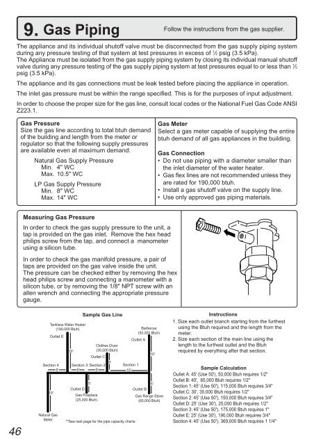
Tankless <strong>Water</strong> Heater<br />
(190,000 Btuh)<br />
Outlet E<br />
Section 4<br />
5'<br />
10'<br />
Sample Gas Line<br />
Outlet A<br />
Clothes Dryer<br />
10'<br />
(35,000 Btuh)<br />
Outlet C<br />
Section 3 Section 2<br />
5'<br />
Section 1<br />
5' 5'<br />
10'<br />
5'<br />
Outlet D<br />
Gas Fireplace<br />
(25,000 Btuh)<br />
**See next page for the pipe capacity charts.<br />
Barbecue<br />
(50,000 Btuh)<br />
10'<br />
5'<br />
Outlet B<br />
Gas Range Stove<br />
(65,000 Btuh)<br />
Instructions<br />
1. Size each outlet branch starting from the furthest<br />
using the Btuh required and the length from the<br />
meter.<br />
2. Size each section of the main line using the<br />
length to the furthest outlet and the Btuh<br />
required by everything after that section.<br />
Sample Calculation<br />
Outlet A: 45' (Use 50'), 50,000 Btuh requires 1/2"<br />
Outlet B: 40', 65,000 Btuh requires 1/2"<br />
Section 1: 45' (Use 50'), 115,000 Btuh requires 3/4"<br />
Outlet C: 30', 35,000 Btuh requires 1/2"<br />
Section 2: 45' (Use 50'), 150,000 Btuh requires 3/4"<br />
Outlet D: 25' (Use 30'), 25,000 Btuh requires 1/2"<br />
Section 3: 45' (Use 50'), 175,000 Btuh requires 1"<br />
Outlet E: 25' (Use 30'), 190,000 Btuh requires 3/4"<br />
Section 4: 45' (Use 50'), 369,000 Btuh requires 1 1/4"


