Integral Tie Rod - Proco Products, Inc.
Integral Tie Rod - Proco Products, Inc.
Integral Tie Rod - Proco Products, Inc.

Create successful ePaper yourself
Turn your PDF publications into a flip-book with our unique Google optimized e-Paper software.
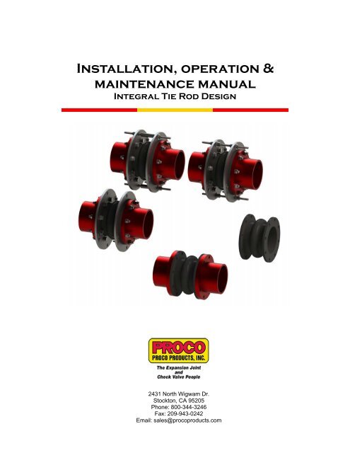
Installation, operation &<br />
maintenance manual<br />
<strong>Integral</strong> <strong>Tie</strong> <strong>Rod</strong> Design<br />
2431 North Wigwam Dr.<br />
Stockton, CA 95205<br />
Phone: 800-344-3246<br />
Fax: 209-943-0242<br />
Email: sales@procoproducts.com
Table of Contents<br />
1.0 Introduction ………………………………………………………… 2<br />
2.0 Storage and Handling …………………………………………….. 2<br />
3.0 Prior to Installation ...……….……………………………………… 3<br />
4.0 Expansion Joint Installation .……………………………………… 6<br />
5.0 System Testing .……………………………………………………. 12<br />
6.0 Operating and Maintenance Procedures .……………………….. 12<br />
7.0 Trouble Shooting .………………………………………………….. 14<br />
APPENDIX A: Torque Data ……………………………………………. 15<br />
APPENDIX B: Installation Record Sheet ……………………………... 17<br />
<strong>Proco</strong> <strong>Products</strong>, <strong>Inc</strong>. Page 1 2012 IOM Spool Type ITR
1.0 Introduction:<br />
<strong>Proco</strong> <strong>Products</strong>, <strong>Inc</strong>. (<strong>Proco</strong>) rubber expansion joints are flexible connectors fabricated of<br />
natural or synthetic elastomers and fabrics, and if necessary metallic reinforcements to provide<br />
stress relief in piping systems due to thermal and mechanical vibrations and/or movements.<br />
This installation, operation and maintenance manual will cover the general practices for the<br />
proper installation, operation and maintenance of the <strong>Proco</strong> “Spool Type” rubber expansion<br />
joints. The <strong>Proco</strong> Spool Type rubber expansion joints covered in this guide include the Series<br />
230, Series 231/BT, Series 251/BT, Series 261R, and Series 271 which all contain integrated<br />
full flat faced flanges as shown in Figure 1.<br />
Full Flat Faced Flan<br />
Figure 1: Spool Type (<strong>Integral</strong> full flat faced flange)<br />
2.0 Storage and Handling:<br />
2.1 Storage:<br />
2.1.1 Inside:<br />
The ideal storage for an<br />
expansion joint is in a<br />
warehouse setting with a<br />
relatively dry and cool location.<br />
Store the flanged expansion<br />
joint face down on a pallet or<br />
wooden platform. Do not lay<br />
other boxes on top of expansion<br />
joint or expansion joint box.<br />
Figure 2: Proper Storage Position<br />
(Left), <strong>Inc</strong>orrect (Right)<br />
2.1.2 Outside:<br />
If the expansion joint is to be stored outside, keep the expansion joint<br />
protected in a waterproof protected crate until ready for installation into the<br />
system. Also keep the expansion joint protected from any external<br />
elements such as direct UV exposure and/or animals from nesting. Do not<br />
lay other boxes on top of expansion joint or expansion joint box.<br />
<strong>Proco</strong> <strong>Products</strong>, <strong>Inc</strong>. Page 2 2012 IOM Spool Type ITR
2.2 Large Joint Handling:<br />
In the case of large size expansion joints,<br />
special care should be taken in loading, hoisting<br />
and lowering, being careful not to hit against<br />
adjacent equipment, forklift tines, crane cables,<br />
etc. Do not lift expansion joints with rope or bars<br />
through the bolt holes. Lift utilizing nylon slings<br />
around the exterior of the expansion joint as<br />
shown in Figure 3. Position the slings to the<br />
side of the arch/arches and not over the arch.<br />
This will help to prevent any damage to the arch<br />
as well as to ensure that the weight is evenly<br />
distributed during installation.<br />
Figure 3: Large Joint Handling<br />
3.0 Prior to Installation:<br />
Note: Do not let expansion joint sit vertically on the edge of its flanges for any period of<br />
time.<br />
3.1 Verify System Parameters:<br />
Check the system design parameters to ensure the supplied expansion joint meets the<br />
requirements of the system and that the system requirements do need exceed the<br />
maximum rated capabilities of the supplied expansion joint. (Pressure, Temperature,<br />
Fluid, expected system movements, etc.)<br />
3.2 Pipe Anchoring/Supports:<br />
PROPERLY ANCHORED<br />
PIPE SYSTEM<br />
PROPERLY SUPPORTED<br />
AND GUIDED PIPE SYSTEM<br />
ANCHORED PUMP<br />
Figure 4: Anchored/Supported System<br />
3.2.1 Anchoring:<br />
Solid anchoring is required wherever the pipeline changes direction, and<br />
expansion joints should be located as close as possible to anchor points. If<br />
anchor points are not used, the pressure thrust may cause excessive<br />
movements and damage the expansion joint.<br />
<strong>Proco</strong> <strong>Products</strong>, <strong>Inc</strong>. Page 3 2012 IOM Spool Type ITR
Note: If the piping system is not properly anchored or anchoring is in<br />
question then the use of control units are required to handle the pressure<br />
thrust loads experienced in the system.<br />
3.2.2 Supports:<br />
3.3 Pipe Alignment:<br />
Check the piping supports where the rubber expansion joint will be<br />
installed. Piping to and from the location of the rubber expansion joint<br />
must be properly supported and guided to ensure that the weight of the<br />
piping is not transferred to the expansion joint.<br />
Inspect the system for alignment as stated in the procedures listed below for Axial,<br />
Lateral, Angular and Torsional alignment. Piping misalignment in the system should<br />
not exceed a maximum of ±1/8” per Fluid Sealing Association (FSA). If the maximum<br />
allowable misalignment is exceeded, the piping should be corrected before installation<br />
of the expansion joint takes place. Note: Expansion joints can be constructed with a<br />
misalignment built in, contact <strong>Proco</strong> <strong>Products</strong>, <strong>Inc</strong>. for additional information at 800-344<br />
-3246.<br />
3.3.1 Axial Alignment:<br />
To measure for axial misalignment,<br />
measure from the inside of one mating<br />
flange to the inside of the other, the<br />
area in which the expansion joint is to<br />
be installed. This measured dimension<br />
should correspond to the ordered<br />
expansion joint’s face-to-face<br />
dimension otherwise an axial<br />
misalignment is indicated.<br />
AXIAL OFFSET<br />
MATING FLANGE<br />
EXPANSION JOINT<br />
Figure 5: Axial Misalignment<br />
3.3.2 Lateral Alignment:<br />
To measure for lateral misalignment,<br />
place a level on the outside edge of the<br />
mating flanges and measure the<br />
distance across. Repeat the<br />
measurement at least 3 times to obtain<br />
a total of 4 measurements evenly<br />
distributed around the circumference of<br />
the mating flanges (6-8 total<br />
measurements for large ID expansion<br />
joints). Any variation in the measured<br />
dimensions and an inconsistency in the<br />
level, indicates a lateral misalignment.<br />
LATERAL OFFSET<br />
MATING FLANGE<br />
EXPANSION JOINT<br />
Figure 6: Lateral Misalignment<br />
<strong>Proco</strong> <strong>Products</strong>, <strong>Inc</strong>. Page 4 2012 IOM Spool Type ITR
3.3.3 Angular Alignment:<br />
To measure for angular misalignment<br />
between mating flanges, measure from<br />
the edge of one flange to the same<br />
corresponding spot on the opposing<br />
flange. Record this value and then<br />
repeat the same measurement on the<br />
opposite side of the flanges (180º from<br />
the initial measurement). Repeat these<br />
measurements to obtain a total of at<br />
least 4 paired measurements evenly<br />
distributed around the circumference of<br />
the flanges. Compare the measured<br />
dimensions and any variation in the<br />
measured dimensions indicates that the<br />
mating flanges are not parallel and are<br />
angularly misaligned.<br />
ANFULAR OFFSET<br />
MATING FLANGE<br />
EXPANSION JOINT<br />
Figure 7: Angular Misalignment<br />
TORSIONAL OFFSET<br />
3.3.4 Torsional Alignment:<br />
Check the flange bolt pattern on each<br />
mating flange and ensure the bolt holes<br />
on each flange line up to each other.<br />
Any variation as shown in Figure 8 will<br />
indicate a torsional misalignment.<br />
EXPANSION JOINT<br />
MATING FLANGE<br />
Figure 8: Torsional Misalignment<br />
3.4 Concurrent Movement Calculation:<br />
Concurrent movements are developed when two or more movements in a pipe system<br />
occur at the same time. To perform the calculation for concurrent movements when a<br />
pipe system has more than one movement, use the following formula:<br />
Actual Axial Actual Lateral Actual Angular Actual Torsional<br />
+<br />
+<br />
+<br />
Rated Axial Rated Lateral Rated Angular Rated Torsional<br />
≤ 1<br />
Calculation must be < 1 for expansion joint to operate within concurrent movement<br />
capabilities.<br />
Note: Lateral offsets can be found in two planes.<br />
<strong>Proco</strong> <strong>Products</strong>, <strong>Inc</strong>. Page 5 2012 IOM Spool Type ITR
3.5 Unpack/Inspect Expansion Joint:<br />
Remove the expansion joint from the packaging and if applicable verify that the tag<br />
information corresponds with the point of installation into the system. Check the outer<br />
cover and the internal tube or bonded liner depending on the style of expansion joint<br />
ordered for any damage before placing in service. The cover and tube/liner are<br />
designed to keep harmful materials from penetrating the carcass of the joint.<br />
Penetration of the cover or tube/liner by harmful materials can cause premature failure<br />
of the expansion joint. If the outer cover and/or inner tube/liner is damaged during<br />
unpacking or installation contact <strong>Proco</strong> <strong>Products</strong>, <strong>Inc</strong>. by phone: 209-943-6088, by<br />
facsimile: 209-943-0242 or by e-mail: sales@procoproducts.com, to determine a<br />
course of action before the expansion joint is placed into service.<br />
4.0 Expansion Joint Installation:<br />
4.1 Installation Precautions:<br />
4.1.1 Adjacent Equipment:<br />
Never install expansion joints that utilize integral tie rod plates next to<br />
wafer-type check or butterfly valves. Serious damage can result to a<br />
rubber expansion joint of this type unless installed against full-faced<br />
flanges.<br />
CONTROL ROD PLACEMENT<br />
INTERFERENCE<br />
NOT A FULL FLAT<br />
FACED MATING SURFACE<br />
VALVE MAY INTERFERE AND DAMAGE<br />
RUBBER EXPANSION JOINT<br />
Figure 9: Adjacent Equipment Precaution<br />
4.1.2 Insulating Over Expansion joint:<br />
It is suggested not to insulate over a non-metallic expansion joint. If<br />
insulation is required, it should be made removable to permit easy access<br />
to the flanges. Removable insulation will facilitate periodic inspection of<br />
the expansion joint material and allow for tightening of expansion joint<br />
bolts. (It should be noted that insulation could cause restriction of<br />
expansion joint movement and/or excessive heating of the expansion joint<br />
material to exceed the maximum rated capability of the expansion joint.)<br />
<strong>Proco</strong> <strong>Products</strong>, <strong>Inc</strong>. Page 6 2012 IOM Spool Type ITR
4.1.3 Heat Tracing Over Expansion Joint:<br />
Do not use heat tracing over expansion joints.<br />
HEAT TRACING<br />
HEAT TRACING<br />
STRAP<br />
Figure 10: Do Not Heat Trace Over Expansion Joint<br />
4.1.4 Welding Near Expansion Joints:<br />
4.2 Installation Procedures:<br />
Take precautions when welding next to or near an expansion joint. Weld<br />
splatter can damage the rubber material, thus decreasing overall<br />
performance during operation. If welding near a rubber expansion joint, it<br />
is suggested that a welding blanket be used to protect against damage.<br />
INTEGRAL TIE ROD (ITR) PLATE<br />
WASHER<br />
COMPRESSION SLEEVE<br />
(OPTIONAL CONFIGURATION)<br />
CONTROL ROD<br />
ROD NUT<br />
MATING FLANGE<br />
FLANGE BOLTING HARDWARE<br />
MEND PLATE<br />
SPOOL TYPE EXPANSION JOINT<br />
MEND PLATE HARWARE<br />
Figure 11: Standard Components of an Expansion Joint Assembly<br />
<strong>Proco</strong> <strong>Products</strong>, <strong>Inc</strong>. Page 7 2012 IOM Spool Type ITR
Step 1: Inspect the mating flanges to ensure that they are clean and free of all<br />
foreign matter before installing the rubber expansion joint. A flat face mating flange<br />
is preferred. If raised face flanges are to be used, the flange lip is to be no more<br />
than 1/16” tall. If the mating flange is plastic or FRP it is recommended to use a<br />
stiffener ring to reinforce the mating flange.<br />
Step 2: Place and align the expansion joint into the system. Take care when<br />
installing the expansion joint into the system to prevent any damage to the<br />
expansion joint, refer to section 2.2 for large joint handling if applicable. To<br />
facilitate installation of expansion joints with acceptable misalignment, it is<br />
acceptable to use tapered pins to align the expansion joint to the bolt holes on the<br />
mating flange to ease installation of flange bolting as shown in Figure 13.<br />
Note: It is acceptable, but not necessary to lubricate the expansion joint flanges<br />
with a thin film of graphite dispersed in Glycerin or water to ease disassembly at a<br />
later time. (Petroleum lubricants should not be used on rubber expansion joints.)<br />
Figure 12: Place Expansion joint Into System<br />
MATING FLANGE<br />
RUBBER FLANGE<br />
TAPERED PINS<br />
ITR PLATE<br />
Figure 13: Installing Expansion Joint with Minor Misalignment<br />
Step 3: Position the <strong>Integral</strong> <strong>Tie</strong> <strong>Rod</strong> (ITR) plates on the expansion joint assembly<br />
as shown in Figure 14.<br />
<strong>Proco</strong> <strong>Products</strong>, <strong>Inc</strong>. Page 8 2012 IOM Spool Type ITR
Figure 14: Position ITR Plates<br />
Step 4: Secure the ITR plates in place with the flange bolting and the provided<br />
mend plates. Position the flange bolt head and washer against the ITR plate as<br />
shown in Figure 15. Washers must be used at least at the split in the ITR plate or<br />
else flange leakage may occur.<br />
Figure 15: Secure Retaining Rings to Assembly<br />
Step 5: Once the expansion joint and ITR plates are in place tighten all bolts to a<br />
“snug” tight fit before they are torqued. Torqueing should then be accomplished in<br />
steps gradually and as evenly as possible around the flange. The bolts should be<br />
tightened in an alternating sequence similar to the star pattern shown in Figure 18<br />
to within the proper torque range specified for the style of expansion joint to be<br />
installed. The bolts are not considered tight and “locked-on” until the edge of the<br />
expansion joint flange bulges out or extrudes slightly. Refer to Appendix A for the<br />
proper ranges of torque values for the spool type expansion joints as well as<br />
further examples of the proper patterns used for torqueing the flange bolting. The<br />
use of stud bolting is acceptable as long as no more than 2-4 threads extend past<br />
the nut facing the expansion joint. Excessive amounts of threading extending<br />
toward the expansion joint can case damage to the expansion joint as it expands<br />
resulting in a reduced service life and an increased possibility of failure.<br />
Note: Never tighten bolts on a rubber expansion joint to the point where there is<br />
contact between the retaining ring and mating flange. This type of tightening will<br />
crush the rubber expansion joint and cause premature failure.<br />
<strong>Proco</strong> <strong>Products</strong>, <strong>Inc</strong>. Page 9 2012 IOM Spool Type ITR
Figure 17: Add Flange Bolting Nuts to Assembly<br />
7<br />
1<br />
3<br />
5<br />
6<br />
4<br />
2<br />
8<br />
Figure 18: Sample Flange Bolting Torque Pattern<br />
Step 6: Insert the control rod through the ITR plate holes while adding the<br />
additional hardware as shown in Figure 19 for a typical installation with internal<br />
hardware or as shown in Figure 20 which utilizes compression sleeves instead of<br />
internal hardware. Replace flat washers with spherical washers whenever<br />
application requires.<br />
Figure 19: Control <strong>Rod</strong> with Internal Hardware Installation<br />
<strong>Proco</strong> <strong>Products</strong>, <strong>Inc</strong>. Page 10 2012 IOM Spool Type ITR
Figure 20: Control <strong>Rod</strong> with Compression Sleeve Installation<br />
Step 7: When setting control rod gaps and/or the compression sleeve length for<br />
anchored systems, the outer nuts are to be positioned to meet maximum extension<br />
requirements and the inner nuts or compression sleeve should be positioned or cut<br />
to a minimum length that will allow for the maximum compression requirements.<br />
Compression<br />
Sleeve Length =<br />
Face-To-Face Dimension<br />
of Expansion Joint<br />
-<br />
2 x Rubber Flange<br />
Thickness -<br />
2 x ITR Plate<br />
Thickness<br />
-<br />
Total Compression<br />
Required<br />
The control rod gaps and/or compression sleeve lengths are to be determined by<br />
the project or site engineer. The combined gaps on the control rods are not to<br />
exceed the maximum rated movement capabilities of the supplied expansion joint.<br />
For unanchored systems there should be no control rod gaps in the control rod<br />
hardware, all hardware on the control rods should be snug to the ITR plates as<br />
shown in Figure 23.<br />
Note: Please contact <strong>Proco</strong> <strong>Products</strong>, <strong>Inc</strong>. by phone: 209-943-6088, facsimile: 209<br />
-943-0242, or e-mail: sales@procoproducts.com, if there are any questions as to<br />
the rated compression or extension movements.<br />
HALF OF ALLOWABLE EXTENSION<br />
HALF OF ALLOWABLE<br />
COMPRESSION<br />
Figure 21: Setting of Control <strong>Rod</strong> Gap with Internal Hardware<br />
HALF OF ALLOWABLE EXTENSION<br />
HALF OF ALLOWABLE<br />
COMPRESSION<br />
Figure 22: Setting of Control <strong>Rod</strong> Gap with Compression Sleeves<br />
<strong>Proco</strong> <strong>Products</strong>, <strong>Inc</strong>. Page 11 2012 IOM Spool Type ITR
HARDWARE SNUG TO ITR PLATES FOR UNANCHORED SYSTEM<br />
HARDWARE SNUG TO ITR PLATES FOR UNANCHORED SYSTEM<br />
5.0 System Testing:<br />
Figure 23: Control <strong>Rod</strong> Gap for Unanchored System<br />
5.1 System Pressure Test:<br />
5.1.1 Follow pressure test instructions set by site engineer. Lock down control<br />
rod hardware before pressure test as shown in Figure 23. Pressure test<br />
should not exceed 1.5 times operating pressure for 10 minutes. Refer to<br />
specified drawing for pressure rating and details.<br />
5.2 After Pressure Test<br />
5.2.1 After the pressure test is conducted de-pressurize the system and check<br />
the flange bolting. Tighten bolts as necessary as bolts may loosen as<br />
rubber flange takes a set.<br />
6.0 Operation and Maintenance Procedures:<br />
6.1 Inspection of Rubber Expansion Joint at Shut-Down:<br />
EXPANSION JOINT COVER<br />
REINFORCING FABRIC<br />
COVER<br />
METAL REINFORCEMENT<br />
EXPANSION JOINT<br />
RUBBER TUBE<br />
OR<br />
BONDED LINER<br />
RUBBER TUBE<br />
OR<br />
BONDED LINER<br />
Figure 24: Typical Expansion Joint Make-Up<br />
6.1.1 Cover Inspection:<br />
Rubber expansion joints should be visually inspected at shutdowns. Look<br />
for any signs of cracks in the outer cover that shows exposed fabric<br />
reinforcement. If fabric reinforcement is exposed, the expansion joint must<br />
be replaced.<br />
<strong>Proco</strong> <strong>Products</strong>, <strong>Inc</strong>. Page 12 2012 IOM Spool Type ITR
6.1.2 Tube/Liner Inspection:<br />
If inspection of the internal rubber tube or bonded liner of the expansion<br />
joint is possible look for signs of exposed fabric, excessive wear or<br />
cracking. If the inner tube or bonded liner show any of these signs, the<br />
expansion joint must be replaced.<br />
6.2 Expansion Joint Bolt Check:<br />
Check expansion joint at least one week after start-up to ensure that bolts are tight on<br />
expansion joint and the ITR assembly. As any rubber-like material takes a “set” after a<br />
period of compression, bolts may loosen; thus resulting in a possible broken seal<br />
between the expansion joint and the mating flange. Periodically check bolting to<br />
ensure bolts are tight. Tighten as necessary.<br />
Note: Ensure system is de-pressurized before tightening flange bolting.<br />
6.3 Service Conditions:<br />
Make sure the expansion joint operates at the temperature, pressure, vacuum, and<br />
movements matching the original requirements. Contact <strong>Proco</strong>’s Customer Service<br />
Department by phone: 209-943-6088, facsimile: 209-943-2042, or e-mail:<br />
sales@procoproducts.com, if the system requirements exceed those specified.<br />
6.4 Breaking the Rubber Expansion Joint Seal:<br />
In the event a rubber expansion joint is to be removed from the system and put back in<br />
service at a later date, the seal between the mating flange and expansion joint will<br />
need to be broken. Drive small wooden wedges along the perimeter between the<br />
rubber flange and pipe flange. With proper care the connection can be broken without<br />
damage to the rubber expansion joint and the adjacent pipe flanges.<br />
Figure 25: Breaking of Expansion Joint Seal<br />
<strong>Proco</strong> <strong>Products</strong>, <strong>Inc</strong>. Page 13 2012 IOM Spool Type ITR
6.5 Spares:<br />
7.0 Trouble Shooting<br />
A rubber expansion joint spare should be put in stock in the event a mechanical failure<br />
occurs. Stock one (1) spare for each size purchased. Although these expansion joints<br />
are engineered to give long, dependable service, the cost of equipment downtime, in<br />
the event of a mechanical failure, can far outweigh the cost of a spare. Spares will be<br />
packaged in waterproof crates and prepared for storage.<br />
7.1 Leaking at the Flange:<br />
7.1.1 The flange bolts may need retightening. On the rubber expansion joints<br />
the flange bolting should be tight enough to make the edge of the rubber<br />
flange bulge slightly between the metal flange and the retaining rings.<br />
Ensure system is depressurized before tightening the flange bolting.<br />
7.1.2 The surface of the mating flange may be in poor condition. Make sure<br />
there are no excessive grooves, scratches or distorted areas.<br />
7.1.3 The joint may have been over-extended to such an extent that it has<br />
caused the rubber flange to pull away from the mating flange. If so, verify<br />
that the control unit was properly installed and an appropriate control rod<br />
gap was set.<br />
7.2 Cracking at Base of Arch or Flange:<br />
Make sure the installed face-to-face dimension is correct so that the joint is not overextended<br />
or over-compressed. Check to see if the pipes are properly aligned so there<br />
is no excessive misalignment. Pipes should not be more than1/8” out of alignment.<br />
Check to see if system is properly anchored or if control rods are used. External<br />
cracking of cover does not mean failure. This is often caused by exposure to strong<br />
sunlight in an extended condition. If cracking extends to the fabric reinforcing member,<br />
the expansion joint must be replaced.<br />
7.3 Liquid Weeping through Bolt Holes:<br />
Look for a break in the tube portion of the joint. If there is a crack or a break, the joint<br />
must be replaced as soon as possible.<br />
7.4 Excessive Ballooning of Arch:<br />
Ballooning is usually an indication of deterioration of the joint’s strengthening members<br />
or excessive pressure in the system. Service conditions should be double-checked<br />
and a new joint must be installed.<br />
<strong>Proco</strong> <strong>Products</strong>, <strong>Inc</strong>. Page 14 2012 IOM Spool Type ITR
APPENDIX A: Torque Data<br />
Table 1: Spool Type Torque Values<br />
Size Approx. Torque Values<br />
1" thru 2" 20 ‐ 40 ./lbs.<br />
2.5" thru 5" 25 ‐ 60 ./lbs.<br />
6" thru 12" 35 ‐ 140 ./lbs.<br />
14" thru 18" 50 ‐ 180 ./lbs.<br />
20" thru 24" 60 ‐ 200 ./lbs.<br />
26" thru 40" 70 ‐ 300 ./lbs.<br />
42" thru 50" 80 ‐ 300 ./lbs.<br />
52" thru 60" 100 ‐ 400 ./lbs.<br />
66" thru 72" 200 ‐ 500 ./lbs.<br />
78" thru 90" 300 ‐ 600 ./lbs.<br />
96" thru 108" 400 ‐ 700 ./lbs.<br />
120" 500 ‐ 800 ./lbs.<br />
<strong>Proco</strong> <strong>Products</strong>, <strong>Inc</strong>. Page 15 2012 IOM Spool Type ITR
APPENDIX A: Torque Data<br />
7 1<br />
3 1<br />
3 5<br />
2<br />
15<br />
11<br />
7<br />
3<br />
6<br />
4 10<br />
4<br />
4<br />
2 8 6<br />
8<br />
2 12<br />
19 1<br />
5<br />
23<br />
19<br />
9<br />
15<br />
20"<br />
3<br />
13<br />
11<br />
17<br />
7<br />
11 1<br />
7<br />
5<br />
9<br />
4" 8" 12"<br />
18 4<br />
14<br />
8<br />
10<br />
12<br />
6<br />
16<br />
2 20<br />
27 1<br />
23<br />
19<br />
15<br />
11<br />
3<br />
22<br />
18<br />
14<br />
5<br />
10<br />
6<br />
9<br />
2<br />
13<br />
17<br />
3<br />
14<br />
15 1<br />
11<br />
7<br />
10<br />
6<br />
1<br />
5<br />
26"<br />
16"<br />
2 16<br />
9<br />
13<br />
17<br />
8<br />
12<br />
16<br />
20<br />
24<br />
21<br />
4<br />
5<br />
12<br />
9<br />
13<br />
4<br />
8<br />
7<br />
21<br />
3<br />
26<br />
30"<br />
25<br />
4<br />
22<br />
8<br />
18<br />
12<br />
14<br />
10<br />
6<br />
2 28<br />
24<br />
16<br />
20<br />
Figure 26: Sample Torque Patterns<br />
<strong>Proco</strong> <strong>Products</strong>, <strong>Inc</strong>. Page 16 2012 IOM Spool Type ITR
APPENDIX B: Installation Record Sheet<br />
Attached are the Installation record sheets, below is an overview of the details of the<br />
attached installation record sheets.<br />
Expansion Joint Information:<br />
<strong>Proco</strong> Style:<br />
Size (Nom. I.D. x F/F Length):<br />
Purchase Order No.:<br />
Date of Order/Shipment:<br />
Drawing Number:<br />
Tag No.:<br />
<strong>Proco</strong> Style of Expansion Joint Supplied<br />
Nominal I.D. x Face-To-Face Length<br />
System Installation Information<br />
Installation Date: Date of Installation<br />
1. Medium Gas/Liquid/Steam: Type of Fluid and the State of the Fluid in the System<br />
2. Operating Pressure: Operating Pressure of the System<br />
3. Surge Pressure/Duration: Surge Pressure Experienced in the System and Duration<br />
4. Operating Temperature: Operating Temperature of the System<br />
5. Surge Temperature/Duration: Temperature at Surge Pressure and Duration<br />
6. Confirm Expected Movements in the System:<br />
a. Axial Compression: Expected Axial Compression for Expansion Joint to Compensate<br />
b. Axial Extension: Expected Axial Extension for Expansion Joint to Compensate<br />
c. Lateral Deflection: Expected Lateral Deflection for Expansion Joint to Compensate<br />
d. Angular Deflection: Expected Angular Deflection for Expansion Joint to Compensate<br />
e. Torsional Rotation: Expected Torsional Rotation for Expansion Joint to Compensate<br />
7. Verify System is Properly Anchored/Guided: Verify Anchors and Guides in the System<br />
Notes:<br />
8. Distance to Nearest Anchor Point (each end): Measure the Distance to the Nearest Anchor Points<br />
9. Mating Flange Rating/Type (RF/FF): Rating and Type of Mating Flanges<br />
10. Verify Mating Flanges are Parallel: Verify that the Mating Flanges are Parallel to each other<br />
11. Verify Centerline Alignment: Verify that the Point of Installation is Properly Aligned to the Centerline<br />
12. Verify Axial Alignment: Verify Axial Alignment for the Point of Installation<br />
13. Verify Lateral Alignment: Verify Lateral Alignment for the Point of Installation<br />
14. Verify Angular Alignment: Verify Angular Alignment for the Point of Installation<br />
15. Verify Torsional (Rotational) Alignment: Verify Torsional Alignment for Point of Installation<br />
16. Installation Orientation (Horiz/Vert): Record Installation Orientation of Expansion Joint<br />
17. Installed Face-To-Face Length (measured in 4 positions):<br />
a. 3 O’clock Flange Position: Measure Face-To-Face Dimension at Specified Flange Position<br />
b. 6 O’clock Flange Position: Measure Face-To-Face Dimension at Specified Flange Position<br />
c. 9 O’clock Flange Position: Measure Face-To-Face Dimension at Specified Flange Position<br />
d. 12 O’clock Flange Position: Measure Face-To-Face Dimension at Specified Flange Position<br />
18. Average Bolt Torque: Record Average Bolt Torque used to Secure Expansion Joint to Mating Flanges<br />
19. Control <strong>Rod</strong>s:<br />
a. Number of Control <strong>Rod</strong>s: Record Number of Control <strong>Rod</strong>s Used<br />
b. Control <strong>Rod</strong> Gap/Compression Sleeve Length: Record the Control <strong>Rod</strong> Gap/Sleeve Length<br />
Notes:<br />
<strong>Proco</strong> <strong>Products</strong>, <strong>Inc</strong>. Page 17 2012 IOM Spool Type ITR
Installation Record Sheet<br />
Expansion Joint Information:<br />
<strong>Proco</strong> Style:<br />
Size (Nom. I.D. x F/F Length):<br />
Purchase Order No.:<br />
Date of Order/Shipment:<br />
Drawing Number:<br />
Tag No.:<br />
System Installation Information<br />
Installation Date:<br />
1. Medium Gas/Liquid/Steam:<br />
2. Operating Pressure:<br />
3. Surge Pressure/Duration:<br />
4. Operating Temperature:<br />
5. Surge Temperature/Duration:<br />
6. Confirm Expected Movements in the System:<br />
a. Axial Compression:<br />
b. Axial Extension:<br />
c. Lateral Deflection:<br />
d. Angular Deflection:<br />
e. Torsional Rotation:<br />
7. Verify System is Properly Anchored/Guided:<br />
Notes:<br />
8. Distance to Nearest Anchor Point (each end):<br />
9. Mating Flange Rating/Type (RF/FF):<br />
10. Verify Mating Flanges are Parallel:<br />
11. Verify Centerline Alignment:<br />
12. Verify Axial Alignment:<br />
13. Verify Lateral Alignment:<br />
14. Verify Angular Alignment:<br />
15. Verify Torsional (Rotational) Alignment:<br />
16. Installation Orientation (Horiz/Vert):<br />
17. Installed Face-To-Face Length (measured in 4 positions):<br />
a. 3 O’clock Flange Position:<br />
b. 6 O’clock Flange Position:<br />
c. 9 O’clock Flange Position:<br />
d. 12 O’clock Flange Position:<br />
18. Average Bolt Torque:<br />
19. Control <strong>Rod</strong>s:<br />
Number of Control <strong>Rod</strong>s:<br />
Control <strong>Rod</strong> Gap/Compression Sleeve Length:<br />
Notes:<br />
<strong>Proco</strong> <strong>Products</strong>, <strong>Inc</strong>.<br />
2431 North Wigwam Dr.<br />
Stockton, CA 95205<br />
Phone: 800-344-3246<br />
Fax: 209-943-0242<br />
Email: sales@procoproducts.com