Style 240/242 - Proco Products, Inc.
Style 240/242 - Proco Products, Inc.
Style 240/242 - Proco Products, Inc.

Create successful ePaper yourself
Turn your PDF publications into a flip-book with our unique Google optimized e-Paper software.
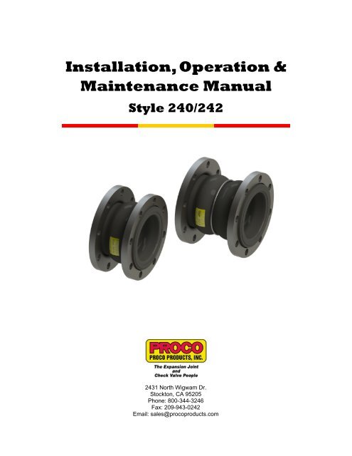
Installation, Operation &<br />
Maintenance Manual<br />
<strong>Style</strong> <strong>240</strong>/<strong>242</strong><br />
2431 North Wigwam Dr.<br />
Stockton, CA 95205<br />
Phone: 800-344-3246<br />
Fax: 209-943-0<strong>242</strong><br />
Email: sales@procoproducts.com
Table of Contents<br />
1.0 Introduction: 2<br />
2.0 Storage and Handling: 2<br />
2.1 Storage: 2<br />
2.2 Large Joint Handling: 3<br />
3.0 Prior to Installation: 3<br />
3.1 Verify System Parameters: 3<br />
3.2 Pipe Anchoring/Supports: 3<br />
3.3 Pipe Alignment: 4<br />
3.4 Concurrent Movement Calculation: 5<br />
3.5 Unpack/Inspect Expansion Joint: 5<br />
4.0 Expansion Joint Installation: 6<br />
4.1 Installation Precautions: 6<br />
4.2 Control Unit Installation Configurations: 7<br />
4.3 Installation Procedures: 9<br />
5.0 System Testing: 14<br />
6.0 Operation and Maintenance Procedures: 14<br />
7.0 Trouble Shooting: 15<br />
Appendix A: Torque Data: 16<br />
Appendix B: Installation Record Sheet: 18<br />
<strong>Proco</strong> <strong>Products</strong>, <strong>Inc</strong>. Page 1 2013 IOM <strong>240</strong>/<strong>242</strong>
1.0 Introduction:<br />
<strong>Proco</strong> <strong>Products</strong>, <strong>Inc</strong>. (<strong>Proco</strong>) rubber expansion joints are flexible connectors fabricated of natural or synthetic<br />
elastomers and fabrics and if necessary metallic reinforcements, to provide stress relief in piping systems due to<br />
thermal expansion/contraction, mechanical vibration and/or system movements. This installation, operation and<br />
maintenance manual will cover the general practices for the proper installation, operation and maintenance of the<br />
<strong>Proco</strong> molded spherical type rubber expansion joints. The <strong>Proco</strong> style of rubber expansion joints covered in this<br />
guide include the style <strong>240</strong> and style <strong>242</strong>, molded rubber expansion joints incorporating floating flanges.<br />
Figure 1: <strong>Style</strong> <strong>240</strong> & <strong>242</strong><br />
Note: The style <strong>242</strong> comes with a reinforcing ring in-between the 2 arches and depending on the size the reinforcing<br />
ring is either embedded in the carcass or exposed.<br />
2.0 Storage and Handling<br />
2.1 Storage<br />
2.1.1 Inside:<br />
The ideal storage location for an expansion joint is in a warehouse setting with a relatively dry<br />
and cool location. Store the expansion joint face down on a pallet or wooden platform. Do not<br />
lay other boxes on top of the expansion joint or expansion joint box.<br />
2.1.2 Outside<br />
If the expansion joint is to be stored outside, keep the expansion joint protected in a waterproof<br />
protected crate until ready for installation. Also keep the expansion joint protected from any<br />
external elements such as direct UV exposure and/or animals. Do not lay other boxes on top of<br />
the expansion joint or expansion joint box.<br />
<strong>Proco</strong> <strong>Products</strong>, <strong>Inc</strong>. Page 2 2013 IOM <strong>240</strong>/<strong>242</strong>
2.2 Large Expansion Joint Handling:<br />
In the case of large size expansion joints,<br />
special care should be taken in loading, hoisting<br />
and lowering, being careful not to hit against<br />
adjacent equipment, forklift tines, crane cables,<br />
etc. Lift utilizing nylon slings around the exterior<br />
of the expansion joint as shown in Figure 2.<br />
Position the slings to each side of the arch; this<br />
will help prevent any damage to the arch as well<br />
as to ensure that the weight is evenly distributed<br />
during installation.<br />
Figure 2: Large Joint Handling<br />
3.0 Prior to Installation:<br />
3.1 Verify System Parameters<br />
Check the system design parameters for the point of installation to ensure that the supplied expansion<br />
joint meets the system requirements and that the system requirements do not exceed the rated<br />
capabilities of the supplied expansion joint. (Pressure, Temperature, Material Compatibility, System<br />
Movements)<br />
3.2 Pipe Anchoring/Supports<br />
PROPERLY ANCHORED<br />
PIPE SYSTEM<br />
PROPERLY SUPPORTED<br />
AND GUIDED PIPE SYSTEM<br />
ANCHORED PUMP<br />
3.2.1 Anchoring:<br />
Figure 3: Properly Anchored and Supported/Guided System<br />
Solid anchoring is required wherever the pipeline changes direction and expansion joints should<br />
be located as close as possible to anchor points. If proper anchor points are not used, the<br />
pressure thrust may cause excessive movements in the expansion joint and cause damage.<br />
<strong>Proco</strong> <strong>Products</strong>, <strong>Inc</strong>. Page 3 2013 IOM <strong>240</strong>/<strong>242</strong>
3.2.2 Supports:<br />
3.3 Pipe Alignment<br />
Check the piping supports where the rubber expansion joint will be installed. Piping to and from<br />
the location of installation for the expansion joint must be properly supported and guided to<br />
ensure that the weight of the piping is not transferred to the expansion joint.<br />
Inspect the system for proper alignment as stated in the procedures listed below for axial, lateral, angular<br />
and torsional alignment. Piping misalignment in the system should not exceed a maximum of ±1/8” per the<br />
Fluid Sealing Association (FSA). If the maximum allowable misalignment is exceeded, the piping should<br />
be corrected before installation of the expansion joint. The piping must be prepared to receive the rubber<br />
expansion joint, never the contrary, as this would result in compressing, extending, laterally deflecting or<br />
angularly bending the expansion joint until it fits into the available clearance for installation. This will result<br />
in additional movements for the expansion joint, thereby decreasing its movement capabilities during<br />
operation and lead to a possible failure.<br />
3.3.1 Axial Misalignment<br />
AXIAL OFFSET<br />
To measure for axial misalignment, measure the<br />
perpendicular distance from the inside of one<br />
mating flange to the inside of the other, the area in<br />
which the expansion joint is to be installed. This<br />
measured dimension should correspond to the<br />
ordered expansion joint’s face-to-face or overall<br />
length dimension otherwise an axial misalignment<br />
is indicated.<br />
3.3.2 Lateral Misalignment<br />
To measure for lateral misalignment, place a<br />
level on the outside edge of the mating flanges<br />
and measure the distance across. Repeat the<br />
measurement at least 3 times to obtain a total of<br />
4 measurements evenly distributed around the<br />
circumference of the mating flanges (6-8 total<br />
measurements for large ID expansion joints). Any<br />
variation in the measured dimensions and an<br />
inconsistency in the level, indicates a lateral<br />
misalignment.<br />
3.3.3 Angular Misalignment<br />
To measure for angular misalignment between<br />
mating flanges, the distance from one mating flange<br />
to the other will need to me measured. Measure the<br />
perpendicular distance from the inside of one<br />
mating flange to the inside surface of the other<br />
mating flange. Take several of these measurements<br />
in various positions around the mating flanges. Any<br />
variation in the measured dimensions indicates that<br />
the mating flanges are not parallel and are angularly<br />
misaligned.<br />
Figure 4: Axial Misalignment<br />
LATERAL OFFSET<br />
Figure 5: Lateral Misalignment<br />
ANGULAR OFFSET<br />
Figure 6: Angular Misalignment<br />
<strong>Proco</strong> <strong>Products</strong>, <strong>Inc</strong>. Page 4 2013 IOM <strong>240</strong>/<strong>242</strong>
3.3.4 Torsional Misalignment<br />
For installations utilizing control units with the <strong>Style</strong><br />
<strong>240</strong> or <strong>242</strong> molded spherical type expansion joints,<br />
check the flange bolt pattern on each mating flange<br />
and ensure the bolt holes on each flange line up to<br />
each other. Any variation as shown in Figure 7 will<br />
indicate a torsional misalignment and may interfere<br />
with the proper installation of the control units.<br />
3.4 Concurrent Movement Calculation<br />
TORSIONAL OFFSET<br />
Figure 7: Torsional<br />
Misalignment<br />
Concurrent movements are developed when two or more movements in a pipe system occur at the same<br />
time. To perform the calculation for concurrent movements when a pipe system has more than one<br />
movement, use the following equation:<br />
Equation 1: Concurrent Movement Calculation:<br />
Actual Axial Actual Lateral Actual Angular<br />
+<br />
+<br />
Rated Axial Rated Lateral Rated Angular<br />
< 1<br />
The calculation must be
4.0 Expansion Joint Installation:<br />
4.1 Installation Precautions:<br />
4.1.1 Adjacent Equipment:<br />
Never install rubber expansion joints next to wafer-type check or butterfly valves. Serious<br />
damage can result to a rubber expansion joint of this type unless installed against full-faced<br />
flanges.<br />
VALVE MAY INTERFERE WITH PROPER<br />
PLACEMENT OF CONTROL UNIT HARDWARE<br />
NOT A PROPER MATING SURFACE FOR<br />
MOLDED SPHERICAL TYPE EXPANSION JOINTS<br />
VALVE MAY INTERFERE AND DAMAGE<br />
RUBBER EXPANSION JOINT<br />
4.1.2 Insulating Over Expansion Joint:<br />
Figure 9: Adjacent Equipment Precaution<br />
It is suggested not to insulate over a non-metallic expansion joint. If insulation is required, it<br />
should be made removable to permit easy access to flanges. Removable insulation will facilitate<br />
periodic inspection of the expansion joint material and allow for tightening of expansion joint<br />
bolts.<br />
Note: Insulation could cause restriction of expansion joint movement and/or excessive heating<br />
of the expansion joint material to exceed the maximum rated capability of the expansion joint.<br />
4.1.3 Heat Tracing Over Expansion Joint:<br />
Do not use head tracing over expansion joints.<br />
4.1.4 Welding Near Expansion Joints:<br />
Take precautions when welding next to or near a rubber expansion joint. Weld splatted can<br />
damage the rubber material, decreasing overall performance during operation. If welding near a<br />
rubber expansion joint it is suggested to use a welding blanked to protect against any damage.<br />
4.1.5 Painting over Expansion Joints:<br />
Do not paint over the rubber element of the expansion joint.<br />
4.1.6 Multiple expansion joints in line:<br />
Never install more than one standard expansion joint assembly between two main anchors<br />
unless otherwise specified.<br />
<strong>Proco</strong> <strong>Products</strong>, <strong>Inc</strong>. Page 6 2013 IOM <strong>240</strong>/<strong>242</strong>
4.2 Control Unit Installation Configurations:<br />
CONTROL ROD WITH<br />
STAKED NUT<br />
CONTROL ROD<br />
WASHER<br />
HEX NUT<br />
COMPRESSION SLEEVE<br />
CONTROL UNIT PLATE<br />
MOLDED SPHERE TYPE EXPANSION JOINT<br />
WITH FLOATING FLANGES<br />
MOLDED SPHERE TYPE EXPANSION JOINT<br />
WITH INTEGRAL TIE ROD DESIGNED<br />
FLOATING FLANGES<br />
Figure 10: General Installation Components<br />
Note: Integral Tie Rod designed floating flanges come in multiple styles and the one depicted is of a<br />
general style.<br />
4.2.1 No Control Units Configuration:<br />
The installation configuration shown in Figure 11<br />
does not utilize control units. This configuration<br />
is only applicable for properly anchored and<br />
supported pipe systems.<br />
Figure 11: No Control Unit Configuration<br />
4.2.2 Figure 1: Limit Rod Configuration:<br />
The Figure 1: Limit Rod configuration shown in<br />
Figure 12, otherwise known as Figure 1 is<br />
designed to control only the extension<br />
capabilities of the expansion joint as well as<br />
restrain the pressure thrust loads for nonproperly<br />
anchored systems.<br />
Figure 12: Figure 1 Limit Rod Configuration<br />
<strong>Proco</strong> <strong>Products</strong>, <strong>Inc</strong>. Page 7 2013 IOM <strong>240</strong>/<strong>242</strong>
4.2.3 Figure 2: Control Rod Configuration:<br />
The Figure 2: Control Rod configuration<br />
shown in Figure 13, otherwise known as<br />
Figure 2 is designed to control both the<br />
extension and compression capabilities<br />
of the expansion joint as well as restrain<br />
the pressure thrust loads experienced<br />
across the expansion joint.<br />
Figure 13: Figure 2 Control Rod Configuration<br />
4.2.4 Figure 3: Compression Sleeve Configuration:<br />
The Figure 3: Compression Sleeve<br />
configuration shown in Figure 14,<br />
otherwise known as Figure 3 controls<br />
both the extension and compression<br />
capabilities of the expansion joint as well<br />
as restrain the pressure thrust loads<br />
experienced across the expansion joint.<br />
Instead of utilizing internal hardware to<br />
control the compression capabilities a<br />
compression sleeve is used.<br />
4.2.5 Integral Tie Rod (ITR) Configuration:<br />
Figure 14: Figure 3 Compression Sleeve<br />
Configuration<br />
The integral Tie Rod (ITR) designed configuration integrates the control unit plates into the<br />
floating flanges when there is a space limitation, flange material conflict or other circumstances<br />
where this design is appropriate for the system. The ITR designed floating flanges come in<br />
multiple configurations/styles depending on number of control rods specified with either internal<br />
hardware or compression sleeves. The ITR design is also designed to restrain the pressure<br />
thrust loads experienced across the expansion joint.<br />
Figure 15: ITR Configuration<br />
Note: Integral Tie Rod designed floating flanges come in multiple styles and the ones shown are<br />
of a general style.<br />
<strong>Proco</strong> <strong>Products</strong>, <strong>Inc</strong>. Page 8 2013 IOM <strong>240</strong>/<strong>242</strong>
4.3 Installation Procedures:<br />
4.3.1 Step 1: Inspect<br />
Inspect the mating flanges to ensure that they are undamaged and clean and free of all foreign<br />
matter before installing the rubber expansion joint. A flat faced mating flange is preferred. If<br />
raised face flanges are used, the use of a metal gasket is required to prevent the metal flange<br />
faces from cutting the rubber bead during installation. If the mating flanges are plastic or FRP<br />
and control units are utilized then it is recommended to use a stiffener ring to reinforce the<br />
mating flange unless otherwise specified.<br />
Right:<br />
Flanges with correct<br />
I.D. help prevent<br />
damage to rubber.<br />
Wrong::<br />
Insure matting<br />
flanges I.D. is flush<br />
with rubber.<br />
Right:<br />
Weld neck flanges<br />
with correct I.D.<br />
prevent damage to<br />
rubber.<br />
Wrong:<br />
En-even end of pipe<br />
can cause damage<br />
to rubber.<br />
Right:<br />
An Additional Metal<br />
Gasket can be used<br />
to prevent damage to<br />
rubber.<br />
Wrong:<br />
Inner edge of<br />
flanges can damage<br />
rubber..<br />
Right:<br />
Well rounded smooth<br />
edge prevents<br />
damage to rubber.<br />
Figure 16: Flange Preparation<br />
4.3.2 Step 2: Align into System<br />
Place and align the expansion joint into the system. Take care when installing the expansion<br />
joint into the system to prevent and damage to the expansion joint, refer to section 2.2 for large<br />
joint handling if applicable.<br />
<strong>Proco</strong> <strong>Products</strong>, <strong>Inc</strong>. Page 9 2013 IOM <strong>240</strong>/<strong>242</strong>
Figure 17: Align into System<br />
Note: It is acceptable, but not necessary to lubricate the expansion joint mating surface with a<br />
thin film of graphite in Glycerin or water to ease disassembly at a later time. (Petroleum<br />
lubricants should not be used on rubber expansion joints.)<br />
4.3.3 Step 3: Add Flange Bolting<br />
Secure the floating flanges in place with the<br />
flange bolting (supplied by other) so that the<br />
bolt head and washer are against the<br />
floating flanges as shown in Figure 18,<br />
leaving the finishing nuts and washers off to<br />
allow for the installation of additional<br />
hardware. The use of stud bolting is<br />
acceptable as long as no more than 2-4<br />
threads extend past the nut facing the<br />
expansion joint. Excessive amounts of<br />
threading extending toward the expansion<br />
joint can cause damage to the expansion<br />
joint as it expands resulting in a reduced<br />
service life and an increased possibility of<br />
failure.<br />
Figure 18: Add Flange Bolting<br />
4.3.4 Step 4: Attach Control Unit Plates (If Applicable)<br />
For assemblies utilizing control unit plates,<br />
attach the control unit plates to the outside<br />
edge of the mating flange as shown in<br />
Figure 19 otherwise proceed to step 5. The<br />
control unit plates should be evenly spaced<br />
around the circumference of the mating<br />
flange to help evenly distribute the pressure<br />
thrust loads experienced across the<br />
expansion joint. Note that the number of<br />
control units used is directly correlated with<br />
the operating pressure of the system.<br />
Figure 19: Add Control Unit Plates<br />
<strong>Proco</strong> <strong>Products</strong>, <strong>Inc</strong>. Page 10 2013 IOM <strong>240</strong>/<strong>242</strong>
4.3.5 Step 5: Tighten Flange Bolting<br />
Once the expansion joint and appropriate hardware are in place complete the installation of the<br />
flange bolting and tighten all bolts and nuts to a “snug” tight fit before torqueing. Torqueing<br />
should then be accomplished in steps gradually and as evenly as possible around the flange.<br />
The bolts should be tightened in an alternating sequence similar to a star pattern shown in<br />
Figure 21 to within the proper torque range specified for the size and style of expansion joint to<br />
be installed. Refer to appendix A for the proper ranges of torque values as well as further<br />
examples of the proper patterns used for torqueing the flange bolting.<br />
Note: Never tighten flange bolting on the rubber expansion joint to the point where there is<br />
metal to metal contact between the mating flange and floating flange. This type of tightening will<br />
crush the rubber sealing bead and cause a premature failure.<br />
Figure 20: Complete Installation of Flange Bolting<br />
7<br />
1<br />
3<br />
5<br />
6<br />
4<br />
2 8<br />
Figure 21: Flange Bolting Sample Torque Pattern<br />
<strong>Proco</strong> <strong>Products</strong>, <strong>Inc</strong>. Page 11 2013 IOM <strong>240</strong>/<strong>242</strong>
4.3.6 Step 6: Insert Control rod and Appropriate Hardware<br />
Insert the control rod or staked control rod through the control unit plates/ITR Floating flanges<br />
control rod holes while adding the appropriate hardware for the type of control unit configuration<br />
to be installed as shown in Figure 22.<br />
4.3.7 Step 7: Setting Control Rod Gap<br />
Figure 22: Control Unit Installation; Figure 1 (Top Left), Figure 2 (Top<br />
Right), Figure 3( (Bottom Left), ITR (Bottom Right)<br />
Note: ITR installation hardware shown is of a typical style and may change<br />
depending on application. Consult step 7 to determine the appropriate<br />
compression sleeve length before installation.<br />
When setting control rod gaps and/or the compression sleeve length for anchored systems, the<br />
outer nuts are to be positioned to meet maximum extension requirements and the inner nuts or<br />
compression sleeve should be positioned or cut to a minimum length that will allow for the<br />
maximum compression requirements.<br />
Equation 2: Compression Sleeve Length for Figure 3<br />
Compression<br />
Sleeve<br />
Length<br />
=<br />
Face-To-Face Dimension of<br />
Expansion Joint<br />
+<br />
2 x<br />
Mating Flange<br />
Thicknesses<br />
-<br />
Total Compression<br />
Required<br />
<strong>Proco</strong> <strong>Products</strong>, <strong>Inc</strong>. Page 12 2013 IOM <strong>240</strong>/<strong>242</strong>
Equation 3: ITR Compression Sleeve Length<br />
Compression<br />
Sleeve Length<br />
=<br />
Face-To-Face<br />
Dimension of<br />
Expansion Joint<br />
-<br />
Thickness of<br />
Expansion<br />
Joint Flanges<br />
-<br />
Thickness<br />
of ITR<br />
Plates<br />
-<br />
Total Compression<br />
Required<br />
The control rod gaps and/or compression sleeve lengths are to be determined by the project or<br />
site engineer. The combined gaps on the control rods are not to exceed the maximum rated<br />
movement capabilities of the supplied expansion joint. For unanchored systems there should be<br />
no control rod gaps in the control rod hardware, all hardware on the control rods should be snug<br />
to the control unit plates/ITR floating flanges as shown in Figure 24.<br />
HALF OF ALLOWABLE EXTENSION<br />
HALF OF ALLOWABLE EXTENSION<br />
HALF OF ALLOWABLE COMPRESSION<br />
HALF OF ALLOWABLE EXTENSION<br />
HALF OF ALLOAWBLE COMPRESSION<br />
Figure 23: Control Rod Gap, Figure 1 (Top Left), Figure 2 (Top Right), Figure 3 (Bottom)<br />
Note: The ITR designs incorporate the same steps in setting the control rod gaps with the<br />
exception that the measurements are taken from the ITR designed floating flanges and not the<br />
control unit plates as depicted in Figure 23.<br />
Figure 24: Control Unit Hardware Locked Down<br />
Note: Lock down all available hardware per type of configuration installed, image depicted is of<br />
a typical lock down configuration for an unanchored system.<br />
<strong>Proco</strong> <strong>Products</strong>, <strong>Inc</strong>. Page 13 2013 IOM <strong>240</strong>/<strong>242</strong>
5.0 System Testing<br />
5.1 System Pressure Test:<br />
Follow pressure test instructions set by site engineer. Lock down all control unit hardware before<br />
beginning any pressure testing of the rubber expansion joints as shown in Figure 24. Pressure test should<br />
not exceed 1.5 times the operating pressure for 10 minutes. Refer to part specific drawing for pressure<br />
rating and details.<br />
5.2 After Pressure Test:<br />
After conducting the pressure test, de-pressurize the system and check the flange bolting. Tighten as<br />
necessary as bolts may loosen as rubber sealing bead takes a set. Follow proper torqueing instructions as<br />
stated in Section 4 Step 5 of the installation procedures.<br />
6.0 Operation and Maintenance Procedures:<br />
6.1 Inspection of Rubber Expansion Joint at Shut-Down:<br />
6.1.1 Cover Inspection:<br />
Rubber expansion joints should be visually inspected at shutdowns. Look for any signs of<br />
cracks in the outer cover that shows exposed fabric reinforcement. If fabric reinforcement is<br />
exposed, the expansion joint must be replaced.<br />
6.1.2 Tube/Liner Inspection:<br />
If inspection of the internal tube or liner of the expansion joint is possible look for signs of<br />
exposed fabric, excessive wear or cracking. If the inner tube or liner shows any of these signs,<br />
the expansion joint must be replaced.<br />
6.2 Expansion Joint Bolt Check:<br />
Check expansion joint at least one week after start-up to ensure that bolts are tight on expansion joint and<br />
the control unit assemblies if applicable. As any rubber-like material takes a “set” after a period of<br />
compression, bolts may loosen; thus resulting in a possible broken seal between the expansion joint and<br />
the mating flange. Periodically check bolts to ensure bolts are tight and tighten as necessary.<br />
Note: Ensure system is de-pressurized before tightening flange bolting.<br />
6.3 Service Conditions:<br />
Make sure the expansion joint operates within the temperature, pressure, vacuum and movement ratings<br />
matching the original requirements. Contact <strong>Proco</strong>’s Customer Service Department by phone: 800-344-<br />
3246, facsimile: 209-943-2042, or e-mail: sales@procoproducts.com, if the system requirements exceed<br />
those specified.<br />
6.4 Expansion Joint Removal:<br />
When removing/replacing the expansion joint from the system the removed expansion joint must not be<br />
reinstalled into the system. This type of expansion joint utilizes a sealing bead for system sealing and is<br />
designed for a one time use. A new expansion joint is required to replace the removed expansion joint.<br />
<strong>Proco</strong> <strong>Products</strong>, <strong>Inc</strong>. Page 14 2013 IOM <strong>240</strong>/<strong>242</strong>
6.5 Spares:<br />
7.0 Trouble Shooting:<br />
A rubber expansion joint spare should be put in stock in the event a mechanical failure occurs. Stock one<br />
(1) spare for each size purchased. Although these expansion joints are engineered to give long<br />
dependable service, the cost of equipment downtime, in the event of a mechanical failure, can far<br />
outweigh the cost of a spare. Spares will be packaged in waterproof crates and prepared for storage.<br />
7.1 Leaking at the Sealing Bead:<br />
Flange bolts may need to be double-checked and retightened to the specified torque settings.<br />
Note: Ensure the system is depressurized before tightening the flange bolting.<br />
7.2 Cracking at the Base of Arch or Flange<br />
Make sure the installed face-to-face dimension is correct so that the joint is not over-extended or overcompressed.<br />
Check to see if the pipes are properly aligned to ensure that there is no excessive<br />
misalignment. Pipes should not be more than 1/8” out of alignment. Check to see if system is properly<br />
anchored or if control units are used. External cracking of cover does not mean failure. This is often<br />
caused by exposure to strong sunlight in an extended condition. If cracking extends to the fabric<br />
reinforcing member, the expansion joint must be replaced.<br />
7.3 Excessive Ballooning of Arch:<br />
Ballooning is usually an indication of deterioration of the joint’s strengthening members or excessive<br />
pressure in the system. Service conditions should be double-checked and a new joint must be installed.<br />
<strong>Proco</strong> <strong>Products</strong>, <strong>Inc</strong>. Page 15 2013 IOM <strong>240</strong>/<strong>242</strong>
Appendix A: Torque Data Table<br />
Table 1: <strong>Style</strong> <strong>240</strong>/<strong>242</strong> Torque Data<br />
Nominal<br />
Bolt Torque<br />
Pipe Size Step 1 Rest Step 2 Rest Step 3<br />
in. mm ft·lbs N·m Minutes ft·lbs N·m Minutes ft·lbs N·m<br />
1 25 18 25 30 30 40 60 45-60 60-80<br />
1.25 32 18 25 30 30 40 60 45-60 60-80<br />
1.5 40 18 25 30 30 40 60 45-60 60-80<br />
2 50 18 25 30 30 40 60 45-60 60-80<br />
2.5 65 18 25 30 35 50 60 50-60 70-80<br />
3 80 25 35 30 45 60 60 60-75 80-100<br />
3.5 90 25 35 30 45 60 60 60-75 80-100<br />
4 100 25 35 30 45 60 60 60-75 80-100<br />
5 125 25 35 30 45 60 60 60-75 80-100<br />
6 150 30 40 30 50 70 60 60-75 80-100<br />
8 200 30 40 30 50 70 60 60-75 80-100<br />
10 250 30 40 30 50 70 60 75-85 100-115<br />
12 300 30 40 30 50 70 60 75-85 100-115<br />
14 350 30 40 30 60 80 60 75-95 100-130<br />
16 400 30 40 30 60 80 60 75-95 100-130<br />
18 450 30 40 30 60 80 60 90-95 120-130<br />
20 500 30 40 30 65 90 60 95-185 130-250<br />
24 600 30 40 30 65 90 60 95-185 130-250<br />
30 750 30 40 30 65 90 60 95-220 130-300<br />
<strong>Proco</strong> <strong>Products</strong>, <strong>Inc</strong>. Page 16 2013 IOM <strong>240</strong>/<strong>242</strong>
7 1<br />
3 1<br />
3 5<br />
2<br />
15<br />
11<br />
7<br />
3<br />
6<br />
4 10<br />
4<br />
4<br />
2 8 6<br />
8<br />
2 12<br />
19 1<br />
5<br />
23<br />
19<br />
9<br />
15<br />
20"<br />
3<br />
13<br />
11<br />
17<br />
7<br />
11 1<br />
7<br />
5<br />
9<br />
4" 8" 12"<br />
18 4<br />
14<br />
8<br />
10<br />
12<br />
6<br />
16<br />
2 20<br />
27 1<br />
23<br />
19<br />
15<br />
11<br />
3<br />
22<br />
18<br />
14<br />
5<br />
10<br />
6<br />
9<br />
2<br />
13<br />
17<br />
3<br />
14<br />
15 1<br />
11<br />
7<br />
26"<br />
16"<br />
10<br />
6<br />
1<br />
2 16<br />
5<br />
9<br />
13<br />
17<br />
21<br />
4<br />
8<br />
12<br />
16<br />
20<br />
24<br />
5<br />
9<br />
13<br />
4<br />
8<br />
12<br />
7<br />
21<br />
3<br />
26<br />
30"<br />
25<br />
4<br />
22<br />
8<br />
18<br />
12<br />
14<br />
10<br />
6<br />
2 28<br />
24<br />
16<br />
20<br />
Figure 25: Sample Torque Patterns<br />
<strong>Proco</strong> <strong>Products</strong>, <strong>Inc</strong>. Page 17 2013 IOM <strong>240</strong>/<strong>242</strong>
APPENDIX B: Installation Record Sheet<br />
Attached are the Installation record sheets, below is an overview of the details of the attached<br />
installation record sheets.<br />
Expansion Joint Information:<br />
<strong>Proco</strong> <strong>Style</strong>:<br />
Size (Nom. I.D. x F/F Length):<br />
Purchase Order No.:<br />
Date of Order/Shipment:<br />
Drawing Number:<br />
Tag No.:<br />
<strong>Proco</strong> <strong>Style</strong> of Expansion Joint Supplied<br />
Nominal I.D. x Face-To-Face Length<br />
System Installation Information<br />
Installation Date: Date of Installation<br />
1. Medium Gas/Liquid/Steam: Type of Fluid and the State of the Fluid in the System<br />
2. Operating Pressure: Operating Pressure of the System<br />
3. Surge Pressure/Duration: Surge Pressure Experienced in the System and Duration<br />
4. Operating Temperature: Operating Temperature of the System<br />
5. Surge Temperature/Duration: Temperature at Surge Pressure and Duration<br />
6. Confirm Expected Movements in the System:<br />
a. Axial Compression: Expected Axial Compression for Expansion Joint to Compensate<br />
b. Axial Extension: Expected Axial Extension for Expansion Joint to Compensate<br />
c. Lateral Deflection: Expected Lateral Deflection for Expansion Joint to Compensate<br />
d. Angular Deflection: Expected Angular Deflection for Expansion Joint to Compensate<br />
e. Torsional Rotation: Expected Torsional Rotation for Expansion Joint to Compensate<br />
7. Verify System is Properly Anchored/Guided: Verify Anchors and Guides in the System<br />
Notes:<br />
8. Distance to Nearest Anchor Point (each end): Measure the Distance to the Nearest Anchor Points<br />
9. Mating Flange Rating/Type (RF/FF): Rating and Type of Mating Flanges<br />
10. Verify Mating Flanges are Parallel: Verify that the Mating Flanges are Parallel to each other<br />
11. Verify Centerline Alignment: Verify that the Point of Installation is Properly Aligned to the Centerline<br />
12. Verify Axial Alignment: Verify Axial Alignment for the Point of Installation<br />
13. Verify Lateral Alignment: Verify Lateral Alignment for the Point of Installation<br />
14. Verify Angular Alignment: Verify Angular Alignment for the Point of Installation<br />
15. Verify Torsional (Rotational) Alignment: Verify Torsional Alignment for Point of Installation<br />
16. Installation Orientation (Horiz/Vert): Record Installation Orientation of Expansion Joint<br />
17. Installed Face-To-Face Length (measured in 4 positions):<br />
a. 3 O’clock Flange Position: Measure Face-To-Face Dimension at Specified Flange Position<br />
b. 6 O’clock Flange Position: Measure Face-To-Face Dimension at Specified Flange Position<br />
c. 9 O’clock Flange Position: Measure Face-To-Face Dimension at Specified Flange Position<br />
d. 12 O’clock Flange Position: Measure Face-To-Face Dimension at Specified Flange Position<br />
18. Average Bolt Torque: Record Average Bolt Torque to Secure Expansion Joint to Mating Flanges<br />
19. Control Rods:<br />
a. Number of Control Rods: Record Number of Control Rods Used<br />
b. Control Rod Gaps/Compression Sleeve Length: Record Control Rod Gap/Sleeve Length<br />
Notes:<br />
<strong>Proco</strong> <strong>Products</strong>, <strong>Inc</strong>. Page 18 2013 IOM <strong>240</strong>/<strong>242</strong>
Document Title<br />
Notes:<br />
<strong>Proco</strong> <strong>Products</strong>, <strong>Inc</strong>. Page 19 2013 IOM <strong>240</strong>/<strong>242</strong>
Installation Record Sheet<br />
Expansion Joint Information:<br />
<strong>Proco</strong> <strong>Style</strong>:<br />
Size (Nom. I.D. x F/F Length):<br />
Purchase Order No.:<br />
Date of Order/Shipment:<br />
Drawing Number:<br />
Tag No.:<br />
Installation Date:<br />
1. Medium Gas/Liquid/Steam:<br />
2. Operating Pressure:<br />
3. Surge Pressure/Duration:<br />
4. Operating Temperature:<br />
5. Surge Temperature/Duration:<br />
6. Confirm Expected Movements in the System:<br />
a. Axial Compression:<br />
b. Axial Extension:<br />
c. Lateral Deflection:<br />
d. Angular Deflection:<br />
e. Torsional Rotation:<br />
7. Verify System is Properly Anchored/Guided:<br />
Notes:<br />
System Installation Information<br />
8. Distance to Nearest Anchor Point (each end):<br />
9. Mating Flange Rating/Type (RF/FF):<br />
10. Verify Mating Flanges are Parallel:<br />
11. Verify Centerline Alignment:<br />
12. Verify Axial Alignment:<br />
13. Verify Lateral Alignment:<br />
14. Verify Angular Alignment:<br />
15. Verify Torsional (Rotational) Alignment:<br />
16. Installation Orientation (Horiz/Vert):<br />
17. Installed Face-To-Face Length (measured in 4 positions):<br />
a. 3 O’clock Flange Position:<br />
b. 6 O’clock Flange Position:<br />
c. 9 O’clock Flange Position:<br />
d. 12 O’clock Flange Position:<br />
18. Average Bolt Torque:<br />
19. Control Rods:<br />
Number of Control Rods:<br />
Control Rod Gaps/Compression Sleeve Length:<br />
Notes:<br />
<strong>Proco</strong> <strong>Products</strong>, <strong>Inc</strong>.<br />
2431 North Wigwam Dr.<br />
Stockton, CA 95205<br />
Phone: 800-344-3246<br />
Fax: 209-943-0<strong>242</strong>