Download the PDF - Proco Products, Inc.
Download the PDF - Proco Products, Inc.
Download the PDF - Proco Products, Inc.

Create successful ePaper yourself
Turn your PDF publications into a flip-book with our unique Google optimized e-Paper software.
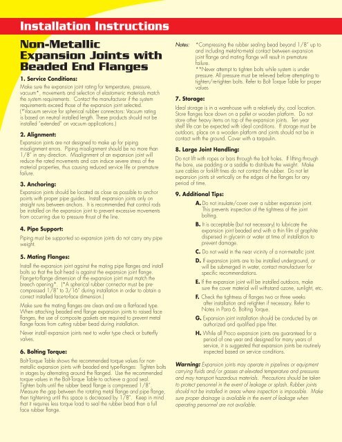
Installation Instructions<br />
Non-Metallic<br />
Expansion Joints with<br />
Beaded End Flanges<br />
1. Service Conditions:<br />
Make sure <strong>the</strong> expansion joint rating for temperature, pressure,<br />
vacuum*, movements and selection of elastomeric materials match<br />
<strong>the</strong> system requirements. Contact <strong>the</strong> manufacturer if <strong>the</strong> system<br />
requirements exceed those of <strong>the</strong> expansion joint selected.<br />
(*Vacuum service for spherical rubber connectors: Vacuum rating<br />
is based on neutral installed length. These products should not be<br />
installed “extended” on vacuum applications.)<br />
2. Alignment:<br />
Expansion joints are not designed to make up for piping<br />
misalignment errors. Piping misalignment should be no more than<br />
1/8” in any direction. Misalignment of an expansion joint will<br />
reduce <strong>the</strong> rated movements and can induce severe stress of <strong>the</strong><br />
material properties, thus causing reduced service life or premature<br />
failure.<br />
3. Anchoring:<br />
Expansion joints should be located as close as possible to anchor<br />
points with proper pipe guides. Install expansion joints only on<br />
straight runs between anchors. It is recommended that control rods<br />
be installed on <strong>the</strong> expansion joint to prevent excessive movements<br />
from occurring due to pressure thrust of <strong>the</strong> line.<br />
4. Pipe Support:<br />
Piping must be supported so expansion joints do not carry any pipe<br />
weight.<br />
5. Mating Flanges:<br />
Install <strong>the</strong> expansion joint against <strong>the</strong> mating pipe flanges and install<br />
bolts so that <strong>the</strong> bolt head is against <strong>the</strong> expansion joint flange.<br />
Flange-to-flange dimension of <strong>the</strong> expansion joint must match <strong>the</strong><br />
breech opening*. (*A spherical rubber connector must be precompressed<br />
1/8” to 3/16” during installation in order to obtain a<br />
correct installed face-to-face dimension.)<br />
Make sure <strong>the</strong> mating flanges are clean and are a flat-faced type.<br />
When attaching beaded end flange expansion joints to raised face<br />
flanges, <strong>the</strong> use of composite gaskets are required to prevent metal<br />
flange faces from cutting rubber bead during installation.<br />
Never install expansion joints next to wafer type check or butterfly<br />
valves.<br />
6. Bolting Torque:<br />
Bolt-Torque Table shows <strong>the</strong> recommended torque values for nonmetallic<br />
expansion joints with beaded end type-flanges: Tighten bolts<br />
in stages by alternating around <strong>the</strong> flanged. Use <strong>the</strong> recommended<br />
torque values in <strong>the</strong> Bolt-Torque Table to achieve a good seal.<br />
Tighten bolts until <strong>the</strong> rubber bead flange is compressed 1/8”.<br />
Measure <strong>the</strong> gap between <strong>the</strong> rotating metal flange and pipe flange,<br />
<strong>the</strong>n tightening until this space is decreased by 1/8”. Keep in mind<br />
that it requires less torque load to seal <strong>the</strong> rubber bead than a full<br />
face rubber flange.<br />
Notes:<br />
7. Storage:<br />
*Compressing <strong>the</strong> rubber sealing bead beyond 1/8” up to<br />
and including metal-to-metal contact between expansion<br />
joint flange and mating flange will result in premature<br />
failure.<br />
**Never attempt to tighten bolts while system is under<br />
pressure. All pressure must be relieved before attempting to<br />
tighten/re-tighten bolts. Refer to Bolt Torque Table for proper<br />
values<br />
Ideal storage is in a warehouse with a relatively dry, cool location.<br />
Store flanges face down on a pallet or wooden platform. Do not<br />
store o<strong>the</strong>r heavy items on top of <strong>the</strong> expansion joints. Ten year<br />
shelf life can be expected with ideal conditions. If storage must be<br />
outdoors, place on a wooden platform and joints should not be in<br />
contact with <strong>the</strong> ground. Cover with a tarpaulin.<br />
8. Large Joint Handling:<br />
Do not lift with ropes or bars through <strong>the</strong> bolt holes. If lifting through<br />
<strong>the</strong> bore, use padding or a saddle to distribute <strong>the</strong> weight. Make<br />
sure cables or forklift tines do not contact <strong>the</strong> rubber. Do not let<br />
expansion joints sit vertically on <strong>the</strong> edges of <strong>the</strong> flanges for any<br />
period of time.<br />
9. Additional Tips:<br />
A. Do not insulate/cover over a rubber expansion joint.<br />
This prevents inspection of <strong>the</strong> tightness of <strong>the</strong> joint<br />
bolting.<br />
B. It is acceptable (but not necessary) to lubricate <strong>the</strong><br />
expansion joint beaded end with a thin film of graphite<br />
dispersed in glycerin or water at time of installation to<br />
prevent damage.<br />
C. Do not weld in <strong>the</strong> near vicinity of a non-metallic joint.<br />
D. If expansion joints are to be installed underground, or<br />
will be submerged in water, contact manufacturer for<br />
specific recommendations.<br />
E. If <strong>the</strong> expansion joint will be installed outdoors, make<br />
sure <strong>the</strong> cover material will withstand ozone, sunlight, etc.<br />
F. Check <strong>the</strong> tightness of flanges two or three weeks<br />
after installation and retighten if necessary. Refer to<br />
Notes in Para 6. Bolting Torque.<br />
G. Expansion joint installation should be conducted by an<br />
authorized and qualified pipe fitter.<br />
H. While all <strong>Proco</strong> expansion joints are guaranteed for a<br />
period of one year and designed for many years of<br />
service, it is suggested that expansion joints be routinely<br />
inspected based on service conditions.<br />
Warning: Expansion joints may operate in pipelines or equipment<br />
carrying fluids and/or gasses at elevated temperature and pressures<br />
and may transport hazardous materials. Precautions should be taken<br />
to protect personnel in <strong>the</strong> event of leakage or splash. Rubber joints<br />
should not be installed in areas where inspection is impossible. Make<br />
sure proper drainage is available in <strong>the</strong> event of leakage when<br />
operating personnel are not available.
Bolt-Torque<br />
PROCO<br />
Nominal<br />
Pipe Size<br />
Expansion<br />
Joint I.D.<br />
<strong>Inc</strong>h /(mm)<br />
1<br />
(25)<br />
1.25<br />
(32)<br />
1.5<br />
(40)<br />
2<br />
(50)<br />
2.5<br />
(65)<br />
3<br />
(80)<br />
3.5<br />
(90)<br />
4<br />
(100)<br />
5<br />
(125)<br />
6<br />
(150)<br />
8<br />
(200)<br />
10<br />
(250)<br />
12<br />
(300)<br />
14<br />
(350)<br />
16<br />
(400)<br />
18<br />
(450)<br />
20<br />
(500)<br />
24<br />
(600)<br />
30<br />
(750)<br />
Step 1<br />
FT-LBS<br />
(Nm)<br />
18<br />
(25)<br />
18<br />
(25)<br />
18<br />
(25)<br />
18<br />
(25)<br />
18<br />
(25)<br />
25<br />
(35)<br />
25<br />
(35)<br />
25<br />
(35)<br />
25<br />
(35)<br />
30<br />
(40)<br />
30<br />
(40)<br />
30<br />
(40)<br />
30<br />
(40)<br />
30<br />
(40)<br />
30<br />
(40)<br />
30<br />
(40)<br />
30<br />
(40)<br />
30<br />
(40)<br />
30<br />
(40)<br />
Rest<br />
30<br />
Min<br />
30<br />
Min<br />
30<br />
Min<br />
30<br />
Min<br />
30<br />
Min<br />
30<br />
Min<br />
30<br />
Min<br />
30<br />
Min<br />
30<br />
Min<br />
30<br />
Min<br />
30<br />
Min<br />
30<br />
Min<br />
30<br />
Min<br />
30<br />
Min<br />
30<br />
Min<br />
30<br />
Min<br />
30<br />
Min<br />
30<br />
Min<br />
30<br />
Min<br />
Bolt-Torque<br />
Step 2<br />
FT-LBS<br />
(Nm)<br />
30<br />
(40)<br />
30<br />
(40)<br />
30<br />
(40)<br />
30<br />
(40)<br />
35<br />
(50)<br />
45<br />
(60)<br />
45<br />
(60)<br />
45<br />
(60)<br />
45<br />
(60)<br />
50<br />
(70)<br />
50<br />
(70)<br />
50<br />
(70)<br />
50<br />
(70)<br />
60<br />
(80)<br />
60<br />
(80)<br />
60<br />
(80)<br />
65<br />
(90)<br />
65<br />
(90)<br />
65<br />
(90)<br />
Note: Bolt torque based on new bolts and nuts<br />
Rest<br />
60<br />
Min<br />
60<br />
Min<br />
60<br />
Min<br />
60<br />
Min<br />
60<br />
Min<br />
60<br />
Min<br />
60<br />
Min<br />
60<br />
Min<br />
60<br />
Min<br />
60<br />
Min<br />
60<br />
Min<br />
60<br />
Min<br />
60<br />
Min<br />
60<br />
Min<br />
60<br />
Min<br />
60<br />
Min<br />
60<br />
Min<br />
60<br />
Min<br />
60<br />
Min<br />
Step 3<br />
FT-LBS<br />
(Nm)<br />
45-60<br />
(60-80)<br />
45-60<br />
(60-80)<br />
45-60<br />
(60-80)<br />
45-60<br />
(60-80)<br />
50-60<br />
(70-80)<br />
60-75<br />
(80-100)<br />
60-75<br />
(80-100)<br />
60-75<br />
(80-100)<br />
60-75<br />
(80-100)<br />
60-75<br />
(80-100)<br />
60-75<br />
(80-100)<br />
75-85<br />
(100-115)<br />
75-85<br />
(100-115)<br />
75-95<br />
(110-130)<br />
75-95<br />
(110-130)<br />
90-95<br />
(120-130)<br />
95-185<br />
(130-250)<br />
95-185<br />
(130-250)<br />
95-220<br />
(130-300)<br />
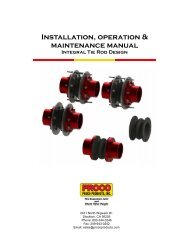
Joints with Beaded End Flanges<br />
Right:<br />
Flanges<br />
with correct<br />
ID help prevent<br />
damage to<br />
rubber.<br />
Right:<br />
Weld neck<br />
flanges with<br />
correct ID<br />
prevent damage<br />
to rubber.<br />
Right:<br />
In case of B, D,<br />
F an additional<br />
metal gasket<br />
can be used to<br />
prevent damage<br />
to rubber.<br />
Right:<br />
Well rounded<br />
smooth edge<br />
prevents<br />
damage to<br />
rubber.<br />
A<br />
C<br />
E<br />
G<br />
Pipe<br />
Stop<br />
Wrong:<br />
Insure mating<br />
flange I.D.<br />
is flush with<br />
rubber.<br />
Wrong:<br />
Uneven end of<br />
pipe can cause<br />
damage to<br />
rubber.<br />
Wrong:<br />
Inner edge<br />
of flanges<br />
damages<br />
rubber.<br />
Tighten opposing nuts/bolts gradually<br />
according to <strong>the</strong> following sequence<br />
B<br />
D<br />
F<br />
The Expansion Joint<br />
and<br />
and Check Check Valve Valve People People<br />
(800) 344-3246 • email: sales@procoproducts.com • www.procoproducts.com