Metallic Expansion Joints - Thorburn Flex Inc
Metallic Expansion Joints - Thorburn Flex Inc
Metallic Expansion Joints - Thorburn Flex Inc

Create successful ePaper yourself
Turn your PDF publications into a flip-book with our unique Google optimized e-Paper software.
THORBURN<br />
FLEXIBLE PIPING SPECIALIST<br />
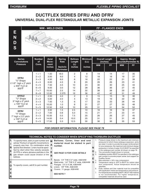
DUCTFLEX SERIES DFRU AND DFRV<br />
UNIVERSAL DUAL-FLEX RECTANGULAR METALLIC EXPANSION JOINTS<br />
E<br />
N<br />
D<br />
S<br />
WW - WELD ENDS<br />
L O.A.L.<br />
L<br />
37.5°<br />
L<br />
FF - FLANGED ENDS<br />
O.A.L.<br />
L<br />
Series Number Axial Spring Bellows Minimum Overall Length Approx. Weight<br />
Convolutions of Move- Rate Length (LL) (inches) (pounds/Perimeter ft)<br />
Pressure Cons. ment (L)<br />
inches lbs/in/in inches inches<br />
Perimeter<br />
WW FF WW FF<br />
DFRU<br />
"U" Shape<br />
2 1/2" high x 2" pitch<br />
± 400" H 2<br />
O at<br />
800ºF<br />
DFRVZ<br />
"U" Shape<br />
5" high x 2" pitch<br />
± 100" H 2<br />
O at<br />
800ºF<br />
DFRV<br />
"V" Shape<br />
7" high x 2.5" pitch<br />
± 100" H 2<br />
O at<br />
800ºF<br />
1 + 1 1.50 18.0 2 8 14 14 17 35<br />
2 + 2 3.00 9.0 4 12 18 18 19 37<br />
3 + 3 4.50 6.0 6 16 22 22 21 39<br />
4 + 4 6.00 4.5 8 20 26 26 23 41<br />
5 + 5 7.50 3.5 10 24 30 30 25 43<br />
6 + 6 9.00 3.0 12 28 36 36 27 45<br />
7 + 7 10.50 2.5 14 32 38 38 29 47<br />
8 + 8 12.00 2.375 16 36 42 42 31 49<br />
1 + 1 2.50 4.0 2 9 15 15 18 36<br />
2 + 2 5.00 2.0 4 13 19 19 22 40<br />
3 + 3 7.50 1.3 6 17 23 23 26 44<br />
4 + 4 10.00 1.0 8 21 27 27 30 48<br />
5 + 5 12.50 0.8 10 25 31 31 34 52<br />
1 + 1 3.50 1.5 2.5 10 16 16 18 37<br />
2 + 2 7.00 0.8 5.0 15 21 21 23 41<br />
3 + 3 10.50 0.5 7.5 20 26 26 27 45<br />
4 + 4 14.00 0.4 10.0 25 31 31 31 49<br />
5 + 5 17.50 0.3 12.5 30 36 36 35 53<br />
FOR ORDER INFORMATION, PLEASE SEE PAGE 78<br />
L<br />
I<br />
N<br />
E<br />
R<br />
C<br />
O<br />
V<br />
E<br />
R<br />
TECHNICAL NOTES TO CONSIDER WHEN SPECIFYING THORBURN DUCTFLEX<br />
To specify liners, add L to part number and<br />
advise <strong>Thorburn</strong> of specific movements to<br />
properly size liner. On combination ends<br />
specify flow direction. Liners must be specified<br />
by client when flow velocity exceeds<br />
25 FPS or where abrasive particles in the<br />
gas stream could cause erosion of the<br />
bellows.<br />
To specify covers, add C to part number.<br />
M<br />
A<br />
T<br />
E<br />
R<br />
I<br />
A<br />
L<br />
S<br />
Bellows: Cover, liner and end<br />
material must be stated in part<br />
number.<br />
SEE PAGE 12 FOR CODE DETAILS<br />
Bands: 1/4" THK X 2" wide, A36/44W<br />
Weld ends: 1/4" THK X 3" wide, A36/44W<br />
Flanges: 3 X 3 X 3/8, A36/44W<br />
Liners: 1/8" THK, A36/44W<br />
Covers: 11 gauge, A36/44W<br />
SEE NOTE 7<br />
N<br />
O<br />
T<br />
E<br />
S<br />
1. Pressure range shown is the maximum and minimum<br />
pressures for which these catalogue expansion joints<br />
are rated. In order to provide the proper reinforcement<br />
for your pressures, the maximum and minimum design<br />
pressures in inches of water (H 2<br />
O) MUST be specified<br />
in the catalogue part number as shown on page 78.<br />
2. The convolution height shown is nominal.<br />
3. Installation position MUST be specified in the catalogue<br />
part number to provide proper center duct support for<br />
Dualflex Series.<br />
4. Max extension = 50% max compression.<br />
5. Temperature rating is -20ºF to 800ºF for carbon steel<br />
duct components. Actual temperature should be<br />
specified.<br />
6. Ends, bellows and liner material must be compatible<br />
with application media and temperature and pressure.<br />
7. For temperatures exceeding 800ºF, MCOT A36 material<br />
is not recommended. For higher temperature,<br />
compatible materials should be used.<br />
Page 79