Distributed Flexible AC Transmission System (D ... - PowerWorld
Distributed Flexible AC Transmission System (D ... - PowerWorld
Distributed Flexible AC Transmission System (D ... - PowerWorld

Create successful ePaper yourself
Turn your PDF publications into a flip-book with our unique Google optimized e-Paper software.
<strong>Distributed</strong> <strong>Flexible</strong> <strong>AC</strong> <strong>Transmission</strong><br />
<strong>System</strong> (D‐F<strong>AC</strong>TS)<br />
Jamie Weber<br />
weber@powerworld.com, 217‐384‐6330 ext. 13<br />
Slide Preparation: Kate Rogers Davis<br />
kate@powerworld.com, 217‐384‐6330, Ext 14<br />
2001 South First Street<br />
Champaign, Illinois 61820<br />
+1 (217) 384.6330<br />
©2013 <strong>PowerWorld</strong> Corporation<br />
support@powerworld.com<br />
http://www.powerworld.com
Outline<br />
• Background<br />
– Power flow control<br />
– F<strong>AC</strong>TS vs. D‐F<strong>AC</strong>TS<br />
• <strong>PowerWorld</strong> D‐F<strong>AC</strong>TS Modeling<br />
– Stand alone operation<br />
– Line impedance sensitivities<br />
– Contingency analysis<br />
• Continuing Work<br />
©2013 <strong>PowerWorld</strong> Corporation<br />
2
Power Flow Control<br />
• Power flow is not directly controllable ‐ to change<br />
the way power flows in the system, we need to be<br />
able to change line impedance, voltage magnitude,<br />
or angle differences<br />
• Benefits<br />
– Relieve overloaded lines<br />
– Reduce transmission losses<br />
– Maintain acceptable voltages<br />
– Improve stability<br />
– Full utilization of existing system<br />
• Limitations<br />
– Cost<br />
– Size and installation<br />
©2013 <strong>PowerWorld</strong> Corporation<br />
3
<strong>Flexible</strong> <strong>AC</strong> <strong>Transmission</strong> <strong>System</strong>s<br />
(F<strong>AC</strong>TS) – IEEE Definitions<br />
• Flexibility<br />
– ability to accommodate changes in the system or<br />
operating conditions without violating stability<br />
margins<br />
• <strong>Flexible</strong> <strong>AC</strong> <strong>Transmission</strong> <strong>System</strong><br />
– incorporates power electronics and other static<br />
controllers to enhance controllability and increase<br />
transfer capability<br />
• F<strong>AC</strong>TS Controller<br />
– provides control of one or more <strong>AC</strong> transmission<br />
system parameter<br />
F<strong>AC</strong>TS Working Group, “Proposed Terms and Definitions for <strong>Flexible</strong> <strong>AC</strong> <strong>Transmission</strong> <strong>System</strong><br />
(F<strong>AC</strong>TS)”, IEEE Transactions on Power Delivery, Vol. 12, Issue 4, October 1997.<br />
©2013 <strong>PowerWorld</strong> Corporation<br />
4
Active Impedance Injection<br />
• The Synchronous Voltage Source (SVS)<br />
+ V COMP - I LINE<br />
Inverter<br />
Device<br />
Control<br />
Signals<br />
Insertion<br />
Transformer<br />
• Injects an <strong>AC</strong> voltage, V COMP<br />
jIm<br />
Inductive Range<br />
V COMP<br />
<br />
I LINE<br />
Capacitive Range<br />
• In practice, V COMP is 90<br />
degrees out of phase<br />
with the line current)<br />
• Otherwise you must<br />
have a power source!<br />
Re<br />
V I Z<br />
comp<br />
Line<br />
jI X or jI X<br />
Line c Line L<br />
• Controls V COMP with respect to I LINE<br />
• Changes effective line impedance<br />
• Many F<strong>AC</strong>TS devices use this concept<br />
©2013 <strong>PowerWorld</strong> Corporation<br />
5
F<strong>AC</strong>TS Technologies<br />
• Static Var Compensator (SVC)<br />
– Thyristor‐controlled capacitors and reactors<br />
– Stability and voltage control<br />
• Thyristor‐Controlled Series Capacitors (TCSC)<br />
or Thyristor‐Switched Series Capacitors (TSSC)<br />
– Thyristor‐controlled capacitors and reactors<br />
– Capacitive or inductive compensation<br />
• Static Synchronous Series Compensator (SSSC)<br />
– Uses a SVS<br />
– Capacitive or inductive compensation<br />
©2013 <strong>PowerWorld</strong> Corporation<br />
6
F<strong>AC</strong>TS Technologies<br />
• Static Synchronous Compensator (STATCOM)<br />
or Static Synchronous Compensator (SSC)<br />
– Uses a SVS<br />
– Analogous to synchronous condensers<br />
• Unified Power Flow Controller (UPFC)<br />
– Combination of STATCOM and SSSC<br />
– Control voltage and real and reactive power flows<br />
• Variable Frequency Transformer (VFT)<br />
– Transfer power between asynchronous grids<br />
– First installation in Quebec, 2004<br />
• And more…<br />
©2013 <strong>PowerWorld</strong> Corporation<br />
7
D‐F<strong>AC</strong>TS Devices<br />
Recently-Introduced <strong>Distributed</strong><br />
F<strong>AC</strong>TS Devices<br />
– Capacitive or inductive<br />
– <strong>Distributed</strong> Static Series<br />
Compensator (DSSC)<br />
– <strong>Distributed</strong> Series Reactor<br />
(DSR) (inductive only)<br />
– Synchronous Voltage Source<br />
– Attach directly to lines<br />
– Small and modular<br />
©2013 <strong>PowerWorld</strong> Corporation<br />
D. Divan, “Improving power line utilization and<br />
performance with D‐F<strong>AC</strong>TS devices,” IEEE PES General<br />
Meeting, June 2005.<br />
8
How can D‐F<strong>AC</strong>TS Improve<br />
Operations<br />
• Exploit the fact that not all locations have<br />
equal impact<br />
• Determine the best locations for the<br />
applications of interest<br />
• Then, determine D‐F<strong>AC</strong>TS settings to achieve<br />
the desired purpose<br />
• Potential applications for D‐F<strong>AC</strong>TS include<br />
– reducing flow through overloaded lines<br />
– minimizing losses<br />
– minimizing cost<br />
©2013 <strong>PowerWorld</strong> Corporation<br />
9
D‐F<strong>AC</strong>TS Technology<br />
• Smart Wire Grid is currently building and<br />
deploying DSRs<br />
• An ARPA‐E project with Smart Wire Grid is<br />
in progress to implement D‐F<strong>AC</strong>TS devices<br />
in software and analyze their benefits to<br />
power systems<br />
©2013 <strong>PowerWorld</strong> Corporation<br />
10
<strong>PowerWorld</strong> D‐F<strong>AC</strong>TS Support<br />
• <strong>PowerWorld</strong> recently added implementation<br />
of the stand‐alone functionality of D‐F<strong>AC</strong>TS<br />
devices, where the value of series reactive<br />
impedance X on the line is set as a function of<br />
the line current.<br />
• This mode of operation for series‐connected<br />
D‐F<strong>AC</strong>TS devices is described in [1] and [2].<br />
[1] H. Johal and D. Divan, “Design considerations for series-connected distributed F<strong>AC</strong>TS<br />
converters,” IEEE Transactions on Industry Applications, vol. 43, no. 6, pp. 1609-1618,<br />
Nov./Dec. 2007.<br />
[2] H. Johal and D. Divan, “Current limiting conductors: A distributed approach for increasing<br />
T&D system capacity and enhancing reliability,” in 2005/2006 IEEE PES <strong>Transmission</strong> and<br />
Distribution Conference and Exhibition, pp.1127-1133, May 2006.<br />
©2013 <strong>PowerWorld</strong> Corporation<br />
11
D‐F<strong>AC</strong>TS Model Inputs<br />
• For each line with D‐F<strong>AC</strong>TS devices, the<br />
user enters the number of modules and the<br />
reactive impedance per module<br />
• The user also specifies values of line<br />
current magnitude I 0 and I lim<br />
– Below I 0 , the D‐F<strong>AC</strong>TS devices are inactive<br />
– Above I lim , the cumulative impedance injection<br />
of the D‐F<strong>AC</strong>TS devices on the line is at its<br />
maximum value<br />
©2013 <strong>PowerWorld</strong> Corporation<br />
12
Inserting D‐F<strong>AC</strong>TS<br />
• On the transmission<br />
line dialog, click on<br />
“D‐F<strong>AC</strong>TS Devices on<br />
the Line” to see the<br />
D‐F<strong>AC</strong>TS settings<br />
©2013 <strong>PowerWorld</strong> Corporation<br />
13
D‐F<strong>AC</strong>TS Operational Profile<br />
• A piecewise linear function of the form shown<br />
below is created and used internally based on the<br />
entered information<br />
x injected<br />
x lim<br />
x 0<br />
I 0<br />
I lim<br />
I line<br />
©2013 <strong>PowerWorld</strong> Corporation<br />
14
D‐F<strong>AC</strong>TS Dialog<br />
Auto-configuration<br />
settings<br />
Current operating<br />
point<br />
Basic<br />
settings<br />
©2013 <strong>PowerWorld</strong> Corporation<br />
15
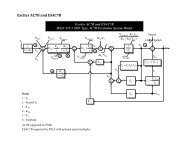
Power Flow Support<br />
• Simulation Solution Process: Three Nested Loops<br />
– MW Control Loop<br />
• Voltage Controller Loop<br />
– Inner Power Flow loop<br />
Traditionally<br />
called the<br />
Power Flow<br />
Voltage<br />
Control<br />
Loop<br />
MW Control<br />
Loop<br />
Generation<br />
Interchange<br />
Control<br />
• <strong>PowerWorld</strong> Simulator implements the control of D‐<br />
F<strong>AC</strong>TS devices in the voltage control loop of the power<br />
flow solution.<br />
• That is, after the inner power flow loop is solved to<br />
determine the state variables, the line current is<br />
calculated, and the D‐F<strong>AC</strong>TS values are adjusted<br />
according to their predefined piecewise linear lookup<br />
functions, if necessary.<br />
• If the D‐F<strong>AC</strong>TS values are changed, an additional power<br />
flow inner loop is solved.<br />
©2013 <strong>PowerWorld</strong> Corporation<br />
16
Line Impedance Sensitivities<br />
• How does a change in line impedance<br />
affect the rest of the system?<br />
• What can be controlled by changing line<br />
impedances?<br />
• What D‐F<strong>AC</strong>TS settings will provide this<br />
control?<br />
©2013 <strong>PowerWorld</strong> Corporation<br />
17
Line Impedance Sensitivities<br />
θ <br />
= <br />
x <br />
<br />
<br />
V<br />
<br />
<br />
State to<br />
Impedance<br />
sensitivity<br />
matrix<br />
<br />
Power Flow to<br />
State sensitivity<br />
matrix<br />
dP P<br />
s<br />
flow, (θ,V) P<br />
flow<br />
<br />
<br />
dx <br />
s(θ,V)<br />
x x<br />
flow, <br />
<br />
<br />
<br />
<br />
<br />
<br />
Power Flow to<br />
Impedance<br />
sensitivity matrix<br />
θ<br />
<br />
P flow, = <br />
<br />
x<br />
V<br />
<br />
<br />
©2013 <strong>PowerWorld</strong> Corporation<br />
18
Single Control Change<br />
New<br />
control<br />
to calculate<br />
Xinj<br />
sensitivities<br />
for DSR<br />
placement<br />
©2013 <strong>PowerWorld</strong> Corporation<br />
19
Multiple Control Change<br />
©2013 <strong>PowerWorld</strong> Corporation<br />
20
Contingency Analysis Results<br />
Monitoring<br />
Use custom<br />
monitors<br />
to monitor<br />
D-F<strong>AC</strong>TS<br />
response<br />
Automatically<br />
limit what<br />
gets<br />
reported<br />
©2013 <strong>PowerWorld</strong> Corporation<br />
21
Contingency Violation Matrices<br />
View DSR<br />
contingency<br />
results<br />
View by<br />
contingency<br />
or by custom<br />
monitor<br />
New tab<br />
showing<br />
DSR results<br />
©2013 <strong>PowerWorld</strong> Corporation<br />
22
Summary<br />
• With the introduction of D‐F<strong>AC</strong>TS devices into<br />
operational systems, <strong>PowerWorld</strong> wants to make it<br />
possible to model their behavior in the system<br />
• <strong>PowerWorld</strong> is taking the first steps to address this<br />
need by<br />
– Added D‐F<strong>AC</strong>TS device objects into the software<br />
– Implemented D‐F<strong>AC</strong>TS device in the power flow<br />
– Added feature to make custom monitoring in contingency<br />
analysis useful<br />
– Also working with Smart Wire Grid and DOE ARPA‐E to<br />
implement D‐F<strong>AC</strong>TS in the OPF solution algorithm<br />
• Kate Rogers Davis<br />
kate@powerworld.com<br />
217‐384‐6330 ext 14<br />
©2013 <strong>PowerWorld</strong> Corporation<br />
23