Drive Solutions for the Global Cement Industry (email) - Tmeic.com
Drive Solutions for the Global Cement Industry (email) - Tmeic.com
Drive Solutions for the Global Cement Industry (email) - Tmeic.com

You also want an ePaper? Increase the reach of your titles
YUMPU automatically turns print PDFs into web optimized ePapers that Google loves.
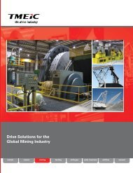
<strong>Drive</strong> <strong>Solutions</strong> <strong>for</strong> <strong>the</strong><br />
<strong>Global</strong> <strong>Cement</strong> <strong>Industry</strong><br />
metals<br />
cranes<br />
mining<br />
testing<br />
oil & gas<br />
solar inverters<br />
utilities<br />
cement
About TMEIC<br />
A <strong>Global</strong> network<br />
TMEIC is built on <strong>the</strong> <strong>com</strong>bined and proud heritage<br />
of Toshiba and Mitsubishi-Electric in <strong>the</strong> industrial<br />
automation, control and drive systems business. TMEIC’s<br />
global business employs more than 2,200 employees,<br />
with sales exceeding U.S. $2.4 billion, and specializes in<br />
Metals, Oil & Gas, Material Handling, Utilities, <strong>Cement</strong>,<br />
Mining, Paper and o<strong>the</strong>r industrial markets.<br />
TMEIC Corporation, headquartered in Roanoke, Virginia,<br />
designs, develops and engineers advanced automation<br />
and variable frequency drive systems.<br />
The factory <strong>for</strong> <strong>the</strong> World’s factories<br />
TMEIC delivers high quality advanced systems and products<br />
to factories worldwide, while serving as a global solutions<br />
partner to contribute to <strong>the</strong> growth of our customers.<br />
Customer Service<br />
At TMEIC, our focus is on <strong>the</strong> customer, working to<br />
provide superior products and excellent service, delivering<br />
customer success every project, every time.<br />
Variable Frequency <strong>Drive</strong>s in <strong>the</strong> <strong>Cement</strong> <strong>Industry</strong><br />
Every step of <strong>the</strong> way, from <strong>the</strong> quarry to <strong>the</strong> finished<br />
cement product, variable frequency drives (VFDs) are<br />
used to smoothly start large motors and continuously<br />
adjust <strong>the</strong> speed as required by <strong>the</strong> process. Induction<br />
and synchronous motors driving excavators, crushers,<br />
conveyors, mills, kilns, and fans use VFDs to provide<br />
high power, speed control, and low-loss flow control with<br />
significant associated energy savings<br />
<strong>Drive</strong>s <strong>for</strong> Conveyors<br />
<strong>Drive</strong>s <strong>for</strong> Mills & Separators<br />
<strong>Drive</strong>s <strong>for</strong> ID Fans<br />
<strong>Drive</strong>s <strong>for</strong> <strong>the</strong> Finish Mill<br />
<strong>Drive</strong>s <strong>for</strong> <strong>the</strong> Kiln<br />
Drawing courtesy Thermo Fisher Scientific Inc.<br />
Controlling fan flow by adjusting speed avoids wasting<br />
energy in adjustable dampers and louvers. When large<br />
flows are involved and <strong>the</strong> motor energy consumption is<br />
significant, varying <strong>the</strong> speed is <strong>the</strong> answer. With large<br />
machines, <strong>the</strong> electrical power savings can amount to<br />
hundreds of thousands of dollars per year. In addition, <strong>the</strong><br />
motors are protected against starting inrush currents, thus<br />
avoiding <strong>the</strong>rmal stress and extending motor life.<br />
Page 2 of 28<br />
© 2011 TMEIC Corporation. All Rights Reserved.
Why Use Electrical Variable Frequency <strong>Drive</strong>s?<br />
Here are some of <strong>the</strong> reasons to use electrical medium voltage drives:<br />
Increased Reliability Pages 5, 5, 9<br />
Variable speed motor-drive systems are more reliable than traditional mechanical approaches such<br />
as using louvers, valves, gears, or turbines to control speed and flow. Because electric drives have<br />
no moving parts, <strong>the</strong>y provide very high reliability, <strong>for</strong> example, <strong>the</strong> Dura-Bilt 5i MV offers a 16 year<br />
MTBF.<br />
Dramatic Energy Savings Pages 4, 5, 10<br />
On an induced draft fan with a variable speed motor-drive system, <strong>the</strong> flow control louver or valve<br />
is not required, avoiding large flow energy losses. In fact, <strong>the</strong> variable speed motor-drive system is<br />
more efficient than all o<strong>the</strong>r flow control methods including turbines and hydraulic transmissions.<br />
For more in<strong>for</strong>mation on this topic, refer to Application 1, and <strong>the</strong> brochure Selecting Variable<br />
frequency drives <strong>for</strong> Flow Control in <strong>the</strong> library at www.tmeic.<strong>com</strong>.<br />
Significantly Less Maintenance Pages 8, 19<br />
The cement plant demands high system availability. Because electric variable speed drive systems<br />
have no moving parts, <strong>the</strong>y require virtually no maintenance. This is in sharp contrast to speed<br />
and flow control devices such as louvers, guide vanes, valves, gears, and turbines that do require<br />
extensive periodic maintenance and associated downtime.<br />
Soft Starting One or Multiple Motors, and Improved Power Factor Pages 8, 9<br />
When electric drives soft start large motors, starting inrush current with associated mechanical and<br />
<strong>the</strong>rmal wiring stress is eliminated. This removes limitations on motor frequency of starts, reduces<br />
insulation damage, and provides extended motor life. With synchronization logic, one drive can<br />
start multiple motors. Finally, large variable frequency drives improve overall system power factor.<br />
Why TMEIC <strong>Drive</strong>s Make Sense<br />
Choose TMEIC, a <strong>Global</strong> Supplier Page 18<br />
TMEIC sells and services drive systems worldwide, supported by engineering and service offices and<br />
spare parts depots in North & South America, Europe, Asia, Japan and Australia.<br />
We’ve got you covered! A Complete Family of <strong>Drive</strong>s Page 19<br />
Our family of low and medium voltage (LV and MV) drives covers all your needs from 450 hp up to<br />
12,000 hp (335 kW to 8,950 kW) and beyond, with a wide output voltage range up to 11 kV, and a line<br />
of DC drives, to meet your requirements.<br />
Engineering Expertise Page 11<br />
TMEIC drive and motor application engineers bring an average of 25 years of practical industry<br />
experience to your application. After analyzing your system requirements, <strong>the</strong>y can re<strong>com</strong>mend <strong>the</strong><br />
most cost effective solution and design <strong>the</strong> <strong>com</strong>plete drive system <strong>for</strong> you.<br />
Configuration Software Pages 19, 20<br />
The TM<strong>Drive</strong> Navigator world-class configuration software is used on all TMEIC drives. Live block<br />
diagrams and tune-up wizards streamline <strong>com</strong>missioning and maintenance activities.<br />
© 2011 TMEIC Corporation. All Rights Reserved. Page 3 of 28
<strong>Drive</strong> Applications <strong>for</strong> Fans, Mills and Kilns<br />
Variable frequency drives are used to control <strong>the</strong> speed of fans, mills, conveyors and kilns in <strong>the</strong> cement industry. VFDs<br />
are also used to smoothly start large mill motors, synchronize, and connect <strong>the</strong>m across <strong>the</strong> line. The following seven<br />
pages describe four typical applications and present <strong>the</strong> reasons why electrical drives were chosen. These applications<br />
are:<br />
1. Induced draft fans<br />
3. Crushers and roller mill drives<br />
2. <strong>Cement</strong> kiln rotation<br />
4. Slip Power Recovery drives<br />
Application 1. Induced Draft Fan <strong>for</strong> <strong>Cement</strong> Kiln<br />
The ID fan induces kiln air flow, which must be continuously varied to match <strong>the</strong> process requirements. Because cement<br />
making is a <strong>the</strong>rmal and a chemical process, both air volume and mass flow must be controlled. The process control system<br />
continuously monitors process conditions such as inlet air temperature, kiln feed, cement <strong>com</strong>position, and required fuelair<br />
ratio. The process control system <strong>the</strong>n directs <strong>the</strong> blower and flow control system to provide <strong>the</strong> optimum air flow.<br />
Traditional flow control methods use constant speed motors with<br />
mechanical flow reducing devices such as:<br />
• Inlet louvers (dampers) in <strong>the</strong> ducting<br />
• Outlet louvers (dampers) in <strong>the</strong> ducting<br />
• Flow guide vanes in <strong>the</strong> fan casing<br />
• Variable slip clutches in <strong>the</strong> fan drive shaft<br />
These mechanical solutions have significant disadvantages:<br />
• High energy consumption at reduced flow rates<br />
• Mechanical wear and required maintenance<br />
• Process interruptions due to mechanical problems<br />
• Limitations on motor starting duty<br />
The electrical solution replaces <strong>the</strong> mechanical equipment with a<br />
Dura-Bilt5i MV VFD. This brings a number of advantages.<br />
Advantages of <strong>the</strong> <strong>Drive</strong> System<br />
Very High Reliability – The Dura-Bilt5i MV uses 3,300 Volt Insulated Gate Bipolar Transistors (IGBT) allowing<br />
a simpler, more reliable inverter design. Since mechanical flow devices are not used, process interruptions<br />
caused by mechanical failures are minimized.<br />
Energy Savings – Elimination of <strong>the</strong> air flow losses through <strong>the</strong> dampers is usually <strong>the</strong> most <strong>com</strong>pelling<br />
reason <strong>for</strong> applying a Dura-Bilt5i MV drive. The ID fan power can be several thousand hp and using a drive<br />
to vary air flow can result in energy savings of over $100,000 per year, as described on <strong>the</strong> next page.<br />
Power System Friendly – The converter is a 24-pulse diode rectifier with a design exceeding <strong>the</strong><br />
requirements of <strong>the</strong> IEEE 519-1992 standard <strong>for</strong> Total Harmonic Distortion (THD). This means that o<strong>the</strong>r<br />
equipment connected to <strong>the</strong> power system is not adversely affected by harmonic frequency disturbances.<br />
Heat Pipe Cooling – The IGBTs in <strong>the</strong> three inverter legs are cooled with heat pipe technology, which<br />
maintains uni<strong>for</strong>m working temperature, prolongs <strong>the</strong> semiconductor life, reduces fan noise, and saves<br />
valuable floor space in <strong>the</strong> plant.<br />
Page 4 of 28<br />
© 2011 TMEIC Corporation. All Rights Reserved.
Energy Savings using a TMEIC Variable Frequency <strong>Drive</strong> Fan System<br />
Variable flow can be provided by varying fan RPM to precisely match process operating conditions. The variable frequency<br />
drive provides variable fan speed which varies <strong>the</strong> air flow according to <strong>the</strong> system resistance.<br />
Main Power<br />
14.4 kV or<br />
below<br />
Dura-Bilt5i MV VFD<br />
(<strong>for</strong> example 1,000 hp)<br />
Variable<br />
Frequency<br />
Three-phase<br />
Induction Motor<br />
Induced Draft Fan<br />
Induced Air Flow<br />
from Kiln<br />
Output Flow<br />
The first chart shows how different fan speeds are<br />
used to select <strong>the</strong> proper operating points A through<br />
E on <strong>the</strong> system resistance curve. Depending upon<br />
<strong>the</strong> size of <strong>the</strong> cement kiln, <strong>the</strong> required ID fan output<br />
power can vary from a few hundred hp to several<br />
thousand hp. The second chart shows a system using<br />
mechanical dampers to achieve flow control. Pairs<br />
of flow and pressure operating points correspond to<br />
points A through E.<br />
Power level percentages shown are total input power<br />
including all motor, trans<strong>for</strong>mer, fan, and system<br />
losses as percentages of required fan output power.<br />
The energy deltas (vertical lines) allow calculation of<br />
energy savings and drive cost justification. A table<br />
of expected annual operating times and power level<br />
differences is shown below. Energy cost factors <strong>for</strong><br />
<strong>the</strong> site are applied and <strong>the</strong> annual savings calculated.<br />
Static Pressure Rise<br />
Operating Point A<br />
140<br />
Pressure Drop and Power<br />
System<br />
Resistance<br />
Speed A<br />
Speed B<br />
Speed C<br />
Speed D<br />
Speed E<br />
Operating Point B<br />
Operating Point C<br />
Operating Point D<br />
Operating Point E<br />
Percent Power<br />
120<br />
100<br />
80<br />
60<br />
40<br />
20<br />
Outlet<br />
Damper<br />
Inlet<br />
Vanes<br />
<strong>Drive</strong><br />
Power<br />
Fan<br />
Output<br />
Flow<br />
Power<br />
Flow<br />
0<br />
20 40 60 80 100<br />
% Flow<br />
Ref<br />
Point<br />
Required<br />
Flow %<br />
% Power Using<br />
Outlet Damper<br />
Control<br />
% Power Using<br />
Adjustable Speed<br />
<strong>Drive</strong><br />
Delta % Power<br />
Saved<br />
% Time on<br />
Annual Basis<br />
% Saved on<br />
Annual<br />
Basis<br />
A 90 120 91 29 15 4.35<br />
B 80 117 66 51 25 12.75<br />
C 70 111 46 65 25 16.25<br />
D 60 103 34 69 20 13.8<br />
E 50 96 23 73 15 10.95<br />
Total Annual % Energy Consumption Savings 58.1<br />
Savings. Based on <strong>the</strong> annualized percent<br />
savings in <strong>the</strong> table, an ID fan system with 1,000<br />
hp output, operating <strong>for</strong> 8,000 of 8,760 hours per<br />
year, at an energy cost of $0.035 per kWh, saves:<br />
1000 x 0.746 x 58.1% x $.035 x 8000 = $121,359<br />
If installed added costs of drive equipment are<br />
$150,000, <strong>the</strong> payback period will be only 15<br />
months. A good return on investment!<br />
© 2011 TMEIC Corporation. All Rights Reserved. Page 5 of 28
Application 2. <strong>Cement</strong> Kiln Speed and Torque Control<br />
In cement plants, variable frequency drives provide controlled torque and speed to <strong>the</strong> kiln. In addition to enhanced<br />
process control, <strong>the</strong> VFD increases <strong>the</strong> life of <strong>the</strong> mechanical equipment and reduces mechanical maintenance and<br />
operating costs. The drives also provide accurate torque and speed feedback signals, which are used by <strong>the</strong> distributed<br />
control system to improve kiln process control.<br />
The cement kiln drive system has a number of per<strong>for</strong>mance<br />
requirements including <strong>the</strong> following:<br />
• 200 to 250% starting torque <strong>for</strong> 60 seconds<br />
• Timed acceleration rate, typically 60 seconds from 0 to top<br />
speed<br />
• Motor current limit protection during starting<br />
• Continuous monitoring of motor loading conditions, with an<br />
alarm output <strong>for</strong> any overload<br />
• Up to 100% continuous operating torque available from 25% to<br />
100% speed<br />
To meet <strong>the</strong>se requirements TMEIC provides both ac and dc drive<br />
technology. With <strong>the</strong> rapid advance of power semiconductors<br />
and ac drive controls in recent years, ac drives are now preferred<br />
over dc drives <strong>for</strong> many kiln applications. Modern drives provide<br />
advanced diagnostic features to simplify troubleshooting and<br />
greatly reduce downtime.<br />
Four TMEIC drive types are usually selected <strong>for</strong> kiln applications:<br />
• TMdrive-10e2 <strong>for</strong> low voltage systems up to 690 V ac<br />
• Dura-Bilt5i MV <strong>for</strong> medium voltage systems up to 4,160 V ac<br />
output<br />
• TMdrive-MVG <strong>for</strong> medium voltage systems up to 6,600 V ac<br />
• TMdrive-DC <strong>for</strong> operating dc motors up to 1,200 V dc<br />
Advantages of <strong>the</strong> VFD Kiln <strong>Drive</strong> System<br />
High Reliability – Advanced design, including use of medium voltage Insulated Gate Bipolar Transistors<br />
(IGBTs) and efficient cooling systems, creates a drive with high reliability and low maintenance.<br />
Heat Pipe Cooling Technology – The TMdrive-10 and Dura-Bilt IGBT power bridges use heat pipe cooling<br />
to move heat to <strong>the</strong> top of <strong>the</strong> cabinet close to <strong>the</strong> fans, <strong>the</strong>reby saving valuable floor space, and reducing<br />
<strong>the</strong> cooling air speed and associated fan noise.<br />
Toolbox Configuration – The Microsoft Windows-based Toolbox software is used to configure, install, and<br />
provide diagnostics. The Toolbox is used by all <strong>the</strong> TMEIC system drives and is a source of productivity <strong>for</strong><br />
<strong>the</strong> life of <strong>the</strong> system. Ei<strong>the</strong>r E<strong>the</strong>rnet or ISBus is used <strong>for</strong> connectivity.<br />
Lan Communications – The selection of LAN options includes ISBus, Profibus-DP, DeviceNet, and<br />
Modbus (E<strong>the</strong>rnet or RTU). These options support virtually all controller plat<strong>for</strong>ms and legacy equipment<br />
allowing seamless integration into new systems.<br />
Page 6 of 28<br />
© 2011 TMEIC Corporation. All Rights Reserved.
Kiln Variable Frequency <strong>Drive</strong> System<br />
Main Power<br />
Three-phase<br />
Variable Frequency<br />
Three-phase<br />
Induction Motor<br />
Gearbox<br />
Kiln roller surface<br />
Kiln drive wheel<br />
<strong>Drive</strong> cabinet<br />
Important Kiln <strong>Drive</strong> Control Requirements are provided by <strong>the</strong> VFD<br />
1. Controlled Acceleration<br />
The controlled and timed acceleration provided by a variable<br />
frequency drive is very beneficial <strong>for</strong> <strong>the</strong> kiln, <strong>com</strong>pared to<br />
starting <strong>the</strong> kiln motor directly from <strong>the</strong> AC line. Rapid, across<strong>the</strong>-line<br />
starting of <strong>the</strong> kiln motor could result in unwanted<br />
torsional oscillations and stresses in parts of <strong>the</strong> driven<br />
machinery.<br />
For example, a typical kiln could easily be accelerated to top<br />
speed in 2 to 3 seconds if <strong>the</strong> motor were permitted to do so.<br />
But <strong>the</strong> kiln’s long cylindrical tube, large reduction gear, and<br />
its associated mechanisms would be subjected to excessive<br />
stresses and perhaps damage. A precisely controlled, timed<br />
kiln acceleration provided by <strong>the</strong> VFD, helps extend <strong>the</strong><br />
mechanical equipment life, and maintain consistent product<br />
output.<br />
2. Controlled Starting Torque<br />
The starting torques typically required <strong>for</strong> a normal kiln are 125<br />
to 175% of motor rated torque assuming <strong>the</strong> following:<br />
• There are no clinker rings<br />
• There are no mud rings<br />
• The idler rolls are properly aligned<br />
• There is normal lubrication <strong>for</strong> all of <strong>the</strong> kiln’s supporting<br />
idler rolls and gears<br />
• The charge in <strong>the</strong> kiln is at <strong>the</strong> minimum elevation (<strong>the</strong> “6<br />
o’clock” position.)<br />
The effects of clinker rings, mud rings on wet process kilns,<br />
and misaligned or poorly lubricated idler rolls (especially<br />
when cold) are to increase <strong>the</strong> starting torques needed from<br />
175 to 225%. This has led to <strong>the</strong> practice of specifying 200%<br />
or greater starting torque <strong>for</strong> 60 seconds. Starting torques are<br />
often specified to be as high as 250% of motor rated torque <strong>for</strong><br />
60 seconds. This gives more margin to assure kiln breakaway<br />
from rest under all anticipated conditions.<br />
3. Feedback to <strong>the</strong> Process Control System<br />
A variable frequency drive provides a very useful<br />
torque or kW feedback signal to help improve<br />
kiln process control. The kiln torque provides<br />
<strong>the</strong> earliest warning of conditions such as a flush<br />
<strong>com</strong>ing through <strong>the</strong> kiln, a clinker ring beginning<br />
to break up, or a mechanical problem such as an<br />
idler roll bearing developing major friction.<br />
Automatic kiln control systems often use a<br />
filtered torque signal and its rate of change as<br />
part of <strong>the</strong> logic <strong>for</strong> controlling <strong>the</strong> kiln and its<br />
operating speed. There<strong>for</strong>e, a good noise-free<br />
torque signal is critical, and is available from <strong>the</strong><br />
TMEIC drive products.<br />
The VFD also provides a kiln speed analog output<br />
signal which, toge<strong>the</strong>r with torque, is sent to <strong>the</strong><br />
process control system.<br />
© 2011 TMEIC Corporation. All Rights Reserved. Page 7 of 28
Application 3. Starting Multiple Mill Motors<br />
Customer installations at two adjacent cement plants use variable frequency drives <strong>for</strong> a number of applications. At <strong>the</strong>se<br />
plants, eight motors ranging from 250 to 2,400 hp are driven by TMEIC medium voltage drives, and <strong>the</strong>re are six large mill<br />
motors, each one requiring a medium voltage motor of 4,000 hp size.<br />
The cement <strong>com</strong>pany had several requirements<br />
when selecting <strong>the</strong>ir six large mill motors, and<br />
associated drives and controls, including:<br />
• Ability to soft start any of <strong>the</strong> motors from<br />
any drive and reduce <strong>the</strong> impact on <strong>the</strong><br />
power system.<br />
• Ability to synchronize <strong>the</strong> motors with <strong>the</strong><br />
utility supply and run some or all of <strong>the</strong><br />
motors on <strong>the</strong> utility supply at constant<br />
speed.<br />
• Ability to run one motor at variable speed<br />
to allow grinding process optimization<br />
• Use synchronous motors, because<br />
synchronous motors can supply leading<br />
VARs to <strong>the</strong> power supply system to help<br />
correct poor plant power factor.<br />
Synchronous Motor <strong>for</strong> Mill<br />
After reviewing <strong>the</strong>ir alternatives, <strong>the</strong> <strong>com</strong>pany<br />
decided to install a TMEIC VFD in each plant to<br />
individually soft start <strong>the</strong> three mill motors. In<br />
addition, since <strong>the</strong> two plants are adjacent, it<br />
was decided to install a tie contactor allowing<br />
any VFD to start any mill motor in ei<strong>the</strong>r plant,<br />
providing backup in case of any problems.<br />
Benefits of <strong>the</strong> Variable Frequency <strong>Drive</strong> and Synchronous Motors<br />
Cost Savings – The customer’s analysis indicated excellent savings by using synchronous motors because<br />
<strong>the</strong>y correct <strong>the</strong> power factor <strong>for</strong> <strong>the</strong> whole plant, and <strong>the</strong>y have a high efficiency. In this location <strong>the</strong> utility<br />
charges users a penalty <strong>for</strong> low power factor operation.<br />
High Reliability – The VFD has a proven history of high reliability. Sharing <strong>the</strong> two VFDs between <strong>the</strong> six<br />
motors using power switches yields an availability of better than 99.999%.<br />
Smooth Motor Starting – The VFD controls <strong>the</strong> rotor field (through <strong>the</strong> exciter) and <strong>the</strong> stator current to<br />
provide a smooth starting profile without exceeding rated volts and amps, <strong>the</strong>reby protecting <strong>the</strong> motor<br />
against overheating. Controlling <strong>the</strong> motor current is also important where power system grids are weak<br />
or <strong>the</strong> plant is at <strong>the</strong> end of a long transmission line. In addition to starting, <strong>the</strong> VFD provides smooth<br />
motor synchronizing with <strong>the</strong> supply.<br />
Page 8 of 28<br />
© 2011 TMEIC Corporation. All Rights Reserved.
Multiplexing Two <strong>Drive</strong>s to Start and Control Six Large Motors<br />
Plant 1<br />
Starting<br />
VFD<br />
Isolation<br />
Contactor<br />
Starting<br />
Contactors<br />
Mill<br />
Motors<br />
VFD Motor<br />
Exciters<br />
34.5 KV<br />
4160 V<br />
VFD<br />
IC1<br />
M1<br />
M2<br />
M3<br />
Run Breakers<br />
ST1<br />
ST2<br />
ST3<br />
MTR1<br />
MTR2<br />
MTR3<br />
EX1<br />
EX2<br />
EX3<br />
Excitation<br />
Voltage<br />
Controller<br />
Excitation<br />
Voltage<br />
Controller<br />
Excitation<br />
Voltage<br />
Controller<br />
Plant 2<br />
34.5 KV<br />
4160 V<br />
VFD<br />
IC2<br />
M4<br />
M5<br />
M6<br />
TC - Tie<br />
Contactor<br />
ST4<br />
ST5<br />
ST6<br />
MTR4<br />
MTR5<br />
MTR6<br />
EX4<br />
EX5<br />
EX6<br />
Excitation<br />
Voltage<br />
Controller<br />
Excitation<br />
Voltage<br />
Controller<br />
Excitation<br />
Voltage<br />
Controller<br />
Redundant <strong>Drive</strong> Starting System Ensures Availability<br />
All six mills are driven by synchronous motors of identical<br />
ratings. One VFD can start any of <strong>the</strong> three motors in<br />
any desired sequence as shown by <strong>the</strong> blue lines in<br />
<strong>the</strong> figure. Once <strong>the</strong> synchronous motor is started, <strong>the</strong><br />
VFD synchronizes <strong>the</strong> motor with <strong>the</strong> supply to operate<br />
directly across <strong>the</strong> line.<br />
As soon as <strong>the</strong> first mill motor is started and bypassed to<br />
<strong>the</strong> line, <strong>the</strong> VFD is available to start <strong>the</strong> second mill. The<br />
same process is repeated to make <strong>the</strong> VFD available <strong>for</strong><br />
starting <strong>the</strong> third mill.<br />
All three mills can operate directly across <strong>the</strong> line,<br />
or one can remain connected to <strong>the</strong> VFD <strong>for</strong> variable<br />
speed operation if required. This system saves on <strong>the</strong><br />
customer’s capital cost.<br />
The VFD is responsible <strong>for</strong> <strong>the</strong> actual phase and voltage<br />
matching <strong>for</strong> <strong>the</strong> final transfer of <strong>the</strong> motor to utility<br />
operation. This transition is coordinated to within a few<br />
milliseconds to prevent damaging torques or loss of<br />
motor synchronization.<br />
© 2011 TMEIC Corporation. All Rights Reserved. Page 9 of 28
Application 4. Energy Savings using Slip Power Recovery <strong>Drive</strong> System<br />
Wound rotor induction motors have been popular in<br />
some industries, particularly cement, <strong>for</strong> decades. Until<br />
about 1985, a wound rotor induction motor (WRIM) was<br />
<strong>the</strong> only large ac motor that allowed controlled starting<br />
characteristics and adjustable speed capability.<br />
A WRIM is a machine with a 3-phase wound stator that<br />
is usually connected directly to <strong>the</strong> power system. The<br />
rotor also has a 3-phase winding, usually connected in<br />
a wye (or star) circuit. The three terminals of <strong>the</strong> rotor<br />
winding are connected to separate slip rings, which are<br />
normally connected to a liquid rheostat or resistor bank.<br />
Changing rotor resistance changes <strong>the</strong> motor speed. In<br />
<strong>the</strong> past <strong>the</strong> power in <strong>the</strong> resistor was lost as heat. The<br />
slip power recovery drive, TMdrive-10SPR, discussed on<br />
page 26, is used to vary <strong>the</strong> motor speed by varying <strong>the</strong><br />
power taken off <strong>the</strong> rotor and returned to <strong>the</strong> utility supply.<br />
The example below <strong>com</strong>pares <strong>the</strong> case of an induction<br />
motor driven by a large standard drive, with <strong>the</strong> case of a<br />
WRIM controlled by a small SPR drive, and calculates <strong>the</strong><br />
energy savings. In <strong>the</strong> larger standard drive system, all<br />
<strong>the</strong> motor power passes through <strong>the</strong> drive. With <strong>the</strong> SPR<br />
drive, only a fraction of <strong>the</strong> motor power passes through<br />
<strong>the</strong> drive.<br />
For a rated fan load of 5,000 hp, running at 90% speed,<br />
<strong>the</strong> power saving using <strong>the</strong> SPR drive is 88 kW. With an<br />
electrical cost of 5¢/kWh, <strong>the</strong> annual savings amount to<br />
$38,540. At lower speeds <strong>the</strong> savings are even higher.<br />
P1<br />
Utility supply<br />
power flow<br />
P5<br />
Slip power recovery<br />
flow after trans<strong>for</strong>mer<br />
Induction<br />
Motor<br />
Standard <strong>Drive</strong><br />
(larger drive)<br />
P2 Power flow to<br />
motor stator<br />
P1<br />
Utility<br />
supply<br />
power flow<br />
P2 Power flow to<br />
motor stator<br />
P4<br />
Trans<strong>for</strong>mer<br />
Power flow<br />
to SPR<br />
TMdrive-10SPR<br />
(smaller drive)<br />
Fan<br />
load<br />
P3<br />
Pump shaft<br />
power flow<br />
P2 = P1 - <strong>Drive</strong> losses<br />
P3 = P2 - Motor losses<br />
Wound Rotor<br />
Induction Motor<br />
Fan<br />
load<br />
P3<br />
Pump<br />
shaft<br />
power<br />
flow<br />
P2 = P1 + P5<br />
P4 = P2 - P3 - Motor Losses<br />
P5 = P4 - <strong>Drive</strong> & Tfmr Losses<br />
Standard <strong>Drive</strong> & Induction Motor<br />
Slip Power Recovery <strong>Drive</strong> and Wound Rotor Motor<br />
Operating Conditions<br />
Power<br />
Flow<br />
Standard <strong>Drive</strong> &<br />
Induction Motor<br />
Slip Power Recovery <strong>Drive</strong><br />
and Wound Rotor Motor<br />
Fan Load at Full Speed, shaft kW<br />
—<br />
3730 kW (5,000 hp)<br />
3730 kW (5,000 hp)<br />
Fan Load at 90% Speed, shaft kW<br />
P3<br />
2720 kW<br />
2720 kW<br />
Utility supply power flow<br />
P1<br />
2980 kW<br />
2892 kW<br />
Power flow to motor stator<br />
P2<br />
2863 kW<br />
3180 kW<br />
Power flow to Slip power recovery drive<br />
P4<br />
0<br />
300 kW<br />
Slip power recovery after trans<strong>for</strong>mer<br />
P5<br />
0<br />
288 kW<br />
Difference in utility power flows P1(IM)-P1(SPR)<br />
—<br />
—<br />
88 kW<br />
SPR system savings with 5¢/kWH electrical power<br />
—<br />
—<br />
$38,540 per year<br />
Page 10 of 28<br />
© 2011 TMEIC Corporation. All Rights Reserved.
Project Engineering<br />
TMEIC’s <strong>Cement</strong> Engineering <strong>Drive</strong> Team in Virginia<br />
Experienced <strong>Drive</strong> Engineering Team<br />
The drive engineering team is experienced in <strong>the</strong><br />
cement industry and gained its experience working in<br />
<strong>the</strong> plants with technicians and mechanical suppliers.<br />
This engineering background, coupled with state-of-<strong>the</strong>art<br />
technology, enables TMEIC to consistently meet <strong>the</strong><br />
demanding requirements of <strong>the</strong> industry.<br />
Experienced drive engineers jointly define <strong>the</strong> drive<br />
equipment and control strategy with your engineers<br />
and <strong>the</strong> OEM. This is followed by detailed design of <strong>the</strong><br />
system, control logic, and configuration of <strong>the</strong> drives.<br />
Project Life Cycle Process Minimizes Risk<br />
We understand that delay in <strong>com</strong>missioning is very<br />
expensive, so we take steps to hold our startup schedule:<br />
• Project management provides a single point of contact<br />
from initial order to final <strong>com</strong>missioning<br />
• Complete factory tests include applying power to <strong>the</strong><br />
bridges and exercising <strong>the</strong> control<br />
• The local <strong>com</strong>missioning engineers are included in<br />
<strong>the</strong> project team, allowing a seamless transition from<br />
<strong>the</strong> factory to your plant<br />
Local Commissioning Team Ensures Knowledgeable<br />
Ongoing Service<br />
Our field service organization is broad and deep with<br />
extensive experience in <strong>the</strong> industry providing you with<br />
a strong local service presence <strong>for</strong> startup and ongoing<br />
service work, both in North America and overseas.<br />
© 2011 TMEIC Corporation. All Rights Reserved. Page 11 of 28
We Engineer <strong>the</strong> Medium Voltage Power System<br />
TMEIC application engineers design <strong>the</strong> power system from <strong>the</strong> medium voltage switchgear to <strong>the</strong> adjustable speed drive<br />
and motor. The critical engineering process <strong>for</strong> a successful installation is illustrated in <strong>the</strong> chart (top page 14) and detailed<br />
in this Project Engineering section. Icons indicate where <strong>the</strong> various teams of engineers in <strong>the</strong> factory and field service<br />
are involved in <strong>the</strong> project.<br />
A typical MV power system is shown below. TMEIC Application Engineers size and select all <strong>the</strong> equipment <strong>for</strong> <strong>the</strong> optimal<br />
drive solution.<br />
Medium Voltage Power System<br />
MV switchgear is selected <strong>for</strong> <strong>the</strong><br />
application considering:<br />
- The type, such as vacuum or SF6<br />
- The size <strong>for</strong> <strong>the</strong> current and voltage<br />
- The CTs, PTs, and protective relays<br />
to operate <strong>the</strong> breaker<br />
- The enclosure <strong>for</strong> outdoor or indoor<br />
- The environment such as temperature<br />
and humidity<br />
Instrumentation <strong>for</strong> equipment<br />
metering, monitoring, protection<br />
and control is selected, including:<br />
- Amp transducer and ammeter<br />
- Watt and Watt-hour transducers<br />
- Phase CTs and phase overcurrent<br />
relay<br />
- Ground sensor CT and relay<br />
- Power quality monitor<br />
<strong>Drive</strong> isolation, input and output,<br />
trans<strong>for</strong>mers are selected <strong>for</strong> <strong>the</strong><br />
application considering:<br />
- The type, such as dry or liquid filled<br />
- Size <strong>for</strong> <strong>the</strong> kVA and voltage<br />
- Cooling if required<br />
- The enclosure <strong>for</strong> outdoor or indoor<br />
- The environment such as temperature<br />
and humidity<br />
- Special drive requirements<br />
Page 12 of 28<br />
© 2011 TMEIC Corporation. All Rights Reserved.
Selection of <strong>the</strong> best adjustable speed<br />
drive <strong>for</strong> <strong>the</strong> application based on:<br />
- Continuous and overload torque<br />
and power requirements<br />
- Type of load, including constant<br />
or variable torque or regenerative<br />
- <strong>Drive</strong> and motor voltage<br />
- Power system <strong>com</strong>patibility<br />
- Overall efficiency of <strong>the</strong> ASD and<br />
motor <strong>com</strong>bination<br />
- Harmonic analysis<br />
Selection of optional drive<br />
associated equipment such as:<br />
- PLC <strong>for</strong> logic control, <strong>for</strong> example<br />
synchronizing multiple motors with<br />
<strong>the</strong> supply <strong>for</strong> soft start capability<br />
- Air conditioned equipment house if<br />
required<br />
- Switchgear if motor is to be<br />
synchronized with <strong>the</strong> line<br />
- Reactor <strong>for</strong> use with an LCI<br />
Selection of <strong>the</strong> motor and associated<br />
equipment including:<br />
- Induction, synchronous, or wound rotor<br />
motor<br />
- Motor size including <strong>the</strong> power, torque,<br />
voltage, current, and speed<br />
- Selection of <strong>the</strong> exciter if a synchronous<br />
motor is used<br />
- Required motor protection devices<br />
- Optional tachometer-special applications<br />
- Torsional analysis<br />
© 2011 TMEIC Corporation. All Rights Reserved. Page 13 of 28
Project Life Cycle Process<br />
The Project Teams<br />
Technical<br />
Proposal<br />
Specification<br />
Detailed<br />
Hardware &<br />
Software Design<br />
and Component<br />
Procurement<br />
Factory<br />
Acceptance<br />
Test<br />
System<br />
Commissioning<br />
System<br />
Maintenance<br />
and Service<br />
Customer Team<br />
Field Team<br />
Factory Team<br />
Training Team<br />
Technical Proposal Specification<br />
TMEIC Assists in <strong>the</strong> Project Planning<br />
Utility Voltage bus<br />
PLC Coordination<br />
& Interface<br />
DB5i MV Unit A<br />
Sync Ready<br />
DB5i MV Unit B<br />
Sync Ready<br />
3-phase<br />
3-phase<br />
Tie Contactor<br />
VFD Bus<br />
1 CPT<br />
2 PTs<br />
Mtr 1 Mtr 2 Mtr 3<br />
Bypass Bus<br />
CT-1 CT-4 CT-5<br />
During all phases of your project<br />
planning, TMEIC assists by<br />
supplying in<strong>for</strong>mation, training,<br />
guide-<strong>for</strong>m specifications, and<br />
general advice. Experienced drive<br />
application engineers prepare a<br />
technical proposal that includes:<br />
• Customized system architecture<br />
<strong>for</strong> your project.<br />
• Detailed equipment<br />
specifications <strong>for</strong> <strong>the</strong> drives,<br />
exciters, trans<strong>for</strong>mers,<br />
switchgear, and housings.<br />
• Thorough description of <strong>the</strong><br />
PLC control functions, including<br />
logic <strong>for</strong> synchronizing and desynchronizing<br />
<strong>the</strong> motors.<br />
• Formal bid documentation.<br />
Page 14 of 28<br />
Detailed description of<br />
equipment in proposal<br />
© 2011 TMEIC Corporation. All Rights Reserved.<br />
System architecture illustration
Detailed Hardware/Software Design & Procurement<br />
Electrical and<br />
mechanical prints<br />
Control logic and<br />
drive configuration<br />
Keypad<br />
configuration<br />
Based on <strong>the</strong> proposal specification, <strong>the</strong> project engineering team proceeds with four main tasks:<br />
• Control Software Design. Control engineers configure <strong>the</strong> drives and PLC controller logic, if a PLC is required <strong>for</strong> <strong>the</strong><br />
application. The illustration above shows a typical toolbox logic function diagram in Relay Ladder Diagram <strong>for</strong>mat.<br />
The toolbox is used <strong>for</strong> drive configuration, tuning, sequencing, and drive diagnostics.<br />
• Optional HMI Screen Design. Interface screens <strong>for</strong> maintenance and drive control are configured using <strong>the</strong> touch<br />
panel engineering tools. These screens provide real-time drive data and operator interaction.<br />
• Hardware Design. All equipment is specified per <strong>the</strong> project requirements, and a <strong>com</strong>plete set of elementary diagrams,<br />
layout, and outline drawings is created.<br />
• Component Procurement. We work with our parent <strong>com</strong>panies to source <strong>the</strong> most cost effective system <strong>com</strong>ponents<br />
<strong>for</strong> your application.<br />
© 2011 TMEIC Corporation. All Rights Reserved. Page 15 of 28
System Test<br />
TMEIC understands <strong>the</strong> importance<br />
of a thorough system test. Our<br />
engineering team conducts a<br />
<strong>com</strong>prehensive factory test be<strong>for</strong>e<br />
shipment.<br />
For example, <strong>the</strong> Dura-Bilt5i MV<br />
drive tests in <strong>the</strong> factory include:<br />
• Full voltage check of power cells,<br />
insulation, and control circuits<br />
• Acceleration and run test with<br />
unloaded MV motor<br />
• Full current test into a reactor<br />
• Validation of all I/O interfaces<br />
• Validation of <strong>the</strong> drive test<br />
modes and any special logic, or<br />
optional PLC<br />
Dura-Bilt 5i MV <strong>Drive</strong> Factory Test<br />
Dura-Bilt 5i MV Control System Validation in <strong>the</strong> Factory<br />
Toolbox Software <strong>for</strong> <strong>Drive</strong><br />
and Logic Configuration<br />
Operator's Keypad<br />
<strong>Drive</strong> Control<br />
Logic Control<br />
Firing Boards<br />
LAN Interface<br />
DB5i Controller<br />
Simulation Software<br />
<strong>Drive</strong> Simulator<br />
Optional PLC with<br />
Logic, <strong>for</strong> example,<br />
<strong>for</strong> soft start of<br />
multiple motors<br />
Diagram of Dura-Bilt Control System Test Setup<br />
M<br />
Load<br />
Local Area Network to DCS<br />
U<br />
P<br />
C<br />
Digital Motor<br />
Simulator<br />
Digital Load<br />
Simulator<br />
PLC<br />
I/O modules<br />
Factory validation of <strong>the</strong> drive<br />
control system is available as<br />
an option, ei<strong>the</strong>r in Roanoke,<br />
Virginia, or in Houston, Texas.<br />
Validation of <strong>the</strong> optional<br />
LAN interface, DCS link,<br />
and PLC sequencing and<br />
logic can be done as shown<br />
opposite. <strong>Drive</strong>, motor, and<br />
load simulators are available if<br />
required. Using <strong>the</strong> simulated<br />
equipment, <strong>the</strong> PLC can be<br />
run through its sequencing<br />
and <strong>the</strong> resulting outputs<br />
validated.<br />
Note: Logic <strong>for</strong> synchronizing<br />
a single motor to <strong>the</strong> line can<br />
be included in <strong>the</strong> Dura-Bilt5i<br />
controller, so a PLC is not<br />
required <strong>for</strong> this.<br />
Page 16 of 28<br />
© 2011 TMEIC Corporation. All Rights Reserved.
System Commissioning<br />
In <strong>the</strong> <strong>com</strong>missioning phase, <strong>the</strong> TMEIC team includes <strong>the</strong><br />
field engineers you know and trust, alongside <strong>the</strong> engineer<br />
who designed and tested <strong>the</strong> system. This overlap of teams<br />
between engineering design and <strong>the</strong> site ensures a smooth<br />
and on-schedule startup.<br />
The TMEIC service engineer, who is responsible <strong>for</strong> startup<br />
and <strong>com</strong>missioning, and <strong>for</strong> any future service required at<br />
<strong>the</strong> site, is part of <strong>the</strong> project team and participates in <strong>the</strong><br />
factory system test to be<strong>com</strong>e familiar with <strong>the</strong> system.<br />
Commissioning is supported by TMEIC design and service<br />
engineers.<br />
<strong>Drive</strong> Training at <strong>the</strong> Factory or in Your Plant<br />
Customer engineers, maintenance and operations<br />
personnel are trained on <strong>the</strong> drives and control system<br />
at <strong>the</strong> TMEIC Training Center in Virginia. This worldclass<br />
facility features large classrooms and fullyequipped<br />
training labs.<br />
Classroom and hands-on training consists of 50% class<br />
time and 50% hands-on lab time. Topics include:<br />
• Overview of <strong>the</strong> drive system<br />
• Function of <strong>the</strong> main assemblies<br />
• Technical details of <strong>the</strong> <strong>com</strong>ponents<br />
• <strong>Drive</strong> and control system tools<br />
• System diagnostics and service<br />
As an alternative to <strong>the</strong> standard factory training in<br />
Virginia, TMEIC can offer a course tailored to your<br />
project and held at your location. In this case, a<br />
project engineer trains your operators, maintenance<br />
technicians and engineers in your facility.<br />
Complete and Detailed <strong>Drive</strong> System Documentation<br />
Along with <strong>the</strong> hardware and software, TMEIC<br />
delivers <strong>com</strong>plete system documentation:<br />
• An electronic instruction book with all <strong>the</strong><br />
prints on CD with a hyperlink index<br />
• Re<strong>com</strong>mended wiring and grounding<br />
procedures<br />
• Renewal parts list<br />
• Standard third-party vendor documentation<br />
At <strong>the</strong> end of <strong>the</strong> project, <strong>the</strong> drawings are<br />
updated to reflect <strong>the</strong> final changes.<br />
© 2011 TMEIC Corporation. All Rights Reserved. Page 17 of 28
<strong>Global</strong> Customer Support Network<br />
System Maintenance & Service<br />
Comprehensive technical service is provided by our Customer Support Organization, staffed by TMEIC service engineers<br />
with offices and spare parts depots across <strong>the</strong> globe.<br />
In North and South America<br />
Customers are supported by <strong>the</strong> TMEIC Corporation<br />
service personnel, design engineers and Spare Parts<br />
Depot in Virginia, and <strong>the</strong> TMEIC Factory in Japan.<br />
In Europe<br />
TMEIC service engineers service all drive systems<br />
in Europe, supported by <strong>the</strong> European TMEIC Spare<br />
Parts Depot.<br />
In Asia and <strong>the</strong> Pacific Rim<br />
TMEIC services drive systems throughout China,<br />
India and <strong>the</strong> Pacific Rim, supported by multiple<br />
Field Engineers, Spare Parts Depots, and <strong>the</strong> TMEIC<br />
factory in Japan.<br />
Remote <strong>Drive</strong> Diagnostics<br />
TMEIC Corporation supports drive customers<br />
through <strong>the</strong> Remote Connectivity Module (RCM), a<br />
remote diagnostic service link with <strong>the</strong> TMEIC design<br />
and service engineers in Roanoke, Virginia. The RCM<br />
enables seamless integration between your drives<br />
and our engineers.<br />
Remote System Diagnostics<br />
TMEIC’s remote system diagnostics tool, included<br />
in level 1 software, offers a quick path to problem<br />
resolution. System faults are automatically identified,<br />
and provide an integrated view of product, process<br />
and system in<strong>for</strong>mation. TMEIC design and service<br />
engineers in Roanoke, Virginia, can analyze <strong>the</strong> data<br />
and provide steps <strong>for</strong> resolution.<br />
For Service or Parts, call<br />
1-877-280-1835<br />
INTERNATIONAL:<br />
+1-540-283-2010<br />
24 Hours / 7 days<br />
Remote Diagnostic Service reduces Mean Time To Repair (MTTR)<br />
Remote diagnostic service offers protection <strong>for</strong> your investment, by reducing downtime, lowering repair costs and<br />
providing peace of mind. Remote diagnostics requires an internet connection between your plant and TMEIC Corporation<br />
<strong>for</strong> retrieval of fault logs and files to diagnose drive or system issues.<br />
Features<br />
• Reduced downtime and<br />
Mean-Time-to-Repair<br />
• Secured connection<br />
• Fault Upload Utility<br />
Benefits<br />
Quick support saves thousands of $ in lost production<br />
TMEIC engineers can quickly connect to <strong>the</strong> drive and diagnose many issues in a<br />
matter of minutes.<br />
Customer-controlled access<br />
All remote activity is conducted with permission of <strong>the</strong> customer. <strong>Drive</strong> start/stop<br />
is not permitted remotely.<br />
Proprietary Fault Upload Software<br />
Historical drive faults are identified; TMEIC design and service engineers can<br />
analyze <strong>the</strong> issue resulting in <strong>the</strong> fault and provide a solution.<br />
Page 18 of 28<br />
© 2011 TMEIC Corporation. All Rights Reserved.
A Family of <strong>Drive</strong>s up to 11 kV<br />
TMdrive-10e2<br />
TMdrive-10SPR<br />
Dura-Bilt5i MV<br />
TMdrive-DC<br />
TMdrive-MVG<br />
TMdrive-XL55<br />
Power Rating of AC and DC <strong>Drive</strong> Family<br />
Medium<br />
Voltage<br />
Medium<br />
Voltage<br />
Medium<br />
Voltage<br />
(MV motor with LV Slip Power Recovery drive)<br />
TMdrive-XL55<br />
TMdrive-MVG<br />
Dura-Bilt5i MV<br />
TMdrive-10SPR<br />
Low<br />
Voltage<br />
DC<br />
Voltage<br />
TMdrive-10e2<br />
TMdrive-DC<br />
20<br />
27<br />
40<br />
54<br />
100<br />
134<br />
200 300 400 1,000 2,000<br />
268 402 536<br />
1,340 2,682<br />
4,000<br />
5,364<br />
10,000<br />
13,400<br />
20,000<br />
26,820<br />
kW<br />
Hp<br />
TMEIC Family of Medium Voltage AC System <strong>Drive</strong>s<br />
Over 50 Years <strong>Drive</strong> Experience. Starting with DC drives,<br />
we later added AC drives, such as <strong>the</strong> Innovation Series<br />
drives and <strong>the</strong> new technology Tosvert, Dura-Bilt, and<br />
TMdrives. Since 1979 over 2 million hp of TMEIC and<br />
GE AC drives have been installed and are in service,<br />
representing <strong>the</strong> largest installed base of MV drives of<br />
any manufacturer.<br />
<strong>Drive</strong> Voltages up to 11 kV. The family of drives offers<br />
voltages all <strong>the</strong> way from 440 V with <strong>the</strong> TMdrive-10e2<br />
up to 11 kV with <strong>the</strong> TMdrive-MVG.<br />
The Highest Reliability. TMEIC drives provide <strong>the</strong><br />
highest reliability based on field experience and<br />
customer satisfaction surveys.<br />
Significant Investment in <strong>Drive</strong> Technology. TMEIC’s<br />
Tosvert, Dura-Bilt, and TMdrive products represent<br />
a large investment in LV and MV drive technology,<br />
including development of semiconductor devices such<br />
as <strong>the</strong> IEGT and GCT.<br />
Configuration Software. The TMdrive Navigator worldclass<br />
configuration software is used on all TMEIC<br />
drives. Live block diagrams and tune-up wizards<br />
streamline <strong>com</strong>missioning and maintenance activities.<br />
Large Spare Parts Stock. TMEIC’s parts depots stock<br />
<strong>the</strong> line of MV drive parts and provide rapid delivery to<br />
your plant anywhere in <strong>the</strong> world.<br />
© 2011 TMEIC Corporation. All Rights Reserved. Page 19 of 28
TMdrive ® -10e2 Low Voltage System <strong>Drive</strong><br />
575/690 AC<br />
440/460 AC<br />
Volts<br />
The family of low voltage AC system drives has an integral<br />
DC bus structure with a wide variety of inverters (DC to AC)<br />
and converters (AC to DC) to match virtually any application<br />
in <strong>the</strong> paper industry.<br />
50<br />
67<br />
100<br />
134<br />
200<br />
268<br />
1000<br />
1,340<br />
2000<br />
2680<br />
kW<br />
Hp<br />
• 400, 460, 575, or 690 volt operation<br />
• Motor power up to 1,949 kW<br />
• Regenerative converter option<br />
Draw-Out Style Inverters<br />
For applications up to 193 kW (249 hp), draw-out<br />
style inverters are available in a very <strong>com</strong>pact<br />
package.<br />
Draw-out inverters are mounted on heavy-duty<br />
slides with staggered dc bus connectors on <strong>the</strong><br />
back that connect with <strong>the</strong> bus when slid into <strong>the</strong><br />
cabinet.<br />
Motor cables are terminated at a <strong>com</strong>mon<br />
terminal block in <strong>the</strong> bottom of <strong>the</strong> cabinet.<br />
Heat Pipe Cooling Technology<br />
The use of heat pipe technology provides a dramatic<br />
advance in power bridge cooling, including a significant<br />
reduction in <strong>the</strong> footprint of <strong>the</strong> power bridge, and fewer<br />
fans lower <strong>the</strong> audible noise.<br />
Condenser<br />
Chill<br />
Plate<br />
The Thermal Cycle<br />
1<br />
Condensate to Vapor<br />
IGBT’s are mounted to <strong>the</strong> multi-channeled chill plate<br />
which cools <strong>the</strong>m. Heat generated by <strong>the</strong> IGBTs<br />
vaporizes <strong>the</strong> refrigerant, moving it upwards through<br />
<strong>the</strong> chill plate to <strong>the</strong> finned condensing unit.<br />
IGBT power<br />
switches<br />
2<br />
3<br />
Vapor To Condensate<br />
Cooling air is pulled up through <strong>the</strong> IGBTs and <strong>the</strong><br />
condensing unit, and cools <strong>the</strong> refrigerant, which<br />
condenses back to liquid.<br />
Return of Condensate<br />
The condensed refrigerant returns to <strong>the</strong> bottom of<br />
<strong>the</strong> chill plate to start <strong>the</strong> <strong>the</strong>rmal cycle over again.<br />
Page 20 of 28<br />
© 2011 TMEIC Corporation. All Rights Reserved.
TMdrive-10e2 Operator Interfaces<br />
Cabinet Enclosure Displays<br />
Three-digit display alternates between speed and current<br />
while running, or a fault code when <strong>the</strong>re is an error.<br />
Standard Display<br />
LEDs give a quick indication of <strong>the</strong> status of <strong>the</strong><br />
unit.<br />
LED indication<br />
Ready On when <strong>the</strong> unit is ready to run<br />
Running<br />
On when <strong>the</strong> unit is running<br />
Alarm/Fault<br />
Blinking LED indicates alarm<br />
condition, while solid LED indicates<br />
a fault<br />
RJ-45 E<strong>the</strong>rnet port is used <strong>for</strong><br />
local tool connection<br />
Interlock button<br />
disables <strong>the</strong> drive<br />
DC Bus<br />
On when DC Bus is<br />
Discharged<br />
Optional Enhanced Keypad<br />
Navigation<br />
Allows adjustment of drive parameters from <strong>the</strong><br />
front of <strong>the</strong> equipment<br />
Controls<br />
Allow <strong>the</strong> equipment to be controlled in local<br />
mode from <strong>the</strong> front of <strong>the</strong> equipment.<br />
• Reset faults, reverse direction, inc./dec. speed,<br />
jog, run and stop are available.<br />
• Switch to local mode to allow operation at this<br />
control panel.<br />
Optional analog meters can be supplied in addition to ei<strong>the</strong>r <strong>the</strong> standard or enhanced<br />
display. Standard inverter I/O includes meter driver outputs that are +/- 10 V with 10-bit<br />
resolution. For cabinet style equipment, four meters are provided. For draw-out style, two<br />
meters are provided <strong>for</strong> each inverter.<br />
Draw-out Enclosure Displays<br />
LEDs give a quick indication of <strong>the</strong> status of<br />
<strong>the</strong> unit.<br />
LED indication<br />
DC Bus On when <strong>the</strong> DC Bus<br />
is discharged<br />
Ready On when <strong>the</strong> unit is ready to run<br />
Running On when <strong>the</strong> unit is running<br />
Alarm/Fault Blinking LED indicates alarm<br />
condition, while solid LED<br />
indicates a fault<br />
DC Bus On when DC Bus is discharged<br />
Discharged<br />
© 2011 TMEIC Corporation. All Rights Reserved. Page 21 of 28
Dura-Bilt5i MV Medium Voltage PWM <strong>Drive</strong><br />
4,160<br />
3,300<br />
2,300<br />
Volts<br />
200 400<br />
268 536<br />
1,000<br />
1,340<br />
4,000<br />
5,364<br />
kW<br />
Hp<br />
Dura-Bilt5i MV delivers simple operation in a robust and<br />
<strong>com</strong>pact design, providing a cost effective solution <strong>for</strong> a<br />
broad range of medium voltage applications.<br />
The Dura-Bilt5i MV delivers value through low cost of<br />
ownership and high reliability. Dual drive configurations<br />
are possible; power levels available include:<br />
• 2000 Series – 2,300 Volts Out, 200 to 5,500 hp<br />
• 3000 Series – 3,300 Volts Out, 300 to 8,500 hp<br />
• 4000 Series – 4,160 Volts Out, 400 to 11,000 hp<br />
Rugged Design Features <strong>for</strong> Reliability include:<br />
• Inverter heat pipe cooling.<br />
• Diode rectifier converter with 24-pulse circuit <strong>for</strong> low<br />
input current distortion.<br />
• Neutral point clamped pulse width modulated inverter<br />
using medium voltage IGBTs.<br />
Cabinet Size:<br />
900 hp drive is 74 inch (1,880 mm) long<br />
5,000 hp drive is 222 inch (5,639 mm) long<br />
Cabinet height is 104 inch (2,642 mm)<br />
Features<br />
Benefits<br />
Medium Voltage IGBTs<br />
Each inverter uses 3,300 Volt Insulated Gate<br />
Bipolar Transistors (IGBTs)<br />
Rock Solid Reliability<br />
High power IGBTs allow a simpler, more reliable<br />
inverter design with fewer power switches<br />
24-Pulse Converter<br />
Each phase leg of <strong>the</strong> converter includes a<br />
24-pulse diode rectifier<br />
Power System Friendly<br />
The converter design exceeds <strong>the</strong> IEEE 519-1992<br />
specification <strong>for</strong> Total Harmonic Distortion (THD)<br />
without requiring filters<br />
Heat Pipe Cooling Technology<br />
Each of <strong>the</strong> three inverter legs use heat pipe<br />
cooling <strong>for</strong> <strong>the</strong> IGBTs<br />
Windows-Based Configuration and<br />
Maintenance Tools<br />
For PC-based configuration, <strong>the</strong> toolbox<br />
features:<br />
• Animated block diagrams<br />
• <strong>Drive</strong> tune up wizards<br />
• Integrated trend window<br />
Compact, Quiet Design<br />
The heat pipe cooling system maintains good<br />
semi-conductor working temperature, reduces fan<br />
noise, and saves valuable floor space in your plant<br />
Faster Commissioning and Maintenance<br />
The software configuration toolbox improves<br />
productivity in <strong>com</strong>missioning and maintenance<br />
Page 22 of 28<br />
© 2011 TMEIC Corporation. All Rights Reserved.
Dura-Bilt5i MV Power Bridge Technology<br />
Typical inverter voltage &<br />
currrent wave<strong>for</strong>ms <strong>for</strong> 5/9 level<br />
pulse width modulated output.<br />
Current<br />
1 of 3 phases shown in detail<br />
C (W)<br />
C (W)<br />
Copper-wound trans<strong>for</strong>mer<br />
with electrostatic shield<br />
B (V)<br />
A (U)<br />
Trans<strong>for</strong>mer/Source<br />
<strong>com</strong>partment<br />
24-pulse source<br />
B (V)<br />
A (U)<br />
Inverter <strong>com</strong>partment<br />
phase-leg assemblies<br />
Main power<br />
14.4 kV or below,<br />
50-60 Hz<br />
Integral<br />
pre-charge<br />
circuit<br />
In<strong>com</strong>ing power<br />
<strong>com</strong>partment<br />
Medium voltage IGBTs<br />
Induction<br />
motor<br />
3<br />
M<br />
E<br />
Standard<br />
integral lightning<br />
arrestor<br />
Integral<br />
disconnect<br />
option<br />
Sensing &<br />
control power<br />
potential<br />
trans<strong>for</strong>mers,<br />
120 V output<br />
Standard<br />
E.S. Shield<br />
Voltage<br />
detection<br />
module<br />
Optical<br />
link<br />
module<br />
Current<br />
feedback<br />
Output<br />
disconnect<br />
option<br />
<strong>Drive</strong><br />
bypass<br />
option<br />
Auxiliary & control power<br />
480 V ac standard,<br />
o<strong>the</strong>rs available<br />
3<br />
Power<br />
Supplies<br />
Phase detection<br />
module<br />
+5 V dc<br />
+/-15 V dc<br />
+24 V dc<br />
0 V dc<br />
Controller<br />
Redundant<br />
fans option<br />
Gate signal<br />
distributor<br />
LAN interface<br />
External I/O<br />
Heat pipe cooling<br />
assembly<br />
Additional Features<br />
• Operator keypad provides real time drive data<br />
• Integral copper wound trans<strong>for</strong>mer rated <strong>for</strong> 115°C<br />
rise with electrostatic shield<br />
• In<strong>com</strong>ing power protected by lightning arrestors<br />
• Roll out inverter phase leg assemblies<br />
• DC bus capacitors, oil filled <strong>for</strong> long life<br />
• Closed transfer synchronizing control<br />
• Induction or synchronous motor<br />
• Fuse protection on source diodes with blown fuse<br />
indication<br />
• Operation at 0° to +40°C; up to +50°C with<br />
derating<br />
• Speed regulation ±0.01% with speed sensor;<br />
±0.5% without<br />
• Field oriented vector control torque accuracy ±3%<br />
with temp sensor<br />
• 3% or less motor current harmonic distortion<br />
© 2011 TMEIC Corporation. All Rights Reserved. Page 23 of 28
TMdrive ® -MVG<br />
11,000 AC<br />
10,000 AC<br />
6,000 AC<br />
3,000 AC<br />
Volts<br />
100 200<br />
1000 4000 10000<br />
kW<br />
The TMdrive-MVG is a general-purpose, medium-voltage,<br />
variable-frequency AC drive <strong>for</strong> industrial power ratings<br />
up to 10 MW, in <strong>the</strong> voltage range of 3/3.3 kV, 6/6.6 kV and<br />
10/11 kV.<br />
Featuring high-quality Japanese design and manufacture,<br />
<strong>the</strong> TMdrive-MVG works with existing or new induction<br />
motors and meets users’ basic system requirements as<br />
described below.<br />
High reliability, low harmonic distortion, and high power<br />
factor operation are designed into <strong>the</strong> MVG drive.<br />
The TMdrive-MVG is available in 3 voltage classes:<br />
3 – 3.3 kV Voltage Class: 3,000 – 3,300 V ac<br />
6 – 6.6 kV Voltage Class: 6,000 – 6,600 V ac<br />
11 kV Voltage Class: 10,000 – 11,000 V ac<br />
Features<br />
Conservative design using 1700-volt IGBTs<br />
(Insulated Gate Bipolar Transistor)<br />
High energy efficiency over 97% (design value)<br />
Benefits<br />
Highly reliable operation and expected 12-year<br />
drive MTBF, based on field experience with <strong>the</strong><br />
large global installed base of TMdrive-MVG<br />
technology<br />
Considerable energy savings, in particular on flow<br />
control applications<br />
Diode rectifier ensures power factor greater<br />
than 95% in <strong>the</strong> typical speed control range<br />
Capacitors not required <strong>for</strong> power factor correction<br />
Multiple level drive output wave<strong>for</strong>m to <strong>the</strong><br />
motor (13 levels <strong>for</strong> <strong>the</strong> 6.6 kV inverter)<br />
Direct drive voltage level<br />
Multi-pulse converter rectifier and phase<br />
shifted trans<strong>for</strong>mer<br />
No derating of motor <strong>for</strong> voltage insulation or<br />
heating is required due to motor-friendly wave<strong>for</strong>m<br />
No output trans<strong>for</strong>mer required<br />
No harmonic filter required to provide lower<br />
harmonic distortion levels than IEEE-519-1992<br />
guidelines<br />
Designed to keep running after utility supply –<br />
transient voltage dropouts – up to 300 msec.<br />
Uninterrupted service <strong>for</strong> critical loads<br />
Input isolation trans<strong>for</strong>mer included in drive<br />
package<br />
Better protection of motor<br />
Simplified installation<br />
Lower cost installation<br />
Page 24 of 28<br />
© 2011 TMEIC Corporation. All Rights Reserved.
Modular Architecture Creates Per<strong>for</strong>mance Advantages<br />
TMdrive-MVG (3 kV class)<br />
.<br />
TMdrive-MVG (6 kV class)<br />
.<br />
Power<br />
supply<br />
3.0/3.3 kV<br />
three-phase<br />
50/60 Hz<br />
Series<br />
connected<br />
inverter cells<br />
Power supply<br />
6.0/6.6 kV<br />
three-phase<br />
50/60 Hz<br />
.<br />
Input trans<strong>for</strong>mer,<br />
phase shifted<br />
secondary windings<br />
(18-pulse equivalent)<br />
M<br />
. .<br />
DC-bus<br />
capacitor<br />
.<br />
.<br />
.<br />
.<br />
.<br />
.<br />
.<br />
.<br />
.<br />
.<br />
Inverter Cell Module<br />
removed from rack<br />
Diode<br />
rectifier<br />
Inverter Cell Module<br />
Single phase<br />
inverter<br />
Input trans<strong>for</strong>mer,<br />
phase shifted<br />
secondary windings<br />
M<br />
Inside <strong>the</strong> TMdrive-MVG Cabinet – an example of <strong>the</strong> 6 kV class drive with inverter cell detail.<br />
Input Trans<strong>for</strong>mer<br />
The special input<br />
trans<strong>for</strong>mer has<br />
phase-shifted secondary<br />
windings to produce multipulse<br />
converter operation.<br />
This design exceeds <strong>the</strong><br />
IEEE-1992 guidelines <strong>for</strong><br />
current distortion.<br />
Air Cooling<br />
Forced air cooling<br />
system with:<br />
Intake through cabinet doors<br />
Upwards flow through<br />
inverter cells and<br />
trans<strong>for</strong>mer<br />
Exhaust at top of cabinet<br />
Optional redundant cooling<br />
fan system is available.<br />
Cell inverters<br />
Example: six banks of<br />
three, series connected<br />
inverter cells:<br />
Diode bridge rectifier<br />
IGBT PWM inverter<br />
DC link capacitor<br />
I/O Board<br />
The I/O board supports encoder, 24 V dc I/O,<br />
115 V ac inputs and analog I/O, standard. All<br />
I/O are terminated to a two-piece modular<br />
terminal block <strong>for</strong> ease of maintenance.<br />
Control Functions<br />
A single set of control<br />
boards feeds all inverter<br />
cells. The primary<br />
control board per<strong>for</strong>ms<br />
several functions:<br />
Speed & torque<br />
regulation<br />
Sequencing<br />
I/O mapping<br />
Diagnostic data<br />
ga<strong>the</strong>ring<br />
Provision <strong>for</strong> optional<br />
LAN interface<br />
© 2011 TMEIC Corporation. All Rights Reserved. Page 25 of 28
TMdrive ® -10 SPR — Slip Power Recovery <strong>for</strong> Wound Rotor Motors<br />
The Slip Power Recovery (SPR) version of <strong>the</strong> TMdrive-10 provides<br />
speed control of a wound rotor motor and efficient recovery of slip<br />
power from <strong>the</strong> rotor. This is discussed in Application 4 on page 10.<br />
Features of <strong>the</strong> SPR include:<br />
• Significant energy savings and low cost of ownership<br />
• Highest efficiency adjustable speed drive<br />
• Pulse width modulated converter<br />
• High power factor operation<br />
• High reliability<br />
MV Motor: <strong>for</strong> wound rotor motors, from 1,000 hp to 10,000 hp<br />
Speed Range: depends on rotor voltage; super synchronous speed<br />
operation is available<br />
I/O, LAN Interface, & Cabinet Size: same as TMdrive-10<br />
Features<br />
Based on TMdrive-10 <strong>Drive</strong>s<br />
Standard TMEIC low voltage drive hardware is<br />
applied <strong>for</strong> use as a wound rotor motor drive<br />
High Power Factor, Low Harmonic Interface<br />
The source converter feeds power back into<br />
<strong>the</strong> utility at unity power factor<br />
Benefits<br />
Reliable Hardware & Available Spare Parts<br />
No modifications to production hardware are<br />
required<br />
Reduced Motor Current & Harmonics<br />
The higher pf results in reduced reactive power<br />
demands - no utility supply filtering required<br />
Low Harmonic Currents in Rotor Circuit<br />
The PWM converter provides sinusoidal<br />
current to <strong>the</strong> rotor<br />
Negligible Rotor Heating & Smooth Torque<br />
Sinusoidal current results in low rotor heating and<br />
low torque pulsations<br />
SPR Operation<br />
The TMdrive-10SPR takes power out of<br />
<strong>the</strong> rotor to reduce <strong>the</strong> motor speed.<br />
At reduced speeds, power flows out<br />
of <strong>the</strong> rotor through <strong>the</strong> SPR to <strong>the</strong><br />
trans<strong>for</strong>mer and back into <strong>the</strong> supply,<br />
instead of being dissipated in <strong>the</strong><br />
rheostat.<br />
The SPR is <strong>the</strong> highest efficiency VFD<br />
because only a fraction of <strong>the</strong> motor<br />
power goes through <strong>the</strong> drive. During<br />
startup <strong>the</strong> rheostat is connected to<br />
<strong>the</strong> rotor and <strong>the</strong> SPR is disconnected.<br />
Once up to minimum speed, <strong>the</strong> SPR<br />
drive is connected and <strong>the</strong> rheostat<br />
disconnected. The motor speed is<br />
<strong>the</strong>n controlled by <strong>the</strong> SPR.<br />
Utility<br />
Supply<br />
Brushes and<br />
Slip Rings<br />
Motor Stator<br />
Wound Rotor<br />
Induction Motor<br />
Utility Interface<br />
Trans<strong>for</strong>mer<br />
PWM Rotor<br />
Converter<br />
Power Flow at<br />
normal speeds<br />
TMdrive-10SPR<br />
Rheostat<br />
PWM Source<br />
Converter<br />
Starting duty rated<br />
Page 26 of 28<br />
© 2011 TMEIC Corporation. All Rights Reserved.
TMdrive ® -XL55 6.6 kV <strong>Drive</strong><br />
6,600<br />
Volts<br />
The TMdrive-XL55 is a medium voltage, ac fed drive<br />
designed <strong>for</strong> high-efficiency and power-friendly<br />
operation in a broad range of industrial applications.<br />
100<br />
134<br />
1,000<br />
1,340<br />
4,000<br />
5,364<br />
10,000<br />
13,400<br />
20,000 kW<br />
26,820 Hp<br />
High reliability, low harmonic distortion, and high<br />
power factor operation are designed into <strong>the</strong> drive.<br />
The TMdrive-XL55 is available <strong>for</strong> 6.0 – 6.6 kV voltage<br />
class output.<br />
Features<br />
Conservative design using 4500 V IGBTs<br />
Benefits<br />
Highly reliable operation, expected 10-year drive<br />
MTBF<br />
High energy efficiency approximately 98.6%<br />
Considerable energy savings<br />
Diode rectifier ensures power factor greater<br />
than 95% in <strong>the</strong> speed control range.<br />
36-pulse converter rectifier by using separated<br />
phase shifted trans<strong>for</strong>mer.<br />
Multiple level drive output wave<strong>for</strong>m to <strong>the</strong><br />
motor (five levels <strong>for</strong> <strong>the</strong> 6.6 kV inverter)<br />
Synchronous transfer to line option with no<br />
interruption to motor current<br />
Remote input isolation trans<strong>for</strong>mer<br />
6.6 kV direct drive voltage output level<br />
Capacitors not required <strong>for</strong> power factor correction<br />
No harmonic filter is required to provide lower<br />
harmonic distortion levels than <strong>the</strong> IEEE-519<br />
guidelines.<br />
Suitable <strong>for</strong> standard motors due to motor friendly<br />
wave <strong>for</strong>m.<br />
Allows control of multiple motors with one drive<br />
No motor current or torque transients when <strong>the</strong><br />
motor transitions to <strong>the</strong> AC line<br />
Less power loss in drive room<br />
Less total space required<br />
Simplifies design and installation<br />
No output trans<strong>for</strong>mer required, saving cost,<br />
mounting space, and energy<br />
© 2011 TMEIC Corporation. All Rights Reserved. Page 27 of 28
Medium Voltage Variable Frequency <strong>Drive</strong> Systems School<br />
TMEIC is pleased to offer its tuition-free MV Variable Frequency <strong>Drive</strong> Systems School to its customers. These schools are<br />
offered regularly in Roanoke, Virginia, and o<strong>the</strong>r cities.<br />
Course Topics:<br />
• Medium Voltage (MV) induction and synchronous<br />
motors<br />
• Fundamentals of variable frequency drives<br />
• MV drive characteristics, payback, and specifications<br />
• MV power systems design concepts<br />
• MV switchgear, starters, trans<strong>for</strong>mers, reactors, and<br />
substations<br />
• MV system protection<br />
• Real-world industrial application stories from <strong>the</strong><br />
cement, oil & gas, petrochemical, mining, and water &<br />
waste water industries<br />
• Equipment demonstrations<br />
For details and registration <strong>for</strong> our next school, please visit<br />
our Web site at www.tmeic.<strong>com</strong>.<br />
<strong>Global</strong> Office Locations:<br />
TMEIC Corporation<br />
Roanoke, Virginia, USA<br />
Customer Support Tel:<br />
1-877-280-1835 (USA)<br />
+1-540-283-2010 (International)<br />
Email: GI@tmeic.<strong>com</strong><br />
Web: www.tmeic.<strong>com</strong><br />
TOSHIBA MITSUBISHI-ELECTRIC INDUSTRIAL<br />
SYSTEMS CORPORATION (TMEIC)<br />
Tokyo, Japan<br />
Tel: +81-3-5444-3828<br />
Web: www.tmeic.co.jp<br />
TMEIC Europe Limited<br />
Uxbridge, Middlesex, United Kingdom<br />
Email: info@tmeic.eu<br />
Web: www.tmeic.eu<br />
TMEIC Industrial Systems India Private Limited<br />
Andhra Pradesh, India<br />
Email: inquiry_india@tmeic.<strong>com</strong><br />
Web: www.tmeic.in<br />
TOSHIBA MITSUBISHI-ELECTRIC INDUSTRIAL<br />
SYSTEMS CORPORATION (TMEIC)<br />
Beijing, China<br />
Email: sales@tmeic-cn.<strong>com</strong><br />
Web: www.tmeic-cn.<strong>com</strong><br />
TOSHIBA MITSUBISHI-ELECTRIC INDUSTRIAL SYSTEMS<br />
CORPORATION (TMEIC)<br />
Shanghai, China<br />
Email: sales@tmeic-cn.<strong>com</strong><br />
Web: www.tmeic-cn.<strong>com</strong><br />
TMEIC Asia Company Ltd.<br />
Kowloon Bay, Hong Kong<br />
Web: www.tmeic.<strong>com</strong><br />
TMEIC Asia Company, Ltd. Rep. Office<br />
Kaohsiung, Taiwan<br />
Web: www.tmeic.<strong>com</strong><br />
All specifications in this document are subject to change without notice. This brochure is<br />
provided free of charge and without obligation to <strong>the</strong> reader or to TMEIC Corporation. TMEIC<br />
Corporation does not accept, nor imply, <strong>the</strong> acceptance of any liability with regard to <strong>the</strong> use<br />
of <strong>the</strong> in<strong>for</strong>mation provided. TMEIC Corporation provides <strong>the</strong> in<strong>for</strong>mation included herein as is<br />
and without warranty of any kind, express or implied, including, but not limited to, any implied<br />
statutory warranty of merchantability or fitness <strong>for</strong> particular purposes. The in<strong>for</strong>mation is<br />
provided solely as a general reference to <strong>the</strong> potential benefits that may be attributable to <strong>the</strong><br />
technology discussed. Individual results may vary. Independent analysis and testing of each<br />
application is required to determine <strong>the</strong> results and benefits to be achieved from <strong>the</strong> technology<br />
discussed.<br />
TMdrive is a registered trademark of TOSHIBA MITSUBISHI-ELECTRIC INDUSTRIAL SYSTEMS<br />
CORPORATION.<br />
TMEIC is a registered trademark of TOSHIBA MITSUBISHI-ELECTRIC INDUSTRIAL SYSTEMS<br />
CORPORATION.<br />
TM is a registered trademark of TOSHIBA MITSUBISHI-ELECTRIC INDUSTRIAL SYSTEMS<br />
CORPORATION.<br />
© 2011 TMEIC Corporation. All Rights Reserved.<br />
I-1107