Drive Solutions for the Global Cement Industry (email) - Tmeic.com
Drive Solutions for the Global Cement Industry (email) - Tmeic.com
Drive Solutions for the Global Cement Industry (email) - Tmeic.com

You also want an ePaper? Increase the reach of your titles
YUMPU automatically turns print PDFs into web optimized ePapers that Google loves.
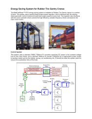
Energy Savings using a TMEIC Variable Frequency <strong>Drive</strong> Fan System<br />
Variable flow can be provided by varying fan RPM to precisely match process operating conditions. The variable frequency<br />
drive provides variable fan speed which varies <strong>the</strong> air flow according to <strong>the</strong> system resistance.<br />
Main Power<br />
14.4 kV or<br />
below<br />
Dura-Bilt5i MV VFD<br />
(<strong>for</strong> example 1,000 hp)<br />
Variable<br />
Frequency<br />
Three-phase<br />
Induction Motor<br />
Induced Draft Fan<br />
Induced Air Flow<br />
from Kiln<br />
Output Flow<br />
The first chart shows how different fan speeds are<br />
used to select <strong>the</strong> proper operating points A through<br />
E on <strong>the</strong> system resistance curve. Depending upon<br />
<strong>the</strong> size of <strong>the</strong> cement kiln, <strong>the</strong> required ID fan output<br />
power can vary from a few hundred hp to several<br />
thousand hp. The second chart shows a system using<br />
mechanical dampers to achieve flow control. Pairs<br />
of flow and pressure operating points correspond to<br />
points A through E.<br />
Power level percentages shown are total input power<br />
including all motor, trans<strong>for</strong>mer, fan, and system<br />
losses as percentages of required fan output power.<br />
The energy deltas (vertical lines) allow calculation of<br />
energy savings and drive cost justification. A table<br />
of expected annual operating times and power level<br />
differences is shown below. Energy cost factors <strong>for</strong><br />
<strong>the</strong> site are applied and <strong>the</strong> annual savings calculated.<br />
Static Pressure Rise<br />
Operating Point A<br />
140<br />
Pressure Drop and Power<br />
System<br />
Resistance<br />
Speed A<br />
Speed B<br />
Speed C<br />
Speed D<br />
Speed E<br />
Operating Point B<br />
Operating Point C<br />
Operating Point D<br />
Operating Point E<br />
Percent Power<br />
120<br />
100<br />
80<br />
60<br />
40<br />
20<br />
Outlet<br />
Damper<br />
Inlet<br />
Vanes<br />
<strong>Drive</strong><br />
Power<br />
Fan<br />
Output<br />
Flow<br />
Power<br />
Flow<br />
0<br />
20 40 60 80 100<br />
% Flow<br />
Ref<br />
Point<br />
Required<br />
Flow %<br />
% Power Using<br />
Outlet Damper<br />
Control<br />
% Power Using<br />
Adjustable Speed<br />
<strong>Drive</strong><br />
Delta % Power<br />
Saved<br />
% Time on<br />
Annual Basis<br />
% Saved on<br />
Annual<br />
Basis<br />
A 90 120 91 29 15 4.35<br />
B 80 117 66 51 25 12.75<br />
C 70 111 46 65 25 16.25<br />
D 60 103 34 69 20 13.8<br />
E 50 96 23 73 15 10.95<br />
Total Annual % Energy Consumption Savings 58.1<br />
Savings. Based on <strong>the</strong> annualized percent<br />
savings in <strong>the</strong> table, an ID fan system with 1,000<br />
hp output, operating <strong>for</strong> 8,000 of 8,760 hours per<br />
year, at an energy cost of $0.035 per kWh, saves:<br />
1000 x 0.746 x 58.1% x $.035 x 8000 = $121,359<br />
If installed added costs of drive equipment are<br />
$150,000, <strong>the</strong> payback period will be only 15<br />
months. A good return on investment!<br />
© 2011 TMEIC Corporation. All Rights Reserved. Page 5 of 28