Download the TMdrive-10 SPR Product Application Guide - Tmeic.com
Download the TMdrive-10 SPR Product Application Guide - Tmeic.com
Download the TMdrive-10 SPR Product Application Guide - Tmeic.com

You also want an ePaper? Increase the reach of your titles
YUMPU automatically turns print PDFs into web optimized ePapers that Google loves.
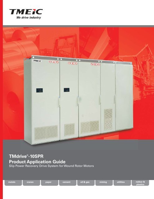
<strong>TMdrive</strong> ® -<strong>10</strong><strong>SPR</strong><br />
<strong>Product</strong> <strong>Application</strong> <strong>Guide</strong><br />
Slip Power Recovery Drive System for Wound Rotor Motors<br />
metals cranes<br />
paper cement oil & gas mining utilities<br />
rubber &<br />
plastics
With <strong>the</strong> <strong>TMdrive</strong>-<strong>10</strong><strong>SPR</strong>,<br />
wound rotor motor drives<br />
have entered <strong>the</strong> 21st century,<br />
offering:<br />
• PWM converters<br />
Utility<br />
Supply<br />
Recovered power<br />
Three-phase<br />
Motor Stator<br />
Utility Interface<br />
Transformer<br />
PWM Rotor<br />
Inverter<br />
Power Flow at<br />
normal speeds<br />
PWM Source<br />
Converter<br />
• High power factor operation<br />
<strong>TMdrive</strong>-<strong>10</strong><strong>SPR</strong><br />
• High reliability<br />
• Low cost of ownership<br />
Brushes and<br />
Slip Rings<br />
Wound Rotor<br />
Induction Motor<br />
Rheostat<br />
Starting duty rated<br />
Features<br />
Benefits<br />
Based on Standard Drive<br />
Standard TMEIC low voltage drive hardware is<br />
applied for use as a wound rotor motor drive.<br />
Reliable Drive Hardware & Available Spare Parts<br />
The <strong>TMdrive</strong>-<strong>10</strong> drive hardware is in production.<br />
No modifications to <strong>the</strong> hardware are required for<br />
use as a slip power recovery drive.<br />
High Power Factor, Low Harmonic Utility<br />
Interface<br />
Source converter feeding power back into<br />
utility operates at unity power factor.<br />
Reduction of Current to Motor and Reduced<br />
Harmonics<br />
Higher PF operation means reduced reactive power<br />
demands and better voltage stability. Reduced<br />
harmonics result in no filtering on utility supply.<br />
Low Harmonic Currents in Rotor Circuit<br />
PWM converter connected to rotor provides<br />
sinusoidal current to rotor<br />
Negligible Rotor Heating and Smooth Motor<br />
Torque<br />
Sinusoidal current in rotor circuit results in<br />
negligible rotor heating and torque pulsations.<br />
Latest Drive Control Technology<br />
Based on current production drive control<br />
hardware and firmware.<br />
Intelligent Drive Control<br />
Using modern drive control provides <strong>the</strong> latest in<br />
drive <strong>com</strong>munications, operating accuracy, and<br />
diagnostics.<br />
Heat Pipe Cooling Technology<br />
The cabinet-based IGBT power bridges use<br />
heat pipe cooling technology.<br />
Precise control of wound rotor motor while<br />
not wasting energy<br />
Reduces Footprint and Lowers Audible Noise<br />
This cooling system reduces <strong>the</strong> space required for<br />
effective IGBT cooling. It also lowers <strong>the</strong> speed of<br />
<strong>the</strong> cooling air, <strong>the</strong>reby reducing audible noise.<br />
• Drive controls motor torque (rotor current)<br />
directly; motor does not have to increase slip<br />
(slow down) to increase torque<br />
• Slip power is recovered and fed back to power<br />
system when <strong>the</strong> motor is operating below<br />
synchronous speed<br />
Page 2 of 12<br />
© 2011 TMEIC Corporation. All Rights Reserved.
Slip Power Recovery<br />
Wound rotor induction motors have been popular in some<br />
industries, particularly cement, for decades. Until about 1985, a<br />
wound rotor induction motor (WRIM) was <strong>the</strong> only large ac motor<br />
that allowed controlled starting characteristics and adjustable<br />
speed capability.<br />
A WRIM is a machine with a 3-phase wound stator that is<br />
usually connected directly to <strong>the</strong> power system. The rotor<br />
also has a 3-phase winding, usually connected in a wye<br />
(or star) circuit. The three terminals of <strong>the</strong> rotor winding<br />
are connected to separate slip rings, which are normally<br />
connected to a liquid rheostat or resistor bank. Changing rotor<br />
resistance changes <strong>the</strong> motor speed. In <strong>the</strong> past <strong>the</strong> power in<br />
<strong>the</strong> resistor was lost as heat. The slip power recovery drive,<br />
<strong>TMdrive</strong>-<strong>10</strong><strong>SPR</strong>, is used to vary <strong>the</strong> motor speed by varying<br />
<strong>the</strong> power taken off <strong>the</strong> rotor and returned to <strong>the</strong> utility supply.<br />
SAG Mill for grinding ore<br />
Slip Rings<br />
Wound Rotor<br />
Rotor from WRIM showing Slip Rings<br />
Large pumps in a Water Treatment Plant<br />
Wound rotor motors continue to be applied in some industries,<br />
especially in ore processing, cement, and water/wastewater.<br />
Speed control of wound rotor motors has traditionally employed<br />
slip power recovery (<strong>SPR</strong>) drives for cost and energy efficiency<br />
reasons. Older implementations of <strong>SPR</strong> technology saved energy,<br />
but had disadvantages of low power factor operation and torque<br />
pulsations.<br />
The use of state-of-<strong>the</strong>-art low voltage PWM converters<br />
eliminates <strong>the</strong>se disadvantages while retaining all <strong>the</strong> energy<br />
savings. This new implementation builds on <strong>the</strong> standard line<br />
of TMEIC low voltage induction motor drives used in process<br />
industries such as metal processing and paper machines.<br />
Therefore <strong>the</strong> hardware is very reliable and familiar. The<br />
TM-<strong>10</strong><strong>SPR</strong> is appropriate for new motors or existing motors.<br />
Cement Plant<br />
© 2011 TMEIC Corporation. All Rights Reserved. Page 3 of 12
<strong>Application</strong> 1. Slip Power Recovery Drive System for a water treatment plant<br />
Eight large vertical pumps handling wastewater at this Canadian water treatment plant were driven by 4 kV wound rotor<br />
induction motors. Four of <strong>the</strong> motors were 3050 HP, and four were 5158 HP, all controlled by 1975 vintage variable speed<br />
controls using diode rectifiers and thyristor converters. Oil-filled rheostats on each motor provided start and speed<br />
control.<br />
The Customer Need<br />
The oil-filled rheostats posed a fire hazard, and parts and service for <strong>the</strong> old thyristor controls were hard to obtain. The<br />
municipality decided to purchase new controls for <strong>the</strong> original motors and pumps, and narrowed <strong>the</strong> choice down to two<br />
systems, a medium voltage drive supplying <strong>the</strong> WRIM, or a low voltage slip power recovery drive (<strong>SPR</strong>) connected to <strong>the</strong><br />
WRIM rotor slip rings, (example on page 5). The new controls were required to fit in <strong>the</strong> foot print of <strong>the</strong> old drives.<br />
The Best Solution: <strong>TMdrive</strong>-<strong>10</strong><strong>SPR</strong> for each pump<br />
• The <strong>SPR</strong> drive carrying slip power is much smaller and less expensive than<br />
an MV drive carrying all <strong>the</strong> motor power at full speed (4 kV voltage)<br />
• The <strong>SPR</strong> drive has a smaller footprint than a large stator supply drive<br />
• Inherent fault tolerance - a failure of <strong>the</strong> <strong>SPR</strong> drive will not prevent <strong>the</strong><br />
motor’s operation<br />
• The <strong>SPR</strong> drive can work with any stator-rated voltage, but an MV drive can<br />
be difficult to match with <strong>the</strong> motor.<br />
• The <strong>SPR</strong> drive can offer higher overall system efficiency, thus saving energy,<br />
and can perform additional VAR <strong>com</strong>pensation.<br />
• Running at or above synchronous speed is possible if <strong>the</strong> motors are rated<br />
for <strong>the</strong> higher speeds.<br />
• The new drive footprint featured a back-to-back configuration to line up<br />
with <strong>the</strong> existing cable and conduits buried in <strong>the</strong> concrete floor.<br />
• The HMI has one button to switch from English to French displays<br />
• CSA approval required a special inspection for this non-standard panel<br />
<strong>Application</strong> 2. Slip Power Recovery Drive System for a grinding mill<br />
One of eight pumps<br />
This new $250 M ore processing facility in Papua New Guinea can process up to 4.7 million tons of ore per year, resulting<br />
in about 275,000 ounces of annual gold production. This variable speed drive application is a dual-pinion SAG mill driven<br />
by two 5,000 kW wound rotor induction motors. Two <strong>TMdrive</strong>-<strong>10</strong><strong>SPR</strong>s control motor speed by recovering rotor current<br />
and returning <strong>the</strong> power to <strong>the</strong> utility supply.<br />
The Customer Need<br />
Reliability, power dependency and logistics were a challenge for this project. Limited access to <strong>the</strong> mine’s extremely<br />
remote location required power recovery and stellar reliability in its operations.<br />
The Best Solution: <strong>TMdrive</strong>-<strong>10</strong><strong>SPR</strong> for each mill motor<br />
• The <strong>TMdrive</strong>-<strong>10</strong><strong>SPR</strong> has high reliability and a good track record.<br />
• Configured in a twin motor arrangement, <strong>the</strong> motors share load<br />
in <strong>the</strong> tandem mill. The first motor provides speed control, <strong>the</strong><br />
second motor provides torque control<br />
• Continuously recovers an estimated 770 kW<br />
• Inherent fault tolerance - a failure of <strong>the</strong> <strong>SPR</strong> drive will not<br />
prevent <strong>the</strong> motor’s operation<br />
• The <strong>SPR</strong> drive offers high overall system efficiency, thus saving<br />
energy, and can perform additional VAR <strong>com</strong>pensation<br />
SAG Mill and Motor<br />
Page 4 of 12<br />
© 2011 TMEIC Corporation. All Rights Reserved.
<strong>Application</strong> 3. Energy Savings using Slip Power Recovery Drive System<br />
The example below <strong>com</strong>pares <strong>the</strong> case of an induction motor driven by a large standard drive, with <strong>the</strong> case of a WRIM<br />
controlled by a small <strong>SPR</strong> drive, and calculates <strong>the</strong> energy savings. In <strong>the</strong> larger standard drive system, all <strong>the</strong> motor<br />
power passes through <strong>the</strong> drive. With <strong>the</strong> <strong>SPR</strong> drive, only a fraction of <strong>the</strong> motor power passes through <strong>the</strong> drive.<br />
For a rated pump load of 5,000 hp, running at 90% speed, <strong>the</strong> power saving using <strong>the</strong> <strong>SPR</strong> drive is 88 kW. With an electrical<br />
cost of 7¢/kWh, <strong>the</strong> annual savings amount to $53,960. At lower speeds <strong>the</strong> savings are even higher.<br />
Compared to a WRIM using only a rheostat to control speed, where all of <strong>the</strong> slip power is wasted as heat, <strong>the</strong> <strong>SPR</strong> drive<br />
saves $176,000 annually.<br />
P1<br />
Utility supply<br />
Power flow<br />
P5<br />
Slip power recovery flow after<br />
transformer<br />
Induction<br />
Induction<br />
Motor<br />
Motor<br />
P2<br />
MV Variable Speed Drive<br />
(larger capacity)<br />
Power flow to<br />
motor stator<br />
P1<br />
Utility<br />
supply<br />
power flow<br />
P2 Power flow to<br />
motor stator<br />
P4 Power<br />
flow to <strong>SPR</strong><br />
Transformer<br />
<strong>TMdrive</strong>-<strong>10</strong><strong>SPR</strong><br />
(smaller drive)<br />
Pump<br />
load<br />
P3<br />
Motor shaft<br />
power flow<br />
P2 = P1 - Drive losses<br />
P3 = P2 - Motor losses<br />
Standard Drive & Induction Motor<br />
Wound Rotor<br />
Induction Motor<br />
P3<br />
Pump shaft<br />
power flow<br />
Pump<br />
load<br />
P2 = P1 + P5<br />
P4 = P2 - P3 - Motor Losses<br />
P5 = P4 - Drive & Tfmr Losses<br />
Slip Power Recovery Drive and Wound Rotor Motor<br />
Operating Conditions<br />
Pump Load at Full Speed, shaft kW<br />
Power<br />
Flow<br />
–<br />
Standard Drive &<br />
Induction Motor<br />
3730 kW (5,000 hp)<br />
Slip Power Recovery Drive & Wound<br />
Rotor Motor<br />
3730 kW (5,000 hp)<br />
Pump load at 90% speed, shaft kW<br />
P3<br />
2720 kW<br />
2720 kW<br />
Utility supply power flow<br />
P1<br />
2980 kW<br />
2892 kW<br />
Power flow to motor stator<br />
P2<br />
2863 kW<br />
3180 kW<br />
Power flow to Slip power recovery drive<br />
P4<br />
0<br />
300 kW<br />
Slip power recovery after transformer<br />
P5<br />
0<br />
288 kW<br />
Difference in utility power flows<br />
–<br />
–<br />
88 kW<br />
P1 (Induction motor ) - P1 (WRIM)<br />
<strong>SPR</strong> system savings with 7¢/kWH electrical<br />
power<br />
–<br />
–<br />
$53,960 per year<br />
© 2011 TMEIC Corporation. All Rights Reserved. Page 5 of 12
A Look Inside<br />
Two-Level Phase Leg<br />
Assembly<br />
The cabinet style inverters have<br />
modular two-level phase leg<br />
assemblies. Each phase leg<br />
includes:<br />
• IGBTs with flyback diodes<br />
• Heat pipe assembly<br />
• IGBT gate driver circuit board<br />
Control Functions<br />
Each inverter and regenerative<br />
converter shares a <strong>com</strong>mon set of<br />
control boards. The primary control<br />
board performs several functions:<br />
• Speed and torque regulation<br />
• Sequencing<br />
• I/O mapping<br />
• Diagnostic data ga<strong>the</strong>ring<br />
A mounting bracket is provided for<br />
an optional LAN interface board.<br />
In<strong>com</strong>ing Power<br />
The converter in each lineup is fed<br />
3-phase ac power. In addition,<br />
3-phase ac control power is fed to<br />
each converter and inverter in <strong>the</strong><br />
lineup. A control power disconnect<br />
is provided in each cabinet.<br />
Page 6 of 12<br />
© 2011 TMEIC Corporation. All Rights Reserved.
Heat Pipe Cooling<br />
Technology<br />
The cabinet style inverters and<br />
regenerative converters use heat<br />
pipes to cool <strong>the</strong> IBGT power<br />
switches and capacitors. This<br />
technology reduces <strong>the</strong> footprint<br />
of <strong>the</strong> power bridge as well<br />
as <strong>the</strong> airflow requirements,<br />
saving valuable floor space and<br />
dramatically reducing <strong>the</strong> audible<br />
noise.<br />
I/O Board<br />
All <strong>TMdrive</strong>-<strong>10</strong> products share a<br />
<strong>com</strong>mon I/O board. The I/O board<br />
supports an encoder, 24 V dc I/O,<br />
115 V ac inputs, and analog I/O,<br />
standard. In addition, a resolver<br />
interface option can be provided.<br />
All I/O are terminated to a two-piece<br />
modular terminal block for ease of<br />
maintenance.<br />
DC Bus<br />
The converter in each lineup<br />
generates dc power for each of <strong>the</strong><br />
inverters. The inverters <strong>the</strong>n create<br />
variable frequency ac power to<br />
control <strong>the</strong> induction motors. This<br />
dc power for <strong>the</strong> lineup is conveyed<br />
on a solid copper bus near <strong>the</strong><br />
bottom of <strong>the</strong> cabinets. Tin-plated<br />
bus may be used.<br />
© 2011 TMEIC Corporation. All Rights Reserved. Page 7 of 12
Operator Interface<br />
High Function Display<br />
• LCD backlight gives great visibility and long life<br />
• Bar graphs, icons, menus, and digital values <strong>com</strong>bine to<br />
provide concise status information, often eliminating <strong>the</strong><br />
need for traditional analog meters<br />
Easy-to-understand navigation buttons<br />
allow quick access to information<br />
without resorting to a PC-based tool<br />
RJ-45 E<strong>the</strong>rnet port<br />
is used for <strong>the</strong> local<br />
toolbox connection<br />
Instrumentation Interface<br />
• Two analog outputs are dedicated to motor<br />
current feedback<br />
• Five analog outputs can be mapped to<br />
variables for external data logging and analysis<br />
Interlock button<br />
disables <strong>the</strong> drive<br />
Switch to local<br />
mode and operate<br />
<strong>the</strong> equipment right<br />
from <strong>the</strong> keypad<br />
How to Apply <strong>SPR</strong><br />
<strong>Application</strong> of <strong>the</strong> <strong>TMdrive</strong>-<strong>10</strong><strong>SPR</strong> starts with <strong>the</strong> motor<br />
speed range, <strong>the</strong> rated rotor current, <strong>the</strong> rated rotor<br />
voltage (at standstill), and any overload requirements.<br />
The speed range and <strong>the</strong> rotor voltage determine <strong>the</strong><br />
maximum operating voltage of <strong>the</strong> <strong>TMdrive</strong>-<strong>10</strong><strong>SPR</strong>. The<br />
rotor voltage is at rated value at standstill and reaches zero<br />
at synchronous speed. Therefore, <strong>the</strong> voltage at minimum<br />
controlled speed is:<br />
Vc = Vrated * (<strong>10</strong>0-Nmin), where<br />
Vrated = rated rotor voltage, and<br />
min = minimum controlled speed in percent<br />
The rated rotor current and overloads determine <strong>the</strong><br />
required inverter current capacity. The inverter continuous<br />
current rating must be equal to <strong>the</strong> rated rotor current and<br />
must be rated for any overloads.<br />
The rating of <strong>the</strong> converter is determined from <strong>the</strong> speed<br />
range and <strong>the</strong> power to be recovered from <strong>the</strong> rotor.<br />
For a variable torque load (pump or fan), <strong>the</strong> maximum<br />
regenerated power is 15% of <strong>the</strong> motor rating. By contrast,<br />
<strong>the</strong> power regenerated from a motor powering a constant<br />
torque load is equal to motor rating times <strong>the</strong> speed range<br />
in percent.<br />
As an example, consider a 3000 HP motor with a 4 kV stator,<br />
a rotor voltage of 1200V, rotor current of 1150 A, speed<br />
range of 70 – 96%, and no overloads exceeding 150% for<br />
60 sec, driving a fan. The maximum rotor voltage is 360 V,<br />
so a 460 V inverter is applicable. The inverter size is a <strong>10</strong>00<br />
frame with a current rating of 1506 amps. The regenerated<br />
power is 335 kW, so <strong>the</strong> line converter is a 700 frame. O<strong>the</strong>r<br />
<strong>com</strong>ponents such as <strong>the</strong> utility interface transformer and<br />
rotor contactors must also ac<strong>com</strong>modate <strong>the</strong>se ratings.<br />
Page 8 of 12<br />
© 2011 TMEIC Corporation. All Rights Reserved.
Specifications<br />
Inverter Specifications for models without DC disconnects<br />
Frame<br />
400<br />
500<br />
700<br />
900<br />
<strong>10</strong>00<br />
1400<br />
1800<br />
Weight<br />
kg (lbs)<br />
395<br />
(869)<br />
Full Load Loss<br />
(kW)<br />
460 V ac 575 / 690 V ac<br />
Rotor Current<br />
A ac<br />
Allowable<br />
Overload %<br />
Rotor Current<br />
A ac<br />
528 <strong>10</strong>0 - 150 352<br />
6.3 469 175 302<br />
411 200 264<br />
753 <strong>10</strong>0 - 150 486<br />
400 7.5 669 175 417<br />
(880) 586 200 365<br />
960 <strong>10</strong>0 -150 586<br />
405 9.3 861 175 502<br />
(892) 753 200 440<br />
1130 <strong>10</strong>0 - 150 720<br />
4<strong>10</strong> 13.5 969 175 617<br />
(902) 848 200 540<br />
1506 <strong>10</strong>0 - 150 972<br />
800 14.9 1339 175 883<br />
(1760) 1171 200 729<br />
1920 <strong>10</strong>0 - 150 1172<br />
8<strong>10</strong> 18.6 1721 175 <strong>10</strong>05<br />
(1782) 1506 200 879<br />
2260 <strong>10</strong>0 - 150 1440<br />
820 27 1937 175 1234<br />
(1804) 1695 200 <strong>10</strong>80<br />
Source Converter Specifications<br />
Frame<br />
300<br />
700<br />
900<br />
1400<br />
1800<br />
Weight<br />
kg (lbs)<br />
Loss<br />
kW<br />
460 V ac 575/690 V ac<br />
Power<br />
kW<br />
Current<br />
A ac<br />
Allowable<br />
Overload<br />
Power at<br />
575 V ac<br />
Power at<br />
690 V ac<br />
Current<br />
A ac<br />
475 3.7 236 308 150 196 235 205<br />
(<strong>10</strong>45) 290 200 180<br />
680 8.5 533 697 150 445 534 465<br />
(1496) 697 200 407<br />
795 11 709 926 150 590 709 617<br />
(1749) 895 200 540<br />
1330 17 <strong>10</strong>67 1394 150 890 <strong>10</strong>67 929<br />
(2926) 1394 200 813<br />
1560 27 1417 1852 150 1180 1416 1235<br />
(3432) 1790 200 <strong>10</strong>80<br />
© 2011 TMEIC Corporation. All Rights Reserved. Page 9 of 12
Inverter Specifications<br />
Inverter Power Output<br />
Motor Control<br />
Output Voltage<br />
Output Frequency<br />
Output Chopping<br />
Frequency<br />
Inverter Type Modulation<br />
Power Semiconductor<br />
Technology<br />
Inverter Notes<br />
0-460 V, 0-690 V<br />
0 - 200 Hz<br />
0 - 400 Hz Optional<br />
Continuous operation below 0.4 Hz<br />
requires derate<br />
1.5 kHz for 200-1800 frames<br />
2 kHz for 4-125 frames<br />
Up to 6 kHz available with derating<br />
Two-level voltage converter Pulse<br />
Width Modulation (PWM)<br />
Insulated Gate Bipolar Transistor<br />
(IGBT)<br />
With Speed Sensor (Resolver or Encoder)<br />
Speed regulator accuracy: +/- 0.01%<br />
Maximum speed response: 60 rad/sec<br />
Torque linearity: +/-3% with temperature sensor<br />
+/- <strong>10</strong>% without temperature sensor<br />
Maximum Torque current response: <strong>10</strong>00 rad/sec<br />
Torque range: 0-400% of rated motor torque<br />
Maximum flux control range: 20%-<strong>10</strong>0%<br />
Without Speed sensor<br />
Speed regulator accuracy:<br />
+/- 0.1% with temperature sensor<br />
+/- 0.2% without temperature sensor<br />
(Using 1% slip motor at rated flux)<br />
Maximum speed regulator response: 20/rad/sec<br />
Minimum continuous speed: 3%<br />
Torque linearity: +/- <strong>10</strong>%<br />
Maximum Torque current response: <strong>10</strong>00 fad/sec<br />
Torque range: 0-150% of rated motor torque<br />
Maximum flux control range: 75%-<strong>10</strong>0%<br />
1. All inverter cabinets are 605 mm (24 in.) in depth. All equipment<br />
requires a steel support of at least 50 mm (2 in) under <strong>the</strong> panel (not<br />
included in <strong>the</strong>se dimensions). All shipping splits are 2.4 m maximum.<br />
Reserve an additional 115 mm (5 in.) in height for equipment requiring<br />
a debris hood (UL).<br />
2. A minimum of 500 mm (20 in) should be allocated above cabinet for<br />
fan maintenance. No back access is required. Reserve 800 mm (32 in)<br />
front clearance for maintenance.<br />
3. Motor power ratings based assume 150% overloads, motor efficiency<br />
of 95%, motor power factor of 0.85, ambient temperature 0-40° C (32-<br />
<strong>10</strong>4° F), an altitude below 2000 m (3280 ft) above sea level. Use actual<br />
motor data for final inverter selection.<br />
4. The specified current ratings are continuous to which <strong>the</strong> referenced<br />
overload can be applied for a maximum of 60 seconds. Refer to<br />
application example on <strong>the</strong> previous page.<br />
5. Inverters support bottom cable entry. Top cable entry is supported<br />
with one 600 mm (24 in) auxiliary cabinet between every two inverter<br />
cabinets.<br />
6. Each of <strong>the</strong> inverters requires 2-phase control power.<br />
7. For high-performance torque regulation, a temperature sensor is<br />
mounted in <strong>the</strong> motor.<br />
8. Speed and current regulator responses are <strong>com</strong>puter per <strong>the</strong> adjacent<br />
Environmental (Inverters and Converters)<br />
figure in radians/s. Speed regulator responses<br />
shown are maximum available. Actual response<br />
will be limited by drive train mechanical conditions.<br />
Accuracy and linearity specifications shown are as<br />
measured under controlled conditions in our lab and<br />
while typical may not be achievable in all systems.<br />
9. Air is pulled in through <strong>the</strong> front and out <strong>the</strong><br />
top for all Cabinets.<br />
<strong>10</strong>. The dc bus for <strong>the</strong> lineup has a maximum<br />
current capacity of 2000 amps.<br />
11. High temperature current derating: all frames<br />
-2.5% per °C below 0 °C above 40° C.<br />
12. Inverter doors are electrically interlocked with controls to inhibit<br />
gating when <strong>the</strong> doors are open.<br />
13. Low temperature current derating: frames 200 to 1800 -1.75% per °C<br />
except frame 400 which is -2.5% per °C below 0 °C all o<strong>the</strong>r frames<br />
no derating.<br />
14. The ratings shown in green in <strong>the</strong> inverter table for motor currents<br />
and <strong>the</strong> associated overload percent indicate <strong>the</strong> maximum peak<br />
current that inverter frame can produce.<br />
Mechanical (Inverters and Converters)<br />
Operating Temperature<br />
Storage Temperature<br />
Humidity<br />
Altitude<br />
0 to 40°C (32 to <strong>10</strong>4°F) at rated load<br />
-20 to 50°C (-4 to 122°F) with derating<br />
-25 to 55°C (-13 to 131°F)<br />
5 to 95% relative humidity<br />
Non-condensing<br />
0 to 5000 m (16,400 ft) above sea level<br />
Derate current ratings: 1% per 200m<br />
(656ft)<br />
altitude above <strong>10</strong>00 m (3280 ft)<br />
Derate voltage 2.25% per 200 m (656 ft)<br />
for 460 V inverters above 4000 m (13120<br />
ft)<br />
for 575 V inverters above 3000 m (9840 ft)<br />
for 690 V inverters above 2000 m (6560 ft)<br />
Vibration <strong>10</strong>-50 Hz, 41,000 hours<br />
Applicable IEC, JIS, JEM, UL, CSA and<br />
NEMA standards (entire lineup extra cost<br />
option)<br />
Page <strong>10</strong> of 12<br />
© 2011 TMEIC Corporation. All Rights Reserved.
Control Functions<br />
Control Functions<br />
LAN Interface Options<br />
Instrumentation Interface<br />
ISBus<br />
• Supports both run-time control (<strong>10</strong> words in and <strong>10</strong> words out) and<br />
Toolbox configuration/monitoring using <strong>the</strong> Innovation Series controller<br />
as a gateway between <strong>the</strong> ISBus and E<strong>the</strong>rnet<br />
• RS-485 or optional fiber-optic bus in a synchronous ring configuration<br />
• 5 Mbps master/follower (drive is <strong>the</strong> follower) protocol using copper<br />
or fiber; bus scan time based on <strong>the</strong> number of nodes:<br />
Quantity of Nodes<br />
Bus Scan Time<br />
2-4 1 ms<br />
17-32 8 ms<br />
Configuration<br />
Meter Outputs<br />
Digital Inputs<br />
Digital Outputs<br />
Analog Inputs<br />
Analog Outputs<br />
(Optional)<br />
Speed Feedback<br />
Resolver Input<br />
Speed Feedback<br />
Encoder Input<br />
Speed Tach<br />
Follower Output<br />
Motor<br />
Temperature<br />
Feedback<br />
I/O Interface<br />
• RJ-45 E<strong>the</strong>rnet interface<br />
• <strong>10</strong> Mbps maximum<br />
• Toolbox option of ISBus to<br />
E<strong>the</strong>rnet using Innovation<br />
Series controller as gateway<br />
• Motor current A and B, ±<strong>10</strong><br />
V<br />
• Quantity 5 configurable, ±<strong>10</strong><br />
V, 8-bit resolution<br />
• Opto-coupled 20 mA<br />
• Quantity 6 configurable mapping<br />
• Opto-coupled <strong>10</strong> mA<br />
• Quantity 1 configurable mapping<br />
• Quantity 1 dedicated mapping<br />
• Open collector 70 mA<br />
• Quantity 6 user defined<br />
• Quantity 2 ± <strong>10</strong> V or 4-20 mA<br />
- Differential 8 Ω input impedance<br />
- 12 bit resolution<br />
• Optional Quantity 2 ± <strong>10</strong> V<br />
- 12 bit resolution (Optional for<br />
Inverters only)<br />
• Quantity 3 ± <strong>10</strong> V, <strong>10</strong> mA max<br />
• User defined<br />
• 8-bit resolution<br />
• Excitation frequency of 1 or 4<br />
kHz<br />
• Source for resolvers is<br />
Tamagawa:<br />
www.tamagawa-seiki.co.jp<br />
• A quad B with marker<br />
• Maximum frequency of <strong>10</strong>0 kHz<br />
• Differential 5 or 15 V dc<br />
• 5 of 15 V dc at 200 mA supply<br />
• Maximum frequency of <strong>10</strong> kHz<br />
• External 15-24 V dc at <strong>10</strong>0 mA<br />
max<br />
• High-resolution torque motor<br />
temperature feedback<br />
• 1 kΩ positive temperature<br />
coefficient RTD or o<strong>the</strong>r<br />
sensor using optional signal<br />
conditioning module<br />
TOSLINE-S20<br />
• Supports both run-time control (6 words in and <strong>10</strong> words out) from<br />
an Innovation Series controller or v series controller<br />
• Drives can directly exchange data between <strong>the</strong>mselves (4 words)<br />
• Fiber-optic bus in a star configuration<br />
• 2Mbps peer-to-peer protocol; bus scan time based on <strong>the</strong> number of<br />
nodes:<br />
Quantity of Nodes<br />
Bus Scan Time<br />
2-3 1 ms<br />
9-64 25 ms<br />
Modbus<br />
• Supports run-time control (fixed <strong>10</strong> words in/out) from a Modbus-<br />
RTU controller<br />
• RS-485 copper bus<br />
• 1.2 kbps to 57.6 kbps master/follower protocol; update rates up to 20<br />
ms/node possible at <strong>the</strong> highest baud rate<br />
• Number of nodes: 127 max per LAN<br />
Profibus-DP<br />
• Supports run-time control (6 words in and <strong>10</strong> out) from a Profibus-DP<br />
master controller<br />
• Copper bus in a daisy-chain configuration<br />
• 9.6 kbps to 12 Mbps master/follower protocol; bus scan time based<br />
on <strong>the</strong> number of nodes<br />
DeviceNet<br />
• Supports run-time control (4 words in and <strong>10</strong> words out) from a<br />
DeviceNet master controller<br />
• Copper bus in a daisy-chain configuration<br />
• 125 kbps to 500 kbps master/follower protocol; bus scan time based<br />
on <strong>the</strong> number of nodes<br />
E<strong>the</strong>rnet Global Data (EGD)<br />
• Supports run-time control (<strong>10</strong> words in/out)<br />
• RJ-45 E<strong>the</strong>rnet interface<br />
• Update rates up to 20 ms using standard <strong>10</strong> Mbps hardware or rates<br />
up to 2 ms with optional <strong>10</strong>0 Mbps card<br />
• Drives can exchange data directly<br />
• Supports peer-to-peer operation (no master needed)<br />
• No limit to maximum number of nodes<br />
Note: 1 word = 16 bits<br />
© 2011 TMEIC Corporation. All Rights Reserved. Page 11 of 12
TMEIC AC Drives Offer Complete Coverage<br />
Global Office Locations:<br />
TMEIC Corporation<br />
Office: 1325 Electric Road, Suite 200<br />
Roanoke, VA 24018<br />
Mailing: 2060 Cook Drive<br />
Salem, VA, United States, 24153<br />
Tel: +1-540-283-2000<br />
Web: www.tmeic.<strong>com</strong><br />
Email: info@tmeic.<strong>com</strong><br />
TOSHIBA MITSUBISHI-ELECTRIC INDUSTRIAL SYSTEMS<br />
CORPORATION<br />
Mita 43 MT Bldg.<br />
13-16 Mita 3 chome, Minato-ku, Tokyo<br />
<strong>10</strong>8-0073, Japan<br />
Tel: +81-3-5444-3828<br />
Web: www.tmeic.co.jp<br />
TMEIC Europe Limited<br />
Albany House 71-79 Station Road<br />
West Drayton, Middlesex, United Kingdom<br />
UB7 7LT<br />
Tel: +44-870-950-7220<br />
Web: www.tmeic.<strong>com</strong><br />
Email: info@tmeic.eu<br />
TMEIC Industrial Systems India Private Limited<br />
Unit #03-04, Third Floor<br />
Block 2, Cyber Pearl, HITEC City, Madhapur<br />
Hyderabad, 500081, Andhra Pradesh, India<br />
Tel: +91-40-4434-0000<br />
Web: www.tmeic.in<br />
Email: inquiry_india@tmeic.<strong>com</strong><br />
TOSHIBA MITSUBISHI-ELECTRIC INDUSTRIAL SYSTEMS<br />
(Beijing) CORPORATION<br />
21/F., Building B., In.do Mansion<br />
48 Zhichunlu A, Haidian District,<br />
Beijing <strong>10</strong>0098, PRC<br />
Tel: +86-<strong>10</strong>-5873-2277<br />
Web: www.tmeic-cn.<strong>com</strong><br />
<strong>TMdrive</strong> is a registered trademark of Toshiba Mitsubishi-Electric Industrial Systems Corporation.<br />
TMEIC is a registered trademark of Toshiba Mitsubishi-Electric Industrial Systems Corporation.<br />
TM is a registered trademark of TMEIC Corporation.<br />
All o<strong>the</strong>r products mentioned are registered trademarks and/or trademarks of <strong>the</strong>ir respective<br />
<strong>com</strong>panies.<br />
All specifications in this document are subject to change without notice. The above brochure is<br />
provided free of charge and without obligation to <strong>the</strong> reader or to TMEIC Corporation. TMEIC<br />
Corporation does not accept, nor imply, <strong>the</strong> acceptance of any liability with regard to <strong>the</strong> use<br />
of <strong>the</strong> information provided. TMEIC Corporation provides <strong>the</strong> information included herein as is<br />
and without warranty of any kind, express or implied, including, but not limited to, any implied<br />
statutory warranty of merchantability or fitness for particular purposes. The information is<br />
provided solely as a general reference to <strong>the</strong> potential benefits that may be attributable to<br />
<strong>the</strong> technology discussed. Individual results may vary. Independent analysis and testing of<br />
each application is required to determine <strong>the</strong> results and benefits to be achieved from <strong>the</strong><br />
technology discussed.<br />
© 2011 TMEIC Corporation. All Rights Reserved.<br />
P-1131