TMdrive-MVG Series Catalog - Tmeic.com
TMdrive-MVG Series Catalog - Tmeic.com
TMdrive-MVG Series Catalog - Tmeic.com

Create successful ePaper yourself
Turn your PDF publications into a flip-book with our unique Google optimized e-Paper software.
Energy Savings Payback Calculations<br />
Appendix. Energy Savings Payback Calculations<br />
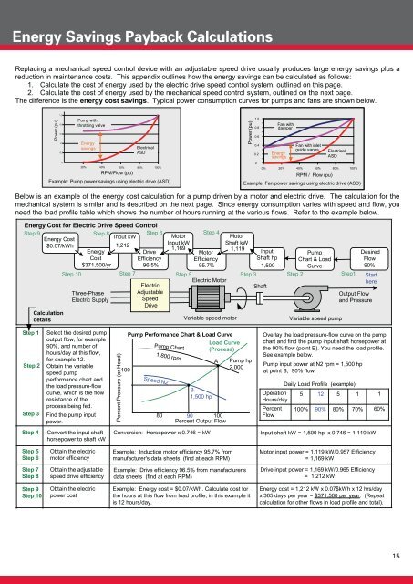
Replacing a mechanical speed control device with an adjustable speed drive usually produces large energy savings plus a<br />
reduction in maintenance costs. This appendix outlines how the energy savings can be calculated as follows:<br />
1. Calculate the cost of energy used by the electric drive speed control system, outlined on this page.<br />
2. Calculate the cost of energy used by the mechanical speed control system, outlined on the next page.<br />
The difference is the energy cost savings. Typical power consumption curves for pumps and fans are shown below.<br />
Power (pu)<br />
1.0<br />
0.8<br />
o<br />
0.6<br />
0.4<br />
0.2<br />
0<br />
Pump with<br />
throttling valve<br />
Energy<br />
savings<br />
o<br />
o<br />
o<br />
o<br />
20% 40% 60% 80% 100%<br />
o<br />
Electrical<br />
ASD<br />
RPM/Flow (pu)<br />
Example: Pump power savings using electric drive (ASD)<br />
Power (pu)<br />
1.0<br />
0.8<br />
0.6<br />
0.4<br />
0.2<br />
0<br />
Fan with<br />
damper<br />
Energy<br />
savings<br />
Fan with inlet<br />
guide vanes<br />
Electrical<br />
ASD<br />
0% 20% 40% 60% 80% 100%<br />
RPM / Flow (pu)<br />
Example: Fan power savings using electric drive (ASD)<br />
Below is an example of the energy cost calculation for a pump driven by a motor and electric drive. The calculation for the<br />
mechanical system is similar and is described on the next page. Since energy consumption varies with speed and flow, you<br />
need the load profile table which shows the number of hours running at the various flows. Refer to the example below.<br />
Energy Cost for Electric Drive Speed Control<br />
Step 9<br />
Step 8<br />
Step 6<br />
Energy Cost<br />
Input kW<br />
$0.07/kWh<br />
1,212<br />
Energy<br />
Drive<br />
Cost<br />
Efficiency<br />
$371,500/yr<br />
96.5%<br />
Step 10<br />
Step 7<br />
Calculation<br />
details<br />
Three-Phase<br />
Electric Supply<br />
Electric<br />
Adjustable<br />
Speed<br />
Drive<br />
Motor<br />
Step 4<br />
Motor<br />
Input kW<br />
Shaft kW<br />
1,169<br />
Motor<br />
1,119<br />
Input<br />
Efficiency<br />
Shaft hp<br />
95.7%<br />
1,500<br />
Step 5<br />
Step 3<br />
Electric Motor<br />
Shaft<br />
Variable speed motor<br />
Pump<br />
Chart & Load<br />
Curve<br />
Step 2<br />
Variable speed pump<br />
Step1<br />
Desired<br />
Flow<br />
90%<br />
Start<br />
here<br />
Output Flow<br />
and Pressure<br />
Step 1<br />
Step 2<br />
Step 3<br />
Select the desired pump<br />
output flow, for example<br />
90%, and number of<br />
hours/day at this flow,<br />
for example 12.<br />
Obtain the variable<br />
speed pump<br />
performance chart and<br />
the load pressure-flow<br />
curve, which is the flow<br />
resistance of the<br />
process being fed.<br />
Find the pump input<br />
power.<br />
Percent Pressure (or Head)<br />
100<br />
Pump Performance Chart & Load Curve<br />
Load Curve<br />
(Process)<br />
Pump Chart<br />
Speed N2<br />
1,800 rpm<br />
80<br />
B<br />
1,500 hp<br />
A<br />
90 100<br />
Percent Output Flow<br />
Pump hp<br />
2,000<br />
Overlay the load pressure-flow curve on the pump<br />
chart and find the pump input shaft horsepower at<br />
the 90% flow (point B). You need the load profile.<br />
See example below.<br />
Pump input power at N2 rpm = 1,500 hp<br />
at point B, 90% flow.<br />
Daily Load Profile (example)<br />
Operation<br />
Hours/day<br />
Percent<br />
Flow<br />
5<br />
100%<br />
12<br />
90%<br />
5<br />
80%<br />
1<br />
70%<br />
1<br />
60%<br />
Step 4<br />
Convert the input shaft<br />
horsepower to shaft kW<br />
Conversion: Horsepower x 0.746 = kW<br />
Input shaft kW = 1,500 hp x 0.746 = 1,119 kW<br />
Step 5<br />
Step 6<br />
Obtain the electric<br />
motor efficiency<br />
Example: Induction motor efficiency 95.7% from<br />
manufacturer's data sheets (find at each RPM)<br />
Motor input power = 1,119 kW/0.957 Efficiency<br />
= 1,169 kW<br />
Step 7<br />
Step 8<br />
Obtain the adjustable<br />
speed drive efficiency<br />
Example: Drive efficiency 96.5% from manufacturer's<br />
data sheets (find at each RPM)<br />
Drive input power = 1,169 kW/0.965 Efficiency<br />
= 1,212 kW<br />
Step 9<br />
Step 10<br />
Obtain the electric<br />
power cost<br />
Example: Energy cost = $0.07/kWh. Calculate cost for<br />
the hours at this flow from load profile; in this example it<br />
is 12 hours/day.<br />
Energy cost = 1,212 kW x 0.07$kWh x 12 hrs/day<br />
x 365 days per year = $371,500 per year. (Repeat<br />
calculation for other flows in load profile and total).<br />
15