nv Series Controller - Tmeic.com
nv Series Controller - Tmeic.com
nv Series Controller - Tmeic.com

Create successful ePaper yourself
Turn your PDF publications into a flip-book with our unique Google optimized e-Paper software.
Unified <strong>Controller</strong> <strong>nv</strong> <strong>Series</strong><br />
Product Application Guide<br />
metals cranes<br />
mining testing oil & gas paper utilities cement
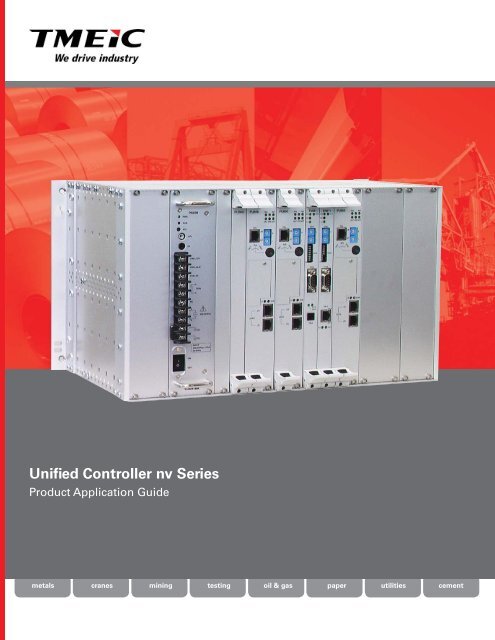
Unified <strong>Controller</strong> <strong>nv</strong> <strong>Series</strong><br />
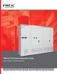
Toshiba’s latest industrial controller, the Unified <strong>nv</strong><br />
<strong>Series</strong> controller, is a big step beyond the existing<br />
V series used in industry around the world. The<br />
capabilities include high-speed logic, sequencing,<br />
motor speed control, and continuous control. Highspeed<br />
I/O <strong>com</strong>munication uses the industry’s first 100<br />
Mbps fault tolerant ring network “TC-net I/O”, linking<br />
remote, field mounted I/O.<br />
The main features of this powerful controller are:<br />
• Fault tolerant ring 100 Mbps I/O <strong>com</strong>munication<br />
• Enhanced speed by direct execution of IEC standard<br />
control languages in ASIC hardware<br />
• Higher reliability using redundant modules, and<br />
error checking and correcting ECC memory<br />
• Gigabit supervisory control network<br />
<strong>nv</strong> <strong>Controller</strong> board,<br />
up to three per chassis<br />
Second <strong>nv</strong> <strong>Controller</strong> TC-net 100 board Ethernet board<br />
Power supply<br />
Third <strong>nv</strong><br />
<strong>Controller</strong><br />
Input/Output LAN TC-net I/O Loop, 100 Mbps<br />
Input/Output LAN TC-net I/O Loop return<br />
System Network - Ethernet, 1 Gbps<br />
Control Network TC-net 100 – Fiber-optic, 100 Mbps<br />
Option: TC-net 1 G - Fiber optic, 1 GBs<br />
Feature<br />
High-speed processing<br />
Short control cycle<br />
Large program capacity<br />
High data capacity<br />
Interrupts<br />
Multiple controllers<br />
Programming flexibility<br />
Memory reliability<br />
Page 2 of 8<br />
Details<br />
Bit and integer processing: 20 ns; floating point add/multiply: 120 ns<br />
Three separately scheduled periodic tasks: 0.5 ms to 1,000 ms<br />
Programs up to 256 kilo steps (instructions), up to 385 periodic programs<br />
Local/global variables 256 K words; I/O variables 16,384 16-bit words<br />
Total of 16 interrupt tasks<br />
Up to three controllers per chassis; up to 4 <strong>com</strong>munication modules; redundant<br />
controller and network configurations possible<br />
Four IEC 61131-3 standard languages: LD, FBD, SFC, and ST<br />
An error-correcting ECC circuit in the internal memory of each module<br />
© 2011 TMEIC Corporation, All Rights Reserved.
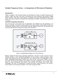
Field Mounted I/O<br />
To reduce hundreds of long wiring runs between the<br />
electrical room and the machinery, the <strong>nv</strong> controller<br />
features field mountable I/O modules <strong>com</strong>municating<br />
with the controller over an optical loop. Using this<br />
approach, wiring material and labor costs can be<br />
greatly reduced. To protect the modules against<br />
conditions close to the machinery, the enclosure<br />
is rated IP54, which gives protection against dust,<br />
vibration, water splash and drips. Field I/O is housed<br />
in cabinets like the one shown below.<br />
Supervisory<br />
Computer<br />
System Network<br />
HMI<br />
- Ethernet<br />
HMI<br />
Server<br />
Control Network TC-net 100<br />
Two networks link the controller with the input/output modules:<br />
• The Electrical ring (blue) services I/O local to the controller<br />
• The Optical ring (red) services field distributed I/O local to the<br />
machinery. Field I/O is housed in the cabinet shown below.<br />
Serial <strong>com</strong>munication<br />
(SIO) Module<br />
<strong>nv</strong> <strong>Controller</strong>s . . . .<br />
Electrooptical<br />
Hub<br />
TC-net I/O optical loop or star<br />
. . . .<br />
. . . .<br />
TMdrive-10<br />
Field I/O<br />
cabinet<br />
M<br />
M<br />
M<br />
Limit<br />
Switch<br />
I/O<br />
. . . .<br />
Solenoid<br />
Valve<br />
Motors<br />
Control system topology<br />
Field I/O cabinet<br />
Field wiring terminals<br />
IO Module<br />
Field Enclosure. The typical field enclosure is 1200<br />
mm wide, 2100 mm high, and 600 mm deep. The<br />
enclosure contains the circuit breakers, power<br />
supplies and other <strong>com</strong>ponents on the left hand side,<br />
and the DIN-rail mounted I/O modules on the right.<br />
The enclosure is rated IP54. Other sizes are available<br />
to suit the application, such as pedestal or wall mount.<br />
Electric Room Enclosure. This is the same size<br />
enclosure used for the field I/O, but with electric<br />
TC-net I/O cabling to the SIO modules. An optical<br />
interface is used if cabling distance requires one.<br />
<strong>Controller</strong> arrangements can be made for up to three<br />
CPUs. This enclosure rating is IP20.<br />
Page 3 of 8<br />
© 2011 TMEIC Corporation, All Rights Reserved.
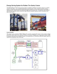
I/O Communications over TC-net I/O<br />
The <strong>nv</strong> series I/O modules can be mounted in the<br />
electrical room or remotely, adjacent to the machinery<br />
or process. TC-net I/O <strong>com</strong>munication with the local<br />
I/O is over an electrical Cat5e fault tolerant ring<br />
(shown in blue), which connects to electrical serial<br />
I/O modules (SIO). Field mounted I/O is connected<br />
using fault tolerant optical rings (shown in red), which<br />
connect to optical SIOs, while the drives typically use<br />
an optical co<strong>nv</strong>erter or hub, (shown in yellow).<br />
Large drives such as the cabinet-mounted TMdrive-<br />
10e2, 30, 50, and 70 are connected in star configuration<br />
to a hub device. Smaller TMdrive-10e2 family drives<br />
mounted in multistage panels share an electrical<br />
multidrop cable using an optical-electrical co<strong>nv</strong>erter<br />
mounted in the drive panel. Other <strong>com</strong>munication<br />
networks such as Modbus and Profibus (shown in<br />
green) can <strong>com</strong>municate over TC-net I/O using special<br />
modules.<br />
<strong>nv</strong> controller<br />
<strong>nv</strong><br />
board<br />
E TC<br />
Net Net<br />
Electrical Room Equipment<br />
Local I/O cabinet<br />
Optical cables:<br />
Each line is two fibers<br />
TC-net I/O Loop HUB<br />
(UTLH21)<br />
Optical fault tolerant ring<br />
Max distance: 2 km<br />
Total distance: 4 km<br />
Electric fault tolerant ring<br />
Max distance: 10 m<br />
Total distance: 100 m<br />
SIO<br />
SIO<br />
SIO<br />
I/O<br />
I/O<br />
I/O<br />
I/O<br />
I/O<br />
I/O<br />
Pulpit Desk<br />
Field Distributed I/O<br />
Optical-Electric<br />
TC-net I/O Loop HUB TC-net I/O Loop HUB<br />
D D D D D D D D D D D D<br />
DRIVE<br />
R RIVE RIVE RIVE RIVE RIVE RIVE RIVE RIVE RIVE RIVE RIVE DRIVE<br />
IVE<br />
DRIVE<br />
(UTLH21)<br />
(UTLH21)<br />
Co<strong>nv</strong>erter<br />
USIO21<br />
DRIVE<br />
M<br />
M<br />
M<br />
M<br />
Optical-Electric<br />
Co<strong>nv</strong>erter<br />
USIO21<br />
DRIVE<br />
DRIVE<br />
DRIVE<br />
DRIVE<br />
M<br />
M<br />
M<br />
M<br />
SIO<br />
I/O<br />
Serial I/O<br />
Interface<br />
I/O<br />
PROFIBUS-DP<br />
Master<br />
SIO<br />
SIO<br />
PA912<br />
I/O<br />
I/O<br />
I/O<br />
I/O<br />
PROFIBUS-<br />
DP Slave<br />
M<br />
M<br />
M<br />
M<br />
M<br />
M<br />
Self-supporting panels<br />
M<br />
M<br />
M<br />
M<br />
M<br />
M<br />
Self-supporting panels<br />
DRIVE<br />
Multistage panel<br />
Max 12 drives<br />
M<br />
DRIVE<br />
Multistage panel<br />
Max 12 drives<br />
M<br />
Variable<br />
speed motors<br />
PROFIBUS-<br />
DP Slave<br />
Field Distributed<br />
I/O cabinet<br />
TC-net I/O Features<br />
Details<br />
Topology<br />
Fault tolerant rings, each cable has a transmit and receive wire or fiber. Any loop<br />
connection can be severed without loss of <strong>com</strong>munication<br />
Data rate<br />
Transmission and reception at 100 Mbps<br />
Number of interfaces 32 SIO interfaces per loop plus up to 200 drives per controller<br />
Serial interfaces, SIO<br />
Electrical SA911; Optical SA912; Profibus DP Master PA912 (optical);<br />
Modbus RTU MD911-M<br />
Number of modules<br />
16 I/O modules per SIO interface<br />
Scan cycle<br />
High-speed scan: 100μsec or more; medium speed scan: 1 ms or more<br />
Cable length<br />
Electrical distance between nodes 10 m (32 ft.); optical distance 2 km (6,550 ft)<br />
Cable type Electrical cable is category 5 shielded twisted pair; optical cable is GI 50/125<br />
Page 4 of 8<br />
© 2011 TMEIC Corporation, All Rights Reserved.
Input/Output I/O Module Family<br />
The the table below shows a partial list of I/O modules with brief specifications. Rack mount versions are also<br />
available.<br />
I/O Module dimensions:<br />
W 35 mm (1.377 in)<br />
H 185 mm (7.28 in)<br />
D 95 mm (3.74 in)<br />
Module and Base dimensions:<br />
W 92 mm (3.62 in)<br />
H 200 mm (7.87 in)<br />
D 115 mm (4.53 in)<br />
External Power Supply:<br />
24 Vdc<br />
Serial I/O Communication<br />
Module<br />
Communicates with up to 16 I/O<br />
modules<br />
Optical SA912 and electrical<br />
SA911 versions available<br />
Redundant serial I/O interfaces<br />
are on option<br />
Module Name Channels Input-Output Description Accuracy Speed<br />
Discrete Input DI934T<br />
DI943S<br />
DI944<br />
DI936<br />
DI937<br />
IN954<br />
IN956<br />
IN966<br />
32<br />
32<br />
32<br />
16<br />
16<br />
32<br />
16<br />
16<br />
24 Vdc<br />
24 Vdc<br />
48 Vdc<br />
12/24 Vdc<br />
24 Vdc<br />
AC/DC 100/120V<br />
AC/DC 100/120V<br />
200/240 Vac<br />
8 ma<br />
5.2 ma with strobe<br />
2.5 ma<br />
9.6 ma, independent pts<br />
9.6 ma, contact input<br />
10.2 mA (100 Vac-50Hz)/13.6 mA(110Vac-60Hz)<br />
15 mA (100 Vac)/2.3 mA (110 Vac)<br />
10 ma (at 200 Vac-50 Hz)<br />
—<br />
—<br />
—<br />
—<br />
—<br />
—<br />
—<br />
—<br />
—<br />
< 1ms<br />
—<br />
< 1ms<br />
< 1ms<br />
—<br />
—<br />
15 ms<br />
Discrete Out<br />
Analog Input<br />
Thermocouple<br />
Resistance TD<br />
Analog<br />
Output<br />
Pulse Output<br />
Resolver Input<br />
DO934<br />
DO934P<br />
DO936<br />
DO933P<br />
AI929D<br />
AI938<br />
AI928<br />
TC919<br />
RT918C<br />
RT918<br />
AO928F<br />
AO938<br />
AO934F<br />
AO954F<br />
PI918<br />
PI924<br />
PI934<br />
PI964<br />
AB932J<br />
AB933J<br />
AB934J<br />
AB932N<br />
AB933N<br />
AB934N<br />
AB935N<br />
AB936N<br />
32<br />
32<br />
16<br />
16<br />
16<br />
8<br />
8<br />
16<br />
8<br />
8<br />
8<br />
4<br />
4<br />
8<br />
4<br />
4<br />
4<br />
2<br />
2<br />
2<br />
2<br />
2<br />
2<br />
2<br />
12-24 Vdc<br />
12-24 Vdc<br />
24 Vdc<br />
24 Vdc<br />
0-20 mA<br />
±10 V<br />
0-20 ma<br />
Thermocouples<br />
Pt100; JPt100<br />
Pt100; JPt100<br />
0-20 ma<br />
-10 to 10 V<br />
-10 to 10 V<br />
-10ma to 10ma<br />
12/24 V<br />
12/24 V<br />
RS485 input<br />
12/24 V<br />
Poscoder<br />
Poscoder<br />
Linear sensor<br />
NSD Abscoder<br />
NSD Abscoder<br />
NSD Linear Abs<br />
JCC Line resolv<br />
JCC Line resolv<br />
Linear Sensor TP912M 2 MTS Temposonics<br />
sensor<br />
Modbus<br />
MD911-M<br />
MD911-S<br />
Modbus-RTU<br />
Modbus-RTU<br />
100 ma sink output<br />
100 ma source output<br />
2.0 A sink out, isolation<br />
2A protected source<br />
Non isolated<br />
Transformer isolation<br />
Transformer isolation<br />
Type B, R, S, J, K, T, E<br />
Platinum RTD<br />
Platinum RTD, isolated<br />
Insulated channels<br />
Non-insulated<br />
Insulated channels<br />
Insulated channels<br />
Gated inputs 50 kHZ<br />
Bipulse input, up-down, 50 kHz<br />
Up/Dn:2.6 MHz, A-Quad-B:650kHz<br />
Versatile A-Quad-B, 50 kHz<br />
Single-turn encoder<br />
Multi-turn encoder<br />
Resolver type linear encoder<br />
Single turn encoder<br />
Multi-turn encoder<br />
Linear encoder<br />
Linear encoder, High resolution<br />
Linear encoder, Medium resolution<br />
—<br />
—<br />
—<br />
—<br />
14 bits, 0.1%<br />
S+13 bits, 0.2%<br />
14 bits, 0.2%<br />
0.1%<br />
±0.1%CJC ±1%<br />
±0.1%<br />
16 bits, 0.1%<br />
13 bits, 0.1%<br />
15 bits, 0.1%<br />
15 bits, 0.1%<br />
—<br />
—<br />
—<br />
—<br />
—<br />
—<br />
—<br />
—<br />
—<br />
—<br />
—<br />
—<br />
< 1ms<br />
< 1ms<br />
< 1ms<br />
—<br />
50ms/16 ch.<br />
0.5ms<br />
0.5ms/8 ch.<br />
0.8s/16 ch.<br />
0.8s/8 ch.<br />
0.8s/8 ch.<br />
1 ms/8 ch.<br />
5 ms/8 ch.<br />
0.175ms/4 ch.<br />
0.175ms/4 ch.<br />
Up to 25-bit data — —<br />
Master module<br />
Slave module<br />
Profibus PA912 Profibus-DP Master module — —<br />
—<br />
—<br />
—<br />
—<br />
—<br />
—<br />
—<br />
—<br />
—<br />
—<br />
—<br />
—<br />
—<br />
—<br />
—<br />
—<br />
Page 5 of 8<br />
© 2011 TMEIC Corporation, All Rights Reserved.
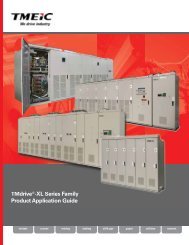
<strong>Controller</strong> Programming<br />
Engineering Tool - choose from four International Standard Programming Languages<br />
The Engineering Tool software for the <strong>nv</strong> <strong>Series</strong> controller provides four IEC-61131-3 standard programming<br />
languages: Ladder Diagrams (LD), Function Block Diagrams (FBD), Sequential Function Charts (SFC), and Structured<br />
Text (ST). The first three can be mixed in the same program and displayed on the same screen.<br />
Ladder Diagrams LD is the preferred programming<br />
language for logic control and sequencing. It shows<br />
relay circuit contacts and coils, and indicates power<br />
flow using color to allow easy test and debug of<br />
logic circuits before actual use.<br />
Sequential Function Charts - SFC charts show the<br />
control flow and the action unit, which shows the<br />
action performed at each step, and the transition<br />
condition unit, which shows the conditions for<br />
advancing to the next step.<br />
Function Block Diagrams - FBDs are a familiar graphical<br />
control representation using function blocks containing<br />
sections of logic or analog control for easy manipulation<br />
and connection. Custom control blocks can be kept for reuse.<br />
Features include high density notations, line crossing<br />
and skip, and return lines.<br />
Mix all three programs on one screen. Using all the<br />
graphical programs offers the best programming<br />
co<strong>nv</strong>enience.<br />
Structured Text Language - ST allows difficult<br />
applications not easily programmed with LDs,<br />
SFCs, or FBDs to be handled with languages<br />
such as Visual Basic or C. Note that Structured<br />
Text cannot be mixed with the other three<br />
languages.<br />
Page 6 of 8<br />
© 2011 TMEIC Corporation, All Rights Reserved.
Operator Accessible Machine Diagnostic Displays<br />
The HMI brings the operator instant feedback on the cause of machinery<br />
problems, and presents the information in an easily understood way to<br />
reduce the time spent diagnosing the problem. During initial programming,<br />
permissive logic blocks, DIAG_D, are entered in the ladder logic program. The<br />
screens show the sequence of events when a machine problem occurs.<br />
1<br />
Immediate Notification<br />
A fault occurs, for example an open limit switch, and a permissive<br />
alarm is created on the operator HMI screen. This fault can<br />
subsequentially cause other faults to occur. When the alarm<br />
button is clicked or touched the permissive overview window is<br />
displayed.<br />
See Associated Groups<br />
2 The permissive overview window shows all permissive<br />
groups associated with the particular function. Faulted<br />
groups are red and displayed at the top. When the faulted<br />
group is clicked or touched, the permissive group window is<br />
displayed.<br />
See Faulted Equipment<br />
3 The permissive group window shows the equipment<br />
in the group, with faulted equipment red and displayed<br />
at the top. When the faulted equipment is clicked or<br />
touched, the permissive variable window is displayed.<br />
Direct Access<br />
In specific cases<br />
diagnostic buttons<br />
can be configured<br />
for direct access to<br />
the root cause<br />
TMEIC’s Library of Control Modules<br />
4<br />
See Problem Interlock<br />
In the permissive variable window, only the<br />
problem interlock conditions are displayed. The<br />
lower ladder logic (Faulted) display shows the first<br />
fault or cause condition, which must be addressed.<br />
The upper present value display (Live) shows all<br />
items which are out of sequence.<br />
5<br />
If required, the original ladder logic program<br />
can be displayed using the Tool cross reference<br />
function.<br />
Engineering Tool contains project-specific control modules developed over 50 years of mill experience. A few<br />
are listed here.<br />
Hot Mill and Cold Mill Function Blocks<br />
• Hydraulic Gap Control<br />
• Gauge Control<br />
• Coiler Automatic Jump Control<br />
• Hydraulic/Electric Interstand Looper Control<br />
• Cold Mill Interstand Tension Control<br />
Process Lines Function Blocks<br />
• Zone Tension control<br />
• Loop Car/Tower control<br />
• Coiler Sequencing control<br />
All-Purpose Function Blocks<br />
• Position Regulator<br />
• Special PID<br />
• Coiler Sequencing Control<br />
POSITION<br />
FORCE<br />
CONTROL<br />
STAND GAP/<br />
FORCE<br />
CONTROL<br />
CYLINDER<br />
REGULATOR<br />
PAYOFF REEL<br />
MOTOR POWER (KW)<br />
INERTIA<br />
+<br />
LOSSES (KW)<br />
FRICTION<br />
+<br />
LOSSES (KW)<br />
BRIDLE 1 ROLL 1<br />
BRIDLE 1 ROLL 2<br />
MOTOR POWER (KW) MOTOR POWER (KW)<br />
INERTIA<br />
INERTIA<br />
+ +<br />
LOSSES (KW)<br />
LOSSES (KW)<br />
FRICTION<br />
FRICTION<br />
+<br />
LOSSES (KW)<br />
LOSSES (KW)<br />
+<br />
FEEDBACK<br />
GAP POSITION<br />
FEEDBACK<br />
FORCE<br />
SENSORS<br />
LOAD CELL /<br />
PRESSURE<br />
TRANSDUCER<br />
Metal Rolling<br />
Gap Control<br />
Block Diagram<br />
X<br />
–<br />
TENSION<br />
POWER (KW)<br />
LS<br />
CONST<br />
ROLL 1 LOAD<br />
CONSTANT (%)<br />
+ +<br />
ROLLS DOWN<br />
X<br />
BRUSHES DOWN<br />
ROLL 1 LOAD<br />
CONSTANT (%)<br />
X<br />
–<br />
X<br />
TENSION<br />
POWER (KW)<br />
LS<br />
CONST<br />
Strip Transport<br />
Tension Control<br />
Block Diagram<br />
FEEDBACK<br />
METAL-IN-<br />
STAND<br />
ZERO (KG)<br />
FLATTENER<br />
LOSSES (KG)<br />
PAYOFF<br />
TENSION (KG)<br />
PRECLEANER<br />
LOSSES (KG)<br />
LS = LINE SPEED (METERS/MINUTE)<br />
Page 7 of 8<br />
© 2011 TMEIC Corporation, All Rights Reserved.
Global Office Locations:<br />
TMEIC Corporation<br />
Roanoke, Virginia, USA<br />
Tel: +1-540-283-2000<br />
Email: info@tmeic.<strong>com</strong><br />
Web: www.tmeic.<strong>com</strong><br />
TOSHIBA MITSUBISHI-ELECTRIC INDUSTRIAL<br />
SYSTEMS CORPORATION<br />
Tokyo, Japan<br />
Tel: +81-3-5441-3828<br />
Web: www.tmeic.co.jp<br />
TMEIC Europe Limited<br />
Uxbridge, Middlesex, United Kingdom<br />
Tel: +44-870-950-7220<br />
Email: info@tmeic.eu<br />
Web: www.tmeic.<strong>com</strong><br />
TMEIC Industrial Systems India Private Limited<br />
Andhra Pradesh, India<br />
Tel +91-40-4034-0000<br />
Web: www.tmeic.in<br />
TOSHIBA MITSUBISHI-ELECTRIC INDUSTRIAL<br />
SYSTEMS CORPORATION<br />
Beijing, China<br />
Tel +86-10-5873-2277<br />
Email: sales@tmeic-cn.<strong>com</strong><br />
Web: www.tmeic-cn.<strong>com</strong><br />
© 2011 TMEIC Corporation, All Rights Reserved.<br />
TOSHIBA MITSUBISHI-ELECTRIC INDUSTRIAL<br />
SYSTEMS CORPORATION<br />
Shanghai, China<br />
Tel: +86-21-6236-0588<br />
Email: sales@tmeic-cn.<strong>com</strong><br />
Web: www.tmeic-cn.<strong>com</strong><br />
TMEIC Asia Company Ltd.<br />
Kowloon Bay, Hong Kong<br />
Tel: +852-2243-3221<br />
Web: www.tmeic.<strong>com</strong><br />
TMEIC Asia Company, Ltd. Rep. Office<br />
Kaohsiung, Taiwan<br />
Tel: +886-7-223-9425<br />
Web: www.tmeic.<strong>com</strong><br />
<strong>nv</strong> <strong>Controller</strong> is covered by U.S. Patent number: USP7.643.888<br />
TC-net 100 has IEC Standard Certification IEC 61784-2 (Real Time Ethernet)<br />
TMdrive is a registered trademark of Toshiba Mitsubishi-Electric Industrial Systems Corporation.<br />
TMEIC is a registered trademark of Toshiba Mitsubishi-Electric Industrial Systems Corporation.<br />
TM is a registered trademark of Toshiba Mitsubishi-Electric Industrial Systems Corporation.<br />
“We drive industry” is a registered trademark of TMEIC Corporation.<br />
All specifications in this document are subject to change without notice. The above brochure is<br />
provided free of charge and without obligation to the reader or to TMEIC Corporation. TMEIC<br />
Corporation does not accept, nor imply, the acceptance of any liability with regard to the use<br />
of the information provided. TMEIC Corporation provides the information included herein as is<br />
and without warranty of any kind, express or implied, including, but not limited to, any implied<br />
statutory warranty of merchantability or fitness for particular purposes. The information is<br />
provided solely as a general reference to the potential benefits that may be attributable to the<br />
technology discussed. Individual results may vary. Independent analysis and testing of each<br />
application is required to determine the results and benefits to be achieved from the technology<br />
discussed.<br />
P-1101