Operating manual SAB 202
Operating manual SAB 202
Operating manual SAB 202

You also want an ePaper? Increase the reach of your titles
YUMPU automatically turns print PDFs into web optimized ePapers that Google loves.
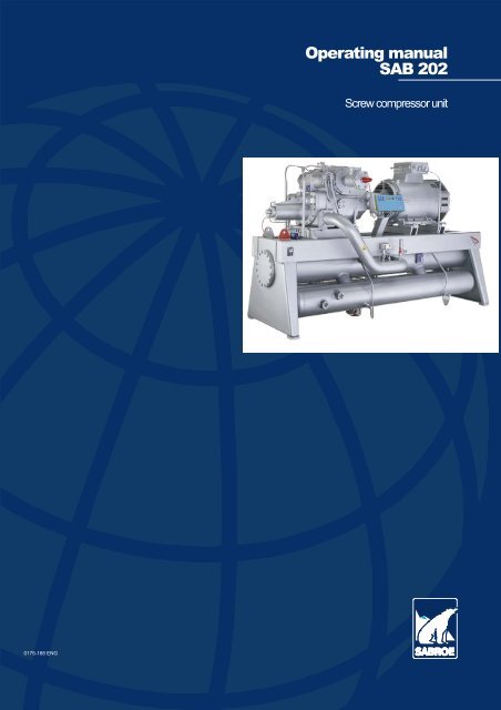
<strong>Operating</strong> <strong>manual</strong><br />
<strong>SAB</strong> <strong>202</strong><br />
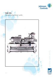
Screw compressor unit<br />
0175-168 ENG
<strong>Operating</strong> Manual - <strong>SAB</strong> <strong>202</strong><br />
Manual for <strong>SAB</strong> <strong>202</strong><br />
The screw compressor and the unit may be fitted<br />
with different equipment, depending on their functions<br />
and requirements.<br />
Part of this equipment is described in this <strong>manual</strong><br />
although it may not be fitted on your particular<br />
unit.<br />
In the table, the x mark indicates which equipment<br />
is fitted on your particular unit with the compressor<br />
number stated below.<br />
Compressor<br />
SM ❏ LM ❏ SF ❏ LF ❏<br />
Compressor no.<br />
Refrigerant ❏ R717 ❏ HFC/HCFC: ______ ❏ Other: ______<br />
Transducers and <strong>manual</strong> regulation of Vi slide<br />
Control<br />
UNI<strong>SAB</strong> II and <strong>manual</strong> regulation of Vi slide<br />
UNI<strong>SAB</strong> II and automatic regulation of Vi slide<br />
Oil filter<br />
Internal<br />
External<br />
Water cooled oil cooler<br />
Oil cooling<br />
❏ OWRF ❏ OWTF Other: ______<br />
Refrigerant cooled oil cooler<br />
OOSI<br />
Refrigerant injection in compressor ❏ HLI ❏ BLI<br />
Oil separator<br />
Oil temp.reg.<br />
Economizer<br />
system<br />
(ECO-system)<br />
With 1 discharge valve<br />
With 2 discharge valves<br />
Thermostatic oil valve<br />
With vessel type<br />
With closed system and vessel type<br />
With open system and vessel type<br />
HESS<br />
EOSE<br />
SVER<br />
Ex-execution<br />
Compressor and unit are<br />
safeguarded<br />
0175-168 - ENG<br />
Rev. 2005.09<br />
1/38
<strong>Operating</strong> Manual - <strong>SAB</strong> <strong>202</strong><br />
Introduction to operating <strong>manual</strong><br />
Introduction to operating <strong>manual</strong><br />
The purpose of this <strong>manual</strong> is to describe:<br />
• Dangers resulting from failure to comply<br />
with safety precautions when operating the<br />
equipment and performing maintenance<br />
tasks.<br />
• How to start, operate and stop the<br />
equipment safely.<br />
• How to act when problems occur during<br />
operation.<br />
• Scheduled maintenance tasks for the<br />
equipment and when/how to carry them<br />
out safely.<br />
This <strong>manual</strong> is primarily intended for operators<br />
and service engineers.<br />
In order to prevent accidents, assembly and disassembly<br />
of components should be carried out by<br />
authorised personnel only.<br />
• It is important that the operating personnel<br />
familiarize themselves with the contents of<br />
this <strong>manual</strong> in order to ensure proper and<br />
efficient operation. Sabroe Refrigeration<br />
(YORK Denmark ApS) - hereafter referred<br />
to as Sabroe Refrigeration - is not liable for<br />
damage occurring during the warranty period<br />
where this is attributable to incorrect operation.<br />
Sabroe Refrigeration's <strong>manual</strong> concept covers six<br />
standard <strong>manual</strong>s: Engineering, <strong>Operating</strong>, Service,<br />
Installation and commissioning, Transport,<br />
and Spare parts.<br />
Therefore, reference may be made to sections<br />
which are not part of this <strong>manual</strong>.<br />
This <strong>manual</strong> is produced by:<br />
Sabroe Refrigeration (YORK Denmark ApS)<br />
Chr. X’s Vej 201, P.O. Box 1810<br />
8270 Højbjerg, Denmark<br />
Phone +45 87 36 70 00<br />
Fax +45 87 36 70 05<br />
www.sabroe.com<br />
Reg. No 19 05 61 71<br />
Copyright © 2004 Sabroe Refrigeration<br />
This <strong>manual</strong> must not be copied without the written<br />
permission of Sabroe Refrigeration and the<br />
contents must not be imparted to a third party nor<br />
be used for any unauthorised purposes.<br />
Contravention will be prosecuted.<br />
In the space below you may enter the name and address of your local Sabroe representative<br />
2/38 0175-168 - ENG<br />
Rev. 2005.09
<strong>Operating</strong> Manual - <strong>SAB</strong> <strong>202</strong><br />
Contents<br />
Manual for <strong>SAB</strong> <strong>202</strong> . . . . . . . . . . . . . . . . . . . . . . . . . . . . . . . . . . . . . . . . . . . . . . . . . . . . . . . . . . . 1<br />
Introduction to operating <strong>manual</strong> . . . . . . . . . . . . . . . . . . . . . . . . . . . . . . . . . . . . . . . . . . . . . . . . . 2<br />
Contents . . . . . . . . . . . . . . . . . . . . . . . . . . . . . . . . . . . . . . . . . . . . . . . . . . . . . . . . . . . . . . . . . . . . 3<br />
Areas of application of screw compressor unit . . . . . . . . . . . . . . . . . . . . . . . . . . . . . . . . . . . . . . . 5<br />
Application . . . . . . . . . . . . . . . . . . . . . . . . . . . . . . . . . . . . . . . . . . . . . . . . . . . . . . . . . . . . . 5<br />
Application of combustion engines . . . . . . . . . . . . . . . . . . . . . . . . . . . . . . . . . . . . . . . . . . . 5<br />
Signs and Warnings . . . . . . . . . . . . . . . . . . . . . . . . . . . . . . . . . . . . . . . . . . . . . . . . . . . . . . . . . . . 6<br />
Identification of Sabroe Refrigeration equipment . . . . . . . . . . . . . . . . . . . . . . . . . . . . . . . . 6<br />
Unit pipe system name plate . . . . . . . . . . . . . . . . . . . . . . . . . . . . . . . . . . . . . . . . . . . . . . . 7<br />
Compressor name plate . . . . . . . . . . . . . . . . . . . . . . . . . . . . . . . . . . . . . . . . . . . . . . . . . . . 8<br />
Vessel name plate . . . . . . . . . . . . . . . . . . . . . . . . . . . . . . . . . . . . . . . . . . . . . . . . . . . . . . . 9<br />
Signs in instructions . . . . . . . . . . . . . . . . . . . . . . . . . . . . . . . . . . . . . . . . . . . . . . . . . . . . . . 10<br />
The sign: CAUTION . . . . . . . . . . . . . . . . . . . . . . . . . . . . . . . . . . . . . . . . . . . . . . . . . . . . . . 10<br />
The sign: HIGH VOLTAGE . . . . . . . . . . . . . . . . . . . . . . . . . . . . . . . . . . . . . . . . . . . . . . . . . 10<br />
The sign: The temperature of tangible surfaces . . . . . . . . . . . . . . . . . . . . . . . . . . . . . . . . . 11<br />
The sign: Internal protection . . . . . . . . . . . . . . . . . . . . . . . . . . . . . . . . . . . . . . . . . . . . . . . . 11<br />
Other warning signs . . . . . . . . . . . . . . . . . . . . . . . . . . . . . . . . . . . . . . . . . . . . . . . . . . . . . . 11<br />
Emergency stop . . . . . . . . . . . . . . . . . . . . . . . . . . . . . . . . . . . . . . . . . . . . . . . . . . . . . . . . . 12<br />
Safety at service . . . . . . . . . . . . . . . . . . . . . . . . . . . . . . . . . . . . . . . . . . . . . . . . . . . . . . . . . 12<br />
Warnings in instructions . . . . . . . . . . . . . . . . . . . . . . . . . . . . . . . . . . . . . . . . . . . . . . . . . . . 13<br />
Texts marked with Danger! . . . . . . . . . . . . . . . . . . . . . . . . . . . . . . . . . . . . . . . . . . . . . . . . . 13<br />
Texts marked with Warning! . . . . . . . . . . . . . . . . . . . . . . . . . . . . . . . . . . . . . . . . . . . . . . . . 13<br />
Texts marked with Caution! . . . . . . . . . . . . . . . . . . . . . . . . . . . . . . . . . . . . . . . . . . . . . . . . 13<br />
Safety precautions . . . . . . . . . . . . . . . . . . . . . . . . . . . . . . . . . . . . . . . . . . . . . . . . . . . . . . . . . . . . 14<br />
General safety instructions and considerations . . . . . . . . . . . . . . . . . . . . . . . . . . . . . . . . . 14<br />
Personal safety . . . . . . . . . . . . . . . . . . . . . . . . . . . . . . . . . . . . . . . . . . . . . . . . . . . . . . . . . . 14<br />
Work area safety . . . . . . . . . . . . . . . . . . . . . . . . . . . . . . . . . . . . . . . . . . . . . . . . . . . . . . . . . 14<br />
Tool safety . . . . . . . . . . . . . . . . . . . . . . . . . . . . . . . . . . . . . . . . . . . . . . . . . . . . . . . . . . . . . 14<br />
Operation safety . . . . . . . . . . . . . . . . . . . . . . . . . . . . . . . . . . . . . . . . . . . . . . . . . . . . . . . . . 15<br />
Maintenance safety . . . . . . . . . . . . . . . . . . . . . . . . . . . . . . . . . . . . . . . . . . . . . . . . . . . . . . . 15<br />
Lubricating oils . . . . . . . . . . . . . . . . . . . . . . . . . . . . . . . . . . . . . . . . . . . . . . . . . . . . . . . . . . 17<br />
Refrigerants . . . . . . . . . . . . . . . . . . . . . . . . . . . . . . . . . . . . . . . . . . . . . . . . . . . . . . . . . . . . 17<br />
Cooling water systems . . . . . . . . . . . . . . . . . . . . . . . . . . . . . . . . . . . . . . . . . . . . . . . . . . . . 17<br />
Noise data for screw compressors . . . . . . . . . . . . . . . . . . . . . . . . . . . . . . . . . . . . . . . . . . . 18<br />
<strong>Operating</strong> instructions . . . . . . . . . . . . . . . . . . . . . . . . . . . . . . . . . . . . . . . . . . . . . . . . . . . . . . . . . 19<br />
Safety precautions . . . . . . . . . . . . . . . . . . . . . . . . . . . . . . . . . . . . . . . . . . . . . . . . . . . . . . . 19<br />
Ventilation . . . . . . . . . . . . . . . . . . . . . . . . . . . . . . . . . . . . . . . . . . . . . . . . . . . . . . . . . . . . . . 19<br />
Pressure . . . . . . . . . . . . . . . . . . . . . . . . . . . . . . . . . . . . . . . . . . . . . . . . . . . . . . . . . . . . . . . 19<br />
Hot and cold surfaces . . . . . . . . . . . . . . . . . . . . . . . . . . . . . . . . . . . . . . . . . . . . . . . . . . . . . 19<br />
UNI<strong>SAB</strong> II reading, safety and capacity regulating system . . . . . . . . . . . . . . . . . . . . . . . . 19<br />
Valves for operating the compressor . . . . . . . . . . . . . . . . . . . . . . . . . . . . . . . . . . . . . . . . . 20<br />
0175-168 - ENG<br />
Rev. 2005.09<br />
3/38
<strong>Operating</strong> Manual - <strong>SAB</strong> <strong>202</strong><br />
Preparations before start . . . . . . . . . . . . . . . . . . . . . . . . . . . . . . . . . . . . . . . . . . . . . . . . . . . 21<br />
Starting . . . . . . . . . . . . . . . . . . . . . . . . . . . . . . . . . . . . . . . . . . . . . . . . . . . . . . . . . . . . . . . . . 21<br />
Principle drawing - position during operation . . . . . . . . . . . . . . . . . . . . . . . . . . . . . . . . . . . . 23<br />
Checks to be performed during operation . . . . . . . . . . . . . . . . . . . . . . . . . . . . . . . . . . . . . . 24<br />
Operations log . . . . . . . . . . . . . . . . . . . . . . . . . . . . . . . . . . . . . . . . . . . . . . . . . . . . . . . . . . . 25<br />
Stopping routine . . . . . . . . . . . . . . . . . . . . . . . . . . . . . . . . . . . . . . . . . . . . . . . . . . . . . . . . . . 26<br />
Brief stop . . . . . . . . . . . . . . . . . . . . . . . . . . . . . . . . . . . . . . . . . . . . . . . . . . . . . . . . . . . . . . . 26<br />
Shutting down for long idle period . . . . . . . . . . . . . . . . . . . . . . . . . . . . . . . . . . . . . . . . . . . . 26<br />
Problems . . . . . . . . . . . . . . . . . . . . . . . . . . . . . . . . . . . . . . . . . . . . . . . . . . . . . . . . . . . . . . . 26<br />
Fault finding . . . . . . . . . . . . . . . . . . . . . . . . . . . . . . . . . . . . . . . . . . . . . . . . . . . . . . . . . . . . . 26<br />
Maintenance instructions . . . . . . . . . . . . . . . . . . . . . . . . . . . . . . . . . . . . . . . . . . . . . . . . . . . . . . . 27<br />
Maintenance of the compressor unit . . . . . . . . . . . . . . . . . . . . . . . . . . . . . . . . . . . . . . . . . . 27<br />
General . . . . . . . . . . . . . . . . . . . . . . . . . . . . . . . . . . . . . . . . . . . . . . . . . . . . . . . . . . . . . . . . 27<br />
Major service intervals . . . . . . . . . . . . . . . . . . . . . . . . . . . . . . . . . . . . . . . . . . . . . . . . . . . . . 28<br />
Checking the oil . . . . . . . . . . . . . . . . . . . . . . . . . . . . . . . . . . . . . . . . . . . . . . . . . . . . . . . . . . 29<br />
Visual inspection . . . . . . . . . . . . . . . . . . . . . . . . . . . . . . . . . . . . . . . . . . . . . . . . . . . . . . . . . 30<br />
Oil level . . . . . . . . . . . . . . . . . . . . . . . . . . . . . . . . . . . . . . . . . . . . . . . . . . . . . . . . . . . . . . . . 30<br />
Oil level glass . . . . . . . . . . . . . . . . . . . . . . . . . . . . . . . . . . . . . . . . . . . . . . . . . . . . . . . . . . . . 30<br />
Oil change . . . . . . . . . . . . . . . . . . . . . . . . . . . . . . . . . . . . . . . . . . . . . . . . . . . . . . . . . . . . . . 30<br />
Oil charging . . . . . . . . . . . . . . . . . . . . . . . . . . . . . . . . . . . . . . . . . . . . . . . . . . . . . . . . . . . . . 31<br />
Motor lubrication . . . . . . . . . . . . . . . . . . . . . . . . . . . . . . . . . . . . . . . . . . . . . . . . . . . . . . . . . 34<br />
Replacing motor bearings . . . . . . . . . . . . . . . . . . . . . . . . . . . . . . . . . . . . . . . . . . . . . . . . . . 34<br />
Major overhaul of the compressor . . . . . . . . . . . . . . . . . . . . . . . . . . . . . . . . . . . . . . . . . . . . 34<br />
Final disposal . . . . . . . . . . . . . . . . . . . . . . . . . . . . . . . . . . . . . . . . . . . . . . . . . . . . . . . . . . . . . . . . 35<br />
Safety precautions . . . . . . . . . . . . . . . . . . . . . . . . . . . . . . . . . . . . . . . . . . . . . . . . . . . . . . . . 35<br />
Disposal of machine parts . . . . . . . . . . . . . . . . . . . . . . . . . . . . . . . . . . . . . . . . . . . . . . . . . . 35<br />
Disposal of oil and refrigerant . . . . . . . . . . . . . . . . . . . . . . . . . . . . . . . . . . . . . . . . . . . . . . . 35<br />
Disposal of electrical components . . . . . . . . . . . . . . . . . . . . . . . . . . . . . . . . . . . . . . . . . . . . 35<br />
Disposal of batteries . . . . . . . . . . . . . . . . . . . . . . . . . . . . . . . . . . . . . . . . . . . . . . . . . . . . . . 35<br />
Appendices . . . . . . . . . . . . . . . . . . . . . . . . . . . . . . . . . . . . . . . . . . . . . . . . . . . . . . . . . . . . . . . . . . 36<br />
References to instructions . . . . . . . . . . . . . . . . . . . . . . . . . . . . . . . . . . . . . . . . . . . . . . . . . . 36<br />
Index . . . . . . . . . . . . . . . . . . . . . . . . . . . . . . . . . . . . . . . . . . . . . . . . . . . . . . . . . . . . . . . . . . . . . . . 37<br />
4/38 0175-168 - ENG<br />
Rev. 2005.09
<strong>Operating</strong> Manual - <strong>SAB</strong> <strong>202</strong><br />
Areas of application of screw compressor unit<br />
Areas of application of screw compressor unit<br />
Application<br />
To prevent unintentional application of the compressor,<br />
which could injure personnel or damage<br />
the equipment, the following must be observed:<br />
• The compressor must only be used as a refrigeration<br />
compressor with the number of<br />
revolutions per minute and within the operating<br />
limits specified in the <strong>manual</strong>s or in a<br />
written agreement with<br />
Sabroe Refrigeration.<br />
• The compressor must only be used with the<br />
following refrigerants: R717, R22, R134a,<br />
R404A, R507, R600, R600A, R290 and<br />
LPG. Other HFC refrigerants must only be<br />
used in accordance with<br />
Sabroe Refrigeration's instructions. All other<br />
types of gas must only be used with a<br />
written permission from<br />
Sabroe Refrigeration.<br />
• The compressors are approved for application<br />
in potentially explosive atmospheres<br />
provided they have been fitted with explosion-proof<br />
equipment. This can be seen<br />
from the Ex name plates fixed on each unit.<br />
See Fig. 1.<br />
Fig. 1<br />
Please note that special tools which do not cause<br />
any sparks must be used for ALL maintenance<br />
work on the compressor.<br />
WWarning!<br />
The compressor must NOT be used:<br />
• For evacuating the refrigeration plant of<br />
air and moisture.<br />
• For putting the refrigeration plant under<br />
air pressure in view of a pressure testing.<br />
• As an air compressor.<br />
W Warning!<br />
Sabroe Refrigeration is not liable for injuries to<br />
personnel or damage to equipment resulting from<br />
using the equipment for other purposes than the<br />
ones stated above.<br />
Application of combustion engines<br />
If combustion engines are installed in rooms containing<br />
refrigeration machinery or rooms where<br />
there are pipes and components containing refrigerant,<br />
make sure that in case of leakage the combustion<br />
air for the engine comes from an area in<br />
which there is no refrigerant gas.<br />
Failure to do so involves a risk of lubricating oil<br />
from the combustion engine mixing with refrigerant.<br />
At worst this may lead to corrosion and damage<br />
of the engine.<br />
0175-168 - ENG<br />
Rev. 2005.09<br />
5/38
<strong>Operating</strong> Manual - <strong>SAB</strong> <strong>202</strong><br />
Signs and Warnings<br />
Signs and Warnings<br />
Identification of Sabroe Refrigeration equipment<br />
All Sabroe Refrigeration equipment can be identified by one or several name plates positioned as illustrated<br />
in the following drawing:<br />
Fig. 2<br />
<strong>SAB</strong> <strong>202</strong> screw compressor unit, position of name plates<br />
1<br />
3<br />
2<br />
1. Compressor name plate<br />
2. Vessel name plate<br />
3. Unit pipe system name plate<br />
6/38 0175-168 - ENG<br />
Rev. 2005.09
<strong>Operating</strong> Manual - <strong>SAB</strong> <strong>202</strong><br />
Signs and Warnings<br />
Unit pipe system name plate<br />
Fig. 3<br />
Unit pipe system name plate<br />
The unit pipe system name plate is positioned on<br />
the frame. The name plate contains the following<br />
information:<br />
• Type<br />
Manufacturer's type designation.<br />
• Year<br />
Year of manufacture.<br />
• Identification no.<br />
Individual no. for identification of supplied<br />
pipe system.<br />
• Design code<br />
For PED orders: EN 378-2<br />
If the unit has been approved by an authority,<br />
the design code will be shown here.<br />
• Approval no.<br />
If the unit has been approved by an authority,<br />
the approval no. will be shown here.<br />
• Pressure system<br />
Low pressure side of compressor piping is<br />
referred to as LP.<br />
High pressure side of compressor piping is<br />
referred to as HP.<br />
• Fluid/Group<br />
Refrigerant designation according to<br />
ISO817 or fluid group according to directive<br />
67/548/EEC.<br />
• Max. allowable pressure, PS<br />
Shows max allowable pressure relative to<br />
atmospheric pressure for which the pipe<br />
system has been designed.<br />
• Leak test pressure, PT<br />
Shows the pressure with which the pipe system<br />
has been leak tested.<br />
• Design temperature, TS<br />
Shows min and max temperatures for which<br />
the pipe system including components has<br />
been designed.<br />
• CE xxxx<br />
The four digits compose the registration no.<br />
of the notified body in charge of the assessment<br />
modules for the vessel.<br />
0175-168 - ENG<br />
Rev. 2005.09<br />
7/38
<strong>Operating</strong> Manual - <strong>SAB</strong> <strong>202</strong><br />
Signs and Warnings<br />
Compressor name plate<br />
Fig. 4 Compressor name plate<br />
The compressor name plate is positioned on the<br />
compressor. The plate contains the following information:<br />
• Compressor no.<br />
Compressor manufacturing number.<br />
• Year<br />
Year of manufacture.<br />
• Type<br />
Manufacturer's type designation.<br />
• Nominal speed<br />
Shows rotational speed of drive shaft at typical<br />
running condition.<br />
• Swept volume<br />
Shows swept volume of compressor in m 3 /h<br />
at nominal speed.<br />
• Max allowable pressure, Ps<br />
Shows max. working pressure of compressor.<br />
• Max allowable pressure, Pss<br />
Shows max allowable pressure at compressor<br />
standstill.<br />
8/38 0175-168 - ENG<br />
Rev. 2005.09
<strong>Operating</strong> Manual - <strong>SAB</strong> <strong>202</strong><br />
Signs and Warnings<br />
Vessel name plate<br />
Fig. 5 Vessel name plate<br />
The vessel name plate is positioned on the shell<br />
of the vessel. The name plate contains the following<br />
information:<br />
• Vessel no.<br />
Vessel number stated by<br />
Sabroe Refrigeration.<br />
• Year<br />
Year of manufacture.<br />
/ /<br />
/ /<br />
• Type<br />
Manufacturer's type designation.<br />
• Design code<br />
Shows the design code according to which<br />
the vessel was manufactured.<br />
• Approval no./CAT<br />
Shows the approval no. of the vessel issued<br />
by the relevant authority as well as the category<br />
according to PED 97/23/EEC,<br />
Article 9.<br />
• Side<br />
Refers to the columns “Shell” and “Tube”.<br />
• Fluid<br />
Shows the refrigerant designation according<br />
to ISO817.<br />
• Allowable pressure, PS<br />
Shows min and max pressure relative to atmospheric<br />
pressure for which the vessel or<br />
vessel part has been designed.<br />
• Allowable temperature, TS<br />
Shows min and max temperatures for which<br />
the vessel has been designed.<br />
• Volume<br />
Shows volume of the vessel in litres.<br />
• CE xxxx<br />
The four digits compose the registration no.<br />
of the notified body in charge of the assessment<br />
modules for the vessel.<br />
0175-168 - ENG<br />
Rev. 2005.09<br />
9/38
<strong>Operating</strong> Manual - <strong>SAB</strong> <strong>202</strong><br />
Signs and Warnings<br />
In the following section, all signs which may<br />
be found on the equipment are described. The<br />
number of signs, however, may vary from<br />
product to product.<br />
Signs in instructions<br />
The sign: CAUTION<br />
A CAUTION tag like the one illustrated below is<br />
fixed to the compressor. The sign imposes the users<br />
to read the Safety precautions chapter in the<br />
<strong>manual</strong> before handling, operating, or servicing<br />
the compressor and unit.<br />
Caution<br />
The sign: HIGH VOLTAGE<br />
WDanger<br />
HIGH VOLTAGE!<br />
Before working on any electrical circuits, turn the<br />
main switch “OFF” and lock it. Dismantle the main<br />
fuses to the compressor unit.<br />
Unless expressly stated in applicable<br />
Sabroe Refrigeration documentation or by a<br />
Sabroe Refrigeration field service representative,<br />
do NOT work with the electrical power “ON”. Any<br />
work with the electrical power “ON” should be performed<br />
by a Sabroe Refrigeration field service<br />
representative. The customer and subsequent<br />
transferees must make sure that any other person<br />
performing work with the electrical power “ON” is<br />
trained and technically qualified.<br />
Before handling, installing, operating, or<br />
servicing the compressor and unit, read<br />
the Safety precautions chapter in the<br />
<strong>Operating</strong> <strong>manual</strong>.<br />
It is the responsibility of the operator or<br />
his employer that the <strong>Operating</strong> <strong>manual</strong><br />
is always available.<br />
This sign must not be removed nor be<br />
damaged in any way.<br />
Antes de manejer, instalar, poner en marcha<br />
o dar servicio al compresor y la unidad,<br />
leer la sección Precauciones de<br />
seguridad en el Libro de Instrucciones.<br />
Es respondabilidad del operarío o de su<br />
patrón, que el libro de instrucciones<br />
permanezca siempre al alcance de la<br />
mano.<br />
Estaseñalnodebedeningunamanera<br />
suprimirse o dañarse. 2516-297<br />
10/38 0175-168 - ENG<br />
Rev. 2005.09
<strong>Operating</strong> Manual - <strong>SAB</strong> <strong>202</strong><br />
Signs and Warnings<br />
The sign: The temperature of tangible<br />
surfaces<br />
When a compressor is working, the surfaces<br />
which are in contact with the warm discharge gas<br />
will also get warm. However, the temperature depends<br />
on the refrigerants used as well as the operating<br />
conditions of the compressor. Often the<br />
temperature exceeds 70°C [158°F], which for<br />
metal surfaces may cause skin burns even at a<br />
light touch.<br />
Consequently, the compressors are equipped<br />
with yellow warning signs signalling that pipes,<br />
vessels, and machine parts will become so hot<br />
during operation that your skin will get burnt if you<br />
touch them for one second or more.<br />
Other warning signs<br />
Hazardous substance!<br />
Dangerous noise level,<br />
use hearing protectors!<br />
Internal overpressure!<br />
Cold surfaces!<br />
The sign: Internal protection<br />
Compressor blocks and units are usually delivered<br />
without any refrigerant or oil.<br />
To protect the compressors against internal corrosion,<br />
they are delivered evacuated of all atmospheric<br />
air and charged with Nitrogen (N 2 ) to an<br />
overpressure of 0.2 bar [3 psi].<br />
In such cases a yellow sign is affixed to a visible<br />
spot on the compressor.<br />
Påfyldt beskyttelsesgas<br />
Charged with inert gas<br />
Enthält Schutzgas<br />
Chargé du gaz protecteur<br />
Contiene gas protector<br />
N 2<br />
0,2 bar<br />
3 PSI<br />
1534-169<br />
0175-168 - ENG<br />
Rev. 2005.09<br />
11/38
<strong>Operating</strong> Manual - <strong>SAB</strong> <strong>202</strong><br />
Signs and Warnings<br />
Emergency stop<br />
Fig. 6<br />
Emergency stop<br />
UNI<strong>SAB</strong><br />
Safety at service<br />
Emergency stop<br />
Before dismantling or servicing a compressor or<br />
unit, attention should be paid to the following<br />
points:<br />
• Read the section Safety precautions in this<br />
<strong>manual</strong> before opening the compressor and<br />
other parts of the refrigeration plant.<br />
• Make sure that the motor cannot start up<br />
inadvertently. It is recommended to remove<br />
all main fuses.<br />
• Switch off all electric components on the<br />
compressor/unit before the dismantling/servicing.<br />
• Make sure that there is neither overpressure<br />
nor any refrigerant in the part to be dismantled.<br />
Close all necessary stop valves.<br />
• Use appropriate gloves as well as eye and<br />
face protection and make sure to have a gas<br />
mask ready for use.<br />
• Use the prescribed tools and check that<br />
they are properly maintained and in good<br />
working condition. In ATEX classified areas,<br />
use tools especially suited for this purpose.<br />
12/38 0175-168 - ENG<br />
Rev. 2005.09
<strong>Operating</strong> Manual - <strong>SAB</strong> <strong>202</strong><br />
Signs and Warnings<br />
Warnings in instructions<br />
This section describes warnings used in instructions<br />
pertaining to Sabroe Refrigeration equipment.<br />
Information of importance to the safety of personnel<br />
or equipment is given at three levels.<br />
• Danger!<br />
• Warning!<br />
• Caution!<br />
There is an important distinction between these<br />
three levels. As shown below, however, the principle<br />
is the same at all three levels.<br />
Note: Information is sometimes given in a note. A<br />
note is used to emphasize information but is never<br />
used for information vital to the safety of personnel<br />
and equipment.<br />
Texts marked with Danger!<br />
The example below shows how information vital to<br />
the safety of involved personnel is presented.<br />
WDanger!<br />
Risk of electrical shock! Always turn off the main<br />
switch before servicing the unit! Contact with high<br />
voltage may cause death or serious injury.<br />
Failure to observe information marked with Danger!<br />
may cause death or serious injury to personnel<br />
or even to a third party.<br />
Texts marked with Warning!<br />
The example below shows how information of importance<br />
to the safety of involved personnel or of<br />
major importance to the safety of equipment is<br />
presented.<br />
WWarning!<br />
Risk of damage to compressor! Always consult<br />
your supplier before using a compressor under<br />
operating conditions outside the specified working<br />
range.<br />
Texts marked with Caution!<br />
The example below shows how information of importance<br />
to the safety of equipment is presented.<br />
WCaution!<br />
Risk of incorrect viscosity! Always make sure that<br />
all oils used are mixable without causing chemical<br />
reactions. Chemical reactions might have serious<br />
effects on the viscosity.<br />
Failure to observe information marked with Caution!<br />
may cause damage to equipment.<br />
0175-168 - ENG<br />
Rev. 2005.09<br />
13/38
<strong>Operating</strong> Manual - <strong>SAB</strong> <strong>202</strong><br />
Safety precautions<br />
Safety precautions<br />
Important!<br />
The safety precautions for this Sabroe compressor<br />
have been prepared to assist the operator,<br />
programmer, and maintenance personnel in practising<br />
good shop safety procedures.<br />
Operator and maintenance personnel must read<br />
and understand these precautions completely before<br />
operating, setting up, running, or performing<br />
maintenance on the compressor/unit.<br />
These precautions are to be used as a supplement<br />
to the safety precautions and warnings included<br />
in:<br />
a. All other <strong>manual</strong>s pertaining to the compressor/unit.<br />
b. Local, plant, and shop safety rules and<br />
codes.<br />
c. National safety rules and regulations.<br />
General safety instructions and<br />
considerations<br />
Personal safety<br />
Owners, operators, maintenance, and service<br />
personnel must make constant day-to-day safety<br />
procedures a vital part of their job. Accident prevention<br />
must be one of the principal objectives of<br />
their job, regardless of the activity involved.<br />
Know and respect the compressor/unit. Read and<br />
carry out the prescribed safety and checking procedures.<br />
Make sure that everyone working for, with or near<br />
you fully understands and - most importantly -<br />
complies with the following safety precautions and<br />
procedures when operating the compressor/unit.<br />
Observe the safety warnings on the compressor/unit.<br />
Use safety equipment. Wear appropriate gloves<br />
as well as eye and face protection when working<br />
with parts containing refrigerant and/or lubricating<br />
oil. Safety shoes with slip-proof soles can help<br />
avoid injuries. Keep safety equipment in good<br />
condition.<br />
Never operate or service this equipment under the<br />
influence of alcohol, drugs or other substances or<br />
if in a condition which decreases alertness or impairs<br />
judgment.<br />
Work area safety<br />
Always keep your work area clean. Dirty work areas<br />
with such hazards as oil, debris or water on<br />
the floor may cause someone to fall on the floor,<br />
into the machine or onto other objects resulting in<br />
serious personal injury.<br />
Make sure your work area is free of hazardous obstructions<br />
and be aware of protruding machine<br />
parts.<br />
Always keep your work area tidy so that you can<br />
escape in case of a dangerous situation.<br />
Report any unsafe working conditions to your supervisor<br />
or safety department.<br />
Tool safety<br />
Always make sure that hand tools are in proper<br />
working condition.<br />
Remove hand tools such as wrenches, measuring<br />
equipment, hammers, etc. from the compressor/unit<br />
immediately after use.<br />
14/38 0175-168 - ENG<br />
Rev. 2005.09
<strong>Operating</strong> Manual - <strong>SAB</strong> <strong>202</strong><br />
Safety precautions<br />
Operation safety<br />
Read and understand all safety instructions before<br />
setting up, operating, or servicing the compressor.<br />
Assign only qualified personnel instructed<br />
in safety and all machine functions to operate<br />
or service this compressor.<br />
Operators and maintenance personnel must carefully<br />
read, understand and fully comply with all<br />
warnings and instruction plates mounted on the<br />
machine. Do not paint over, alter or deface these<br />
plates or remove them from the compressor/unit.<br />
Replace all plates which become illegible. Replacement<br />
plates can be purchased from<br />
Sabroe Refrigeration.<br />
WWarning!<br />
Safety guards, shields, barriers, covers and protective<br />
devices must not be removed while the<br />
compressor/unit is operating.<br />
WWarning!<br />
All safety features, disengagement and interlocks<br />
must be in place and function correctly before the<br />
equipment is put in operation. Never bypass or<br />
wire around any safety device.<br />
Keep all parts of your body off the compressor/motor/unit<br />
during operation. Never lean on or<br />
reach over the compressor.<br />
During operation, pay attention to the compressor<br />
unit process. Excessive vibration, unusual<br />
sounds, etc. can indicate problems requiring your<br />
immediate attention.<br />
Maintenance safety<br />
Do not attempt to perform maintenance on the<br />
compressor unit until you have read and understood<br />
all the safety instructions.<br />
Assign only qualified service or maintenance personnel<br />
to perform maintenance and repair work<br />
on the unit. They must be trained by<br />
Sabroe Refrigeration or be similarly qualified according<br />
to EN 378. They should consult the service<br />
<strong>manual</strong> before attempting any service or repair<br />
work and contact Sabroe Refrigeration in case of<br />
questions. Use only Sabroe Refrigeration original<br />
spare parts; other parts may impair the safety of<br />
the compressor/unit.<br />
Before removing or opening any electrical enclosures,<br />
covers, plates, or doors make sure that the<br />
main switch is in the O position and the main<br />
fuses are dismantled. If possible, post a sign at<br />
the switch indicating that maintenance is being<br />
performed. Dismantle the main fuses to the unit.<br />
W Danger<br />
HIGH VOLTAGE!<br />
Before working on any electrical circuits, place<br />
the main switch of the compressor/unit in the<br />
"OFF" position and lock it. Dismantle the main<br />
fuses to the compressor unit. Unless expressly<br />
stated in applicable Sabroe Refrigeration documentation<br />
or by appropriate<br />
Sabroe Refrigeration field service representative,<br />
do NOT work with the electrical power<br />
"ON". If such express statement or advice exists,<br />
work with the electrical power "ON"<br />
should be performed by a<br />
Sabroe Refrigeration field service representative.<br />
The customer and subsequent transferees<br />
must make sure that any other person performing<br />
work with the electrical power "ON" is<br />
trained and technically qualified.<br />
FAILURE TO FOLLOW THIS INSTRUCTION<br />
MAY RESULT IN DEATH OR SERIOUS<br />
ELECTRIC SHOCK.<br />
0175-168 - ENG<br />
Rev. 2005.09<br />
15/38
<strong>Operating</strong> Manual - <strong>SAB</strong> <strong>202</strong><br />
Safety precautions<br />
When maintenance is to be performed in an area<br />
far away from the main switch and the switch is<br />
not locked, all start buttons must be tagged with<br />
“DO NOT START” tags.<br />
Adequate precautions such as warning notices or<br />
other equally effective means must be taken to<br />
prevent electrical equipment from being activated<br />
when maintenance work is being performed.<br />
When removing electrical equipment, place a<br />
number or a labelled tag on all wires which are not<br />
already marked. If wiring is replaced, make sure<br />
that the new wiring is the same type, length, size<br />
and has the same current carrying capacity.<br />
Close and fasten all guards, shields, covers,<br />
plates, and doors securely before reconnecting<br />
power.<br />
An electrician must analyse the electrical system<br />
to determine the possible use of power retaining<br />
devices such as capacitors. Such power retaining<br />
devices must be disconnected, discharged or<br />
made safe before maintenance is performed.<br />
Working space around electrical equipment must<br />
be clear of obstructions.<br />
Always provide adequate lighting for work and<br />
maintenance to be carried out.<br />
16/38 0175-168 - ENG<br />
Rev. 2005.09
<strong>Operating</strong> Manual - <strong>SAB</strong> <strong>202</strong><br />
Safety precautions<br />
Lubricating oils<br />
WWarning!<br />
When charging oil, follow the safety instructions<br />
given by the oil supplier (MSDS: Material Safety<br />
Data Sheet). Always avoid direct contact with the<br />
oil as this may cause skin allergies. Always use<br />
protective equipment - goggles and gloves - when<br />
charging oil.<br />
Refrigeration compressors are lubricated by one<br />
of the following oil types depending on the refrigerant<br />
plant type, and operating conditions.<br />
– Mineral oil (M oil)<br />
– Alkyl benzene-based synthetic oil (A oil)<br />
– Polyalphaolefine-based synthetic oil<br />
(PAO oil)<br />
– Mixed A and PAO oil (AP oil)<br />
– Polyalkylen glycol-based synthetic oil<br />
(PAG oil)<br />
– Ester oil (E oil)<br />
See the section Selecting lubricating oil for<br />
Sabroe Refrigeration compressors in the oil recommendation<br />
for Sabroe compressors.<br />
When changing oil on the compressor or draining<br />
oil from the vessel of the refrigeration plant, always<br />
collect the used oil in containers marked<br />
“waste oil” and send them to an approved incineration<br />
plant. It is not recommended to reuse oil.<br />
Refrigerants<br />
Great caution must be exercised when dealing<br />
with refrigerants. The supplier of the refrigeration<br />
plant has a duty to inform user and operator about<br />
the dangers of the refrigerant used. Safety data<br />
sheets etc. must be available to the operator.<br />
Cooling water systems<br />
WWarning!<br />
The recirculation water system may contain<br />
chemicals or biological contaminants, including<br />
legionella, which can be harmful if inhaled or ingested.<br />
Water systems should only be operated<br />
with an effective biological treatment programme.<br />
Note:<br />
These instructions only provide general information. The owner of the refrigeration plant is<br />
responsible for ensuring that all codes, regulations, and industry standards are complied with.<br />
0175-168 - ENG<br />
Rev. 2005.09<br />
17/38
<strong>Operating</strong> Manual - <strong>SAB</strong> <strong>202</strong><br />
Safety precautions<br />
Noise data for screw compressors<br />
Evaporating temperature = -15°C<br />
Condensing temperature = +35°C<br />
Refrigerant<br />
= R22/R717<br />
Number of revolutions = 2950 rpm.<br />
*Number of revolutions<br />
= 6000 rpm.<br />
Evaporating temperature<br />
Condensing temperature<br />
Refrigerant<br />
Number of revolutions<br />
= -35°C<br />
= -5°C<br />
= R22/R717<br />
= 2950 rpm.<br />
Compressor block LW LP<br />
Compressor unit LW LP<br />
Mk1<br />
<strong>SAB</strong> 110 SM<br />
<strong>SAB</strong> 110 SF<br />
<strong>SAB</strong> 110 LM<br />
<strong>SAB</strong> 110 LF<br />
98<br />
98<br />
98<br />
98<br />
81<br />
81<br />
81<br />
81<br />
<strong>SAB</strong> 163 BM<br />
<strong>SAB</strong> 163 BF<br />
106<br />
110<br />
88<br />
92<br />
Mk2<br />
<strong>SAB</strong> 110 SM<br />
<strong>SAB</strong> 110 SF<br />
<strong>SAB</strong> 110 LM<br />
<strong>SAB</strong> 110 LF<br />
<strong>SAB</strong> 110 LR*<br />
<strong>SAB</strong> 110 SR*<br />
-<br />
-<br />
-<br />
-<br />
-<br />
-<br />
-<br />
-<br />
-<br />
-<br />
-<br />
-<br />
Mk3<br />
<strong>SAB</strong> 128 M<br />
<strong>SAB</strong> 128 F<br />
<strong>SAB</strong> 128 R*<br />
100<br />
104<br />
104<br />
82<br />
86<br />
86<br />
Mk4<br />
<strong>SAB</strong> 128 M<br />
<strong>SAB</strong> 128 F<br />
<strong>SAB</strong> 128 R*<br />
-<br />
-<br />
-<br />
-<br />
-<br />
-<br />
Mk3<br />
<strong>SAB</strong> 163 M<br />
<strong>SAB</strong> 163 F<br />
<strong>SAB</strong> 163 R*<br />
103<br />
105<br />
105<br />
85<br />
87<br />
87<br />
Mk4<br />
<strong>SAB</strong> 163 M<br />
<strong>SAB</strong> 163 F<br />
<strong>SAB</strong> 163 R*<br />
-<br />
-<br />
-<br />
-<br />
-<br />
-<br />
Mk1<br />
<strong>SAB</strong> <strong>202</strong> SM<br />
<strong>SAB</strong> <strong>202</strong> SF<br />
<strong>SAB</strong> <strong>202</strong> LM<br />
<strong>SAB</strong> <strong>202</strong> LF<br />
105<br />
106<br />
105<br />
107<br />
86<br />
87<br />
86<br />
88<br />
Mk1<br />
<strong>SAB</strong> 283 L<br />
<strong>SAB</strong> 283 E<br />
107<br />
108<br />
87<br />
88<br />
Mk1 <strong>SAB</strong> 355 L 109 89<br />
Mk1<br />
<strong>SAB</strong> 81<br />
<strong>SAB</strong> 83<br />
<strong>SAB</strong> 85<br />
SV 87<br />
SV 89<br />
103<br />
104<br />
105<br />
106<br />
108<br />
84<br />
85<br />
86<br />
86<br />
87<br />
18/38 0175-168 - ENG<br />
Rev. 2005.09
<strong>Operating</strong> Manual - <strong>SAB</strong> <strong>202</strong><br />
<strong>Operating</strong> instructions<br />
<strong>Operating</strong> instructions<br />
Safety precautions<br />
WDanger!<br />
A number of safety considerations which must be<br />
read before operating the unit in question are presented<br />
in the following. General safety instructions/regulations<br />
must be studied carefully. Failure<br />
to do so may result in personal injury or even<br />
death. Moreover, the equipment may be damaged<br />
or destroyed.<br />
Ventilation<br />
Before operating the unit, always check the function<br />
of the ventilation system used in the area<br />
where the compressor unit is located (machine<br />
room).<br />
WDanger!<br />
Pay close attention to the fact that large amounts<br />
of escaping (or released) refrigerant entail risk of<br />
suffocation. Safety sheets explaining the risks associated<br />
with the relevant refrigerant should be<br />
supplied by the supplier of the plant.<br />
WDanger!<br />
Body contact with leaking liquid refrigerant entails<br />
high risk of injuries caused by intense cold. The<br />
safety sheets supplied by the supplier of the plant<br />
also explain the risks generally associated with refrigerants.<br />
Pressure<br />
WDanger!<br />
A compressor unit comprises a pressurized system.<br />
Never loosen threaded joints (such as a<br />
union nut) while the system is under pressure and<br />
never open pressurised system parts.<br />
Hot and cold surfaces<br />
WWarning!<br />
A compressor unit contains both hot and cold system<br />
parts. Always wear and use appropriate safety<br />
equipment.<br />
Never use your hands or other parts of your body<br />
to search for leaks.<br />
UNI<strong>SAB</strong> II reading, safety and capacity<br />
regulating system<br />
The UNI<strong>SAB</strong> II control system is described in a<br />
separate <strong>manual</strong> and will be delivered with all<br />
units equipped with UNI<strong>SAB</strong> II.<br />
0175-168 - ENG<br />
Rev. 2005.09<br />
19/38
<strong>Operating</strong> Manual - <strong>SAB</strong> <strong>202</strong><br />
<strong>Operating</strong> instructions<br />
Valves for operating the compressor<br />
Fig. 7<br />
1<br />
2<br />
2<br />
2<br />
3<br />
2<br />
Pos. Description Pcs.<br />
1 Suction stop valve 1<br />
2 Discharge stop valve 2<br />
3 Control equipment 1<br />
20/38 0175-168 - ENG<br />
Rev. 2005.09
<strong>Operating</strong> Manual - <strong>SAB</strong> <strong>202</strong><br />
<strong>Operating</strong> instructions<br />
Preparations before start<br />
1. Turn on the control voltage. The emergency<br />
stop button on the side of the control equipment<br />
cabinet must be in the ON position<br />
(pulled out), see Fig. 8. If the system fails to<br />
start, check the fuses, see Fig. 9.<br />
Fig. 8<br />
Fig. 9<br />
Operator's panel<br />
UNI<strong>SAB</strong><br />
The fuses and their position<br />
1 2 3<br />
UNI<strong>SAB</strong> II<br />
Emergency<br />
stop button<br />
3 A<br />
2. Check the oil level in the oil separator. It<br />
must not be higher than the upper sight<br />
glass. Oil must be added when the level<br />
reaches the lower sight glass.<br />
The correct level appears only when the unit<br />
is in operation.<br />
If the oil level is too low, the cause must be<br />
identified.<br />
3. Make sure that all valves are positioned in<br />
accordance with the following table Position<br />
during operation.<br />
4. The oil return valve (52) is a viscositycontrolled<br />
return valve with a built-in throttle<br />
valve.<br />
The throttle valve regulates the oil flow<br />
amount.<br />
5. Check that the compressor capacity control<br />
system is in minimum slide pos. 0-4%. This<br />
can be checked on the UNI<strong>SAB</strong> II display.<br />
Starting<br />
Before starting the screw compressor unit, always<br />
read the section Preparations before start.<br />
Reset any alarm in accordance with the instructions<br />
for the control system.<br />
0175-168 - ENG<br />
Rev. 2005.09<br />
21/38
<strong>Operating</strong> Manual - <strong>SAB</strong> <strong>202</strong><br />
<strong>Operating</strong> instructions<br />
Table 1<br />
Position during operation<br />
Pos. no. Qty Designation Position during operation<br />
20 1 Stop valve suction line Open<br />
21 1 Non-return valve suction line<br />
Is opened by the<br />
suction gas flow<br />
24 1 Air purge valve/ oil charging Closed<br />
34 1 Drain valve (oil side) Closed<br />
35 1 Drain valve (refrigerant side) Closed<br />
47 1 Service valve for oil drainage Closed<br />
52 2 Oil return valve/Throttle valve<br />
60 1 Stop valve<br />
64 1 Stop valve for air purging of pump<br />
65 1 Stop valve<br />
Opens automatically<br />
(See Oil return system<br />
for fine filter element)<br />
Usually open<br />
Is also used for oil charging<br />
(See section 11, Maintenance)<br />
Usually closed<br />
(See section 11, Maintenance)<br />
Usually open<br />
See pos. 60<br />
203 2 Non-return valve in discharge pipe<br />
Is opened by the<br />
suction gas flow<br />
204 2 Stop valve after oil separator Open<br />
210 1 Non-return valve Is opened by the oil flow<br />
220 1 Compressor protection valve Closed<br />
221 1 Pilot valve for pos. 220 Closed<br />
22/38 0175-168 - ENG<br />
Rev. 2005.09
<strong>Operating</strong> Manual - <strong>SAB</strong> <strong>202</strong><br />
<strong>Operating</strong> instructions<br />
Principle drawing - position during operation<br />
Fig. 10<br />
M10/8<br />
DN100<br />
53<br />
52<br />
<strong>SAB</strong><strong>202</strong>SF/LF:DN200<br />
<strong>SAB</strong><strong>202</strong>SM/LM:DN150<br />
204<br />
M<br />
N<br />
M22/19<br />
L<br />
20<br />
91B<br />
91C 90<br />
1BAR<br />
211 92 97 M10/8<br />
94<br />
TT<br />
GT<br />
5<br />
8<br />
PT 99<br />
--1--25BAR 2<br />
M89/82.5<br />
22A<br />
22B<br />
24<br />
A<br />
R<br />
72<br />
DN8 E<br />
F<br />
M140/132<br />
55<br />
TT<br />
TT PT PT<br />
23<br />
7<br />
6 3 1<br />
M6<br />
93<br />
POV80<br />
21<br />
Q<br />
K 220<br />
100<br />
43 NO<br />
FT 18 39<br />
C<br />
91A<br />
M12/10<br />
M12/10<br />
M12/10<br />
B<br />
25<br />
M12/10<br />
M12/10<br />
M22/19<br />
M10/8<br />
M10/8<br />
55<br />
BSV8<br />
221<br />
NOT TO BE<br />
INSTALLED WHEN<br />
EQUIPPED WITH EXT.<br />
OIL FILTER<br />
GT 9<br />
NC NO<br />
70 71<br />
214<br />
E<br />
O<br />
P<br />
204<br />
52<br />
F<br />
72<br />
DN100<br />
53<br />
D<br />
C<br />
NON-RETURN VALVE<br />
ONLY DELIVERED BY<br />
<strong>SAB</strong>ROE AS<br />
ADDITIONAL EXTRA<br />
203<br />
NON-RETURN VALVE<br />
ONLY DELIVERED BY<br />
<strong>SAB</strong>ROE AS<br />
ADDITIONAL EXTRA<br />
203<br />
30<br />
25<br />
OIL<br />
30<br />
31<br />
31<br />
D<br />
B<br />
33<br />
M60/54<br />
DN8 47<br />
el.<br />
I<br />
E<br />
DN32<br />
60<br />
el.<br />
M60/54<br />
63<br />
61<br />
M42/37<br />
5BAR<br />
215 DN80<br />
M18/15<br />
DN8<br />
F<br />
M21/16<br />
24<br />
210<br />
M18/15<br />
M10/8<br />
DN15<br />
65<br />
M60/54<br />
34<br />
DN8<br />
J<br />
A<br />
0175-168 - ENG<br />
Rev. 2005.09<br />
23/38
<strong>Operating</strong> Manual - <strong>SAB</strong> <strong>202</strong><br />
<strong>Operating</strong> instructions<br />
Checks to be performed during operation<br />
1. Choose a suitable picture from the display<br />
to follow the data which are to be checked.<br />
After setup, check that oil pressure is obtained<br />
and that the evaporating and condensing<br />
pressure lie within the permissible<br />
ranges.<br />
2. Check the other operating data.<br />
3. Listen for knocking valves or other abnormal<br />
noises indicating that pipes are poorly<br />
clamped or vibrating for some other reason.<br />
If necessary, submit a report so that remedial<br />
measures can be taken.<br />
4. Check the pressure drop across the oil filter.<br />
If it exceeds 0.7 bar, replace the filter as<br />
soon as possible to prevent the compressor<br />
unit from being stopped.<br />
5. Check the oil level in the oil separator.<br />
6. Perform the steps described in the section<br />
Daily maintenance.<br />
Monitoring of operation<br />
To ensure unproblematic operation, it is recommended<br />
to enter the following routines in a logbook.<br />
The service engineer will need this information<br />
in connection with e.g. an error report.<br />
Daily reading of:<br />
– Suction pressure<br />
– Condensing pressure<br />
– Oil differential pressure<br />
– Oil level<br />
– Suction gas superheating<br />
– Discharge pipe temperature<br />
– Oil condition (check colour, whether the<br />
oil foams, whether temperature is normal)<br />
– kW consumption<br />
– Oil collection from shaft seal<br />
It is also recommended to make an operations log<br />
for the entire refrigeration plant, see example in<br />
Table 2.<br />
24/38 0175-168 - ENG<br />
Rev. 2005.09
<strong>Operating</strong> Manual - <strong>SAB</strong> <strong>202</strong><br />
<strong>Operating</strong> instructions<br />
Operations log<br />
Compressor type __________________<br />
Compressor no. __________________<br />
Refrigerant<br />
__________________<br />
Compr. local no. __________________<br />
Oil type<br />
__________________<br />
Table 2 Monitoring the operation<br />
Machine room or system designation<br />
Date:<br />
Check list<br />
Normal level<br />
From<br />
To<br />
04.00<br />
am<br />
08.00<br />
am<br />
Data registered at<br />
12.00<br />
am<br />
04.00<br />
pm<br />
08.00<br />
pm<br />
12.00<br />
pm<br />
Suction pressure<br />
Suction temperature<br />
Superheating, suction gas<br />
Discharge pressure<br />
Discharge temperature<br />
Oil pressure, compressor<br />
Oil pressure, filter<br />
Oil temperature<br />
Oil temperature, separator<br />
Oil level<br />
Charged oil, litre<br />
Operation time (hours)<br />
Capacity piston position (%)<br />
Volume ratio<br />
Capacity load (%)<br />
0175-168 - ENG<br />
25/38<br />
Rev. 2005.09
<strong>Operating</strong> Manual - <strong>SAB</strong> <strong>202</strong><br />
<strong>Operating</strong> instructions<br />
Stopping routine<br />
Brief stop<br />
The compressor can be stopped at any capacity<br />
setting. However, under normal conditions it is<br />
recommended to reduce the capacity to a minimum<br />
before stopping the compressor.<br />
Leave all valves in their in-operation positions as<br />
stated in the table, Position during operation,<br />
Table 1, unless servicing or repair work is to be<br />
performed.<br />
Do not turn off power to the screw compressor unit<br />
as the oil heater must be connected to keep the<br />
correct oil temperature.<br />
Shutting down for long idle period<br />
The compressor can be stopped at any capacity<br />
setting. However, under normal conditions it is<br />
recommended to reduce the capacity to a minimum<br />
before stopping the compressor.<br />
The valves can be left in their in-operation positions.<br />
However, to permit servicing and repair<br />
work, the necessary valves must be closed.<br />
If necessary, the refrigerant can be moved to parts<br />
of the system where no intervention will take<br />
place. Note that the system parts which are shut<br />
down must not be filled to the top with liquid refrigerant.<br />
If the screw compressor unit is exposed to vibrations<br />
during a long idle period, the compressor<br />
and motor bearings may be damaged. To prevent<br />
this, the motor and the compressor should be<br />
started for a short period of time once a week, i.e.<br />
in operation approx. 30-60 min.<br />
Problems<br />
Some frequently encountered errors that can be<br />
remedied by the operator are described below.<br />
In more complex situations, please call in skilled<br />
personnel who have access to the appropriate<br />
documentation.<br />
Fault finding<br />
The compressor does not start.<br />
1. No demand for chilling (refrigeration). Wait<br />
until the temperature rises and the compressor<br />
starts automatically.<br />
2. Incorrect set point setting. Check the set<br />
point and, if necessary, change the setting.<br />
3. One of the following digital entries has not<br />
been activated:<br />
• External start permission/immediate<br />
stop and/or<br />
• External start/Normal stop.<br />
4. Oil temperature too low.<br />
Wait until the temperature is high enough<br />
(40°C [104°F]). Check that the heating element<br />
is turned on and functioning properly.<br />
5. Restarting delay.<br />
6. Emergency stop activated.<br />
If an alarm caused by a tripped monitor occurs,<br />
call in experienced personnel who have access to<br />
the document entitled Fault-finding instructions.<br />
26/38 0175-168 - ENG<br />
Rev. 2005.09
<strong>Operating</strong> Manual - <strong>SAB</strong> <strong>202</strong><br />
Maintenance instructions<br />
Maintenance instructions<br />
Maintenance of the compressor unit<br />
General<br />
To ensure that the compressor unit operates without<br />
problems throughout a long service life, the<br />
system of maintenance presented in the following<br />
instructions must be followed.<br />
Maintenance can be divided into 3 groups:<br />
1. Daily maintenance<br />
Daily maintenance consists of visual inspections.<br />
When familiar with the normal noise<br />
and vibration of the unit, compare each<br />
day's performance with previous observations.<br />
Make comparisons with the available<br />
diagrams etc. to make certain that the operating<br />
data lie within the permissible ranges.<br />
• Inspect the compressor unit and check<br />
that both noise and vibration are normal.<br />
• Enter the observed operating data into<br />
the operations log, see the table Monitoring<br />
the operation. Check that all operating<br />
values are within the permissible<br />
ranges. Compare them with previous<br />
values to detect trends. If necessary,<br />
submit a report so that a closer check<br />
can be made.<br />
• Check the oil level in the oil separator<br />
(Screw compressor unit).<br />
• Check the oil level in the compressor<br />
(Reciprocating compressor unit).<br />
• Check the oil pressure.<br />
• Check the refrigerant charge.<br />
• Search for leaks if there is even the<br />
slightest suspicion that there may be a<br />
leak. Conducting a <strong>manual</strong> check right at<br />
the compressor unit itself is always the<br />
best way to check for:<br />
a) leakage of oil and/or refrigerant,<br />
b) leakage of cooling water or brine,<br />
c) abnormal vibrations.<br />
• Do not wait for the monitoring equipment<br />
to issue an alarm. Searching for leaks is<br />
explained in greater detail later in this<br />
section.<br />
WWarning!<br />
Daily maintenance is normally conducted by operating<br />
personnel. Other maintenance and service<br />
tasks which require the refrigeration system to be<br />
opened must only be conducted by authorised<br />
personnel.<br />
2. Periodic maintenance<br />
Motor lubrication and other routine maintenance<br />
tasks are usually based on running<br />
time. Note, however, that these can be conducted<br />
more frequently if necessary.<br />
3. Major overhaul<br />
For major maintenance tasks such as compressor<br />
overhauls, the usual procedure is to<br />
call in the supplier's service personnel.<br />
0175-168 - ENG<br />
Rev. 2005.09<br />
27/38
<strong>Operating</strong> Manual - <strong>SAB</strong> <strong>202</strong><br />
Maintenance instructions<br />
Major service intervals<br />
Condensing temp.<br />
TC (C)<br />
55<br />
55<br />
“Extreme” operating conditions<br />
20,000 hour interval<br />
“Normal” operating conditions<br />
30,000 hour interval<br />
50<br />
45<br />
50<br />
45<br />
40<br />
35<br />
30<br />
40<br />
35<br />
30<br />
25<br />
20<br />
15<br />
R717<br />
25<br />
20<br />
15<br />
10<br />
10 5<br />
5 0<br />
0 - 5<br />
- 5 - 10<br />
- 10 - 15<br />
- 20<br />
- 20<br />
- 30<br />
- 30<br />
- 50 - 50<br />
R22<br />
- 50 - 30 - 20 - 10 - 5<br />
"Booster" conditions<br />
40,000 hour interval<br />
0 5 10 15 20 25<br />
- 50<br />
- 30 - 20 - 10 - 5 0<br />
5 10 15 20<br />
25<br />
Evaporating temp.<br />
TE (C)<br />
T0177068_0<br />
28/38 0175-168 - ENG<br />
Rev. 2005.09
<strong>Operating</strong> Manual - <strong>SAB</strong> <strong>202</strong><br />
Maintenance instructions<br />
Checking the oil<br />
<strong>Operating</strong> hours between main inspections<br />
See chart for main inspections<br />
20,000h 30,000h 40,000h<br />
HCFC R717 HCFC R717 HCFC R717<br />
Service schedules<br />
Number of operating hours from initial<br />
start-up and after each main inspection<br />
(see footnote)<br />
50<br />
● ● ● ● ● 200<br />
● ● ● ● ● ● 1,000<br />
● ● ● ● ● ● 2,500<br />
● ● ● ● ● ● 5,000<br />
● X ● X ● X 10,000<br />
X ● X ● X ● 15,000<br />
✡ ✡ ● X ● X 20,000<br />
● ● ● ● 25,000<br />
✡ ✡ X X 30,000<br />
● ● 35,000<br />
✡ ✡ 40,000<br />
●<br />
X<br />
✡<br />
It is advisable to assess the oil as described in the section “Activities during service inspection” in the<br />
Service <strong>manual</strong>.<br />
It is advisable to assess the oil as described in the section “Activities during service inspection” in the<br />
Service <strong>manual</strong>.<br />
If this assessment is not made, the oil charge must be replaced with fresh oil.<br />
The oil charge must be replaced with fresh oil.<br />
Service schedules after initial start-up of compressor.<br />
Service schedules after each main inspection.<br />
Note:<br />
It is not advisable to reuse oil drained from compressor or plant. This oil has absorbed the moisture in the<br />
air and is likely to cause operating problems.<br />
Always turn off the power to the heating rod before draining off oil.<br />
0175-168 - ENG<br />
Rev. 2005.09<br />
29/38
<strong>Operating</strong> Manual - <strong>SAB</strong> <strong>202</strong><br />
Maintenance instructions<br />
Visual inspection<br />
Inspect the unit to make sure that there are no refrigerant<br />
or oil leaks.<br />
Oil level<br />
The oil separator in the screw compressor unit is<br />
fitted with an oil receiver. The compressor takes<br />
the oil used for lubrication, cooling, sealing, and<br />
regulation from this receiver. It is thus very important<br />
that there is enough oil available in the oil receiver.<br />
Oil can be added under pressure by using a<br />
Sabroe Refrigeration 4541-001 oil filling pump.<br />
Use oil of the prescribed grade only.<br />
Check the oil level in the oil receiver. It must not<br />
be higher than the upper sight glass. Oil must be<br />
added when the level reaches the lower sight<br />
glass. The correct level appears only when the<br />
unit is operating.<br />
If the oil level is too low, check for leaks. If there is<br />
no leakage, the oil can still be collected in the system.<br />
Call in a service company to investigate any problems.<br />
Oil level glass<br />
It must always be possible to see the oil level in<br />
one of the two oil level glasses pos. 31, see piping<br />
diagram. The oil level will rise approx. 10 mm if the<br />
indicated amount of oil is charged:<br />
Compressor<br />
<strong>SAB</strong> <strong>202</strong><br />
The Oil charge table indicates the amount of oil in<br />
the compressor unit but it does not include the<br />
amount of oil circulating in the plant. Particularly in<br />
HFC/HCFC systems with large quantities of refrigerant,<br />
the amount of oil dissolved in refrigerant<br />
must be considered.<br />
Consequently, it is important - during the operating<br />
period after initial start-up - to be aware that<br />
the oil level may sink rather quickly until the oil<br />
contents in the refrigeration system has stabilized.<br />
Oil change<br />
Type<br />
Unit<br />
OHU 4131D<br />
OHU 6031<br />
Amount of oil<br />
per 10 mm<br />
Litres<br />
As stated in the table Checking the oil, the oil in<br />
the unit must be changed after a specific number<br />
of operating hours or when an oil analysis shows<br />
that the oil needs to be changed.<br />
We advise you to let Sabroe Refrigeration’s service<br />
organization change the oil as it is recommended<br />
to replace all filters in the unit at the same<br />
time.<br />
8<br />
10 mm<br />
30/38 0175-168 - ENG<br />
Rev. 2005.09
<strong>Operating</strong> Manual - <strong>SAB</strong> <strong>202</strong><br />
Maintenance instructions<br />
Oil charging<br />
Oil charging is carried out by means of a portable<br />
oil charging pump, see Fig. 11.<br />
Oil charging is carried out in the following way:<br />
The high-pressure hose, pos. 7, is connected to<br />
the charge valve, pos. 24, on the unit via the<br />
non-return valve, pos. 12, and the correct reduction<br />
nipple. See also Fig. 12. The free end of the<br />
suction hose from the pump, pos. 1, is placed together<br />
with the bypass hose, pos. 2, in the oil barrel.<br />
The ball valve, pos. 9, and the charge valve,<br />
pos. 24, will open and the pump, pos. 5, will start.<br />
The oil will now circulate until the system is free<br />
Fig. 11<br />
from air bubbles after which the ball valve, pos. 9,<br />
will close. The oil will now be charged to the unit.<br />
When the desired amount of oil has been<br />
charged, the pump will stop and the charge valve,<br />
pos. 24, will close. Open the ball valve, pos. 9,<br />
carefully so that the pressure is equalized. The<br />
hoses can now be dismounted. Loosen the<br />
non-return valve carefully so that the remaining<br />
pressure is equalized. Remember to mount the<br />
cap nut on the charge valve and to seal the oil barrel<br />
if there is any oil left.<br />
1<br />
1/4” RG<br />
20<br />
3/8” RG<br />
5<br />
1/2” RG<br />
7/8” RG<br />
2<br />
RG=PIPETHREAD<br />
7 9<br />
Length: 460 mm<br />
Height: 350 mm<br />
Width: 340 mm<br />
Weight: 22 kg<br />
Part Number: 4541-001<br />
0175-168 - ENG<br />
Rev. 2005.09<br />
31/38
<strong>Operating</strong> Manual - <strong>SAB</strong> <strong>202</strong><br />
Maintenance instructions<br />
Fig. 12 Piping diagram for oil charging<br />
A<br />
24<br />
20<br />
12<br />
M<br />
7<br />
5<br />
1<br />
2<br />
9<br />
B<br />
32/38 0175-168 - ENG<br />
Rev. 2005.09
<strong>Operating</strong> Manual - <strong>SAB</strong> <strong>202</strong><br />
Maintenance instructions<br />
Table 3<br />
Oil charge (oil level at the middle of upper sight glass during operation)<br />
Oil separator<br />
Litres<br />
Compr. pipes<br />
Litres<br />
Total, unit<br />
Litres<br />
Oil cooler type<br />
Litres<br />
<strong>SAB</strong> <strong>202</strong> <strong>SAB</strong> <strong>202</strong> <strong>SAB</strong> <strong>202</strong> <strong>SAB</strong> <strong>202</strong><br />
OOSI 1614 11<br />
216<br />
OOSI 2114 20 225<br />
OOSI 2714 31 180 25<br />
236<br />
OOSI 3214 48 253<br />
OOSI 4114 86 291<br />
OWRF 1205 4<br />
209<br />
OWRF 1210 7 212<br />
OWRF 1217 12 180 25<br />
217<br />
OWRF 2008 14 219<br />
OWRF 2012 21 226<br />
HLI 0 205<br />
Comment: Be sure always to have approx. 25% extra oil available to refill at first start-up.<br />
0175-168 - ENG<br />
Rev. 2005.09<br />
33/38
<strong>Operating</strong> Manual - <strong>SAB</strong> <strong>202</strong><br />
Maintenance instructions<br />
Motor lubrication<br />
In connection with electric motors, it is absolutely<br />
essential to lubricate the bearings correctly and<br />
use the appropriate type of grease.<br />
For correct service, please follow the instructions<br />
of the motor manufacturer.<br />
Replacing motor bearings<br />
Please contact Sabroe Refrigeration’s service organisation.<br />
Major overhaul of the compressor<br />
Please contact Sabroe Refrigeration’s service organisation.<br />
34/38 0175-168 - ENG<br />
Rev. 2005.09
<strong>Operating</strong> Manual - <strong>SAB</strong> <strong>202</strong><br />
Final disposal<br />
Final disposal<br />
Safety precautions<br />
WDanger!<br />
Before dismantling the plant, read the safety precautions<br />
carefully. Failure to do so may result in<br />
personal injury or even death.<br />
Dismantling a cooling unit to be scrapped must be<br />
carried out safely.<br />
Authorised refrigeration personnel must participate<br />
in the first part of the dismantling process as<br />
fundamental knowledge of refrigeration systems<br />
and the risks involved is required.<br />
Before dismantling the plant, refrigerant and oil<br />
must be drained into suitable containers. Disconnect<br />
all electrical connections to the unit and remove<br />
fuses in the main switchboard.<br />
During the dismantling process, the individual machine<br />
parts and components must be sorted to ensure<br />
proper disposal.<br />
WDanger!<br />
Be very careful when using cutting tools such as<br />
angle grinders or flame cutters during the dismantling<br />
process as pipes and the like contain oil residue<br />
which may ignite. Refrigerant residue also involves<br />
a great risk as HFC and HCFC refrigerants<br />
develop toxic gasses when heated. Make sure<br />
that there are no air traps as heating results in a<br />
pressure rise.<br />
Disposal of machine parts<br />
When dismantling the plant, it is important to sort<br />
the parts to be disposed of. Compressor, frame,<br />
containers, etc. belonging to the category of iron<br />
and metal scrap must be brought to an approved<br />
scrap dealer who complies with the prevailing national<br />
rules and regulations.<br />
Disposal of oil and refrigerant<br />
Oil and refrigerant must be brought to a receiving<br />
station for hazardous waste for destruction or regeneration.<br />
This also applies to used oil filters.<br />
The receiving station must comply with the prevailing<br />
national rules and regulations.<br />
Disposal of electrical components<br />
Electrical and electronic products, e.g. wiring,<br />
panels, hardware, etc. must be brought to a receiving<br />
station approved to handle electronic<br />
waste. The receiving station must comply with the<br />
prevailing national rules and regulations.<br />
Disposal of batteries<br />
Used batteries from e.g. the backup of the computer<br />
control must be brought to a receiving station<br />
for destruction. The receiving station must comply<br />
with the prevailing national rules and regulations.<br />
0175-168 - ENG<br />
Rev. 2005.09<br />
35/38
<strong>Operating</strong> Manual - <strong>SAB</strong> <strong>202</strong><br />
Appendices<br />
Appendices<br />
All relevant instructions for products supplied by<br />
sub-suppliers are collected here.<br />
References to instructions<br />
The instructions from Sabroe Refrigeration and<br />
sub-suppliers must as far as possible be copied<br />
from the original instructions; firstly, to avoid errors<br />
and secondly, to avoid losing the right to<br />
claim damages.<br />
36/38 0175-168 - ENG<br />
Rev. 2005.09
<strong>Operating</strong> Manual - <strong>SAB</strong> <strong>202</strong><br />
Index<br />
A Appendices ............................................................................................................36<br />
C<br />
Caution<br />
Texts marked with Caution ..............................................................................13<br />
Charging of Oil .......................................................................................................32<br />
Charging of oil .......................................................................................................31<br />
Compressor name plate ..........................................................................................8<br />
D<br />
Danger<br />
Texts marked with Danger ...............................................................................13<br />
E Emergency stop .....................................................................................................12<br />
F Final disposal ......................................................................................................... 35<br />
Fuses and their position ........................................................................................21<br />
H High voltage ...........................................................................................................15<br />
Hot and cold surfaces ............................................................................................19<br />
M Maintenance instructions .......................................................................................27<br />
Maintenance safety ...............................................................................................15<br />
O Oil Charge .............................................................................................................33<br />
<strong>Operating</strong> instructions ............................................................................................19<br />
Operator’s panel ....................................................................................................21<br />
P Personal safety ......................................................................................................14<br />
Pressure ................................................................................................................19<br />
S Safety at servicing .................................................................................................12<br />
Safety instructions<br />
High voltage .....................................................................................................15<br />
Maintenance safety ..........................................................................................15<br />
Personal safety ................................................................................................14<br />
Tool safety .......................................................................................................14<br />
Work area Safety .............................................................................................14<br />
0175-168 - ENG<br />
Rev. 2005.09<br />
37/38
<strong>Operating</strong> Manual - <strong>SAB</strong> <strong>202</strong><br />
Safety precautions .................................................................................................14<br />
Screw compressors ...............................................................................................18<br />
Sign<br />
CAUTION .........................................................................................................10<br />
Cold surfaces ...................................................................................................11<br />
Dangerous noise level .....................................................................................11<br />
Hazardous substance ......................................................................................11<br />
HIGH VOLTAGE ..............................................................................................10<br />
Internal overpressure .......................................................................................11<br />
Internal protection ............................................................................................11<br />
Temperature of tangible surfaces ....................................................................11<br />
Signs in instructions ...............................................................................................10<br />
Starting ..................................................................................................................21<br />
Stopping routine ....................................................................................................26<br />
T Tables for noise data .............................................................................................18<br />
Tool safety .............................................................................................................14<br />
U Unit pipe system name plate ...................................................................................7<br />
V Ventilation ..............................................................................................................19<br />
Vessel name plate ...................................................................................................9<br />
W<br />
Warning<br />
Texts marked with Warning .............................................................................13<br />
Warnings in instructions ........................................................................................13<br />
Work area safety ...................................................................................................14<br />
38/38 0175-168 - ENG<br />
Rev. 2005.09