Instruction Manual SMC 186-188/TSMC 188
Instruction Manual SMC 186-188/TSMC 188
Instruction Manual SMC 186-188/TSMC 188

Create successful ePaper yourself
Turn your PDF publications into a flip-book with our unique Google optimized e-Paper software.
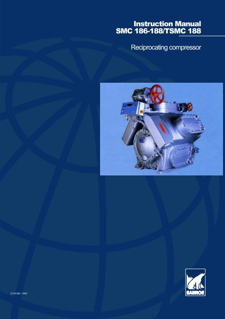
<strong>Instruction</strong> <strong>Manual</strong><br />
<strong>SMC</strong> <strong>186</strong>-<strong>188</strong>/T<strong>SMC</strong> <strong>188</strong><br />
Reciprocating compressor<br />
0178-900 - ENG
04.02<br />
<strong>Instruction</strong> manual for<br />
<strong>SMC</strong> <strong>186</strong>-<strong>188</strong> Mk2 and T<strong>SMC</strong> <strong>188</strong> Mk2<br />
The <strong>SMC</strong>/T<strong>SMC</strong>-type piston compressor can<br />
be fitted with a range of equipment, depending<br />
on the function and requirements it is<br />
calledontomeet.<br />
Some of these variants are discussed in this<br />
instruction manual, even if they are not featured<br />
on your particular unit.<br />
The variants featured on the unit are marked<br />
withan’x’ in the following diagram, with the<br />
serial number stated below.<br />
Compressor type<br />
Designation<br />
Serial number<br />
Refrigerant<br />
Control<br />
R717 ❑ R22 ❏ _____ ❏<br />
UNISAB II<br />
Analogous<br />
Compressor Water cooling (top- and side covers)<br />
cooling<br />
Oil cooling (Water-cooled side covers)<br />
Coupling<br />
Drive type<br />
V-belt<br />
Explosion-proof execution<br />
Equipment for parallel operation<br />
Oil separator<br />
0178-900-EN 1
Preface<br />
The aim of this instruction manual is to provide<br />
the operators with a thorough knowledge<br />
of the compressor and the unit and at<br />
the same time provide information about:<br />
S<br />
S<br />
S<br />
the function and maintenance of the individual<br />
components;<br />
service schedules;<br />
procedure for dismantling and reassembling<br />
of the compressor.<br />
this instruction manual to ensure a safe, reliable<br />
and efficient operation of the product as<br />
Sabroe Refrigeration is unable to provide a<br />
guarantee against damage of the product occurring<br />
during the warranty period as a<br />
result of incorrect operation.<br />
Dismantling and assembly of compressors<br />
and components should only be carried out<br />
by authorized personnel to prevent<br />
accidents.<br />
This instruction manual draws attention to<br />
typical errors which may occur during operations.<br />
The manual states causes of error and<br />
explains what should be done to rectify the<br />
errors in question.<br />
It is imperative that the operators familiarize<br />
themselves thoroughly with the contents of<br />
The contents of this instruction manual must<br />
not be copied or passed on to any unauthorized<br />
person without Sabroe<br />
Refrigeration’s permission.<br />
Sabroe Refrigeration’s General Conditions<br />
for the Supply of Components and Spare<br />
Parts will apply.<br />
0171-500-EN 00.07<br />
In the space below you can enter the name and address of your local Sabroe<br />
Refrigeration Representative:<br />
2 0178-900-EN
Table of Contents<br />
<strong>Instruction</strong> manual for <strong>SMC</strong> <strong>186</strong>-<strong>188</strong> Mk2 and T<strong>SMC</strong> <strong>188</strong> Mk2 ..................... 1<br />
Preface ..................................................................... 2<br />
Table of Contents ............................................................ 3<br />
First Aid for Accidents with Ammonia ........................................... 6<br />
First Aid for Accidents with HFC/HCFC .......................................... 7<br />
Protecting the Operator as well as the Environment ............................... 8<br />
Description of compressors <strong>SMC</strong> <strong>186</strong>-<strong>188</strong> Mk2, T<strong>SMC</strong> <strong>188</strong> Mk2 .................... 11<br />
Handling of the compressor, areas of application, safety equipment etc. ............. 13<br />
Vibration Data for Compressors - All Compressor Types ........................... 16<br />
Sound data for reciprocating and screw compressor units -- all types of compressors .. 17<br />
Compressor data for reciprocating compressor ................................... 21<br />
Operating limits ............................................................ 21<br />
General operating instructions for CMO/TCMO, <strong>SMC</strong>/T<strong>SMC</strong> piston compressors ..... 26<br />
Starting up compressor and plant ............................................. 26<br />
Stopping and starting-up compressor during a short period of standstill ............ 27<br />
Stopping plant for brief periods (until 2-3 days) ................................. 27<br />
Stopping plant for lengthy periods (more than 2-3 days) ......................... 28<br />
Automatic plants ........................................................... 28<br />
Pressure testing refrigeration plant ........................................... 28<br />
Pumping down refrigeration plant ............................................. 29<br />
Operating log .............................................................. 31<br />
Servicing the reciprocating compressor ......................................... 32<br />
Pressure drop test .......................................................... 32<br />
Removing refrigerant from compressor ........................................ 33<br />
Lubricating oil ................................................................ 37<br />
Lubricating oil requirements ................................................. 37<br />
General rules for use of lubricating oil in refrigeration compressors ................ 37<br />
<strong>Instruction</strong>s for choosing lubricating oil for refrigeration compressors .............. 37<br />
Charging refrigeration compressor with lubricating oil ........................... 37<br />
Changing oil in refrigeration compressor ....................................... 38<br />
Charging the compressor with oil ............................................... 40<br />
Assessing the oil ........................................................... 40<br />
Visual assessment ......................................................... 41<br />
Analytical evaluation ........................................................ 41<br />
Procedure ................................................................. 41<br />
The analysis ............................................................... 42<br />
Expected discharge gas temperatures .......................................... 45<br />
Servicing the Refrigeration Plant ............................................... 46<br />
Maintenance of piston compressor ............................................. 48<br />
0178-900-EN 3
1. If the compressor is operational ............................................ 48<br />
2. If the compressor is inoperative ............................................ 48<br />
Top covers ................................................................ 49<br />
Mounting top and water covers ............................................... 50<br />
Discharge valve ............................................................ 51<br />
Cylinder lining with suction valve ............................................. 53<br />
Connecting rod ............................................................ 54<br />
1. Slide bearing ............................................................ 55<br />
2. Needle bearing .......................................................... 56<br />
Dismanting of needle bearing ................................................ 58<br />
Piston .................................................................... 58<br />
Shaft seal ................................................................. 60<br />
Crankshaft ................................................................ 61<br />
Main bearings ............................................................. 63<br />
Compressor lubricating system ............................................... 64<br />
Oil pump .................................................................. 65<br />
Oil pressure valve .......................................................... 67<br />
By-pass valve pos. 24 ...................................................... 68<br />
Oil filter ................................................................... 70<br />
Suction filters .............................................................. 71<br />
Stop valves ................................................................ 72<br />
Unloaded start and capacity regulation on <strong>SMC</strong> and T<strong>SMC</strong> 100 and 180 compressors 74<br />
Description of unloader mechanism and capacity regulation ...................... 74<br />
Pilot solenoid valves ........................................................ 76<br />
Schematic outlines ......................................................... 77<br />
Standard unloaded start and capacity regulation ................................ 78<br />
Schematic drawings 1 ...................................................... 78<br />
Totally unloaded start and capacity regulation .................................. 79<br />
Schematic drawings 2 ...................................................... 79<br />
Relief cylinders ............................................................. 80<br />
Heating rods, pos. 30 ......................................................... 81<br />
Stop valves pos. 23 and 42 .................................................... 82<br />
Monitoring cylinder lining insertion .............................................. 83<br />
1. Checking clearance volume ............................................... 83<br />
2. Checking lifting reserve ................................................... 84<br />
Pressure gauges ............................................................. 86<br />
Undersize Bearing Diameters for Crankshaft ..................................... 88<br />
Sundry clearances and check dimensions ....................................... 89<br />
Torque moments for screws and bolts ........................................... 90<br />
Refrigeration Plant Maintenance ............................................... 92<br />
Operational reliability ....................................................... 92<br />
Pumping down the refrigeration plant ......................................... 92<br />
Dismantling plant ........................................................... 92<br />
Tightness testing and pump-down of refrigeration plant .......................... 93<br />
Trouble-shooting on the Piston Compressor Plant ................................ 94<br />
Selecting Lubricating Oil for SABROE Compressors .............................. 106<br />
Data Sheet for Listed Sabroe Oils .............................................. 112<br />
4 0178-900-EN
List of Major Oil Companies ................................................. 135<br />
Alignment of unit, AMR coupling ................................................ 136<br />
Boring of motor flange for AMR coupling ........................................ 142<br />
V-belt drive for piston compressor types (T)CMO and (T)<strong>SMC</strong> ...................... 143<br />
Oil Separator OVUR for <strong>SMC</strong>/T<strong>SMC</strong> 100 HPC - <strong>SMC</strong>/T<strong>SMC</strong> 180 ................... 145<br />
Connections on <strong>SMC</strong> <strong>186</strong> - <strong>188</strong> ................................................ 149<br />
Connections on T<strong>SMC</strong> <strong>188</strong> ................................................... 150<br />
Oil return in parallel operation for reciprocating compressors ....................... 151<br />
Water-cooling of reciprocating compressors ..................................... 154<br />
Cooling of the intermediate gas on TCMO and T<strong>SMC</strong> 100 and 180 ................. 162<br />
Ordering Spare Parts ......................................................... 167<br />
Spare parts sets for compressors and units ...................................... 168<br />
Compressor block .......................................................... 168<br />
Spare part set for Basic Unit ................................................. 168<br />
Complete set of gaskets for <strong>SMC</strong>/T<strong>SMC</strong> ................................ 0661-640<br />
Spare parts for <strong>SMC</strong>/T<strong>SMC</strong> ............................................ 0661-610<br />
Tools for compressor <strong>SMC</strong>/T<strong>SMC</strong> ...................................... 0661-630<br />
Spare Parts drawing ............................................. 0661-606 / 0661-607<br />
Spare Parts drawing (in detail) ......................................... 0661-608<br />
Piping diagram ...................................................... order specific<br />
Wiring diagram ...................................................... order specific<br />
Dimension sketch .................................................... order specific<br />
Cooling water diagram ................................................ order specific<br />
Foundation .......................................................... order specific<br />
Placing of vibration dampers ........................................... order specific<br />
0178-900-EN 5
First Aid for Accidents with Ammonia<br />
(Chemical formula: NH 3 - refrigerant no.: R717)<br />
Warning!<br />
Noplantcaneverbesaidtobetoosafesafety<br />
is a way of life.<br />
General<br />
Ammonia is not a cumulative poison. It has a<br />
distinctive, pungent odour that even at very<br />
low, harmless concentrations is detectable by<br />
most persons.<br />
Since ammonia is self-alarming, it serves as<br />
its own warning agent. This means that no<br />
person will remain voluntarily in concentrations<br />
which are hazardous. Since ammonia is<br />
lighter than air, adequate ventilation is the<br />
best means of preventing an accumulation.<br />
Experience has shown that ammonia is<br />
extremely hard to ignite and under normal<br />
conditions a very stable compound. At extremely<br />
high, though limited concentrations,<br />
ammonia can form ignitable mixtures with air<br />
and oxygen and should be treated with respect.<br />
Basic Rules for First Aid<br />
1. Call a doctor immediately.<br />
2. Be prepared: Keep an irrigation bottle<br />
available containing a sterile isotonic<br />
(0.9%) NaCl-solution (salt water).<br />
3. A shower bath or water tank should be<br />
available near all bulk installations with<br />
ammonia.<br />
4. When applying first aid, the persons<br />
assisting should be duly protected to avoid<br />
further injuries.<br />
Inhalation<br />
1. Move affected personnel into fresh air<br />
immediately and loosen clothing restricting<br />
breathing.<br />
2. Call a doctor/ambulance with oxygen<br />
equipment immediately.<br />
3. Keep the patient still and warmly wrapped<br />
in blankets.<br />
4. If mouth and throat are burnt (freeze or<br />
acid burn), let the conscious patient drink<br />
water, taking small mouthfuls.<br />
5. If the patient is conscious and the mouth<br />
is not burnt, feed the patient with<br />
sweetened tea or coffee (never feed an<br />
unconscious person).<br />
6. Oxygen may be administered, but only<br />
when authorised by a doctor.<br />
7. If the patient’s breathing stops, apply<br />
artificial respiration.<br />
Eye injuries from liquid splashes or concentrated<br />
vapour<br />
1. Force the eyelids open and rinse eyes<br />
immediately for at least 30 minutes with<br />
the salt water solution just mentioned.<br />
2. Call a doctor immediately.<br />
Skin burns from liquid splashes or concentrated<br />
vapour<br />
1. Wash immediately with large quantities of<br />
water and continue for at least 15 minutes,<br />
removing contaminated clothing carefully<br />
while washing.<br />
2. Call a doctor immediately.<br />
3. After washing, apply wet compresses<br />
(wetted with a sterile isotonic (0.9%) NaClsolution<br />
(salt water) to affected areas until<br />
medical advice is available.<br />
0170-008-EN 96.01<br />
6 0178-900-EN
First Aid for Accidents with HFC/HCFC<br />
Refrigerant no.: R134a - R505A - R507 - R22, etc.<br />
Warning!<br />
Noplantcaneverbesaidtobetoosafesafety<br />
is a way of life.<br />
General<br />
HFC/HCFC form colourless and invisible<br />
gasses which are heavier than air and smell<br />
faintly of chloroform at high concentrations.<br />
They are non-toxic, non-inflammable, nonexplosive<br />
and non-corrosive under normal<br />
operating conditions. When heated to above<br />
approx. 300°C, they break down into toxic,<br />
acid gas components, which are strongly<br />
irritating and aggressive to nose, eyes and<br />
skin and generally corrosive. Besides the<br />
obvious risk of unnoticeable, heavy gases<br />
displacing the atmospheric oxygen,<br />
inhalation of larger concentrations may have<br />
an accumulating, anaesthetic effect which<br />
may not be immediately apparent. 24 hours<br />
medical observation is therefore recommended.<br />
Basic Rules for First Aid<br />
1. When moving affected persons from lowlying<br />
or poorly ventilated rooms where<br />
high gas concentrations are suspected,<br />
the rescuer must be wearing a lifeline and<br />
be under continuous observation from an<br />
assistant outside the room.<br />
2. Adrenaline or similar heart stimuli must<br />
not be used.<br />
Inhalation<br />
1. Move affected persons into fresh air<br />
immediately. Keep the patients still and<br />
warm and loosen clothing restricting<br />
breathing.<br />
2. If the patient is unconscious, call a doctor/<br />
ambulance with oxygen equipment<br />
immediately.<br />
3. Give artificial respiration until a doctor<br />
authorizes other treatment.<br />
Eye Injuries<br />
1. Force the eyelids open and rinse with a<br />
sterile isotonic (0.9%) NaCl-solution (salt<br />
water) or pure running water continuously<br />
for 30 minutes.<br />
2. Contact a doctor or get the patient to a<br />
hospital immediately for medical advice.<br />
Skin Injuries - Freeze Burns<br />
1. Wash immediately with large quantities of<br />
lukewarm water to reheat the skin.<br />
Continue for at least 15 minutes, removing<br />
contaminated clothing carefully while<br />
washing.<br />
2. Treat exactly like heat burns and seek<br />
medical advice.<br />
3. Avoid direct contact with contaminated oil/<br />
refrigerant mixtures from electrically<br />
burnt-out hermetic compressors.<br />
0178-900-EN 7
Protecting the Operator as well as the Environment<br />
Warning!<br />
Noplantcaneverbesaidtobetoosafesafety<br />
is a way of life.<br />
Increasing industrialisation threatens our environment.<br />
It is therefore absolutely imperative<br />
to protect nature against pollution.<br />
To this end, many countries have passed legislation<br />
in an effort to reduce pollution and<br />
preserve the environment. This legislation<br />
applies to all fields of industry, including refrigeration,<br />
and must be complied with.<br />
Be especially careful with the following substances:<br />
S<br />
S<br />
S<br />
refrigerants<br />
cooling media (brine, etc)<br />
lubricating oils.<br />
Refrigerants usually have a natural boiling<br />
point considerably below 0°C. This means<br />
that liquid refrigerants can be extremely<br />
harmful if they come into contact with skin or<br />
eyes.<br />
High concentrations of refrigerant vapours<br />
are suffocating when they displace air. If high<br />
concentrations of refrigerant vapours are inhaled,<br />
they will attack the human nervous<br />
system.<br />
When halogenated gasses come into contact<br />
with open flame or hot surfaces (over approx.<br />
300°C), they will decompose to produce poisonous<br />
chemicals, which have a very pungent<br />
odour, thus warning the personnel of<br />
their presence.<br />
At high concentrations R717 causes respiratory<br />
problems, and when ammonia vapour<br />
and air mix 15 to 28 vol. %, the combination<br />
is explosive and can be ignited by an electric<br />
spark or open flame.<br />
Oil vapour in the ammonia vapour increases<br />
this risk significantly as the point of ignition<br />
falls below that of the mixture ratio stated.<br />
Usually the strong smell of ammonia will<br />
warn the personnel before the concentrations<br />
become dangerous.<br />
The following table shows the values for the<br />
max. permissible refrigerant content in air<br />
measured in volume %. Certain countries<br />
may, however, have an official limit which differs<br />
from those stated.<br />
0170-009-EN 01.10<br />
Halogenated refrigerants<br />
HFC<br />
HCFC<br />
Ammonia<br />
R134a R404A R407C R410A R507 R22<br />
R717<br />
TWA<br />
Time weighted average<br />
during a week<br />
Unit<br />
vol.% 0.1 0.1 0.1 0.1 0.1 0.1 0.005<br />
Warning smell vol.% 0.2 0.002<br />
8 0178-900-EN
Furthermore, it can be said about<br />
refrigerants:<br />
HFC/HCFC<br />
S If released to the atmosphere, halogenated<br />
refrigerants of the type HFC/HCFC<br />
(e.g. R22) will contribute to the depletion<br />
of the ozone layer in the stratosphere. The<br />
ozone layer protects the earth from the<br />
ultraviolet rays of the sun. Refrigerants of<br />
the types HFC/HCFC are greenhouse<br />
gases which contribute to an intensification<br />
of the greenhouse effect. They must,<br />
therefore, never be released to the atmosphere.<br />
Use a separate compressor to<br />
draw the refrigerant into the plant condenser/receiver<br />
or into separate refrigerant<br />
cylinders.<br />
S<br />
Most halogenated refrigerants are miscible<br />
with oil. Oil drained from a refrigeration<br />
plant will often contain significant<br />
amounts of refrigerant. Therefore, reduce<br />
the pressure in the vessel or compressor<br />
as much as possible before draining the<br />
oil.<br />
Ammonia<br />
S<br />
S<br />
S<br />
Ammonia is easily absorbed by water:<br />
At 15°C 1 litre of water can absorb approx.<br />
0.5 kg liquid ammonia (or approx. 700<br />
litres ammonia vapour).<br />
Even small amounts of ammonia in water<br />
(2-5 mg per litre) are enough to wreak<br />
havoc with marine life if allowed to pollute<br />
waterways and lakes.<br />
As ammonia is alkaline, it will damage<br />
plant life if released to the atmosphere in<br />
large quantities.<br />
CO 2<br />
S CO 2 is a gas which can be discharged into<br />
the open without causing any harm to the<br />
environment. It must be ensured, however,<br />
that the eyes and skin of people<br />
working in the proximity of the plant are<br />
not exposed to the discharged CO 2 as it<br />
can be extremely cold.<br />
S<br />
S<br />
CO 2 is a harmless gas, but in closed<br />
rooms it can displace the oxygen and thus<br />
cause suffocation.<br />
CO 2 is odourless.<br />
Refrigerant evacuated from a refrigerant<br />
plant must be charged into refrigerant cylinders<br />
intended for this specific refrigerant.<br />
If the refrigerant is not to be reused, return it<br />
to the supplier or to an authorized incineration<br />
plant.<br />
Halogenated refrigerants must never be<br />
mixed. Nor must R717 ever be mixed with<br />
halogenated refrigerants.<br />
Purging a Refrigeration Plant<br />
If it is necessary to purge airfromarefrigeration<br />
plant, make sure to observe the following:<br />
S<br />
S<br />
S<br />
Refrigerants must not be released to the<br />
atmosphere.<br />
When purging an R717 plant, use an approved<br />
air purger. The purged air must<br />
pass through an open container of water<br />
for any remaining R717 to be absorbed.<br />
The water mixture must be sent to an authorized<br />
incineration plant.<br />
Halogenated refrigerants cannot be absorbed<br />
by water. An approved air purger<br />
must be fitted to the plant. This must be<br />
checked regularly using a leak detector.<br />
0178-900-EN 9
Cooling Media<br />
Salt solutions (brines) of calcium chloride<br />
(CaCl 2 ) or sodium chloride (NaCl) are often<br />
used.<br />
In recent years alcohol, glycol and halogenated<br />
compounds have been used in the brine<br />
production.<br />
In general, all brines must be considered as<br />
being harmful to nature and they must be<br />
used with caution. Be very careful when<br />
charging or purging a refrigeration plant.<br />
Never empty brines down a sewer or into<br />
the environment.<br />
The brine must be collected in suitable containers<br />
clearly marked with the contents and<br />
sent to an approved incineration plant.<br />
Lubricating Oils<br />
Warning!<br />
When charging oil, avoid that your skin<br />
comes into direct contact with the oil. Direct<br />
contact with oils may in the long run develop<br />
allergy attacks. Use therefore always protective<br />
equipment - goggles and gloves - when<br />
charging oil.<br />
Refrigeration compressors are lubricated by<br />
one of the following oil types depending on<br />
the refrigerant, plant type and operating conditions.<br />
-- Mineral oil<br />
-- Semi-synthetic oil<br />
-- Alkyl benzene-based synthetic oil<br />
-- Polyalphaolefine-based synthetic oil<br />
-- Glycol-based synthetic oil.<br />
-- Ester oil<br />
When changing the oil in the compressor or<br />
draining oil from the vessels of the refrigeration<br />
plant, always collect the used oil in containers<br />
marked “waste oil” and send them to<br />
an approved incineration plant.<br />
NOTE<br />
This instruction only provides general information. The owner of the refrigeration plant is<br />
responsible for ensuring that all codes, regulations and industry standards are complied<br />
with.<br />
10 0178-900-EN
Description of compressors<br />
<strong>SMC</strong> <strong>186</strong>-<strong>188</strong> Mk2, T<strong>SMC</strong> <strong>188</strong> Mk2<br />
0178-902-EN 96.12<br />
The <strong>SMC</strong> 180 and T<strong>SMC</strong> 180 compressors<br />
have 180 mm diameter pistons, as indicated<br />
by the first digits in the type designation and<br />
with a stroke length of 140 mm. The number<br />
of cylinders in the compressor block is indicated<br />
by the following digit, where, for example,<br />
<strong>SMC</strong> <strong>188</strong> is an 8-cylinder compressor.<br />
<strong>SMC</strong> 180 is a one-stage compressor which<br />
compresses the gas in one single stage.<br />
Type<br />
Shop no<br />
Max. speed<br />
Swept volume<br />
Working pressure<br />
Test pressure<br />
SABROE<br />
AARHUS<br />
Refrigerant<br />
Year<br />
DENMARK<br />
r.p.m.<br />
m 3 /h<br />
bar<br />
bar<br />
In the T<strong>SMC</strong> <strong>188</strong> two-stage compressor, the<br />
gas is compressed in two stages at a ratio of<br />
1:3 between the number of high- and lowpressure<br />
cylinders. Thus, a T<strong>SMC</strong> <strong>188</strong> has 2<br />
high-pressure cylinders and 6 low-pressure<br />
cylinders.<br />
The type can be determined by the nameplate,<br />
located on the end face of the compressor,<br />
facing away from the coupling/belt<br />
drive. The following illustration shows a<br />
SABROE name-plate.<br />
T0177093_2<br />
Similarly, the name-plate indicates the compressor’s<br />
serial number, which is also stamped<br />
into the compressor housing near the suction<br />
chambers.<br />
Whenever contacting SABROE about the<br />
compressor, its serial number should be<br />
stated.<br />
The pistons operate in cylinder linings, which<br />
are inserted in the frame with two cylinders<br />
under each top cover. The suction valves, of<br />
0178-900-EN 11
the ring-plate type, are mounted at the top of<br />
the cylinder linings. The pressure valves form<br />
the top of the cylinder linings and are kept in<br />
position by a powerful safety spring. The<br />
safety spring allows the discharge valve unit<br />
to rise, providing a greater throughflow aperture<br />
in the event of liquid strokes in the cylinder.<br />
This prevents any overloading of the<br />
connecting rod bearings.<br />
The crankshaft is supported in slide bearings<br />
able to assimilate both radial and axial<br />
forces. The oil pressure for the bearings and<br />
the capacity regulating system is supplied<br />
from the gearwheel oil pump incorporated in<br />
the compressor.<br />
At the axle end, the crankshaft is fitted with a<br />
balanced slide-ringtype seal consisting of a<br />
cast iron ring with an O-ring which rotates<br />
with the crankshaft, and a stationary<br />
spring-loaded carbon ring.<br />
All compressors can be capacity-regulated<br />
by connecting or disconnecting the cylinders<br />
in pairs. The following diagram shows the<br />
capacity stages at which the compressors<br />
can operate.<br />
Capacity regulation is controlled by means of<br />
solenoid valves mounted on the compressor.<br />
25% 33% 50% 67% 75% 100%<br />
<strong>SMC</strong> <strong>186</strong> x x x<br />
<strong>SMC</strong> <strong>188</strong> x x x x<br />
T<strong>SMC</strong> <strong>188</strong> x x x<br />
12 0178-900-EN
Handling of the compressor, areas of application,<br />
safety equipment etc.<br />
0170-119-EN 97.12<br />
Direction of rotation<br />
In order to reduce the noise level from the<br />
electric motors these are often executed with<br />
specially shaped fan wings, thus determining<br />
a particular direction of rotation.<br />
In case you yourself order a motor you<br />
should take into consideration whether the<br />
motor is intended for direct coupling or for<br />
belt drive of the compressor.<br />
The direction of rotation of the compressor<br />
for compressors CMO-TCMO and <strong>SMC</strong>-<br />
T<strong>SMC</strong> is indicated by an arrow cast into the<br />
compressor cover, near the shaft seal.<br />
On the BFO compressors the direction of<br />
rotation is not indicated by an arrow but is<br />
standard as illustrated by the following<br />
sketch:<br />
clearly marked with red paint. The weight of<br />
the unit is stated on the package as well as in<br />
the shipping documents.<br />
During transportation and handling care<br />
should be taken not to damage any of the<br />
components, pipe or wiring connections.<br />
Areas of application of the reciprocating<br />
compressors<br />
Compressor types:<br />
BFO 3-4-5<br />
CMO-TCMO,<br />
<strong>SMC</strong> 100-T<strong>SMC</strong> 100 Mk3, S, L, E<br />
<strong>SMC</strong> 180-T<strong>SMC</strong> 180,<br />
HPO-HPC<br />
In view of preventing an unintended application<br />
of the compressor, which could cause<br />
injuries to the operating staff or lead to technical<br />
damage, the compressors may only be<br />
applied for the following purposes:<br />
Seen towards shaft end<br />
Handling of compressor and unit<br />
For lifting of the compressor the large models<br />
are equipped with a threaded hole for mounting<br />
of the lifting eye. As to the weight of the<br />
compressor, see table on compressor data.<br />
Note:<br />
The compressor block alone may be lifted<br />
in the lifting eye. The same applies to the<br />
motor.<br />
The unit is lifted by catching the lifting eyes<br />
welded onto the unit frame. These have been<br />
The compressor may ONLY be used:<br />
S As a refrigeration compressor with a number<br />
of revolutions and with operating limits<br />
as indicated in this manual or according to<br />
a written agreement with SABROE.<br />
S With the following refrigerants:<br />
R717 -- R22 1 -- R134a 1 -- R404A 1 --<br />
R410A 1 -- R507 1 -- R600 1 -- R600A 1 --<br />
R290 1 -- LPG 1<br />
1 ) Exempted are the following compressors:<br />
<strong>SMC</strong>-T<strong>SMC</strong> 100 E (only R717)<br />
HPO and HPC (only R717 and R410A))<br />
All other types of gas may only be<br />
used following a written approval from<br />
SABROE.<br />
S<br />
As a heat pump:<br />
0178-900-EN 13
S<br />
-- BFO 3-4-5<br />
CMO - TCMO and <strong>SMC</strong> - T<strong>SMC</strong> may<br />
be used with a max. discharge pressure<br />
of 25 bar.<br />
-- HPO--HPCmaybeusedwithamax.<br />
discharge pressure of 40 bar.<br />
In an explosion-prone environment, provided<br />
the compressor is fitted with approved<br />
explosion-proof equipment.<br />
The compressor must NOT be used:<br />
S For evacuating the refrigeration plant of air<br />
and moisture,<br />
S For putting the refrigeration plant under air<br />
pressure in view of a pressure testing,<br />
S As an air compressor.<br />
Emergency device<br />
The compressor control system must be<br />
equipped with an emergency device.<br />
In case the compressor is delivered with a<br />
SABROE-control system this emergency device<br />
is found as an integrated part of the control.<br />
The emergency device must be executed in<br />
a way to make it stay in its stopped position,<br />
following a stop instruction, until it is deliberately<br />
set back again. It must not be possible<br />
to block the emergency stop without a stop<br />
instruction being released.<br />
S<br />
manual handle, to which there is free access.<br />
It must be able to stop any dangerous situation,<br />
which may occur, as quickly as<br />
possible without this leading to any further<br />
danger.<br />
Combustion motors<br />
If combustion motors are installed in rooms<br />
containing refrigeration machinery or rooms<br />
where there are pipes and components containing<br />
refrigerant, you must make sure that<br />
the combustion air for the motor is derived<br />
from an area in which there is no refrigerant<br />
gas, in case of leakage.<br />
Failure to do so will involve a risk of the lubricating<br />
oil from the combustion motor mixing<br />
with the refrigerant; at worst, this may give<br />
rise to corrosion and damage the motor.<br />
Explosion-proof electrical execution<br />
If the compressor is delivered in an explosion-proof<br />
electrical execution, this is stated<br />
in the table on page 1 of this instruction<br />
manual.<br />
Likewise, the compressor will, besides the<br />
SABROE name plate, be equipped with an<br />
Ex-name plate like the one illustrated below.<br />
It should only be possible to set back the<br />
emergency device by a deliberate act, and<br />
this set back must not cause the compressor<br />
to start operating. It should only make it possibletorestartit.<br />
Other demands to the emergency device:<br />
S It must be possible to operate it by means<br />
of an easily recognizable and visible<br />
T2516273_0<br />
14 0178-900-EN
The temperature of tangible surfaces<br />
When a compressor is working, the surfaces<br />
that are in contact with the warm discharge<br />
gas also get warm. However, the temperature<br />
depends on which refrigerants and under<br />
which operating conditions the compressor<br />
is working. Often, it exceeds 70°C which for<br />
metal surfaces may cause your skin to be<br />
burnt even at a light touch.<br />
close to the warning signs during operation<br />
are so hot that your skin may be burnt from 1<br />
second’s touch or longer.<br />
Consequently, the compressors will be equipped<br />
with yellow warning signs informing<br />
you that pipes, vessels and machine parts<br />
0178-900-EN 15
Vibration Data for Compressors - All Compressor Types<br />
Vibration data for Sabroe Refrigeration’s<br />
Sabroe reciprocating compressors complies<br />
with: the ISO 10816, standard, Part 6,<br />
Annex A, group 4, AB, which fixes max permissible<br />
operating vibrations at 17.8 mm/s.<br />
Vibration data for Sabroe Refrigeration’s<br />
Sabroe screw compressors complies with:<br />
ISO 10816 standard, part 1, Annex B,<br />
Class III, C, which fixes max permissible<br />
operating vibrations at 11.2 mm/s.<br />
The measurements are made as illustrated in<br />
the figure below (points A-D).<br />
0170-115-EN 01.01<br />
Pay attention to the following, however:<br />
S<br />
S<br />
S<br />
Motors comply with EN 60034-14 (CEI/<br />
IEC 34-14) Class N.<br />
When placing the unit on vibration<br />
dampers supplied by Sabroe Refrigeration<br />
(additional), the vibrations against the<br />
foundation are reduced by:<br />
-- 85-95% for screw compressor units<br />
-- 80% for recip. compressor units<br />
However, a higher vibration level may occur<br />
if:<br />
-- motor and compressor have not been<br />
aligned as described in the <strong>Instruction</strong><br />
<strong>Manual</strong>.<br />
-- the compressor runs at a wrong V i ratio.<br />
This applies to screw compressors.<br />
-- the piping connections have been<br />
executed in a way that makes them force<br />
pull or push powers on the compressor<br />
unit or transfer vibrations to the unit<br />
caused by natural vibrations or connected<br />
machinery.<br />
-- the vibration dampers have not been<br />
fitted or loaded correctly as indicated in<br />
the foundation drawing accompanying<br />
with the order.<br />
16 0178-900-EN
Sound data for compressor units<br />
0170-114--EN 02.07<br />
In the following tables the noise data of the<br />
compressors is stated in:<br />
-- A-weighted sound power level LW<br />
(Sound Power Level)<br />
-- A-weighted sound pressure level LP<br />
(Sound Pressure level)<br />
The values for LW constitute an average of a<br />
large number of measurings on various units.<br />
The measurings have been carried out in accordance<br />
with ISO 9614-2.<br />
The values are further stated as average<br />
sound pressure in a free field above a reflecting<br />
plane at a distance of 1 meter from<br />
a fictional frame around the unit. See fig. 1.<br />
Normally, the immediate sound pressure<br />
lies between the LW and LP values and can<br />
be calculated provided that the acoustic data<br />
of the machine room is known.<br />
For screw compressors the average values<br />
are indicated in the tables for the following<br />
components.<br />
Dimension tolerances are :<br />
1 ±3 dB for SAB, SV and FV screw compressors<br />
±5 dB for SAB 283 L/E and SAB 355 L<br />
screw compressors<br />
As to the reciprocating compressors the<br />
values are stated for the compressor block<br />
only. The dimensional values are stated for<br />
100% capacity.<br />
Fig. 1.1<br />
Fictional frame<br />
Dimensional plane<br />
1 meter<br />
1 meter<br />
Reflecting plane<br />
0178-900-EN 17
Note the following, however:<br />
S<br />
S<br />
at part load or if the compressor works<br />
with a wrongly set V i the sound level can<br />
sometimes be a little higher than the one<br />
indicated in the tables.<br />
additional equipment such as heat exchangers,<br />
pipes, valves etc. as well as<br />
another motor type can increase the noise<br />
level in the machine room.<br />
S<br />
S<br />
stated -- e.g. near the compressor and<br />
motor.<br />
the acoustics is another factor that can<br />
change the sound level in a room. Please<br />
note that the sound conditions of the site<br />
have not been included in the stated<br />
dimensional values.<br />
by contacting Sabroe Refrigeration you<br />
can have sound data calculated for other<br />
operating conditions.<br />
S<br />
as already mentioned, the stated sound<br />
pressures are only average values above<br />
a fictional frame around the noise source.<br />
Thus, it is sometimes possible to measure<br />
higher values in local areas than the ones<br />
Tables for Noise Data<br />
The following tables show the operating<br />
conditions of the compressor during the<br />
noise measurements as well as the applied<br />
refrigerant.<br />
18 0178-900-EN
RECIPROCATING COMPRESSORS<br />
One-stage<br />
Evaporating temperature = --15°C<br />
Condensing temperature = +35°C<br />
Refrigerant = R22/R717<br />
Number of revolutions = 1450 o/min.<br />
Compressor block LW LP<br />
CMO 24 84 69<br />
CMO 26 86 71<br />
CMO 28 87 72<br />
<strong>SMC</strong> 104 S 95 79<br />
<strong>SMC</strong> 106 S 96 80<br />
<strong>SMC</strong> 108 S 97 81<br />
<strong>SMC</strong> 112 S 99 82<br />
<strong>SMC</strong> 116 S 100 83<br />
<strong>SMC</strong> 104 L 96 80<br />
<strong>SMC</strong> 106 L 97 81<br />
<strong>SMC</strong> 108 L 98 82<br />
<strong>SMC</strong> 112 L 100 83<br />
<strong>SMC</strong> 116 L 101 84<br />
<strong>SMC</strong> 104 E 96 80<br />
<strong>SMC</strong> 106 E 97 81<br />
<strong>SMC</strong> 108 E 98 82<br />
<strong>SMC</strong> 112 E 100 83<br />
<strong>SMC</strong> 116 E 101 84<br />
Evaporating temperature = --15°C<br />
Condensing temperature = +35°C<br />
Refrigerant = R22/R717<br />
Number of revolutions = 900 o/min.<br />
Compressor block<br />
LW<br />
LP<br />
<strong>SMC</strong> <strong>186</strong> 101 83<br />
<strong>SMC</strong> <strong>188</strong> 102 84<br />
Two-strage<br />
Evaporating temperature = --35°C<br />
Condensing temperature = +35°C<br />
Refrigerant = R22/R717<br />
Number of revolutions = 1450 o/min.<br />
Compressor block<br />
LW<br />
LP<br />
TCMO 28 81 66<br />
T<strong>SMC</strong> 108 S 95 79<br />
T<strong>SMC</strong> 116 S 97 81<br />
T<strong>SMC</strong> 108 L 96 80<br />
T<strong>SMC</strong> 116 L 98 82<br />
T<strong>SMC</strong> 108 E 96 80<br />
T<strong>SMC</strong> 116 E 98 82<br />
Evaporating temperature = --35°C<br />
Condensing temperature = +35°C<br />
Refrigerant = R22/R717<br />
Number of revolutions = 900 o/min.<br />
Compressor block<br />
LW<br />
LP<br />
T<strong>SMC</strong> <strong>188</strong> 100 82<br />
Heat pump<br />
Evaporating temperature = +20°C<br />
Condensing temperature = +70°C<br />
Refrigerant = R22/R717<br />
Number of revolutions = 1450 o/min.<br />
Compressor block<br />
LW<br />
LP<br />
HPO 24 91 76<br />
HPO 26 93 78<br />
HPO 28 94 79<br />
HPC 104 97 81<br />
HPC 106 98 82<br />
HPC 108 99 84<br />
0178-900-EN 19
SCREW COMPRESSORS<br />
Evaporating temperature = --15°C<br />
Condensing temperature = +35°C<br />
Refrigerant = R22/R717<br />
Number of revolutions = 2950 o/min.<br />
*Number of revolutions = 6000 o/min.<br />
Compressor block LW LP<br />
SAB 110 SM 98 81<br />
SAB 110 SF 98 81<br />
SAB 110 LM 98 81<br />
SAB 110 LF 98 81<br />
Evaporating temperature = --35°C<br />
Condensing temperature = --5°C<br />
Refrigerant = R22/R717<br />
Number of revolutions = 2950 o/min.<br />
Compressor unit LW LP<br />
SAB 163 BM 106 88<br />
SAB 163 BF 110 92<br />
SAB 110 SM Mk2 - -<br />
SAB 110 SF Mk2 - -<br />
SAB 110 LM Mk2 - -<br />
SAB 110 LF Mk2 - -<br />
SAB 110 LR* Mk2 - -<br />
SAB 110 SR* Mk2 - -<br />
SAB 128 M Mk3 100 82<br />
SAB 128 F Mk3 104 86<br />
SAB 128 R* Mk3 104 86<br />
SAB 128 M Mk4 - -<br />
SAB 128 F Mk4 - -<br />
SAB 128 R* Mk4 - -<br />
SAB 163 M Mk3 103 85<br />
SAB 163 F Mk 3 105 87<br />
SAB 163 R* Mk 3 105 87<br />
SAB 163 M Mk4 - -<br />
SAB 163 F Mk4 - -<br />
SAB 163 R* Mk4 - -<br />
SAB 202 SM 105 86<br />
SAB 202 SF 106 87<br />
SAB 202 LM 105 86<br />
SAB 202 LF 107 88<br />
SAB 283 L 107 87<br />
SAB 283 E 108 88<br />
SAB 355 L 109 89<br />
SAB 81 103 84<br />
SAB 83 104 85<br />
SAB 85 105 86<br />
SV 87 106 86<br />
SV 89 108 87<br />
20 0178-900-EN
Compressor data for reciprocating compressor<br />
CMO 4, CMO 24-28, TCMO 28, <strong>SMC</strong> 104-116,<br />
T<strong>SMC</strong> 108-116, <strong>SMC</strong> <strong>186</strong>-<strong>188</strong>, T<strong>SMC</strong> <strong>188</strong><br />
Operating limits<br />
SABROE prescribes operating limits within which the compressor and any additional equipment<br />
must operate. These limits for R717 and R22 are shown in the following tables, together with<br />
the main data for the compressor.<br />
0171-496-EN 02.01<br />
Compressor<br />
type<br />
Number of<br />
cylinders<br />
Bore<br />
mm<br />
Stroke<br />
mm<br />
Max/min<br />
Speed<br />
RPM<br />
Swept<br />
volume<br />
max RPM*<br />
m 3 /h<br />
Weight<br />
(max.)<br />
compr. block<br />
kg<br />
CMO 4 4 65 65 1800/900 93,2 200<br />
CMO 24 4 70 70 1800/900 116 340<br />
CMO 26 6 70 70 1800/900 175 380<br />
CMO 28 8 70 70 1800/900 233 410<br />
TCMO 28 2+6 70 70 1800/900 175 410<br />
<strong>SMC</strong> 104S 4 100 80 1500/700 226 580<br />
<strong>SMC</strong> 106S 6 100 80 1500/700 339 675<br />
<strong>SMC</strong> 108S 8 100 80 1500/700 452 740<br />
<strong>SMC</strong> 112S 12 100 80 1500/700 679 1250<br />
<strong>SMC</strong> 116S 16 100 80 1500/700 905 1350<br />
T<strong>SMC</strong> 108S 2+6 ♦ 100 80 1500/700 339 775<br />
T<strong>SMC</strong> 116S 4+12 ♦ 100 80 1500/700 679 1400<br />
<strong>SMC</strong> 104L 4 100 100 1500/700 283 580<br />
<strong>SMC</strong> 106L 6 100 100 1500/700 424 675<br />
<strong>SMC</strong> 108L 8 100 100 1500/700 565 740<br />
<strong>SMC</strong> 112L 12 100 100 1500/700 848 1250<br />
<strong>SMC</strong> 116L 16 100 100 1500/700 1131 1350<br />
T<strong>SMC</strong> 108L 2+6♦ 100 100 1500/700 424 775<br />
T<strong>SMC</strong> 116L 4+12♦ 100 100 1500/700 757 1400<br />
<strong>SMC</strong> 104E 4 100 120 1500/700 339 600<br />
<strong>SMC</strong> 106E 6 100 120 1500/700 509 700<br />
<strong>SMC</strong> 108E 8 100 120 1500/700 679 770<br />
<strong>SMC</strong> 112E 12 100 120 1500/700 1018 1300<br />
<strong>SMC</strong> 116E 16 100 120 1500/700 1357 1400<br />
T<strong>SMC</strong> 108E 2+6♦ 100 120 1500/700 509 800<br />
T<strong>SMC</strong> 116E 4+12♦ 100 120 1500/700 1018 1450<br />
<strong>SMC</strong> <strong>186</strong> 6 180 140 1000/450 1283 2560<br />
<strong>SMC</strong> <strong>188</strong> 8 180 140 1000/450 1710 2840<br />
T<strong>SMC</strong> <strong>188</strong> 8 180 140 1000/450 1283 2900<br />
✶<br />
♦<br />
The maximum speed permitted can be lower than stated here depending on operating<br />
conditions and refrigerant; please see the following diagrams.<br />
Two - stage compressors (High Stage cylinders and Low Stage cylinders)<br />
0178-900-EN 21
T245400_0/2 Condensing temperature<br />
°F<br />
158<br />
140<br />
122<br />
104<br />
86<br />
68<br />
50<br />
32<br />
14<br />
-- 4<br />
-- 22<br />
-- 40<br />
TC<br />
°C<br />
70<br />
60<br />
50<br />
40<br />
30<br />
20<br />
10<br />
0<br />
-- 10<br />
-- 20<br />
-- 30<br />
-- 40<br />
-- 70<br />
-- 94<br />
1<br />
4<br />
2<br />
3<br />
-- 60 -- 50 -- 40 -- 30 -- 20 -- 10 0 10 20 30 40 °C<br />
--76 --58 --40 --22 --4 14 32 50 68 86 104 °F<br />
Evaporating temperature<br />
R717<br />
Operating limits<br />
single stage<br />
compressors<br />
CMO<br />
<strong>SMC</strong> 100 S-L<br />
<strong>SMC</strong> 180<br />
TE<br />
Area rpm Cooling<br />
Type<br />
CMO 20<br />
<strong>SMC</strong> 100<br />
S-L<br />
<strong>SMC</strong> 180<br />
1--2<br />
3-4<br />
1-2<br />
3<br />
4 1200<br />
1 750<br />
2-3-4 1000*<br />
max min Booster Single and HP-stage compr.<br />
Air-cooled top- and side covers # - or water-cooled<br />
1800 900<br />
Water-cooled Thermopump or water-cooled<br />
1500<br />
700<br />
Air-cooled top- and side covers # - or water-cooled<br />
Water-cooled<br />
Thermopump or water-cooled<br />
450 Water-cooled<br />
# Including refrigerant-cooled oil cooler * 840 to 920 not allowed<br />
Thermopump:<br />
Top- and side covers are cooled<br />
by refrigerant injection.<br />
Oil cooling included in the system<br />
Water-cooled:<br />
Top- and side covers.<br />
Oil cooling included in the system.<br />
NB:<br />
At part load the discharge gas temp. must not exceed 150°C/302°F<br />
22 0178-900-EN
Condensing temperature<br />
TC<br />
°F °C<br />
158 70<br />
140 60<br />
122 50<br />
104 40<br />
86 30<br />
68 20<br />
50 10<br />
32 0<br />
14 -- 10<br />
2<br />
1<br />
R717<br />
Operating limits<br />
two-stage<br />
compressors<br />
TCMO<br />
T<strong>SMC</strong> 100 S-L-E<br />
T<strong>SMC</strong> 180<br />
-- 4<br />
-- 20<br />
-- 22<br />
-- 30<br />
0177128_0 VIEW 3,1<br />
-- 40<br />
-- 40<br />
-- 70<br />
-- 94<br />
-- 60 -- 50 -- 40 -- 30 -- 20 -- 10 0 10 20 30 40 °C<br />
--76 --58 --40 --22 --4 14 32 50 68 86 104 °F<br />
Evaporating temperature<br />
TE<br />
Type Area rpm Cooling Note<br />
max min top and side<br />
TCMO 1--2 1800 900 Thermopump or water-cooled<br />
T<strong>SMC</strong> 100<br />
1-2 1500 700 Thermopump or water-cooled 1)<br />
S-L-E<br />
1 750<br />
T<strong>SMC</strong> 180<br />
450 Water-cooled 1)<br />
2 1000<br />
Oil cooling is always necessary.<br />
Thermopump:<br />
Only the HP Stage top covers are cooled<br />
by a thermo pump<br />
Oil cooling included in the system<br />
Water-cooled:<br />
Top- and side covers.<br />
Oil cooling included in the system.<br />
Part-load operation:<br />
1) Depending on the operating conditions<br />
and the presure on the compressor a bypass<br />
system may be required.<br />
See section: By-pass system for two-stage compressors.<br />
0178-900-EN 23
Condensing temperature<br />
TC<br />
°F °C<br />
158 70<br />
140 60<br />
122 50<br />
104 40<br />
86 30<br />
68 20<br />
50 10<br />
32 0<br />
14 -- 10<br />
4<br />
3<br />
2<br />
1<br />
R22<br />
Operating limits<br />
single stage<br />
compressors<br />
CMO<br />
<strong>SMC</strong> 100 S-L<br />
<strong>SMC</strong> 180<br />
-- 4<br />
-- 22<br />
-- 20<br />
-- 30<br />
0177128_0 VIEW 4,1<br />
-- 40<br />
-- 40<br />
-- 70<br />
-- 94<br />
-- 60 -- 50 -- 40 -- 30 -- 20 -- 10 0 10 20 30 40 °C<br />
--76 --58 --40 --22 --4 14 32 50 68 86 104°F<br />
Evaporating temperature<br />
Type Area rpm Oil-cooling Note<br />
max min required 1)<br />
1<br />
no<br />
1500<br />
2<br />
no<br />
CMO<br />
900<br />
3<br />
At less than 50% capacity<br />
1800<br />
4<br />
yes<br />
1 1000 no<br />
2 1200<br />
no<br />
<strong>SMC</strong> 100 S<br />
700<br />
3 1500<br />
At less than 50% capacity<br />
4 1200 yes<br />
1 Not applicable<br />
2 1000 no<br />
<strong>SMC</strong> 100 L<br />
3 1200 700 At less than 50% capacity<br />
4 1000 yes<br />
1-2 Not applicable<br />
<strong>SMC</strong> 180 3<br />
At less than 50% capacity<br />
750 450<br />
4<br />
yes<br />
TE<br />
Top covers: Air-cooled design only.<br />
1) When oil cooling is required there is a free<br />
choice between A and B - However, for<br />
<strong>SMC</strong> 180 only A may be selected.<br />
A: Water-cooled side covers<br />
B: Built-in refrigerant-cooled oil cooler with<br />
thermostatic expansion valve.<br />
24 0178-900-EN
Condensing temperature<br />
TC<br />
°F °C<br />
158 70<br />
140 60<br />
122 50<br />
104 40<br />
86 30<br />
68 20<br />
50 10<br />
32 0<br />
14 -- 10<br />
3<br />
4<br />
2<br />
1<br />
R22<br />
Operating limits<br />
two-stage<br />
compressors<br />
TCMO<br />
T<strong>SMC</strong> 100 S-L<br />
T<strong>SMC</strong> 180<br />
-- 4<br />
-- 20<br />
-- 22<br />
-- 30<br />
0177128_0 VIEW 5,1<br />
-- 40<br />
-- 40<br />
-- 70<br />
-- 94<br />
-- 60 -- 50 -- 40 -- 30 -- 20 -- 10 0 10 20 30 40 °C<br />
--76 --58 --40 --22 --4 14 32 50 68 86 104 °F<br />
Evaporating temperature<br />
TE<br />
Type Area rpm Oil-cooling Note<br />
max min required 1)<br />
TCMO<br />
1-2 1500<br />
3-4 1800<br />
900 no<br />
1 1000<br />
T<strong>SMC</strong><br />
2-3 1200 100 S<br />
4 1500<br />
700 yes 2)<br />
1 Not applicable<br />
T<strong>SMC</strong><br />
2 1000<br />
100 L<br />
700 yes 2)<br />
3-4 1200<br />
<strong>SMC</strong> 180<br />
1-2 Not applicable<br />
3-4 750 450 yes 2)<br />
Top covers: Air-cooled design only.<br />
1) When oil cooling is required there is a free<br />
choice between A and B - However, for<br />
<strong>SMC</strong> 180 only A may be selected.<br />
A: Water-cooled side covers<br />
B: Built-in refrigerant-cooled oil cooler with<br />
thermostatic expansion valve.<br />
Part-load operation:<br />
2) Depending on the operating conditions<br />
and the presure on the compressor a bypass<br />
system may be required.<br />
See section: By-pass system for two-stage compressors.<br />
0178-900-EN 25
General operating instructions for<br />
CMO/TCMO, <strong>SMC</strong>/T<strong>SMC</strong> reciprocating compressors<br />
Starting up compressor and plant<br />
S<br />
Before the initial start-up of the compressor<br />
following a lengthy stand-still period of<br />
several months, the compressor must be<br />
prelubricated. Hereby, the bearings are<br />
lubricated and the oil system filled up<br />
with oil before the compressor is set running.<br />
Carry out the prelubrication by connecting<br />
the oil pump to the prelubricating<br />
valve which in the more recent <strong>SMC</strong>-<br />
T<strong>SMC</strong>-HPC compressors is connected to<br />
the shaft seal housing pos. 6A and on the<br />
CMO-TCMO-HPO to the cover pos. 86H<br />
or 87K. As prelubricating pump we recommend<br />
SABROE’s hand-operated oil pump<br />
part no 3141-155, which is mounted as<br />
showninfig.1.<br />
Fig. 1<br />
To compressor<br />
Cap<br />
valve for prelubrication<br />
Gasket<br />
Optional hand ---<br />
operated oilpump<br />
For pre-lubrication use a clean new refrigerant<br />
machine oil of the same type as the<br />
one found in the compressor, and pump as<br />
follows:<br />
Compressor<br />
type<br />
CMO<br />
TCMO<br />
HPO<br />
<strong>SMC</strong> 104<br />
106-108<br />
T<strong>SMC</strong> 108<br />
HPC<br />
S<br />
S<br />
<strong>SMC</strong> 112-116<br />
T<strong>SMC</strong> 116<br />
<strong>SMC</strong> <strong>186</strong>-<strong>188</strong><br />
T<strong>SMC</strong> <strong>188</strong><br />
Pump strokes w.<br />
SABROEs<br />
hand-operated<br />
oil pump<br />
appr. 25<br />
appr. 35<br />
appr. 45<br />
appr. 50<br />
Estimated<br />
oil quantity<br />
Liters<br />
2.5<br />
3.5<br />
4.5<br />
5.0<br />
The heating rod in the crankcase must be<br />
energized at least 6-8 hours before starting<br />
up the compressor in order to boil any<br />
refrigerant out of the compressor oil. At<br />
the same time, the suction check valve<br />
must be open.<br />
Check oil level in crankcase. The oil level<br />
must always be visible in the oil sight<br />
glass. See section: Charging the compressor<br />
with oil.<br />
0171-461-EN 96.06<br />
T0177131_0 V15<br />
S<br />
S<br />
S<br />
S<br />
Start condenser cooling, brine pumps,<br />
fans at air coolers as well as any compressor<br />
cooling device.<br />
Check correct setting of safety automatics<br />
on compressor.<br />
Open discharge stop valve at compressor.<br />
Set capacity regulator to minimum capacity.<br />
26 0178-900-EN
S<br />
S<br />
S<br />
S<br />
S<br />
S<br />
S<br />
In order to avoid excessive pressure reduction<br />
in the compressor on start--up, the<br />
suction stop valve must be opened a few<br />
turns, as there is otherwise a risk of oil<br />
foaming in the crankcase.<br />
Open all other stop valves except for the<br />
main valve in the liquid line and possible<br />
by-pass valves serving other purposes.<br />
Check that the time relay 3K13 keeps the<br />
solenoid valve in the oil return line closed<br />
for 20-30 mins. after start-up of the compressor.<br />
Start compressor motor and check suction<br />
and oil pressures.<br />
Carefully continue opening suction stop<br />
valve to its full open position.<br />
Open main valve in liquid line.<br />
If the oil in the crankcase foams, or knocking<br />
noises are heard from the compressor<br />
because droplets of liquid are being fed in<br />
with the suction gas, throttle suction stop<br />
valve immediately.<br />
Stopping and starting-up compressor<br />
during a short period of<br />
standstill<br />
Before stopping the compressor, its capacity<br />
must be reduced to the lowest capacity stage<br />
for a few minutes, before it stops.<br />
During short periods of standstill, it is not<br />
necessary to shut off the suction stop valve<br />
and the discharge stop valve. The heating<br />
rod must be energized.<br />
If the compressor is cooled by means of cooling<br />
water, the water flow must always be<br />
stopped during periods of standstill.<br />
This is normally done by means of a solenoid<br />
valveinthewaterinletlinetothecompressor.<br />
Connect the solenoid valve to the start/stop<br />
relay of the compressor motor.<br />
Compressor start-up must always take place<br />
at the lowest capacity stage, after which capacity<br />
is increased stepwise at suitable intervals,<br />
in order to avoid that a sudden excessive<br />
pressure reduction in the evaporation<br />
system causes liquid hammering in the compressor<br />
and oil foaming in the crankcase.<br />
S<br />
S<br />
The compressor is now operating.<br />
Increase capacity stepwise, allowing the<br />
compressor to adjust to new conditions<br />
before switching to next stage.<br />
Check carefully whether oil is foaming and<br />
whether oil pressure is correct.<br />
Check whether oil return from oil separator<br />
is working. (Pay attention to any clogging<br />
of filter and nozzle.)<br />
The pipe should normally be warm.<br />
Stopping plant for brief periods<br />
(until 2-3 days)<br />
S<br />
S<br />
S<br />
Shut off liquid supply to evaporators for a<br />
few minutes before stopping the plant.<br />
Stop compressor and shut off suction and<br />
discharge stop valves. Close valve in oil<br />
return.<br />
Stop condenser cooling, pumps, fans and<br />
any compressor cooling.<br />
S<br />
Do not leave plant for first 15 minutes after<br />
start-up and never before it has stabilized.<br />
S<br />
Cut off power supply to both master and<br />
control currents.<br />
0178-900-EN 27
Stopping plant for lengthy periods<br />
(more than 2-3 days)<br />
S<br />
S<br />
S<br />
S<br />
S<br />
S<br />
Shut off main valve after receiver and<br />
pump down evaporators. If necessary, adjust<br />
low-pressure cut-out on unit to a lower<br />
pressure during evacuation.<br />
Allow temperature in evaporators to rise,<br />
then repeat evacuation.<br />
When suction pressure has been reduced<br />
to slightly over atmospheric, stop compressor.<br />
Shut off suction and discharge<br />
stop valves and close off stop valve in oil<br />
return.<br />
Shut off condenser cooling. If there is a<br />
risk of freezing, draw off coolant.<br />
Cut off power supply to master and control<br />
currents.<br />
Inspect receiver, condenser and pressure<br />
vessels as well as piping connections and<br />
apparatus for leakage.<br />
Automatic plants<br />
S<br />
S<br />
S<br />
Refrigeration plant should normally be put<br />
into operation as described in the Start-up<br />
section.Once started, switch over to automatic<br />
operation.<br />
Special instructions for automatic plant in<br />
question should be followed to the letter.<br />
The following should be checked daily,<br />
even on automatic plants:<br />
-- correct oil charging,<br />
-- automatic oil return,<br />
-- correct oil pressure,<br />
-- suction and condenser pressures,<br />
discharge pipe temperature,<br />
-- correct setting of safety automatics.<br />
Pressure testing refrigeration plant<br />
Before charging the plant with refrigerant, it<br />
must be pressure tested and pumped down.<br />
Pressure test the plant with one of the following:<br />
S<br />
S<br />
S<br />
dry air - pressurized cylinders containing<br />
dry atmospheric air may be used - but<br />
never oxygen cylinders;<br />
air compressor for high pressure;<br />
nitrogen.<br />
Important<br />
The plant compressors must not be<br />
used to pressurize the plant.<br />
Water or other fluids must not be used<br />
for pressure testing.<br />
If nitrogen is used, it is important to place a<br />
reducing valve with a pressure gauge between<br />
the nitrogen cylinder and the plant.<br />
During pressure testing, it is important to ensure<br />
that pressure transducers and other<br />
control equipment are not exposed to the<br />
testing pressure. The compressor stop<br />
valves must also be closed during pressure<br />
testing.<br />
Plant safety valves must normally be blanked<br />
off during pressure testing, as their opening<br />
pressure is lower than the testing pressure.<br />
Important<br />
During this pressure testing, no person<br />
should be allowed to be present in<br />
rooms housing plant parts or in the vicinity<br />
of the plant outside the rooms.<br />
28 0178-900-EN
S<br />
S<br />
S<br />
S<br />
The entire unit must be pressure tested in<br />
accordance with the local regulations for<br />
pressure testing.<br />
The test pressure must never exceed the<br />
disign pressure.<br />
If it is required that the compressor should<br />
be pressure tested together with the unit<br />
or with the plant, the testing pressure must<br />
not exceed:<br />
For reciprocating compressors:<br />
HP side: 24 bar<br />
LP side: 17.5 bar<br />
Please observe that manometers, pressure<br />
controls, pressure transmitters and<br />
other control equipment are not exposed<br />
to testing pressure.<br />
atmospheric air and moisture. Evacuation<br />
must be carried out on all types of refrigeration<br />
plant, regardless of the type of refrigerant<br />
with which the plant is to be charged.<br />
Observe that HCFC and HFC refrigerants<br />
mix only minimally with water, and it is therefore<br />
necessary to effect evacuation of such<br />
systems with particular care.<br />
The boiling point of a fluid is defined as the<br />
temperature at which the steam pressure<br />
equals atmospheric pressure. For water, the<br />
boiling point is 100°C. Lowering the pressure<br />
also lowers the boiling point of the water.<br />
The table sets out the boiling point of water<br />
at very low pressures:<br />
S<br />
Afterwards, reduce pressure to 10 bar for<br />
a period of 24 hours - as an initial tightness<br />
test - as a tightly sealed plant will<br />
maintain this pressure throughout the period.<br />
During the tightness test, it is permitted to<br />
enter the room and approach the plant.<br />
S<br />
By way of a second tightness test, examine<br />
all welds, flange joints etc. for leakage<br />
by applying soapy water, while maintaining<br />
the 10 bar pressure.<br />
When pressure testing, compile a pressure<br />
test report containing the following:<br />
S<br />
S<br />
S<br />
date of pressure testing,<br />
person carrying out the test,<br />
comments.<br />
Pumping down refrigeration plant<br />
Following pressure testing, the refrigeration<br />
plant must be evacuated in order to eliminate<br />
Boiling point of<br />
water °C<br />
5<br />
10<br />
15<br />
20<br />
At pressure<br />
mm HG<br />
6,63<br />
9,14<br />
12,73<br />
17,80<br />
For evacuation, use a vacuum pump which<br />
bleeds the plant of air and steam.<br />
The vacuum pump must be able to lower the<br />
pressure to approx. 0.1 mm Hg (mercury column)<br />
and must be fitted with a gas ballast<br />
valve. This valve should be used wherever<br />
possible to prevent water vapours condensing<br />
in the vacuum pump.<br />
Important<br />
Never use the refrigeration compressor<br />
to evacuate the plant.<br />
0178-900-EN 29
For a satisfactorily performed evacuation, the<br />
final pressure must be lower than 5 mm Hg.<br />
Attention is drawn to the fact that there may<br />
be a risk of any water left in the refrigeration<br />
plant freezing if ambient temperatures are<br />
lower than 10°C. In such instances, it will be<br />
necessary to supply heat to the component<br />
surroundings, as ice evaporates with difficulty.<br />
It is recommended to carry out evacuation as<br />
follows:<br />
S<br />
Evacuatetoapressurelowerthan5mm<br />
Hg.<br />
S<br />
S<br />
S<br />
Blow dry air or nitrogen into system to a<br />
pressure corresponding to atmospheric.<br />
Never use OXYGEN cylinders.<br />
Repeat evacuation to reduce pressure to<br />
less than 5 mm Hg.<br />
Shut the vacuum pump off from refrigeration<br />
plant and check that the pressure<br />
does not rise for the next couple of hours.<br />
If the system still contains water, this will<br />
evaporate and cause the pressure to rise,<br />
thereby indicating unsatisfactory evacuation<br />
and necessitating a repetition of the<br />
procedure.<br />
30 0178-900-EN
Operating log<br />
In order to keep tabs on the operating state<br />
of the refrigeration plant, it is recommended<br />
that an operating log be kept.<br />
This operating log should be kept at regular<br />
intervals, thus providing important information<br />
about the cause of any undesired<br />
changes in the operating state.<br />
(See following page)<br />
Observation Measuring point Measurement unit<br />
Time<br />
Suction pressure<br />
Discharge pressure<br />
Oil pressure<br />
• Compressor pressure gauge<br />
• UNISAB II Control<br />
• Compressor pressure gauge<br />
• UNISAB II Control<br />
• Compressor pressure gauge<br />
• UNISAB II Control<br />
Date and time<br />
°C or bar<br />
°C or bar<br />
bar<br />
Oil temperature<br />
Suction gas temp.<br />
Discharge gas temp.<br />
Oil level in<br />
compressor<br />
Recharding of oil on<br />
compressor<br />
Compressor motor’s<br />
consumption in amps.<br />
• UNISAB II Control<br />
• Thermometer in suction pipe<br />
immediately<br />
before compressor<br />
• UNISAB II Control<br />
• Thermometer in discharge pipe<br />
immediately after compressor but<br />
before oil separator<br />
• UNISAB II Control<br />
• Oil level sight glass<br />
in compressor<br />
• See section on oil<br />
charging<br />
• Electrical panel<br />
• UNISAB II (additional)<br />
°C<br />
°C<br />
°C<br />
Must be visible in oil<br />
sight glass<br />
Number of litres<br />
Amps<br />
At the same time, attention should be paid to the following:<br />
(tick these off in the log, if you wish)<br />
S whether the compressor’s cooling system is functioning correctly,<br />
S whether any unusual noise is coming from the compressor,<br />
S whether there are unusual vibrations in the compressor.<br />
0178-900-EN 31
Servicing the reciprocating compressor<br />
Reciprocating compressors CMO/TCMO, <strong>SMC</strong>/T<strong>SMC</strong><br />
100 and <strong>SMC</strong>/T<strong>SMC</strong> 180<br />
In order to ensure problem-free operation, it<br />
is advisable to carry out regular servicing to<br />
the refrigeration plant. In this section,<br />
SABROE indicates some periodic services<br />
fixed on the basis of the number of operating<br />
hours from the first start-up or after over<br />
hand of the compressor.<br />
The servicing schedules also depend on the<br />
speed of the compressor. If the compressor<br />
is running at less than 1200 rpm, SABROE<br />
permits extended service intervals. However,<br />
the compressor must always operate within<br />
the speed recommended by SABROE. See<br />
Description of compressor. Providing the<br />
compressor operates within the specified<br />
pressures and temperatures and the prescribed<br />
periodic services are performed, the<br />
compressor will have a long and efficient service<br />
life.<br />
Using the pressure drop test, it is possible to<br />
check the internal tightness of the compressor<br />
from discharge to suction side. The pressure<br />
drop test is performed with the compressor<br />
at standstill, as described below:<br />
S<br />
S<br />
S<br />
S<br />
Immediately after stopping compressor,<br />
read off pressure on discharge and suction<br />
side of compressor.<br />
Close discharge stop valve quickly and,<br />
from moment of closure, time how long it<br />
takes for pressure to drop on high pressure<br />
side of compressor. Normally, the<br />
pressure drop should not be more than 3<br />
bar over a period of 5 minutes or so.<br />
If the pressure falls more quickly, this is<br />
due to internal leakage, which may occur:<br />
where pressure valve ring plates are in<br />
bad contact with their seats (Pos. 20C<br />
against Pos. 20A and 19H);<br />
with defective seal Pos. 19T; ( not CMO)<br />
0171-462-EN 99.05<br />
S<br />
The following must therefore be checked<br />
daily:<br />
Operating pressure,<br />
Operating temperatures,<br />
Oil level and pressure,<br />
Abnormal noise and vibrations.<br />
The actual operating conditions should be<br />
entered in an operating log daily. See the Operating<br />
log section.<br />
Pressure drop test:<br />
S with defective seal Pos. 19K;<br />
S<br />
S<br />
because cylinder lining and top cover<br />
have been tightened without long mounting<br />
stopper having been fitted. Cylinder<br />
lining is thus resting on rocker arms, Pos.<br />
15A; (not CMO).<br />
on safety valve, because valve cone does<br />
not fit tightly against seat, or outer O-ring<br />
Pos. 24B or inner O-ring Pos. 24C is defective.<br />
(See Safety valve section.)<br />
During pressure drop testing, pay attention to<br />
any piping connections to the discharge side<br />
of the compressor, which may have an influence<br />
on the test result.<br />
32 0178-900-EN
Removing refrigerant from<br />
compressor<br />
Before the compressor can be dismantled,<br />
the refrigerant must be removed from the<br />
compressor, which can be done in the following<br />
ways:<br />
1. Run compressor at lowest capacity stage<br />
and throttle suction stop valve slowly until<br />
completely closed.<br />
2. The compressor will then stop on the low<br />
pressure cut-out. This can be adjusted to<br />
stop compressor at a pressure lower than<br />
normal.<br />
3. Close discharge stop valve and other piping<br />
connections to compressor.<br />
4. On HFC and HCFC compressors, remove<br />
remaining refrigerant gas using a pumpdown<br />
compressor connected to purge valve<br />
Pos. 42.<br />
S<br />
42<br />
Evacuating pump<br />
R22<br />
On the R717 compressor, adopt the following<br />
method:<br />
42<br />
Water<br />
R717<br />
Connect the purge valve Pos. 42 to a sealed,<br />
empty vessel which in turn is connected to an<br />
open tank containing water.<br />
The water will absorb the refrigerant, which<br />
can then be dispatched for proper destruction.<br />
The moment the pressure is equalized,<br />
the valve must be reclosed in order to prevent<br />
water being sucked back into the compressor.<br />
Note:<br />
The following instructions apply to the<br />
compressor only. Servicing of the refrigeration<br />
plant is described in a separate<br />
section. Service the compressor motor according<br />
to your own instructions. For the<br />
various scheduled services, SABROE can<br />
supply ready-made spare-part sets, which<br />
it would be an advantage to have before<br />
carrying out the scheduled service.<br />
In the event that the compressor cannot operate,<br />
start evacuation as described under pt.<br />
3, and remember also to close the suction<br />
stop valve.<br />
0178-900-EN 33
No.<br />
1<br />
2<br />
3<br />
Scheduled services<br />
Operating<br />
hours<br />
< 1200 rpm<br />
Operating<br />
hours<br />
> 1200 rpm<br />
75 50<br />
300 200<br />
7500 5000<br />
Activity<br />
1.1 Remove and discard filter bag in suction filter.<br />
Clean suction filter. Following major repair work or<br />
in event of severe soiling of filter bag, it is recommended<br />
that a new filter bag be fitted for another<br />
period of 50 operating hours.<br />
1.2 Check tension of driving belts.<br />
2.1 Check or change oil. When changing oil, change oil<br />
filter cartridge, too. See following section:<br />
Assessing the oil.<br />
2.2 Clean suction filter.<br />
2.3 Check that following function correctly:<br />
Solenoid valves<br />
Compressor cooling<br />
Thermopump<br />
Safety automatics<br />
Heating rod<br />
V-belt drive.<br />
2.4 Retighten external piping connections.<br />
2.5 Check oil return system from oil separator.<br />
2.6 Retighten coupling.<br />
3.1 Check or change oil. When changing oil, change<br />
oil filter cartridge, too. See following section:<br />
Assessing the oil.<br />
3.2 Clean suction filter.<br />
3.3 Check that following function correctly:<br />
Solenoid valves<br />
Compressor cooling<br />
Thermopump<br />
Safety automaitcs<br />
Heating rod<br />
V-belt drive<br />
Oil return system from oil separator.<br />
3.4 For heat pump operation, inspect:<br />
Valve seats<br />
Cylinder linings<br />
Pistons, gudgeon pins and gudgeon pin bearings<br />
Piston and oil scraper rings.<br />
Change suction and discharge valve ring plates.<br />
3.5 Finish off with a pressure drop test.<br />
34 0178-900-EN
No.<br />
Operating<br />
hours<br />
< 1200 rpm<br />
Operating<br />
hours<br />
> 1200 rpm<br />
Activity<br />
4.1 Check or change oil. When changing oil, change oil<br />
filter cartridge, too. See following section: Assessing<br />
the oil.<br />
4.2 Clean suction filter.<br />
4<br />
15000 10000<br />
4.3 Check following:<br />
Solenoid valves<br />
Oil cooling system<br />
Water cooling system for any deposits and clogging<br />
Thermopump<br />
Safety automatics<br />
Heating rod<br />
V-belt drive<br />
Coupling and alignment<br />
Oil return system from oil separator<br />
Valve seats<br />
Cylinder linings<br />
Pistons, gudgeon pins and gudgeon pin bearings<br />
Piston and oil scraper rings<br />
Unloading mechanism<br />
Seal for tightness<br />
4.4 Change:<br />
Suction and discharge valve ring plates<br />
V-belts<br />
4.5 Finish off with a pressure drop test.<br />
5<br />
22500 15000<br />
5.1 Check V-belt drive<br />
5.2 For heat pump operation, inspect:<br />
Valve seats<br />
Cylinder linings<br />
Pistons, gudgeon pins and gudgeon pin bearings<br />
Piston and oil scraper rings.<br />
Change:<br />
Suction and discharge valve ring plates.<br />
0178-900-EN 35
No.<br />
Operating<br />
Hours<br />
< 1200 rpm<br />
Operating<br />
Hours<br />
> 1200 rpm<br />
Activity<br />
6.1 Change compressor oil,<br />
Change oil filter cartridge,<br />
Clean crankcase.<br />
6.2 Clean suction filter.<br />
6<br />
30000 20000<br />
6.3 Check following:<br />
Solenoid valves<br />
Oil cooling system<br />
Water cooling system for any deposits and clogging<br />
Thermopump<br />
Safety automatics<br />
Heating rod<br />
V-belt drive<br />
Coupling and alignment<br />
Valve seats<br />
Cylinder linings<br />
Pistons, gudgeon pins and gudgeon pin bearings<br />
Piston and oil scraper rings<br />
Unloading mechanism<br />
Seal for tightness<br />
Oil pump and drive<br />
Check valves.<br />
6.4 Change:<br />
Suction and discharge valve ring plates<br />
V-belts<br />
Half-sections of bearing for connecting rod<br />
(does not apply to CMO compressors)<br />
6.5 Finish off with a pressure drop test.<br />
7<br />
8<br />
9<br />
10<br />
37500 25000 As for service no. 5<br />
45000 30000 As for service no. 4<br />
52500 35000 As for service no. 3<br />
60000 40000 Major overhaul; contact SABROE Refrigeration<br />
Then repeat scheduled services from no. 3 inclusive.<br />
36 0178-900-EN
Lubricating oil<br />
Lubricating oil requirements<br />
Above all, the refrigerator oil must provide<br />
satisfactory lubrication of the compressor,<br />
even at the relatively high temperatures occurring<br />
during compression. It must be incapable<br />
of coking at such high temperatures<br />
and must not precipitate solid constituents<br />
such as paraffin or wax at the lowest occurring<br />
temperatures. The oil must not have any<br />
corrosive effect, whether alone or mixed with<br />
refrigerant. According to the oil companies<br />
the oils mentioned in the Oil Recommendation<br />
in this instruction manual comply with<br />
these conditions. See section on Choice of<br />
lubricating oils.<br />
General rules for use of lubricating<br />
oil in refrigeration compressors<br />
S<br />
S<br />
S<br />
Only fresh, clean refrigeration machine oil<br />
may be charged. Oil tapped from the<br />
evaporator system in an ammonia plant<br />
must not be reused in the compressor.<br />
Use grade of oil originally prescribed for<br />
compressor.<br />
As far as possible, avoid mixing different<br />
types of oil. Mixed oil is generally inferior<br />
to the two original oils. Mixing various<br />
types of oil may give rise to formation of<br />
sludge, which will lodge in valves and filters.<br />
S<br />
The refrigeration oil must be free of moisture,<br />
which may give rise to operating malfunctions<br />
and attacks of corrosion.<br />
The oil should therefore be purchased in containers<br />
corresponding to the quantity to be<br />
used for a single, or at most, two top-ups.<br />
The oil containers must be kept carefully<br />
sealed. If all the oil in a container is not used<br />
in one go, the container should be tightly<br />
sealed and stored in a warm place to prevent<br />
the absorption of moisture.<br />
Note:<br />
It is inadvisable to reuse oil which has<br />
been drawn from a compressor or plant.<br />
This oil will have absorbed moisture from<br />
the air and may cause operating problems.<br />
Always switch off the power to the heating<br />
rodbeforedrawingofftheoil.<br />
If, after reading the above, any doubt exists<br />
as to the type of oil which has been used on<br />
your compressor, you are recommended to<br />
contact SABROE, rather than risk charging<br />
with unsuitable oil.<br />
<strong>Instruction</strong>s for choosing<br />
lubricating oil for refrigeration<br />
compressors<br />
The instructions in Choice of lubricating oils<br />
offer more detailed guidelines for choosing<br />
the lubricating oil best suited to each individual<br />
case on the basis of the anticipated operating<br />
conditions.<br />
S<br />
If necessary to switch to another brand of<br />
oil, this must be done at the same time as<br />
completely changing the oil in the compressor<br />
and tapping off all oil from the refrigeration<br />
plant.<br />
Charging refrigeration compressor<br />
with lubricating oil<br />
Since all SABROE piston compressors are<br />
supplied with a special oil-charging valve on<br />
0178-900-EN 37
the crankcase, refrigeration oil may be<br />
topped up while the compressor is in operation.<br />
For this purpose, use a manual oil pump or<br />
adopt the following procedure:<br />
Note:<br />
When charging for the first time, use the<br />
oil pump; it goes without saying that the<br />
compressor must not be started unless<br />
already charged with oil.<br />
S<br />
S<br />
S<br />
Reduce pressure in crankcase, e.g. by<br />
throttling suction stop valve, until suction<br />
pressure gauge shows pressure slightly<br />
below atmospheric.<br />
Fill pipe connected to oil charging valve<br />
with refrigerator oil and insert free end of<br />
pipe down into a receptacle containing<br />
fresh refrigerator oil.<br />
Open oil charging valve carefully, thereby<br />
causing external air pressure to force oil<br />
into crankcase.<br />
therefore, it is necessary to refill with refrigeration<br />
oil after starting up for the first<br />
time and after charging with fresh refrigerant.<br />
For a while after the plant is started for the<br />
first time, keep an extra sharp eye on the oil<br />
level in the compressor, therefore.<br />
Changing oil in refrigeration compressor<br />
S<br />
S<br />
S<br />
Cut off power to heating rod.<br />
Close compressor stop valves and valve<br />
in oil return line from oil separator.<br />
Reduce pressure in compressor crankcase<br />
to slightly above atmospheric by<br />
throttling suction stop valve while compressor<br />
is running at its lowest capacity<br />
stage. Alternatively, raise to slightly above<br />
atmospheric pressure by stopping compressor<br />
and closing suction stop valve.<br />
Pressure in crankcase will then rise gradually.<br />
S<br />
Avoid getting air or other impurities<br />
sucked into compressor.<br />
Note:<br />
In order to achieve pressure below atmospheric,<br />
it will sometimes be necessary to<br />
reset the low-pressure cut-out so that the<br />
compressor can aspirate down to this<br />
pressure. Remember to reset the pressure<br />
cut-out to its normal setting after charging<br />
with oil.<br />
When in operation, the compressor may be<br />
refilled with oil using the manual oil pump.<br />
Note:<br />
Since halocarbon refrigerants such as<br />
R22 mix with refrigeration oils, there will<br />
always be a good portion of oil blended<br />
with the refrigerant in the plant. Often,<br />
S<br />
S<br />
S<br />
S<br />
S<br />
S<br />
S<br />
S<br />
Oil in the crankcase can then be forced<br />
out through drain valve Pos. 23 when<br />
compressor is at a standstill.<br />
Equalize pressure in compressor to atmospheric<br />
through purge valve pos. 42. See<br />
section on Environmental protection.<br />
Dismantle side covers.<br />
Replace oil filter cartridge with a new one.<br />
Clean crankcase thoroughly, wiping with a<br />
clean, dry linen cloth (not cotton waste).<br />
Reassemble side covers.<br />
Charge to correct level with fresh, clean<br />
refrigerator oil according to SABROE’s oil<br />
recommendations.<br />
Connect heating cartridge.<br />
38 0178-900-EN
S<br />
Connect vacuum pump to compressor and<br />
pump down to 5-7 mm Hg; close off connection.<br />
42 is open. See section on Environmental<br />
protection, however. When smelling R717,<br />
close purge valve.<br />
Then open suction stop valve a few turns,<br />
filling compressor with refrigerant gas. In<br />
the case of R717, it will suffice to blast the<br />
compressor through by carefully opening<br />
suction stop valve while purge valve Pos.<br />
S<br />
Open discharge stop valve and valve in oil<br />
return line; compressor is then ready for<br />
start-up as described in section<br />
General operating instructions.<br />
0178-900-EN 39
Charging the compressor with oil<br />
Compressor<br />
Type Size<br />
BFO<br />
CMO<br />
TCMO<br />
3<br />
4<br />
5<br />
24<br />
26<br />
28<br />
Volume of oil<br />
in crankcase<br />
Litres<br />
1,5<br />
4<br />
5<br />
14<br />
16<br />
18<br />
4 13<br />
The oil level must be checked with extreme<br />
care, particularly when starting and charging<br />
with refrigerant.<br />
The oil level must always be visible in the<br />
oil level sight glass. The below table illustrates,<br />
how many litres of oil a drop in the<br />
oil level of 10 mm is approximately equal<br />
to.<br />
<strong>SMC</strong> 100<br />
T<strong>SMC</strong> 100<br />
Mk 3<br />
S-L-E<br />
<strong>SMC</strong> 180<br />
T<strong>SMC</strong> 180<br />
104<br />
106<br />
108<br />
112<br />
116<br />
<strong>186</strong><br />
<strong>188</strong><br />
26<br />
28<br />
30<br />
47<br />
50<br />
80<br />
90<br />
T0177162_0<br />
The volume of oil stated in the table is the<br />
amount which must always be present in the<br />
crankcase.<br />
As a rule, the compressor should be charged<br />
with oil after the plant is started for the first<br />
time, as some of the oil -- especially on an<br />
HCFC installation -- will be absorbed by the<br />
refrigerant in the plant.<br />
The following determinants decide the total<br />
volume of oil a refrigeration plant should contain:<br />
S<br />
S<br />
S<br />
S<br />
type of refrigerant<br />
refrigerant charge (volume)<br />
size of plant<br />
temperature range in which refrigeration<br />
plant is to operate.<br />
Compressor<br />
type size<br />
CMO/<br />
TCMO<br />
<strong>SMC</strong> /<br />
T<strong>SMC</strong><br />
100<br />
S-L-E<br />
<strong>SMC</strong> /<br />
T<strong>SMC</strong><br />
180<br />
24<br />
26<br />
28<br />
104<br />
106<br />
108<br />
Assessing the oil<br />
10 millimeter<br />
difference in<br />
oil levels equals<br />
~1 litre of oil<br />
~2 litres of oil<br />
112<br />
116 ~6 litres of oil<br />
<strong>186</strong><br />
<strong>188</strong> ~6 litres of oil<br />
Refrigeration machine oil is a vital part of the<br />
compressor, as it not only lubricates and<br />
cools the movable parts of the compressor, it<br />
also prevents abrasive particles from entering<br />
the bearings.<br />
An analysis of the oil can give important information<br />
on how the compressor is running.<br />
40 0178-900-EN
We would, therefore, advise that the oil analyses<br />
be carried out at the intervals prescribed.<br />
An oil sample must be drawn off while the<br />
compressor is in operation, which gives a<br />
representative sample. Before taking the<br />
sample, clean the drain valve and tap a little<br />
oil off, to prevent any impurities which may<br />
have accumulated in the valve or the piping<br />
from mixing with the sample.<br />
As a special offer to our customers<br />
SABROE has developed an analytical concept,<br />
which is able to analyse all oil makes.<br />
This will mean a uniform reporting of the results.<br />
The analysis allows the following to be determined:<br />
S<br />
Whether or not the oil is still usable, if necessary<br />
after filtering.<br />
Visual assessment<br />
If you pour the sample into a clean, transparent<br />
glass bottle or a test-tube and hold it up<br />
to a clear light source, it will be easy to assess<br />
the quality. You can also compare the<br />
sample with the fresh oil of the same make<br />
and grade.<br />
An oil which you approve on the grounds of a<br />
visual assessment must:<br />
S<br />
S<br />
be clear and shiny<br />
not contain any visible particles<br />
S<br />
S<br />
Whether solid particles possibly present in<br />
the oil originate from the bearings or other<br />
components exposed to wear and tear in<br />
which case the compressor must be inspected.<br />
Each report will include the corresponding<br />
measuring results from theprevious3oil<br />
analyses. In this way you will be able to<br />
follow up on the state of both the oil and<br />
the compressor from one analysis to the<br />
next.<br />
S<br />
feel viscous, smooth and greasy when a<br />
drop is rubbed between two fingers.<br />
If you don’t feel that you can approve the oil<br />
by visual assessment, charge with new oil or<br />
send a sample to a laboratory for analysis.<br />
Warning<br />
If the oil sample is poured into a glass bottle,<br />
this must not be hermetically sealed until all<br />
the refrigerant in the oil sample has evaporated.<br />
Refrigerant in the oil may produce excess<br />
pressure in the bottle with subsequent<br />
risks of explosion. Never fill a bottle up completely.<br />
Do not send glass bottles through<br />
the postal service -- use purpose-made plastic<br />
bottles. Please see below.<br />
Procedure<br />
S<br />
S<br />
A form set with a plastic sampling bottle<br />
and a dispatching envelope can be requested<br />
from the local Sabroe Refrigeration<br />
representation.<br />
The oil sample must be drained from the<br />
cleaned oil drain valve into the sample<br />
bottle. Screw the lid loosely on and let the<br />
bottle stand for a few hours to enable refrigerant<br />
contained in the oil sample to<br />
evaporate before sending it to the laboratory.<br />
Analytical evaluation<br />
Naturally, the oil sample can be analysed by<br />
the oil company which supplies the oil.<br />
S<br />
Please follow the Sampling and Shipping<br />
<strong>Instruction</strong>s enclosed in the form set in<br />
which the addresses of the laboratory in<br />
Holland are also mentioned.<br />
0178-900-EN 41
The analysis<br />
The following table states some average<br />
values that can be applied in practice. However,<br />
you should be on the alert whenever<br />
the results of the analyses approach these<br />
values. In some cases the water content of<br />
100 ppm in HCFC plants may be too much<br />
and thus lead to Cu--plating in the shaft seal.<br />
Limiting values<br />
Parameter Unit Method Target<br />
Spec. Max. Min.<br />
Sabroe Oil PAO 68 Sabroe Oil AP 68 Sabroe Oil A 100<br />
Target<br />
Spec. Max. Min.<br />
Target<br />
Spec. Max. Min.<br />
Viscosity @ 40°C cSt ASTM D 445 66 76 53 64 74 51 100 115 80<br />
TAN *1) mg KOH/g ASTM D 664 0.03 0.2 -- 0.01 0.2 -- 0.05 0.2 --<br />
SAN * 2) mg KOH/g ASTM D 665 -- 0 -- -- 0 -- -- 0 --<br />
Water ppm Karl Fisher -- 100 -- -- 100 -- -- 100 --<br />
Appearance -- -- report report report<br />
Colour -- ASTM D<br />
1500<br />
Pentane Insolubles W% MM 490<br />
(5μm)<br />
report report report<br />
-- 0.05 -- 0.05 -- -- 0.05 --<br />
Oxidation abs/cm IR,1700-1720<br />
/cm<br />
Nitration abs/cm IR,1627-1637<br />
/cm<br />
Nitro Compounds abs/cm IR,1547-1557<br />
/cm<br />
-- 5 -- -- 5 -- -- 5 --<br />
-- 5 -- -- 5 -- -- 5 --<br />
-- 0.5 -- -- 0.5 -- -- 0.5 --<br />
Maximum values for metal content in the oil<br />
Lead ppm ICP -- 10 -- -- 10 -- -- 10 --<br />
Copper ppm ICP -- 10 -- -- 10 -- -- 10 --<br />
Silicium ppm ICP -- 25 -- -- 25 -- -- 25 --<br />
Iron ppm ICP -- 100 -- -- 100 -- -- 100 --<br />
Chromium ppm ICP -- 5 -- -- 5 -- -- 5 --<br />
Aluminium ppm ICP -- 10 -- -- 10 -- -- 10 --<br />
Tin ppm ICP -- 10 -- -- 10 -- -- 10 --<br />
1): TAN (Total Acid Number) is only reported for non-ammoniaapplications<br />
2): SAN (Strong Acid Number) is only reported for non-ammonia-applications<br />
42 0178-900-EN
A report is drawn up for every sample received.<br />
This report indicates:<br />
S<br />
S<br />
Whether the oil can still be used -- without<br />
taking any further action.<br />
Whether the oil can be used after it has<br />
been filtered through a very fine filter.<br />
If this is necessary, the oil must be<br />
pumped directly from the compressor unit<br />
S<br />
througha3micronfilterandbacktothe<br />
unit. The system must be completely<br />
closed, to prevent the oil being affected by<br />
moisture in the air.<br />
Whether the oil is no longer fit for use.<br />
The report will always be sent to the address<br />
stated on the sample label included in the<br />
form set. A copy will be sent to SABROE Refrigeration,<br />
so that we are in a position to advise<br />
you, if required.<br />
0178-900-EN 43
Pressure and temperature settings for SABROE<br />
compressor types <strong>SMC</strong>-T<strong>SMC</strong> and CMO-TCMO<br />
Refrigerant<br />
R22<br />
R134a<br />
R404A<br />
R507<br />
R717<br />
Safety valve<br />
on the compressor<br />
HP<br />
IP<br />
x x x x<br />
x<br />
x<br />
x<br />
x<br />
x<br />
x<br />
24 bar (standard)<br />
22 bar (special)<br />
12 bar<br />
Safety equipment<br />
High and intermediate<br />
cut-out<br />
Low-pressure<br />
cut-out<br />
Oil pressure cut-out<br />
Discharge pipe<br />
thermostat<br />
KP 5<br />
(KP15)<br />
KP 1<br />
(KP15)<br />
MP 55<br />
KP 98<br />
x<br />
x<br />
x<br />
x<br />
x<br />
x<br />
x<br />
x<br />
x<br />
x<br />
x<br />
x<br />
x<br />
x<br />
x<br />
x<br />
x<br />
x<br />
x<br />
x<br />
Set so that the compressor stops at<br />
a pressure 2 bar lower than the<br />
safety valve setting.<br />
Set to a pressure with saturation temp.<br />
5°<br />
C lower than the lowest evaporating<br />
temperature.<br />
1)<br />
3,5 bar<br />
* 120 ° C<br />
* 150 ° C<br />
0170-012-EN 96.04<br />
Oil thermostat<br />
KP 98<br />
x<br />
x<br />
x<br />
x<br />
x<br />
° C<br />
Control equipment<br />
Thermostat for<br />
compressor cooling<br />
Thermo valve for<br />
compressor cooling<br />
Injection valve for<br />
intermediate cooling<br />
By-pass valve<br />
KP 77<br />
T(E) X<br />
T(E) Y<br />
T(E) F<br />
TEAT<br />
T(E) X<br />
TEA<br />
PMC +<br />
CVC<br />
x<br />
x<br />
x<br />
x<br />
x<br />
x<br />
x<br />
x<br />
x<br />
x<br />
x<br />
x<br />
x<br />
x<br />
x<br />
x<br />
x<br />
x<br />
x<br />
x<br />
x<br />
80<br />
° C 55<br />
Normally set at 4 °C superheat.<br />
Change to min. 10° C superheat<br />
Factory set. 45 °C See below.<br />
Factory set. ** 75 ° C See below.<br />
Adjust to min 10°C superheat<br />
Adjust to min 10°C superheat<br />
-25° C<br />
-15 ° C<br />
Oil pressure<br />
regulating valve<br />
x<br />
x<br />
x<br />
x<br />
x<br />
4.5 bar<br />
2)<br />
*<br />
**<br />
Factory setting - can be adjusted, if required, to a breaking point 20°C higher than the<br />
highest normal discharge pipe temperature.<br />
For TCMO, R717 TEAT 20-2 spec., the factory setting is 85°C.<br />
Adjust the TEAT valves so that the expected discharge pipe temperature (-5°C/+10°C) is achieved<br />
at 100% compressor capacity.<br />
Increase the opening temperature 10°C by turning the spindle 5 turns clockwise.<br />
NB: Factory setting must always be increased by min. 10°C.<br />
Adjustment of the TEAT valve must be carried out with the thermopump<br />
out of operation<br />
1) <strong>SMC</strong> - T<strong>SMC</strong> - CMO2 - TCMO2 3.5 bar 2)<br />
CMO4<br />
0.8-1.2 bar<br />
<strong>SMC</strong> - T<strong>SMC</strong> - CMO2 - TCMO2<br />
CMO4<br />
4.5 bar<br />
1.3 bar<br />
44 0178-900-EN
Expected discharge gas temperatures<br />
0170-105-EN 96.02<br />
HFC - HCFC<br />
R134a R22 R404A/R507 R717<br />
Evaporating temperature<br />
or<br />
+10 0 -10 -20 -30 +10 0 -10 -20 -30 0 -10 -20 -30 -40 +10 0 -10 -20 -30<br />
Condensing pressure bar<br />
Evaporating temperature<br />
Condensing pressure bar<br />
Evaporating temperature<br />
Condensing pressure bar<br />
Evaporating temperature<br />
or<br />
intermediate temperature<br />
or<br />
intermediate temperature<br />
or<br />
intermediate temperature<br />
intermediate temperature<br />
C°<br />
C°<br />
C°<br />
C°<br />
7.6 53 71 91 110 131<br />
91<br />
11.0 40 42 46 53 62<br />
76<br />
61<br />
48<br />
37<br />
8.2<br />
38 41 43 48 55<br />
142<br />
121<br />
102<br />
83<br />
65<br />
101<br />
12.5 44 47 51 58 67 9.1<br />
84<br />
69<br />
57<br />
47<br />
9.5<br />
44 45 48 52 59<br />
151<br />
133<br />
113<br />
95<br />
77<br />
108<br />
14.3 49 52 56 63 71 10.7<br />
92<br />
77<br />
65<br />
55<br />
11.1<br />
49 50 53 58 66<br />
160<br />
141<br />
123<br />
106<br />
89<br />
115<br />
16.2 54 57 61 67 75 12.6<br />
99<br />
85<br />
74<br />
68<br />
53 54 58 64 74 12.7<br />
170<br />
151<br />
133<br />
117<br />
101<br />
120<br />
18.2 59 62 66 72 79 14.6<br />
106<br />
94<br />
82<br />
72<br />
14.5<br />
57 59 63 69 79<br />
--<br />
161<br />
143<br />
126<br />
110<br />
126<br />
20.5 65 67 71 77 83 16.9<br />
112<br />
100<br />
90<br />
81<br />
61 63 67 74 82 16.5<br />
143<br />
122<br />
103<br />
83<br />
65<br />
103<br />
11.0 50 52 56 63 72 7.6<br />
88<br />
72<br />
59<br />
48<br />
8.2<br />
48 51 53 58 65<br />
153<br />
132<br />
114<br />
95<br />
77<br />
110<br />
12.5 54 57 61 68 77 9.1<br />
95<br />
80<br />
68<br />
57<br />
9.5<br />
54 55 58 62 69<br />
162<br />
142<br />
125<br />
106<br />
89<br />
117<br />
14.3 59 62 66 73 81 10.7<br />
102<br />
88<br />
76<br />
65<br />
11.1<br />
59 60 63 68 76<br />
--<br />
152<br />
134<br />
116<br />
100<br />
123<br />
16.2 64 67 71 77 85 12.6<br />
109<br />
96<br />
84<br />
73<br />
12.7<br />
63 64 68 74 84<br />
--<br />
162<br />
144<br />
127<br />
111<br />
128<br />
18.2 69 72 76 82 89 14.6<br />
115<br />
103<br />
92<br />
82<br />
14.5<br />
67 69 73 79 89<br />
--<br />
171<br />
154<br />
136<br />
121<br />
133<br />
20.5 75 77 81 87 93 16.9<br />
121<br />
109<br />
98<br />
90<br />
16.5<br />
71 73 77 84 92<br />
153<br />
134<br />
115<br />
96<br />
78<br />
113<br />
11.0 60 62 66 73 82 7.6<br />
97<br />
83<br />
70<br />
59<br />
8.2<br />
58 61 63 68 75<br />
163<br />
144<br />
126<br />
106<br />
90<br />
120<br />
12.5 64 67 71 78 87 9.1<br />
105<br />
91<br />
78<br />
69<br />
9.5<br />
64 65 68 72 79<br />
--<br />
154<br />
136<br />
118<br />
102<br />
125<br />
14.3 69 72 76 83 91 10.7<br />
111<br />
98<br />
86<br />
75<br />
11.1<br />
69 70 73 78 86<br />
--<br />
163<br />
146<br />
128<br />
112<br />
131<br />
16.2 74 76 81 87 95 12.6<br />
118<br />
106<br />
95<br />
84<br />
12.7<br />
73 74 78 84 94<br />
--<br />
--<br />
--<br />
--<br />
155<br />
165<br />
138<br />
148<br />
123<br />
132<br />
14.6<br />
16.9<br />
99<br />
92<br />
97<br />
86<br />
91<br />
82<br />
87<br />
79<br />
18.2<br />
20.5<br />
135<br />
139<br />
° C<br />
123<br />
128<br />
111<br />
117<br />
101<br />
108<br />
92<br />
99<br />
14.5<br />
16.5<br />
99<br />
89<br />
94<br />
83<br />
87<br />
79<br />
83<br />
77<br />
103<br />
85<br />
102<br />
81<br />
Discharge gas temp. Discharge gas temp.° C Discharge gas temp. ° C<br />
Discharge gas temp.° C<br />
Condensing pressure bar<br />
5.7<br />
6.6<br />
7.7<br />
8.8<br />
10.1<br />
11.5<br />
5.7<br />
6.6<br />
7.7<br />
8.8<br />
10.1<br />
11.5<br />
5.7<br />
6.6<br />
7.7<br />
8.8<br />
10.1<br />
11.5<br />
Condensing temp. ° C<br />
20<br />
25<br />
30<br />
35<br />
40<br />
45<br />
20<br />
25<br />
30<br />
35<br />
40<br />
45<br />
20<br />
25<br />
30<br />
35<br />
40<br />
45<br />
Suction gas superheat ° C<br />
10<br />
20<br />
30<br />
0178-900-EN 45
Servicing the Refrigeration Plant<br />
Both during start-up and operation it must be<br />
made sure that the plant is working correctly.<br />
S<br />
the condenser pressure is not excessively<br />
high and<br />
Compressor and condenser must be able to<br />
work satisfactorily, safety devices must be<br />
intact and the evaporator must function under<br />
load, ie:<br />
S<br />
S<br />
the desired temperatures are observed,<br />
the oil pressure and discharge pipe temperature<br />
on the compressor are correct,<br />
S<br />
the plant works as it is supposed to.<br />
The service instructions outline some general<br />
guidelines for servicing the refrigeration plant<br />
with some references to the instruction<br />
manual. The service instructions should<br />
therefore be read and followed carefully.<br />
Pressure<br />
and temp.<br />
Check Interval Activity<br />
Condensing pressure<br />
Daily<br />
Excessively high pressure may be<br />
due to:<br />
• reduced cooling effect<br />
• air in the condenser.<br />
Too low condensing pressure<br />
implies a risk of restricting the refrigerant<br />
supply to the evaporator.<br />
0171-470-EN 97.07<br />
Discharge pipe temperature<br />
Normal discharge pipe temperature<br />
according to instructions.<br />
Filters<br />
Filter in<br />
-- liquid line<br />
-- thermostatic valve<br />
-- suction line<br />
-- oil return<br />
Clean when<br />
required<br />
Accumulated dirt causes reduced<br />
refrigerant supply to the evaporator.<br />
If a filter has a hot inflow and cold<br />
discharge, this may be due to<br />
clogging of the component.<br />
Dehumidifier<br />
Moisture in the sight glass<br />
(on HFC/HCFC installations)<br />
When required<br />
Some installations are provided<br />
with a sight-glass featuring moisture<br />
indicator. If the indicator colour<br />
switches from green to yellow,<br />
there is moisture in the refrigerant.<br />
Replace the drying filter regularly.<br />
46 0178-900-EN
Check Interval Activity<br />
Refrigerant<br />
Refrigerant charge<br />
Leak detection<br />
Periodically<br />
Inadequate charge results in reduced<br />
plant capacity and often<br />
leads to an excessively high discharge<br />
pipe temperature.<br />
The plant must be searched regularly<br />
for leaks. Flanges and joints<br />
settle during the initial operation<br />
period of the plant. They must<br />
therefore be tightened and<br />
checked.<br />
Automatic<br />
controls<br />
Safety pressure controls<br />
Automatic operating controls<br />
Alarms<br />
Periodically<br />
Adjust operating point and check<br />
the function. Replace switch system<br />
if sticking.<br />
Electric<br />
motor<br />
Lubrication of electric motors<br />
Alignment of coupling<br />
V belt drive<br />
Periodically<br />
Clean and lubricate according to<br />
supplier’s instructions. At temperatures<br />
lower than -25°C, use<br />
special lubricant.<br />
Check in accordance with the instructions<br />
of the instruction manual.<br />
Tighten loose V belts or replace<br />
with new ones.<br />
Condenser<br />
Corrision<br />
Periodically<br />
-- normally<br />
min. 4<br />
times a<br />
year<br />
Marine condensers are normally<br />
protected against galvanic corrosion<br />
by the mounting of corrosion<br />
plugs in the condenser covers.<br />
Metallic contact between corrosion<br />
plug and cover is essential to<br />
proper functioning.<br />
Evaporator<br />
Frosting-up<br />
When required<br />
Unproblematic operation is conditional<br />
on the evaporator being<br />
kept free of ice. Defrost as and<br />
when required.<br />
Oil draining (ammonia plant)<br />
Periodically<br />
Check evaporator, intermediate<br />
cooler, receiver, etc. for oil accumulation.<br />
Exercise caution; use a<br />
gas mask.<br />
0178-900-EN 47
Maintenance of piston compressor<br />
General<br />
When the compressor requires maintenance,<br />
it is important to follow the instructions given<br />
below. In order to make sure that the compressor<br />
is working correctly, the gauge measurements<br />
and screw torques must be strictly<br />
adhered to.<br />
Before opening the compressor, it is expedient<br />
to ensure that you have spares of those<br />
seals and gaskets to be stripped down or dismantled.<br />
An O-ring which has been exposed<br />
to oil and heat for any length of time may<br />
have expanded so much as to prevent it from<br />
being refitted.<br />
Pump-down<br />
Before opening up the compressor for inspection,<br />
the pressure inside must be lowered<br />
to slightly above atmospheric. This can<br />
be done in the following way, depending on<br />
whether the compressor is operational or defective.<br />
1. If the compressor is operational<br />
Run the compressor at minimum capacity at<br />
normal operating temperature.<br />
Once the pressure is down to approx. 0.1<br />
bar, stop the compressor and perform the<br />
following steps in the order specified:<br />
S<br />
S<br />
S<br />
S<br />
S<br />
S<br />
Close suction stop valve.<br />
Cut off power to compressor motor.<br />
Close discharge stop valve.<br />
Drain off the last remains of refrigerant<br />
gasthrough purge valve Pos. 42.<br />
Having ensured that power to compressor<br />
motor cannot be inadvertently connected,<br />
the compressor is ready for opening.<br />
Remove all fuses, if any.<br />
2. If the compressor is inoperative<br />
S<br />
S<br />
Leave heating rod in crankcase connected<br />
for a couple of hours before the compressor<br />
is due to be opened in order to heat up<br />
oil. Warm oil does not contain as much<br />
refrigerant.<br />
Suction stop valve must be open while<br />
heating rod is connected.<br />
0178-901-EN 98.03<br />
Adjust the low-pressure cut-out so that the<br />
compressor stops at a suction pressure of<br />
approx. 0.1 bar.<br />
Throttle the suction stop valve very slowly.<br />
Keep an eye on the suction pressure gauge.<br />
The suction pressure must be lowered slowly<br />
enough to give the refrigerant dissolved in<br />
the oil time to escape without the oil foaming.<br />
This is of great importance in compressors<br />
running on HFC/HCFC. An ammonia compressor<br />
can stand having the pressure reduced<br />
somewhat more quickly without the oil<br />
foaming.<br />
S<br />
S<br />
S<br />
S<br />
S<br />
Keep discharge stop valve closed.<br />
Close suction stop valve and disconnect<br />
heating rod.<br />
Equalize the pressure in the compressor<br />
through purge valve Pos. 42.<br />
Once the pressure has been equalized to<br />
atmospheric, the compressor is ready for<br />
opening. Remember to make sure that<br />
power cannot be inadvertently connected,<br />
thereby starting the motor.<br />
Remove all fuses, if any.<br />
48 0178-900-EN
Dismantling and assembly<br />
The following sections describe the individual<br />
components. When dismantling and assembling,<br />
parts should generally be fitted in the<br />
same position from which they were taken,<br />
and should therefore be marked as they are<br />
removed. Further they should be thoroughly<br />
cleaned, checked and lubricated prior to being<br />
reassembled.<br />
Top covers<br />
Dismantling top cover<br />
Before dismantling the top cover, the relief<br />
mechanism must be deactivated; this is<br />
done by dismantling the short plug Pos. 12D<br />
and mounting the long plug from the tool kit<br />
instead. This moves the piston Pos. 12B to<br />
the opposite end of the relief cylinder.<br />
Loosen and remove screws Pos. 2E, except<br />
for the two screws shown on the drawing.<br />
These screws should be loosened approx. 1<br />
mm, then checking that the cover lifts off the<br />
gasket. If, to the contrary, it remains fastened<br />
to the gasket, loosen it with a blow on the<br />
side from a soft hammer while keeping the<br />
two screws fitted. This must be done because<br />
of the powerful spring pressure beneath<br />
the top cover. After dismantling the<br />
two bolts - unscrewing them alternately - the<br />
top cover can be removed.<br />
Fitting top cover<br />
Before fitting the top cover, the long plug<br />
must be fitted into the relief cylinder. Check,<br />
in addition, that the gasket Pos. 2C is intact<br />
and, if necessary, check that the clearance<br />
volume and lifting reserve have been adjusted<br />
as described later on in this instruction.<br />
If the gasket Pos. 2C needs to be replaced at<br />
all, the graphitized side must face the compressor<br />
housing. After placing the top cover<br />
loosely on top of the springs Pos. 21, it is<br />
recommended that all screws be mounted by<br />
hand, as they will jointly guide the top cover<br />
into position. Now tighten the top cover firmly<br />
with the two screws mentioned above, then<br />
with the remaining ones.<br />
Finally, cross-tighten all the screws to the<br />
prescribed torque in the following sequence:<br />
11<br />
15<br />
16<br />
12<br />
7 1 3 5<br />
9<br />
13<br />
14<br />
8 4 2 6 10<br />
Once the top cover has been fitted, remove<br />
the long plug and insert the short plug. The<br />
top covers must be mounted as shown on<br />
the following chart.<br />
0178-900-EN 49
Mounting top and water covers<br />
<strong>SMC</strong> <strong>186</strong> <strong>SMC</strong> <strong>188</strong> T<strong>SMC</strong> <strong>188</strong><br />
Control end<br />
Shaft end<br />
SABROE<br />
SABROE<br />
Shaft end<br />
SABROE<br />
SABROE<br />
SABROE<br />
Shaft end<br />
SABROE<br />
SABROE<br />
SABROE<br />
Shaft end<br />
Water covers<br />
Right top cover<br />
Left top cover<br />
Shaft end<br />
SABROE<br />
SABROE<br />
SABROE<br />
Side cover<br />
T0177092_1<br />
50 0178-900-EN
Discharge valve<br />
20D<br />
20E<br />
20F<br />
20B<br />
21<br />
20H<br />
20G 20C 20K 20A<br />
T0177158_1<br />
As shown on the above drawing, the function<br />
of the discharge valve Pos. 20 is partly to allow<br />
the compressed gas to pass from the<br />
compression chamber of the cylinder to the<br />
discharge chamber beneath the top covers<br />
and partly to create a seal from the discharge<br />
chamber to the cylinder.<br />
Further, the discharge valve acts as a safety<br />
device in the event of liquid refrigerant passing<br />
the valve together with the discharge gas,<br />
also called liquid stroke. Such strokes should<br />
normally not occur, as liquid cannot pass the<br />
valve as quickly as the compressed gas. This<br />
produces a violent increase in pressure in the<br />
compression chamber.<br />
In order to avoid pressure of such intensity<br />
that it may damage the bearings in the compressor,<br />
the discharge valve is retained in<br />
position by the safety spring Pos. 21, which<br />
allows it to lift a little under the strain of increased<br />
pressure.<br />
Liquid strokes are heard as a distinct<br />
hammering in the compressor; the cause<br />
must be found immediately and the malfunction<br />
rectified.<br />
Discharge valve types:<br />
Depending on the refrigerant and operating<br />
conditions under which the compressor operates,<br />
various discharge valves need to be<br />
used to achieve an optimum function.<br />
Marking<br />
All pressure valves supplied from SABROE<br />
today are marked as described below and<br />
shown on the sketch.<br />
Refrigerant R717 :<br />
All discharge valves are marked with one<br />
groove.<br />
Refrigerants HFC/HCFC :<br />
All discharge valves are marked with two<br />
grooves.<br />
LP Marking for booster compressors and<br />
T<strong>SMC</strong> low pressure cylinders.<br />
HP Marking for high pressure compressors<br />
and T<strong>SMC</strong> high pressure cylinders.<br />
0178-900-EN 51
Marked with<br />
LP or HP<br />
S<br />
S<br />
Tighten bottom nut Pos. 20E to torque of<br />
35 Kpm ≅ 344 Nm.<br />
Fit spring guide Pos. 20F and tighten top<br />
nut pos. 20E to the same torque: 35 Kpm<br />
≅ 344 Nm.<br />
Marked with<br />
1 groove for R717<br />
2 grooves for HFC/HCFC<br />
Dismantling<br />
S<br />
S<br />
S<br />
S<br />
T0177158_2<br />
When the top cover has been removed,<br />
spring Pos. 21 and discharge valve Pos.<br />
20 can be lifted out by hand. See dismantling<br />
of top cover.<br />
Tighten discharge valve in a soft-jawed<br />
vice, then dismantle the two nuts Pos. 20E<br />
together with spring guide Pos. 20F.<br />
Screw Pos. 20D, discharge valve seat<br />
Pos. 20A and ring plate Pos. 20C can now<br />
be disassembled by hand.<br />
Remove valve springs Pos. 20G by hand.<br />
Assembling<br />
Before assembling the discharge valve, you<br />
must make sure that the valve springs Pos.<br />
20G are in good order and fixed firmly in their<br />
apertures.<br />
Assemble the discharge valve in reverse sequence<br />
to that described above. Note the following,<br />
however:<br />
Leak testing of discharge valve<br />
This is done by means of the pressure drop<br />
test as described elsewhere in this instruction<br />
manual.<br />
Service life of discharge and<br />
suction valves<br />
In order to ensure that the compressor always<br />
works perfectly, it is advisable - at suitable<br />
intervals - to replace the suction and discharge<br />
valve ring plates.<br />
It is difficult to give altogether precise dates<br />
for such replacements, as the durability of<br />
the valve ring plates depends on the following<br />
factors:<br />
S<br />
S<br />
S<br />
If the compressor is exposed to liquid<br />
stroke or moist refrigerant gas, the service<br />
life is reduced.<br />
Speed of the compressor:<br />
At 700 rpm, the service life of the valve<br />
ring plates is considerably longer than at<br />
900 rpm.<br />
The compressor ratio at which the compressor<br />
operates:<br />
At high compression ratios, the load on<br />
valve ring plates and springs is appreciably<br />
larger than at low compression ratios.<br />
When the valve ring plates are changed,<br />
the valve springs Pos. 20G should also be<br />
replaced.<br />
52 0178-900-EN
Cylinder lining with suction valve<br />
Marking of suction valve stop:<br />
Dismantling suction valve<br />
Dismantling the screws Pos. 19N makes it<br />
possible for the guide ring Pos. 19J, suction<br />
valve stop Pos. 19H and ring plate Pos. 19F<br />
to be removed from the cylinder lining.<br />
one groove for R717<br />
two grooves for<br />
HFC/HCFC<br />
T0177131_0 v3<br />
Mounting suction valve<br />
Before reassembling the suction valve, you<br />
must make sure that the valve springs Pos.<br />
19G are in good order and fixed firmly in their<br />
apertures.<br />
Perform the assembly in reverse sequence to<br />
that described above. Note the following,<br />
however:<br />
The cylinder lining and suction valve form an<br />
integral unit which can be dismantled by removing<br />
the screws Pos.19N.<br />
S<br />
Before tightening screws 19N, ensure suction<br />
valve plate can be moved freely in its<br />
guide. Tighten screws Pos. 19N to a<br />
torque of 3.2 Kpm ≅ 31 Nm.<br />
In order to gain access to the cylinder lining<br />
or suction valve, the top cover, spring Pos.<br />
21, and discharge valve, Pos. 20, need to be<br />
disassembled.<br />
Extracting cylinder lining<br />
S<br />
S<br />
S<br />
S<br />
Rotate crankshaft to position relevant piston<br />
at top dead centre.<br />
Fit the two T-shape extractors no. 3 from<br />
tool kit into threaded holes in guide ring<br />
Pos. 19J.<br />
Carefully pull out cylinder lining with suction<br />
valve, checking that gasket Pos. 19K<br />
remains in frame.<br />
Insert protective plate no. 5 (from tool kit)<br />
between piston and frame so the piston<br />
can rest on it. This will enable piston and<br />
piston rings to slide onto the protective<br />
plate without being damaged when the<br />
crankshaft is turned.<br />
Inserting cylinder lining<br />
S<br />
S<br />
S<br />
S<br />
S<br />
Rotate crankshaft to position piston at top<br />
dead centre.<br />
Check that long plug from tool kit is screwed<br />
into relief cylinder; see section on Top<br />
covers.<br />
Check that gasket Pos. 19K is in position<br />
in the housing.<br />
Lubricate piston, piston rings and cylinder<br />
face with clean refrigeration machine oil.<br />
Likewise, grease O-ring Pos. 19M on HP<br />
cylinder of T<strong>SMC</strong> compressor with clean<br />
refrigeration oil.<br />
Rotate piston rings on piston in order to<br />
stagger ring gaps at 120° to each other.<br />
Carefully press cylinder lining down over<br />
piston. The chamfering on the cylinder interior<br />
will catch the piston rings and<br />
squeeze them to the diameter of the cylinder.<br />
If possible, fit cylinder in same place<br />
from which it was taken.<br />
0178-900-EN 53
S<br />
Press cylinder lining down manually, and<br />
without rotating it, until it makes contact<br />
with gasket Pos. 19K.<br />
S<br />
Piston and connecting rod can then be<br />
lifted out through the top cover opening on<br />
the frame.<br />
S<br />
S<br />
S<br />
S<br />
Check clearance volume, which is described<br />
in section Control measurements<br />
for insertion of new cylinder lining.<br />
Discharge valve Pos. 20 and spring for<br />
safety head Pos. 21 can now be fitted.<br />
Fit gasket and top cover.<br />
Once top cover is in position - see Top<br />
covers section - remove long threaded<br />
plug and screw in the short plug, after<br />
having first checked aluminium gasket<br />
Pos. 12E and found it fit for use.<br />
The connecting rod Pos. 17 is equipped with<br />
independent bearings at both ends. The big<br />
end is fitted with two half sections of bearing<br />
Pos. 17A, consisting of a half-cylindrical steel<br />
plate internally coated with white metal.<br />
These half sections of bearing are secured in<br />
the connecting rod, partly through their fit in<br />
the connecting rod bore and partly by a<br />
spring which fits into a milled groove in the<br />
connecting rod. The opposite end of the connecting<br />
rod is fitted with the gudgeon pin<br />
bearing Pos. 17B, of which there are the following<br />
two types:<br />
Connecting rod<br />
The connecting rod is made of two parts<br />
carefully adapted to each other.<br />
The two parts are held together by means of<br />
two bolts secured with lock nuts.<br />
Procedure for removing piston and connecting<br />
rod<br />
The following section is a brief description of<br />
each task, incl. references to relevant chapters.<br />
S<br />
S<br />
S<br />
S<br />
S<br />
Empty compressor of oil and refrigerant<br />
and safeguard against any inadvertent<br />
start-up.<br />
Disconnect any water hoses and other<br />
piping connections to top and side covers.<br />
Dismantle top and side covers.<br />
Remove spring Pos. 21, pressure valve<br />
and cylinder lining.<br />
Remove nuts Pos. 17D; following this, the<br />
bottom part of the connecting rod can be<br />
taken out by hand.<br />
1. Slide bearing with bearing bushing.<br />
2. Needle bearing, available in two designs<br />
as described in the following. - See Spare<br />
parts drawing.<br />
1: The slide bearing with bearing bushing<br />
Pos. 17B-1 made of special bronze<br />
and used also in R717 compressors.<br />
The bearing bushing is used in all <strong>SMC</strong><br />
compressors and at the low pressure<br />
stage in T<strong>SMC</strong> compressors.<br />
2: The needle bearing Pos. 17B-2 is only<br />
used at the high pressure stage in the<br />
T<strong>SMC</strong> compressors and is mounted in<br />
a connecting rod with a special boring<br />
for the needle bearing. The following is<br />
a description of two types of needle<br />
bearings a and b, ofwhicha is<br />
mounted in all T<strong>SMC</strong> 180 compressors<br />
delivered after 1 April 1998. Type b<br />
is mounted in all compressors delivered<br />
before 1 April 1998.<br />
54 0178-900-EN
Servicing the bearings<br />
If the half sections of bearings at the broad<br />
end of the connecting rod are worn so that<br />
the clearance is greater than the one prescribed<br />
in the table entitled Various clearances<br />
and adjustment measurements, they<br />
must be replaced with new ones. In this connection,<br />
note that undersized half sections of<br />
bearing can be supplied for use in the crankshaft<br />
in which the journals have been ground<br />
to a corresponding undersize. See table in<br />
section on Diameters for undersized bearings.<br />
Slide bearing and needle bearings are replaced<br />
when, based on experience, the movement<br />
of the piston is observed to be greater<br />
than acceptable. This can be checked by moving<br />
the piston back and forth with your<br />
hands along the piston rod as illustrated in<br />
the following sketch.<br />
Always use soft materials against the bearings<br />
in order to avoid pressure marks and<br />
damage to the surfaces.<br />
1. Slide bearing<br />
The slide bearing must be fitted as shown in<br />
fig. 1, with the lubricating ducts facing out towards<br />
the sides.<br />
Fig. 1<br />
Note:<br />
Slide bearing<br />
to be fitted with<br />
lubricating<br />
ducts positioned<br />
as shown<br />
on drawing.<br />
T0177131_0 v2,a<br />
Assembling and stripping down piston<br />
and connecting rod<br />
S<br />
Fit one of the Seeger rings pos. 18E into<br />
bore reserved for piston pin.<br />
S<br />
S<br />
Heat piston to 70°C in oil or on hotplate.<br />
After inserting bearing bush or needle<br />
bearing, guide connecting rod into place in<br />
heated piston. The piston pin can now be<br />
positioned without using tools.<br />
Fitting and dismantling of bearings<br />
For fitting or dismantling slide bearings and<br />
needle bearing you may use a hydraulic<br />
press or a solid vice with parallel softjaws.<br />
S<br />
Fit last Seeger ring.<br />
To strip, reverse sequence; however, do not<br />
heat piston, but press piston pin out using a<br />
punch or mandrel.<br />
0178-900-EN 55
2. Needle bearing<br />
Needle bearing type a:<br />
Always use two needle bearings in each connecting<br />
rod and mount them so that they are<br />
on a level with sides ”x” of the connecting rod<br />
as shown on the following sketch.<br />
A: Outer ring<br />
B: Needles<br />
C: Piston rod<br />
E: 2 x spacer rings<br />
F: Expansion plug<br />
18F: Safety screw<br />
18G: Spring washer<br />
Fig. 2<br />
”x”<br />
d<br />
C 18G 18F F<br />
A B E<br />
17-2<br />
18-2<br />
T0177152_0<br />
The needle bearing has no inner ring but is<br />
made to fit exactly the diameter d of the piston<br />
rod.<br />
Assemble piston and connecting rod as described<br />
in section 1. Slide bearing.<br />
Needle bearing type b:<br />
The complete needle bearing is one entire<br />
unit, in which all parts must be replaced simultaneously.<br />
The parts may not be interchanged<br />
with parts from other bearings.<br />
As illustrated in fig. 2, the bearing consists of<br />
the following parts:<br />
The standard kit further contains a thinner<br />
expansion plug and 2 round plates made to<br />
close the piston rod in both ends. These<br />
parts may not be used for SABROE compressors.<br />
For mounting and dismantling the following<br />
special tools should be used:<br />
Pos. 1: Guide bushing<br />
Pos. 2: Threaded spindle<br />
Pos. 3: Nut for spindle<br />
Pos. 4: Connecting piece<br />
Pos. 5: Clamp<br />
Tools pos. 2 - 5 can be left out, provided a<br />
hydraulic press is available.<br />
56 0178-900-EN
Assembly of piston and connecting<br />
rod with the needle bearing:<br />
Fig. 3<br />
S<br />
S<br />
Position the connecting rod with the needles,<br />
the guide bushing incl. the two spacer<br />
rings, in the heated piston.<br />
Put piston rod pos. C quickly into place.<br />
When being pushed into place, it is going<br />
to press guide bushing pos. 1 out, and hereafter<br />
the needles will be controlled by<br />
the piston rod.<br />
S<br />
S<br />
S<br />
S<br />
S<br />
C<br />
1<br />
E<br />
B<br />
A<br />
17-2<br />
T0177153_0<br />
Press outer ring pos. A into the connecting<br />
rod, so that the part of the ring that sticks<br />
out is the same on both sides.<br />
Place the conneting rod on an even surface<br />
with one of the spacer rings pos. E below<br />
the bore.<br />
Place guide bushing pos. 1 in the bore<br />
and insert the needles around the bushing.<br />
Heatthepistonto80-90°C in oil or on an<br />
electric hot plate.<br />
If, at the same time, it is possible to cool<br />
down the piston rod, this will facilitate the<br />
insertion.<br />
S<br />
S<br />
S<br />
The piston rod must positioned so that the<br />
a long mandrel that fits into the threadedhole<br />
of the locking screw can be lowered<br />
and catch the hole in the piston rod. Hereby,<br />
it is made sure that the locking screw<br />
pos. 18F can be mounted. The positioning<br />
of the piston rod must be done quickly.<br />
Once the heat from the piston propagates<br />
to the piston rod, this will stick to the piston.<br />
Tighten locking screw by means of the<br />
spring washer below the screw head.<br />
The heavy expansion plug pos. F is fixed<br />
in its place in the side in which the locking<br />
screw is positioned.<br />
In case a press is available, use this one.<br />
If this is not the case, use tools as shown<br />
in fig. 4.<br />
Note:<br />
The light expansion plug and the end<br />
plates with the locking rings, included in<br />
every standard bearing kit, must not be<br />
mounted.<br />
Fig. 4<br />
2 F C 5 3<br />
T0177154_0<br />
0178-900-EN 57
Dismanting of needle bearing<br />
S Use tools as shown in fig. 5.<br />
Fig. 5<br />
3 5 4 F 2 C<br />
T0177155_0<br />
S<br />
S<br />
S<br />
S<br />
Remove the locking screw.<br />
Pull out the expansion plug by means of<br />
the tool as shown on the drawing.<br />
With the piston fixed in a wooden block,<br />
drive in the piston rod.<br />
Drive the outer ring of the needle bearing<br />
out of the connecting rod.<br />
Piston<br />
The piston is made of aluminium and equipped<br />
with two piston rings, next to the piston<br />
top, and an oil scraper ring.<br />
Mounting of piston rings in<br />
the piston<br />
Before mounting the piston rings in the piston,<br />
their fitting into the cylinder lining should<br />
be checked by measuring of the ring gap.<br />
See section: Various plays and adjusting<br />
measures.<br />
58 0178-900-EN
Mounting of connecting rod<br />
Before mounting the connecting rod in the<br />
compressor housing, the piston and the piston<br />
rings must be fitted on the connecting<br />
rod.<br />
Further, both connecting bolts pos. 17C must<br />
be mounted as shown on the spare parts<br />
drawing.<br />
Note:<br />
The two parts of the connecting rod have<br />
the same number, something, which is<br />
only of importance in view of the assembly.<br />
Parts with different numbers must not be<br />
mounted together, and it is also important<br />
that the numbers are mounted to the<br />
same side as shown in Fig. 6.<br />
S<br />
Mount the half-sections of bearing in the<br />
two parts of the connecting rod.<br />
Fig. 6<br />
Note:<br />
Stamped on number<br />
on the same side during<br />
mounting<br />
S<br />
Lower the connecting rod down through<br />
the top cover opening in the housing and<br />
guide it into place on the crankshaft.<br />
916 916<br />
Take care that the connecting bolts do not<br />
bruise the bearing journals of the crankshaft.<br />
T0177131_0 v2,b<br />
S<br />
Position the bottom part of the connecting<br />
rod through the side opening of the housing,<br />
and fit nuts.<br />
S<br />
Tighten nuts pos. 17D in turns with a rising<br />
torque moment and finish off with the torque<br />
key.<br />
Torque moment 17 Kpm ≅167 Nm.<br />
0178-900-EN 59
Shaft seal<br />
10L 10M 10H 10J 8B 8A 8C 8F 10K<br />
10G 10E 10D 10A 10C 10B 8E 8D<br />
T0177157_0<br />
The purpose of the shaft seal is to create a<br />
tight seal along the crankshaft between the<br />
inside of the compressor and the atmosphere.<br />
It comprises a slide ring Pos. 10D, manufactured<br />
from special-purpose cast iron, which is<br />
secured to the crankshaft by means of tapered<br />
ring Pos. 10H, the three screws Pos.<br />
10J, nuts pos. 10L and spring washers Pos.<br />
10M.<br />
The flat-machined and lapped slide surface<br />
at the end of Pos. 10D is pressed against<br />
carbon slide ring Pos. 10A by a series of<br />
springs Pos. 10G. The carbon slide ring is<br />
prevented from rotating by means of the<br />
retention pin Pos. 8F.<br />
The spring pressure, combined with the<br />
flat-lapped faces of the two slide rings, ensures<br />
an optimum seal between the faces,<br />
both during rotation or when stationary.<br />
It is recommended to exercise great care<br />
with the lapped slide surfaces. Even the<br />
slightest scratch or other damage to the<br />
slide surfaces will result in leaks.<br />
The O-ring Pos. 10E creates a seal between<br />
the slide ring Pos. 10D and the crankshaft.<br />
The O-ring Pos. 10C acts as a flexible element<br />
between carbon slide ring Pos. 10A<br />
and cover Pos. 8A.The sealing ring Pos. 10B<br />
is tightened between Pos. 10A and 8A.<br />
When the shaft seal is operating, a tiny<br />
amount of oil drifts out between the slide<br />
faces to lubricate them. An oil throw ring Pos.<br />
10K has therefore been fitted to prevent this<br />
oil from migrating along the axle to the transmission<br />
linkage.<br />
The thrower ejects the oil into the groove in<br />
the shaft seal cover Pos. 8A and the oil is<br />
piped via the plastic hose to a plastic bottle<br />
positioned under the compressor.<br />
60 0178-900-EN
1. Dismantling and stripping down shaft<br />
seal<br />
1.1. Once the gas pressure in the compressor<br />
has been eliminated and the motor<br />
safeguarded against inadvertent start-up,<br />
dismantle coupling or V-belt disk.<br />
Note:<br />
On units featuring coupling, there is no<br />
need to move the motor, as the coupling<br />
and the shaft seal can be taken out between<br />
the two shaft ends.<br />
1.2. Dismantle shaft seal cover Pos. 8A by<br />
alternately loosening bolts Pos. 8C so as<br />
to displace shaft seal cover outwards without<br />
jiggling. This will avoid damage to<br />
internal parts of the shaft seal.<br />
1.3. Once the bolts Pos. 8C are removed, the<br />
shaft seal cover and the oil throw ring<br />
Pos. 10K can be taken off the shaft end<br />
by hand. Take care not to damage carbon<br />
slide ring Pos. 10A during its dismantling.<br />
1.4. The rotating part of the shaft seal Pos.<br />
10D and 10H can now be pulled off the<br />
shaft by means of a couple of screw drivers<br />
which are inserted in the outer groove<br />
on the slide ring Pos. 10D.<br />
1.5. The rotating part can be disassembled<br />
on the work table. Dismantle nuts Pos.<br />
10L. Screws Pos. 10J can now be unscrewed.<br />
Assembling and mounting shaft seal<br />
After thoroughly cleaning the crankshaft,<br />
check that its sealing faces are smooth and<br />
free of scratches, blows and wear marks.<br />
Then oil the crankshaft and the shaft seal<br />
components thoroughly with the same type of<br />
oil as used in the compressor.<br />
2. Unit with slide ring, Pos. 10D<br />
2.1. Mount springs Pos. 10G in slide ring Pos.<br />
10D. Mount screws Pos. 10J and screw<br />
them all in to the same length until the<br />
distance between Pos. 10H and Pos.<br />
10D is 10 mm all the way round.<br />
Then mount locking washers Pos. 10M<br />
and nuts Pos. 10L and secure nuts.<br />
2.2. Position the entire unit on the shaft so<br />
that the tapered ring Pos. 10H catches<br />
the conical part of the shaft.<br />
3. Unit with shaft seal cover Pos. 8A<br />
3.1. Mount O-ring Pos. 10C and gasket ring<br />
Pos. 10B in the shaft seal cover pos. 8A.<br />
Next, position carbon slide ring Pos. 10A<br />
carefully. Turn carbon slide ring so slot<br />
fits in over retention pin Pos. 8F.<br />
3.2. Push gasket cover Pos. 8A with the carbon<br />
slide ring Pos. 10A across the shaft.<br />
When the two slide surfaces meet there<br />
must still be a space of 3-5 mm in which<br />
gasket Pos. 8B is placed.<br />
3.3.Make sure that hose branch Pos. 8D faces<br />
downwards.<br />
3.4. Mount screws Pos. 8C and tighten evenly,<br />
crosswise. This will avoid damaging<br />
the carbon slide ring. Tighten screws<br />
Pos. 8C to prescribed torque according<br />
to table in instruction manual.<br />
3.5. Mount oil throw ring, as shown on the<br />
drawing.<br />
3.6. After mounting coupling half or V-belt<br />
disk, it must be possible to turn the<br />
crankshaft easily by hand.<br />
Crankshaft<br />
The crankshaft is made of heat-treated SG<br />
cast iron with fine strength and glide properties.<br />
The bearing journals are superfinished<br />
and oil channels are bored for all lubricating<br />
points.<br />
The oil channels are blanked off as shown on<br />
the spare parts drawing. During mounting of<br />
0178-900-EN 61
the crankshaft is should be checked that the<br />
plugs are fitted and firmly secured.<br />
By way of bores in the counterweights, the<br />
crankshaft is dynamically balanced with regard<br />
to 1st and 2nd order forces.<br />
Dismantling crankshaft<br />
Dismantle the crankshaft through the pump<br />
end of the frame in the following way:<br />
S<br />
S<br />
S<br />
S<br />
S<br />
S<br />
S<br />
Empty compressor of oil and refrigerant<br />
and safeguard against inadvertent<br />
start-up.<br />
Dismantle top and side covers.<br />
Dismantle all cylinder linings.<br />
Extract all pistons and connecting rods.<br />
Pull off V-belt pulley or coupling half section.<br />
Dismantle shaft seal cover and shaft seal.<br />
Dismantle cut-outs and pipes to manometers,<br />
or piping connections to UNISAB.<br />
S Dismantle end cover, Pos. 4A.<br />
S<br />
S<br />
S<br />
S<br />
S<br />
Dismantle oil filter.<br />
Dismantle oil pump drive and oil pump.<br />
Rotate crankshaft to place connecting rod<br />
journals on horizontal level.<br />
Dismantle bearing cover Pos. 5A at pump<br />
end and support the crankshaft by means<br />
of a board inserted through the side openings.<br />
Hereafter, the crankshaft can be pulled out<br />
of the housing. The crankshaft must still<br />
be supported. (the crankshaft weighs 213<br />
kg in a <strong>SMC</strong> <strong>186</strong> and 223 kg in <strong>SMC</strong>/<br />
T<strong>SMC</strong> <strong>188</strong> compressors).<br />
Inspection<br />
S<br />
Check bearing journals on connecting<br />
rods for wear and tear and, if necessary,<br />
measure diameter of journals.<br />
The maximum wear on the bearings is<br />
shown in the section Various clearances<br />
and adjustment measurements.<br />
In most instances, the permissible play in<br />
the bearing can be obtained by replacing<br />
the half sections of bearing.<br />
The bearing journals on the main bearings<br />
are normally subject to very little wear, but<br />
should be check measured during main<br />
overhauls.<br />
If wear and tear exceeds the play stated,<br />
the crankshaft can normally be ground to<br />
1.0 mm undersize.<br />
For the ground crankshaft, main bearings<br />
and connecting rod bearings with an undersize<br />
of 1.0 mm can be supplied as<br />
stated in the parts list.<br />
The drawing for grinding the crankshaft to<br />
undersize is found in this instruction<br />
manual.<br />
Note:<br />
After grinding the crankshaft, all lubricating<br />
channels must be thoroughly cleaned<br />
with an approved cleansing fluid and<br />
blasted with compressed air. Remember<br />
to refit the blind plugs.<br />
S<br />
Check sealing face for O-ring seal, Pos.<br />
10E, on shaft seal. The surface must be<br />
bright and free of scratches and marks.<br />
Refitting crankshaft<br />
Refit the crankshaft in the reverse order to<br />
that for dismantling. Note the following,<br />
however:<br />
62 0178-900-EN
S<br />
S<br />
After the crankshaft has been inserted into<br />
the housing, mount main bearing cover<br />
Pos. 5A using gasket Pos. 5D as a shim.<br />
Check end play on crankshaft by pressing<br />
shaft up against pressure bearing Pos. 6C<br />
and measure clearance in the other bearing,<br />
using a feeler gauge.<br />
The permissible end play is indicated in<br />
the section Various clearances and adjustment<br />
measurements.<br />
End play adjustment is achieved by<br />
means of the gasket Pos. 5D.<br />
The gasket can be supplied in the following<br />
thicknesses, see the spare parts<br />
list:<br />
0,25 mm 0.50 mm 0.75 mm<br />
The cover on the draft is seen from the inside<br />
of the compressor to illustrate how it is<br />
mounted.<br />
Fig. 1<br />
”12 o’clock”<br />
”4 o’clock”<br />
Main bearings<br />
The main bearings consist of a steel bushing<br />
with collar. The collar and the inside of the<br />
bushing are provided with a thin white metal<br />
coating.<br />
The bushing can be pressed out and replaced<br />
by new ones and need no further<br />
machining after mounting.<br />
When a new bearing bushing pos. 6C at the<br />
shaft seal end is put into place in cover pos.<br />
6A the in- and outlets of the lubricating channels<br />
must be positioned in a four o’clock<br />
position as illustrated in fig. 1 below.<br />
The bearing bushing pos. 5C is positioned<br />
with in- and outlets in a 12 o’clock position.<br />
T0177167_0<br />
After the bearing bushings have been<br />
pressed into place, they must still stick 3 mm<br />
out of the bore. These 3 mm must be facing<br />
the crankshaft.<br />
Secure the bearing bushings with Loctite<br />
601.<br />
Position the shaft bearing ring across the 3<br />
mm sticking out of the bearing bushing and<br />
secure it against rotation by means of pin<br />
Pos. 5E.<br />
The bearing bushings can be delivered with<br />
crankshafts ground to undersize. See Spare<br />
Parts List.<br />
0178-900-EN 63
Compressor lubricating system<br />
19D<br />
15D<br />
19B<br />
15A<br />
15B<br />
13<br />
12<br />
22<br />
11<br />
38A<br />
33A<br />
33<br />
33J/K<br />
T0177131_0 V10<br />
The oil pump pos. 11 sucks oil from the<br />
crankcase, through the filter element pos. 33,<br />
where the oil passes the filter element pos.<br />
33A and past the magnetic filter pos. 33J/K,<br />
as shown on the spare parts drawing.<br />
The pump presses the oil through an interior<br />
tube, Pos.38A, and to the shaft seal housing.<br />
Filter element Pos. 33A is a disposable filter<br />
which cannot be cleaned. See description of<br />
the oil filter.<br />
The shaft seal housing forms a distribution<br />
chamber for the oil. The oil pressure in the<br />
shaft seal housing is adjusted by means of<br />
the oil pressure regulating valve pos. 22,<br />
which is mounted in the shaft seal housing.<br />
The regulating valve can be adjusted from<br />
the outside by means of a screwdriver.<br />
Clockwise rotation increases the pressure;<br />
anticlockwise rotation lowers the pressure.<br />
Excess oil is returned through a bored channel<br />
to the crankcase.<br />
From the shaft seal housing, the oil is distributed<br />
as follows:<br />
S<br />
S<br />
S<br />
Through the bored channels in the crankshaft<br />
to lubricate main and connecting rod<br />
bearings. Lubrication of piston pin bearings<br />
is done through the oil pipe fitted on<br />
the side of the connecting rod.<br />
To the differential oil pressure cut-out and<br />
the pressure gauge. The effective oil pressure<br />
can be read straight off the manometer<br />
(the suction pressure gauge of the<br />
compressor).<br />
Through external oil pipes, onto the regulating<br />
cylinders Pos. 12 for unloaded start<br />
and capacity regulation.<br />
64 0178-900-EN
Oil pump<br />
11 Q<br />
11 R<br />
11 T<br />
11 S<br />
11 V<br />
11AB<br />
11 B<br />
11 P<br />
11 N<br />
11 J<br />
11 Q<br />
11 D<br />
11 U<br />
11 A<br />
11 H<br />
11 A<br />
11 G<br />
11 L<br />
11 K<br />
33 C<br />
33--1<br />
T0177159_0<br />
The oil pump is a gearwheel pump driven by<br />
the crankshaft via a chain drive.<br />
It is therefore important to ensure that the<br />
direction of rotation of the crankshaft is as<br />
indicated by the arrow on the bearing cover<br />
Pos. 6A.<br />
If the crankshaft is to turn in the opposite direction<br />
of rotation (ie rotate against the arrow<br />
cast in the end cover) the oil pump is readjustable.<br />
In order to do this, the pump must<br />
be disassembled and the two pump wheels<br />
must exchange places in the pump housing.<br />
Hereby, the chain drive will be driving the upper<br />
pump wheel. The adjustment demands a<br />
shorter chain and a special guide screen for<br />
oil Pos. 11V. In case the compressor has<br />
been ordered from SABROE with the opposite<br />
direction of rotation, the oil pump is<br />
mounted for this purpose.<br />
Dismantling the oil pump<br />
Having emptied the compressor of oil and<br />
refrigerant and secured it against inadvertent<br />
start-up, proceed as follows:<br />
S<br />
S<br />
S<br />
S<br />
Dismantle end cover Pos. 4A and side<br />
covers Pos. 3.<br />
Dismantle internal oil pipes.<br />
Dismantle the chain drive and the oil guide<br />
screen.<br />
When the four M10 screws securing the<br />
oil pump to the bearing cover have been<br />
removed, it can be taken out by hand.<br />
0178-900-EN 65
S<br />
Strip oil pump down by dismantling remaining<br />
free screws Pos. 11D. Cover and<br />
pump housing are interconnected by<br />
means of 2 guide pins Pos. 11F and<br />
sealed with a 0.2 mm paper gasket Pos.<br />
11C.<br />
Note:<br />
The oil pump normally has a very long<br />
service life. Therefore, it is not worthwhile<br />
repairing it. Rather replace it with a new<br />
one.<br />
Mounting of chain drive<br />
S<br />
S<br />
S<br />
S<br />
Mount guide screen for the lubricating oil.<br />
Put the pump in its place with loose<br />
screws.<br />
Position the chain wheel on the shaft.<br />
When the entire chain drive has been<br />
mounted, tighten the lock nut.<br />
Position chain and crankshaft simultaneously,<br />
and secure the wheel to crankshaft.<br />
Adjusting the chain drive:<br />
S<br />
Tightening of the chain is done by dislocating<br />
the pump. Correct tightening of the<br />
chain may be seen from the draft.<br />
S<br />
S<br />
3,5 - 8,5 mm<br />
T0177085_0<br />
Once the correct centre distance has been<br />
obtained, make a final tightening of the<br />
pump.<br />
Secure the pump chain wheel.<br />
Attention is drawn to the fact that the electric<br />
motor of the compressor can be equipped<br />
with specially designed fan wings, which will<br />
reduce the sound level of the motor.<br />
This means that the sound level can increase<br />
in case the motor runs in the opposite direction<br />
of rotation than the one for which the fan<br />
wings were made. These facts should be taken<br />
into consideration when ordering the motor.<br />
66 0178-900-EN
Oil pressure valve<br />
The oil pressure valve pos. 22 regulates the<br />
oil pressure in the compressor. Mounted in<br />
the cover Pos. 6A, it connects directly with<br />
the oil pressure chamber in the shaft seal<br />
housing.<br />
The oil pressure is regulated by a spring<br />
loaded cone, the spring pressure being adjusted<br />
by turning an adjusting screw at the<br />
valve end. Use a screwdriver for this purpose.<br />
Turning to the right (clockwise) raises the oil<br />
pressure; turning to the left (anticlockwise)<br />
lowers the pressure.<br />
Fig. 1<br />
locking screw<br />
22A<br />
Adjustment<br />
Oil pressure: 4.5 bar.<br />
The oil pressure can be read off the suction<br />
pressure gauge or on UNISAB II.<br />
On more recent compressor models the<br />
adjusting screw may be locked by means<br />
of an M6 pointed screw, fig. 1, which must<br />
be loosened before adjustment can take<br />
place.<br />
Service<br />
Since the oil pressure valve is not subject to<br />
any appreciable wear or soiling, it should not<br />
be disassembled during routine services.<br />
In the event of a malfunction, the complete<br />
valve should be replaced.<br />
22B<br />
T0177083_0<br />
0178-900-EN 67
By-pass valve pos. 24<br />
The compressor is equipped with a built-in<br />
mechanical by-pass valve, fig. 1, which safeguards<br />
it against any inadvertent excess<br />
pressure if the electrical safety equipment<br />
fails. The by-pass valve safeguards against<br />
any excess pressure between the discharge<br />
and suction sides of the compressor.<br />
If the by-pass valve goes into action, the<br />
compressor must be immediately stopped<br />
and the cause established.<br />
The by-pass valve is delivered factory-set<br />
and sealed in accordance with the set pressures<br />
indicated in the tabel on Setting of<br />
pressures and temperatures. The immediate<br />
set pressure is stamped on the nameplate<br />
pos. A.<br />
The by-pass valve is available in two types<br />
and applied on <strong>SMC</strong>/T<strong>SMC</strong> 180 compressors<br />
as follows:<br />
T<strong>SMC</strong> <strong>188</strong> HP<br />
T<strong>SMC</strong> <strong>188</strong> LP<br />
<strong>SMC</strong> 180<br />
Counter-pressure<br />
compensated by-pass valve<br />
See fig. 1<br />
Non Counter-pressure<br />
compensated by-pass valve<br />
See fig. 2<br />
Counter-pressure compensated<br />
by-pass valve<br />
The by-pass valve is independent of the<br />
pressure on the compressor suction side.<br />
Consequently, it only opens when the pressure<br />
on the discharge side exceeds the set<br />
pressure in relation to atmospheric.<br />
Thus, watch out that hole pos. B does not<br />
get covered or clogged.<br />
Fig. 1<br />
24C<br />
24B<br />
•<br />
•<br />
A<br />
B<br />
T3137T02I_1<br />
68 0178-900-EN
Non counter-pressure compensated<br />
by-pass valve<br />
The by-pass valve is influenced by the suction<br />
pressure and opens whenever the discharge<br />
pressure of the compressor exceeds<br />
the total sum of the discharge and suction<br />
pressure. Under normal circumstances, this<br />
has no influence on the functioning and operational<br />
safety of either valve or compressor.<br />
Fig. 2<br />
24<br />
24 24<br />
C B<br />
T0177119_1<br />
Function<br />
The by-pass valve is of the high-lift type<br />
which makes it very sturdy and durable.<br />
In case the pressure on the discharge side<br />
exceeds the set pressure so that the by-pass<br />
valve opens, the valve will remain open until<br />
the pressure on the discharge side has fallen<br />
to approx. half the set pressure. The valve<br />
then closes automatically. However, at great<br />
differential pressures across the compressor<br />
the valve may remain open. In that case,<br />
stop the compressor and close the discharge<br />
stop valve entirely. The equalization of pressure<br />
in the compressor will then close the<br />
safety valve and the compressor can be restarted.<br />
The by-pass valve is supplied factory-set and<br />
sealed and need normally not be disassembled<br />
and readjusted.<br />
If necessary, control of function and set pressure<br />
must be made in accordance with local<br />
regulations for safety valves.<br />
On the outside the by-pass valve is sealed<br />
with two O-rings, pos. 24B and 24C. Fasten<br />
it to the compressor housing by means of<br />
screws pos. 24D and washers pos. 24E.<br />
0178-900-EN 69
Oil filter<br />
All oil to the lubricating system of the compressor<br />
is filtered through a oil filter installed<br />
in the crankcase. The filtration element is a<br />
filter cartridge (Pos. 33A on the drawing)<br />
which is non-cleanable and must be replaced<br />
with a new one when the filter capacity is<br />
used up.<br />
It is important, therefore, always to have<br />
an extra filter cartridge available.<br />
The filtered oil further passes a magnetic filter<br />
Pos. 33J/33K where any small iron particles<br />
are intercepted before the oil flows on<br />
to the oil pump.<br />
Changing the filter cartridge<br />
The filter cartridge should be replaced at regular<br />
intervals. See the section entitled Servicing<br />
compressors on this point. In particular,<br />
it should be remembered that the filter cartridge<br />
must often be replaced after a relatively<br />
short operation time following the initial<br />
start-up.<br />
This is due to small particles of dirt originating<br />
from the plant during the initial operating<br />
period.<br />
33R<br />
33B 33Q 33A 33J 33K 33E 33B 33P<br />
33F<br />
33L<br />
33M<br />
33G 33H 33D 33C 33O 33N<br />
T4524042_0<br />
When changing the filter cartridge, it is recommended<br />
that the whole oil filter be removed<br />
by unscrewing the union nut Pos.<br />
33F.<br />
Strip the oil filter down by dismantling both<br />
nuts Pos. 33O and 33M. The individual parts<br />
can now be taken apart.<br />
to the following:<br />
S<br />
S<br />
S<br />
That the gaskets Pos. 33B are in position.<br />
That the O-rings Pos. 33Q and 33P are in<br />
position and in good working order.<br />
That the screen Pos. 33E must cover the<br />
top half of the filter cartridge.<br />
When reassembling, attention should be paid<br />
S<br />
That the union nut Pos. 33F is properly<br />
secured.<br />
70 0178-900-EN
Suction filters<br />
The purpose of the filters is to collect impurities<br />
conveyed from the plant to the compressor<br />
with the suction gas and thus prevent<br />
them from penetrating into the compressor.<br />
The suction filters therefore have a very fine<br />
mesh and as an additional precaution have a<br />
filter bag insert, which should normally be<br />
used for 50 operating hours from the initial<br />
start-up of the compressor. The filter bag is<br />
then removed and disposed of.<br />
If the filter bag is badly soiled after the 50 operating<br />
hours mentioned, it is recommended<br />
that a new bag be fitted for an additional 50<br />
operating hours. Similarly, a filter bag ought<br />
to be fitted for a period of 50 operating hours<br />
after any major repair work to the refrigeration<br />
plant.<br />
Note:<br />
Do not forget to remove the filter cartridge<br />
after 50 operating hours, as a blocked filter<br />
bag may cause the suction filter to<br />
burst and thus contaminate the compressor<br />
to an extreme degree.<br />
There are always two suction filters in the<br />
compressor and these are removed through<br />
the flanged opening at the bottom end of the<br />
filter housing. Attention is drawn to the fact<br />
that there are two types of suction filters, as<br />
detailed below:<br />
On <strong>SMC</strong> compressors, the two suction filters<br />
are identical and should only be fitted<br />
with an O-ring in the end facing up towards<br />
the suction stop valve. The filters are open<br />
at both ends.<br />
LP<br />
HP<br />
T<strong>SMC</strong> <strong>188</strong><br />
T0177131 V11<br />
On T<strong>SMC</strong> compressors, the suction filter<br />
located on the lefthand side opposite the lowpressure<br />
cylinders (see drawing) is the same<br />
type as on <strong>SMC</strong> compressors, i.e. open at<br />
both ends and having an O-ring in the end<br />
facing up towards the suction stop valve.<br />
The suction filter fitted on the righthand side<br />
opposite the high-pressure cylinders has a<br />
closed end-bottom which must face upwards<br />
and close towards the suction stop valve.<br />
This suction filter must be fitted with O-rings<br />
at both ends.<br />
0178-900-EN 71
Stop valves<br />
AK AC A AJ L P K R<br />
AD<br />
E<br />
F<br />
D<br />
C<br />
H<br />
Y<br />
S<br />
T<br />
U<br />
M<br />
B<br />
J<br />
POS. 25<br />
Z AG Q G N<br />
The suction and discharge stop valves are<br />
used to isolate the compressor from the refrigeration<br />
plant.<br />
S<br />
T0177131_0 V14<br />
Mount threaded piece Pos. 25G in a<br />
soft-jawed vice and dismantle screw Pos.<br />
25E.<br />
They are closed completely by manual tightening<br />
and it is therefore advisable not to use<br />
any tool to close the valve, as this will simply<br />
overload the valve parts.<br />
The valve seat is sealed with a teflon ring<br />
Pos. 25H which, if necessary, can be replaced<br />
as follows:<br />
Note:<br />
The screw has a lefthand thread, and it<br />
is therefore inadvisable to leave the<br />
threaded piece in the valve holder while<br />
dismantling the screw, as the guide pin<br />
Pos. 25N will be overloaded.<br />
Dismantling of valve:<br />
S<br />
S<br />
Once the pressure on the inlet and discharge<br />
sides of the valve has been equalized<br />
to atmospheric, dismantle screws<br />
Pos. 25R. The valve neck Pos. 25B, and<br />
with it the entire valve insert, can then be<br />
removed.<br />
Turn spindle clockwise until cone and<br />
threaded piece Pos. 25G can be removed<br />
by hand.<br />
S<br />
The front and rear pieces Pos. 25C and<br />
25D can now be separated and the teflon<br />
ring Pos. 25H removed.<br />
The teflon ring will be flattened on one<br />
outer edge, which is normally of no importance<br />
to its sealing ability providing it is<br />
free of scratches and marks. If required,<br />
the teflon ring can be reversed during<br />
reassembly so that the other outer edge<br />
seals towards the valve seat in the housing.<br />
72 0178-900-EN
Reassembly of the valve:<br />
Reassembly is done in the reverse order to<br />
that above. Note the following, however:<br />
S<br />
S<br />
Before mounting the complete valve insert,<br />
the valve cone with threaded piece<br />
Pos. 25G must be screwed right into the<br />
valve neck Pos. 25B.<br />
The O-ring Pos. 25J may have expanded<br />
under the influence of the oil in the plant<br />
and will normally have to be replaced by a<br />
new one.<br />
Thestopvalvehasaso-calledretroseal,<br />
which enables the packing screw joint<br />
Pos. 25M to be serviced even when there<br />
is excess pressure in the valve housing.<br />
Adopt the following procedure:<br />
S<br />
S<br />
Using the handwheel, open valve completely<br />
to achieve a seal between valve<br />
cone and valve neck. The gasket Pos.<br />
25Q acts as a sealing element.<br />
The packing screw joint Pos. 25M can<br />
now be screwed out for inspection or replacement<br />
of the O-ring Pos. 25R and<br />
25P.<br />
Lubricate all parts thoroughly with oil before<br />
reassembly.<br />
0178-900-EN 73
Unloaded start and capacity regulation on <strong>SMC</strong><br />
and T<strong>SMC</strong> 100 and 180 compressors<br />
<strong>SMC</strong> and T<strong>SMC</strong> compressors are equipped<br />
with an automatic unloader system to provide<br />
full relief to the compressor during the<br />
start-up phase. This reduces the starting<br />
torque of the compressor considerably.<br />
The unloader system is also used to regulate<br />
the capacity of the compressor.<br />
The following schematic outline shows the<br />
lubrication and hydraulics system on the<br />
compressors together with unloader mechanism.<br />
Fig. 1<br />
12<br />
12J<br />
2<br />
50<br />
20<br />
13<br />
2<br />
19D<br />
15D<br />
19B<br />
15A<br />
15B<br />
2<br />
3<br />
1<br />
0171-907-EN 96.02<br />
22<br />
11<br />
38<br />
33<br />
T0177131_0 V10<br />
Description of unloader mechanism<br />
and capacity regulation<br />
No-load starting and capacity regulation are<br />
achieved by keeping the suction valve ring<br />
plate in the open position; the refrigerant gas<br />
thus aspired into the cylinder is not compressed<br />
but thrust back out through the suction<br />
valve.<br />
See the blue spare parts drawing of the cylinder<br />
linings at the end of this manual.<br />
Around each pair of cylinder linings a frame<br />
Pos. 13 is fitted, controlling two sets of rocker<br />
arms Pos. 15A. The frame is connected by<br />
means of a piston rod to the regulating piston<br />
in the unloading cylinder pos. 12.<br />
74 0178-900-EN
When the regulating piston is unaffected by the<br />
oil pressure - i.e. when the connected solenoid<br />
valve is de-energized or when the compressor<br />
is at standstill - the regulating piston and the entire<br />
frame are shifted to the right by the pressure<br />
from the springs Pos. 12J (see fig. 1) .<br />
The tension springs Pos. 15D will thus raise<br />
the rocker arms Pos. 15A into the vertical position,<br />
as these rotate in the ball sockets Pos.<br />
15B.<br />
This movement lifts the relief ring and the<br />
pins Pos. 19B, opening the suction valve by<br />
force.<br />
If oil pressure is placed on the relief cylinder<br />
during operation, the unloader system is<br />
shifted to the left (see sketch). This lowers<br />
the rocker arms Pos. 15A, and the relief ring<br />
with pins Pos. 19B is moved away from the<br />
suction valve ring plate, allowing this to operate<br />
freely and close during the compression<br />
phase.<br />
During operation, the unloader system can<br />
therefore regulate the capacity of the compressor<br />
by causing the solenoid valve - which<br />
is linked to the relief cylinder - to open or<br />
close for oil pressure to the relief cylinders,<br />
controlled by an electrical regulation system.<br />
On T<strong>SMC</strong> compressors, attention is drawn to<br />
the two types of relief cylinder - for the LP<br />
and HP stage, respectively, as shown on the<br />
spare parts drawing.<br />
Note:<br />
Adjust the oil pressure on the regulating<br />
valvePos.22to4.5bar.Atanoilpressure<br />
lower than 3.5 bar (the breaking pressure<br />
for the safety automatices), there is a risk<br />
of the unloader system not being moved<br />
effectively and thus being damaged.<br />
0178-900-EN 75
Pilot solenoid valves<br />
The pilot solenoid valve is an electromagnetic<br />
three-way valve which with a dead coil<br />
connects the unloading cylinder to the crankcase<br />
(the path for the oil flow from pipe 2 to<br />
pipe 3 is open). See fig. 1. If the coil is energized,<br />
the valve switches so that the path for<br />
the oil flow from pipe 1 to pipe 2 is open and<br />
the connection to pipe 3 is closed off.<br />
The solenoid valves are integrated in blocks<br />
(fig. 2) with 1,2,3, or 4 solenoid valves in<br />
each block. In these blocks the solenoid<br />
valves have a collective supply of pressure<br />
oil (pipe 1) and a collective connection to the<br />
crankcase (pipe 3). Each individual solenoid<br />
valve has its own oil connection to the relevant<br />
unloading cylinder (pipe 2).<br />
Sectional drawing of capacity regulating valve<br />
Fig. 2<br />
2<br />
3<br />
1<br />
Danfoss 034F9034_1<br />
76 0178-900-EN
Schematic outlines<br />
The following schematic outlines shows the<br />
oil pipe connections and the wiring diagram<br />
with cut-out functions.<br />
The schematic outlines also indicate the percentual<br />
capacity at which the compressor operates<br />
at the various capacity stages.<br />
The lowest capacity percentage indicated on<br />
schematic outlines 1 corresponds to the lowest<br />
permissible capacity step at which the<br />
compressor may work by continous operation.<br />
In special instances, e.g. where the start-up<br />
phase is lengthy, it may prove necessary to<br />
relieve the compressor altogether until the<br />
motor has achieved a sufficient torque. In<br />
such cases, an extra solenoid valve marked<br />
’S’ can be mounted as shown on schematic<br />
outlines 2.<br />
The S-valve is connected to the regulating<br />
cylinder(s) not involved in capacity regulation.<br />
The valve is designed to prevent fast rising<br />
oil pressure actuating the compressor cylinders<br />
before the motor starter has changed<br />
over to the delta position, or a gas or diesel<br />
motor has reached full rotation speed.<br />
T<strong>SMC</strong> compressors are always equipped<br />
with S-valves and thus feature totally unloaded<br />
start as standard.<br />
Note:<br />
Please note that the solenoid valve S<br />
must not be wired so as to form part of<br />
the capacity regulation.<br />
The compressor may operate totally unloaded<br />
for no more than 5 minutes, as its<br />
operating temperature will otherwise become<br />
too high.<br />
0178-900-EN 77
Standard unloaded start and capacity regulation<br />
The <strong>SMC</strong> and T<strong>SMC</strong> compressors always Regulating sequence<br />
start totally unloaded and in their standard<br />
design will activate a number of cylinders<br />
corresponding to the lowest capacity stage<br />
once the oil pump has built up the necessary<br />
oil pressure.<br />
See discussion of the ’S’ solenoid valve in<br />
the Totally unloaded start and capacity regulation<br />
section, however.<br />
It is recommended that solenoid valves be<br />
wired so as not to receive the opening<br />
signal until the drive motor has achieved<br />
full torque.<br />
Schematic drawings 1<br />
The unloading is effected for two cylinders at<br />
a time by cutting off the voltage to the accompanying<br />
solenoid valve.<br />
The unloading must be effected in numerical<br />
order(1-2-3-4),whileloading should be<br />
done in reverse order (4 - 3 - 2 - 1).<br />
Note:<br />
T<strong>SMC</strong> 116 must always have valves 3<br />
and 4 connected simultaneously, as this<br />
capacity stage includes both low- and<br />
high-pressure cylinders.<br />
The regulating sequence may be seen from the<br />
schematic drawings.<br />
<strong>SMC</strong>/HPC 104<br />
%<br />
100 1<br />
50<br />
N<br />
L<br />
<strong>SMC</strong>/HPC 106<br />
<strong>SMC</strong> <strong>186</strong><br />
%<br />
100<br />
67<br />
33<br />
L<br />
100<br />
75<br />
50<br />
25<br />
L<br />
N<br />
N<br />
1<br />
2<br />
<strong>SMC</strong>/HPC 108<br />
<strong>SMC</strong> <strong>188</strong><br />
%<br />
1<br />
2<br />
3<br />
2 1<br />
3<br />
1 2<br />
4 1<br />
2 3<br />
%<br />
100<br />
67<br />
33<br />
4<br />
0<br />
2 6<br />
L<br />
N<br />
S<br />
83 100<br />
1<br />
67<br />
2<br />
50<br />
33<br />
%<br />
100<br />
87<br />
75<br />
63<br />
50<br />
<strong>SMC</strong> 112<br />
L<br />
37<br />
25<br />
L<br />
N<br />
N<br />
1<br />
3<br />
2<br />
4<br />
<strong>SMC</strong> 116<br />
1<br />
3<br />
5<br />
2<br />
4<br />
6<br />
1<br />
1<br />
2<br />
3<br />
4<br />
5<br />
7<br />
6<br />
3<br />
5<br />
8<br />
T<strong>SMC</strong> 108<br />
T<strong>SMC</strong> <strong>188</strong><br />
%<br />
T<strong>SMC</strong> 116<br />
%<br />
100<br />
83<br />
67<br />
50<br />
33<br />
0<br />
L<br />
HP<br />
HP<br />
N<br />
1<br />
2<br />
5<br />
S<br />
S<br />
3<br />
4<br />
1 S<br />
S 2<br />
2 S<br />
1 5<br />
S 4<br />
3 S<br />
T1534070_1 rev.3<br />
78 0178-900-EN
Totally unloaded start and capacity regulation<br />
Futher to the standard equipment, as shown<br />
on the previous page, the compressor may<br />
feature an extra solenoid valve marked S.<br />
T<strong>SMC</strong> compressors, however, are invariably<br />
equipped with this S-valve.<br />
Schematic drawings 2<br />
The ’S’ solenoid valve makes total unloading<br />
of the compressor possible, i.e. 0% capacity<br />
over a shorter period during operation. However,<br />
the ’S’ solenoid valve must never be<br />
involved in normal capacity regulation, as<br />
there is a risk of the compressor overheating<br />
if operated for some length of time at 0% capacity.<br />
The ’S’ solenoid valve may therefore<br />
be used only as follows:<br />
S<br />
S<br />
Where total unloading is required until the<br />
motor has achieved max. torque.<br />
Where a refrigeration plant is occasionally<br />
subject to brief operating stops and compressor<br />
stop is not desirable. The compressor<br />
may then be allowed to run for a<br />
maximum of 5 minutes at 0% capacity.<br />
The regulating sequence may be seen from<br />
the schematic drawings:<br />
<strong>SMC</strong>/HPC 104<br />
%<br />
100<br />
50<br />
0<br />
L<br />
N<br />
S<br />
1<br />
S 1<br />
Compressor seen from<br />
the shaft end<br />
2<br />
3<br />
Relief cylinder<br />
Oil return<br />
<strong>SMC</strong> <strong>188</strong><br />
%<br />
100<br />
75<br />
50<br />
25<br />
0<br />
N<br />
L<br />
S<br />
1<br />
2<br />
3<br />
2<br />
S<br />
1<br />
3<br />
<strong>SMC</strong>/HPC 106<br />
<strong>SMC</strong> <strong>186</strong><br />
1<br />
Oil pressure<br />
%<br />
100<br />
67<br />
33<br />
0<br />
L<br />
%<br />
100<br />
75<br />
50<br />
25<br />
0<br />
L<br />
N<br />
N<br />
S<br />
1<br />
2<br />
<strong>SMC</strong>/HPC 108<br />
1<br />
2<br />
3<br />
S<br />
1<br />
2<br />
S<br />
S<br />
1<br />
2<br />
3<br />
S<br />
%<br />
100<br />
83<br />
67<br />
50<br />
<strong>SMC</strong> 112<br />
33<br />
0<br />
L<br />
N<br />
S<br />
1<br />
3<br />
S<br />
2<br />
4<br />
1<br />
2<br />
S<br />
4<br />
3<br />
S<br />
<strong>SMC</strong> 116<br />
%<br />
100<br />
87<br />
75<br />
63<br />
50<br />
37<br />
25<br />
0<br />
L<br />
N<br />
S<br />
1<br />
3<br />
5<br />
2<br />
4<br />
6<br />
S<br />
1<br />
2<br />
3<br />
4<br />
S<br />
6<br />
5<br />
S<br />
T1534070_2 rev.3<br />
0178-900-EN 79
Service<br />
It will normally not be necessary to service<br />
the solenoid valves, and it is therefore recommended<br />
not to strip them down. Should it<br />
be considered necessary to replace the solenoid<br />
valve, however, unscrew it from the<br />
block and replace by a new one. See the<br />
spare parts list.<br />
Regulating sequence<br />
The schematic outlines show that disconnection<br />
of a cylinder pair is done by cutting off<br />
the current to the relevant magnetic coil. Disconnection<br />
must be done by numerically ascending<br />
sequence, while connection should<br />
be done by numerically descending sequence.<br />
The automatic gear which controls the solenoid<br />
valves must cut off or connect the current<br />
to the number of solenoid valves needed<br />
to supply the compressor with the capacity<br />
required.<br />
Note:<br />
When starting a compressor this must be<br />
done at the lowest capacity stage and it<br />
should be allowed to run for a few minutes<br />
(e.g. 3 to 5 minutes) before its capacity is increased.<br />
This will prevent the oil in the compressor<br />
from heavy foaming and the refrigerant<br />
from being sucked into the compressor<br />
from the evaporating system; something<br />
which can lead to liquid strokes. For the<br />
same reasons the compressor should always,<br />
when a new stage has been loaded,<br />
be allowed to run for 3 to 5 minutes at this<br />
stage before the next higher capacity stage is<br />
loaded. Unloading of capacity on the compressor<br />
can usually take place more quickly.<br />
Automatic capacity regulation<br />
Where there is an automatic capacity regulating<br />
facility, solenoid valve control can be effected<br />
in the following ways:<br />
- using pressure cut-outs<br />
- using thermostats<br />
- using microelectronics such as e.g.<br />
the UNISAB II.<br />
Relief cylinders<br />
The relief cylinders vary in type, depending<br />
on the position they have on the compressor.<br />
The chart below shows the number and dimensions<br />
of the relief cylinders for the individual<br />
compressor types.<br />
Piston rod Relief<br />
Number in each compressor<br />
Pos. 1)<br />
Dimensions Cylinder <strong>SMC</strong> 100 T<strong>SMC</strong> 100 <strong>SMC</strong> 180<br />
S mm L mm Part no. 104 106 108 112 116 108 116 <strong>186</strong> <strong>188</strong><br />
T<strong>SMC</strong> 180<br />
<strong>188</strong><br />
12-1<br />
21.5<br />
75<br />
3135-149<br />
1 1 1 2 2 1<br />
12-2<br />
46.5<br />
100<br />
3135-150<br />
1 1<br />
1<br />
2<br />
2<br />
1<br />
1<br />
12-3<br />
71.5<br />
125<br />
3135-151<br />
1<br />
1<br />
2<br />
2<br />
1<br />
2<br />
12-4<br />
96.5<br />
150<br />
3135-152<br />
1<br />
2<br />
1<br />
2<br />
12-5<br />
24.5<br />
82<br />
3135-161<br />
1<br />
1<br />
12-7<br />
49.5<br />
107<br />
3135-154<br />
1<br />
12-1<br />
49<br />
122<br />
3135-019<br />
1<br />
1<br />
12-2<br />
94<br />
167<br />
3135-020<br />
1<br />
1<br />
1<br />
12-3<br />
139<br />
212<br />
3135-021<br />
1<br />
1<br />
1<br />
12-4 184 257 3135-022<br />
1<br />
1<br />
1) See spare parts drawing at the end of this instruction manual<br />
80 0178-900-EN
Heating Rods, pos. 30, Element for Oil Heating<br />
0170-017-EN 01.06<br />
To keep the lubricating oil in the compressor<br />
warm during an idle period, the oil receiver is<br />
fitted with one or two built-in heating rods.<br />
Before start-up, the heating rod must have<br />
been activated for six to eight hours to ensure<br />
that the oil includes only a minimum of<br />
refrigerant. When containing much refrigerant,<br />
the oil will loose its lubricating property<br />
and the following operational interruptions<br />
may occur:<br />
In reciprocating compressors there is a<br />
serious risk that the oil will foam during startup<br />
due to the falling suction pressure.<br />
Screw compressors starting with much refrigerant<br />
dissolved in the oil may be stopped<br />
by the flow switch. The reason for this is that<br />
the oil will foam due to the fall of pressure<br />
through oil pipe and oil filter.<br />
Fig. 1.2<br />
NV 50<br />
G 1 1/4”<br />
As illustrated in the drawing Fig. 1.2 the heating<br />
rod consists of an electric heating element<br />
incorporated in a pipe with a diameter<br />
of 30 mm. The entire heating cartridge is<br />
screwed on at the G 1 1 / 4 ” thread.<br />
Note:<br />
The heating rod must not be energized if<br />
the oil level in the receiver is below the<br />
minimum mark in the sight glass, and it<br />
should generally be switched off during<br />
compressor operation. For reciprocating<br />
compressors, remember to turn off the<br />
heating rod whenever the crankcase is<br />
opened for inspection.<br />
The following table shows which heating rods<br />
are used for the various compressor types.<br />
The spare parts lists for compressor and unit<br />
include the current part numbers.<br />
Marking:<br />
Prod. no<br />
Watt<br />
Volt<br />
Manu. date<br />
50<br />
30<br />
Ø30<br />
80<br />
L1<br />
L2<br />
Fig. 1.3<br />
Power<br />
Watt<br />
270<br />
270<br />
270<br />
460<br />
460<br />
460<br />
Heating rods<br />
Voltage<br />
V<br />
250<br />
230<br />
115*<br />
250<br />
230<br />
115*<br />
L1<br />
mm<br />
L2<br />
mm<br />
Used for:<br />
CMO - TCMO - <strong>SMC</strong> 100 - T<strong>SMC</strong> 100<br />
158 175 HPO-HPC-<strong>SMC</strong>180-T<strong>SMC</strong>180-<br />
SAB81/83/85/87/89-SAB110-SAB128Mk3/4-<br />
SAB163Mk3/4-SAB128HR-SAB163HR-<br />
SAB202-SAB330-VMY536-SAB283L/E-SAB355L<br />
* Can be delivered with a UL approval. All heating rods are executed in Degree of Protection IP54.<br />
0178-900-EN 81
Stop valves pos. 23 and 42<br />
23A<br />
23G<br />
23D<br />
23F 23C 23B 23E<br />
Fig. 1<br />
Danv<br />
42A<br />
42H<br />
Fig. 2<br />
42G<br />
0171-463-EN 95.03<br />
42F 42E 42C<br />
42D<br />
42B<br />
T0177156_0<br />
Thecompressorisfittedwithstopvalves<br />
pos. 23 for charging of oil and pos. 42 for<br />
draining of oil. They are service-free valves<br />
and should as a rule not be dismantled.<br />
The valves are safeguarded against inadvertent<br />
opening by means of a red cap.<br />
The valves are equipped with a blank nut<br />
pos. 23G/42H that prevents dirt from penetrating<br />
the valves whenever they are not<br />
used.<br />
S<br />
If the valve is used as an oil charging<br />
valve it is fitted with a nut pos. 23C and<br />
threaded nipple pos. 23B as shown by<br />
fig. 1.<br />
The red cap can further be used for opening<br />
or closing the valve by unscrewing it and<br />
turning it upside down. The square hole in<br />
the top of the cap fits the square in the valve<br />
spindle.<br />
S<br />
If the valve is used as a purge valve it is<br />
fitted with a screwed connection as illustrated<br />
by fig. 2.<br />
The purge valve is fitted either directly on<br />
the top cover or by means of an intermediate<br />
connection in the cast pressure channels<br />
in the frame.<br />
82 0178-900-EN
Monitoring cylinder lining insertion<br />
When reassembling the slide linings, it is important<br />
to check the clearance volume as<br />
described in section 1 below.<br />
no. 1 from the tools kit.<br />
Fit the locking devices diagonally as<br />
showninfig.1.<br />
When mounting new cylinder linings, both<br />
the clearance volume andthesocalledlifting<br />
reserve must be checked in the order<br />
mentioned and as described in sections 1<br />
and 2. It is recommended that the cylinder<br />
linings be marked so that they can be reassembled<br />
in the same place as before.<br />
Fig. 1<br />
•<br />
S-L for <strong>SMC</strong> 100 type S<br />
E for <strong>SMC</strong> 100 type E<br />
0171-467-EN 98.01<br />
1. Checking clearance volume<br />
After each cylinder lining assembly, it is recommended<br />
that the clearance volume be<br />
checked.<br />
Adjustment of the clearance volume is done<br />
by means of gasket pos. 19K which, in addition<br />
to its sealing function, is also used as an<br />
adjusting element. Consequently, the gaskets<br />
come in two sizes and may sometimes be<br />
used at the same time under the same cylinder<br />
lining.<br />
Gasket<br />
thickness<br />
19K<br />
0.5mm<br />
0.8mm<br />
HPC<br />
<strong>SMC</strong> 100<br />
part no.<br />
2356-111<br />
2356-233<br />
<strong>SMC</strong> 180<br />
part no.<br />
2356-116<br />
2356-249<br />
pos. 19K<br />
S<br />
S<br />
•<br />
Turn crankshaft until piston is in top position.<br />
Using a depth or slide gauge, measure ”X”<br />
as shown in fig. 2<br />
Fig. 2<br />
Cylinder lining<br />
X<br />
Adjustment is made as follows:<br />
S The rocker arm system is lowered by fitting<br />
the long plug no. 4 from the tools kit in<br />
the unloading cylinder pos. 12 instead of<br />
screw pos. 12D.<br />
S<br />
S<br />
Insert an 0.5mm gasket pos. 19K and<br />
mount cylinder lining.<br />
Press cylinder lining against gasket pos.<br />
19K by means of two locking devices --<br />
S<br />
Piston<br />
T0177131_0 v6<br />
”X” must lie between the below mentioned<br />
limits and may, as mentioned earlier, be<br />
adjusted by the use of gasket pos. 19K.<br />
0178-900-EN 83
Clearance<br />
volume<br />
”X”<br />
HPC<br />
<strong>SMC</strong> 100<br />
Mk1, Mk 2, Mk 3<br />
<strong>SMC</strong> 180<br />
Mk1, Mk 2<br />
min.<br />
mm<br />
0.6<br />
0.9<br />
max.<br />
mm<br />
1.0<br />
1.5<br />
The rocker arms must be in their vertical<br />
position i.e. with the short screw pos. 12D<br />
and gasket 12E fitted. The measured distances<br />
”Y1 and Y2” may not vary more<br />
than max. 0.25mm.<br />
S<br />
Adjustment of the lifting reserve can now<br />
be performed if necessary. See point 2.<br />
2. Checking lifting reserve<br />
When fitting a new cylinder, or if the compressor<br />
is to be changed from running on<br />
R717 to some other refrigerant, or vice versa,<br />
or in the event of any major overhaul to the<br />
compressor, the lifting reserve must be<br />
checked.<br />
Note:<br />
The lifting reserve must not be checked<br />
until the clearance volume has been adjusted.<br />
Start by checking that the mutual<br />
height of the rocker arms is the same as<br />
described in the following:<br />
Having removed the cylinder lining, measure<br />
distance ”Y” from the contact face of<br />
the cylinder lining in the frame to the top of<br />
the two rocker arms which interact on either<br />
side of the cylinder lining. See fig. 3.<br />
In case this difference is greater, a shim<br />
Pos. 15E must be placed under the lowest<br />
rocker arm bearing pos. 15B or a shim removed<br />
from the highest bearing. Normally,<br />
there is no shim or max. 2 shims under<br />
the rocker arm bearing.<br />
Check lifting reserve:<br />
S The lifting reserve of the rocker arm is important<br />
in order to make sure that the<br />
rocker arm in its upright position can keep<br />
the suction valve ring plate open while the<br />
cylinder is unloaded. However, it must not<br />
be possible for them to be so upright that<br />
there is a risk of their jamming, this making<br />
them unable to be lowered again<br />
when the cylinder is put into service. Perform<br />
the adjustment as follows:<br />
Fig. 3<br />
Block<br />
S<br />
Position cylinder lining incl. the correct<br />
gasket pos. 19K in the compressor block<br />
and press down against rocker arms by<br />
hand.<br />
Y1<br />
Rocker arms<br />
Y2<br />
T0177131_0 v4<br />
S<br />
The rocker arms are in their upright position<br />
as the normal plug pos. 12D as well<br />
as gasket pos. 12E have been mounted in<br />
the unloading cylinder.<br />
84 0178-900-EN
Fig. 4<br />
Z<br />
S<br />
The difference in the two measurements<br />
of ”Z” must be within the limits stipulated<br />
in the following table.<br />
pos. 19K<br />
•<br />
Lifting reserve<br />
”Z”<br />
HPC<br />
<strong>SMC</strong> 100<br />
Mk 1, Mk 2, Mk 3<br />
Min.<br />
mm<br />
0,6<br />
Max.<br />
mm<br />
1,0<br />
<strong>SMC</strong> 180<br />
Mk 1, Mk 2<br />
0,8<br />
1,5<br />
T0177131_0 v5<br />
S Measure distance ”Z” as shown in fig. 4.<br />
Note down the ”Z” measure.<br />
S<br />
S<br />
Replace normal plug pos. 12D with the<br />
long plug no. 4 from the tools kit, lowering<br />
rocker arms in the process.<br />
Press cylinder lining down against gasket<br />
pos. 19K using the two locking devices no.<br />
1 as shown in fig. 1, and repeat measurement<br />
”Z”.<br />
S<br />
S<br />
If the difference between the two measurements<br />
does not fall within the parameters<br />
stated, it must be regulated by inserting<br />
or removing shims pos. 15E under the<br />
rocker arm bearings.<br />
It is important that the long threaded plug<br />
is fitted while the top cover is being<br />
mounted.<br />
Note:<br />
Remember to put the normal plug in once<br />
the top cover has been tightened.<br />
0178-900-EN 85
Pressure gauges<br />
The analog instrumentation on the compressor<br />
includes two pressure gauges: one that<br />
measures the discharge pressure on the<br />
compressor and one combined suction and<br />
oil pressure gauge. These pressure gauges<br />
are filled with glycerine, which both attenuates<br />
the deflections of the indicators and lubricates<br />
the gauge works.<br />
However, a fluctuating ambient temperature<br />
has an influence on the volume of the glycerine<br />
(warm glycerine takes up more space<br />
than cold glycerine), which can affect the<br />
measuring accuracy of the gauge.<br />
Furthermore, it is essential that no excess<br />
pressure can possibly occur in the gauge<br />
housing, as this involves a risk of explosion<br />
of the housing.<br />
Both these considerations have been effectively<br />
solved in the gauges by a combination<br />
of internal temperature compensation and<br />
the so-called blow-out safety device which is<br />
fitted in the back plate of the pressure gauge<br />
housing.<br />
Adjustment to other temperature<br />
ranges:<br />
A balancing screw on the rear of the instrument<br />
is firmly tightened at a temperature of<br />
20°C -- the normal ambient temperature.<br />
temperature under which the instrument will<br />
be functioning.<br />
Example:<br />
If the mid--compensation range is to be<br />
moved from 20°C to10°C, equalization must<br />
be performed at 10°C. When the screw is<br />
then retightened, the middle of the compensation<br />
range will have been moved down<br />
to 10°C. The total stretch of the compensation<br />
range remains unchanged.<br />
The middle of the compensation range.<br />
Tighten the balancing screw at this temperature<br />
-10°C<br />
0°C<br />
+10°C<br />
10°C<br />
20°C<br />
30°C<br />
50°C<br />
60°C<br />
70°C<br />
T0177086_0<br />
Cleaning and refilling glycerinefilled<br />
gauges<br />
S<br />
S<br />
S<br />
Remove blow-out disk and temperature<br />
compensator from back of housing.<br />
Wash gauge interior with warm water and<br />
allow to dry carefully.<br />
Fill gauge housing with fresh glycerine until<br />
it flows out of bleeder hole.<br />
0170-161-EN 95.06<br />
If ambient temperatures change considerably<br />
thus requiring a general shift in the compensation<br />
range, slacken the balancing<br />
screw for approx. 1 minute, then retighten.<br />
This must be done at the average operating<br />
Note:The glycerine must be absolutely waterfree.<br />
S<br />
Refit compensator and blow-out disk in<br />
gauge housing and cover centrehole in<br />
blow-out disk with a piece of tape.<br />
86 0178-900-EN
Note:<br />
Glycerine should be refilled at a room temperature<br />
of 20°C; when mounted, and the<br />
compensator must be its normal shape as<br />
shown at the top of the following drawing.<br />
S<br />
Clean gauge exterior with warm water.<br />
Balancing screw<br />
Compensator<br />
+20°C<br />
-10°C<br />
S<br />
Remove tape from centrehole.<br />
+60°C<br />
S<br />
Refit gauge.<br />
T0177086_0<br />
Blow-out<br />
0178-900-EN 87
Undersize Bearing Diameters for Crankshaft<br />
Reciprocating Compressors with 4 to 8 Cylinders<br />
A<br />
B<br />
A<br />
B<br />
C<br />
R=2.5<br />
a<br />
R=d<br />
R=2.5<br />
Compressor<br />
type<br />
A<br />
Main bearing Connecting rod bearing<br />
First Super First Super<br />
grinding finish grinding finish<br />
or<br />
or<br />
Final<br />
Final<br />
grinding<br />
grinding<br />
mm mm mm mm<br />
b<br />
c<br />
45°<br />
B<br />
T0177137_0<br />
C a b c d<br />
mm mm mm mm mm<br />
0171-904-EN 96.05<br />
HPO<br />
CMO 2<br />
--0.060<br />
59.5<br />
--0.070<br />
--0.060<br />
59.5<br />
--0.090<br />
R a =0,20<br />
--0.030 --0.035<br />
54.5<br />
--0.049<br />
54.5<br />
--0.050<br />
R a =0,20<br />
0.0<br />
35<br />
-- 0.1<br />
0.2<br />
0.0<br />
1.0<br />
-- 0.3<br />
2.5<br />
2.5<br />
HPC,<br />
<strong>SMC</strong>/T<strong>SMC</strong><br />
100 S<br />
<strong>SMC</strong>/T<strong>SMC</strong><br />
100 L<br />
--0.070<br />
79.5<br />
--0.080<br />
--0.070<br />
79.5<br />
--0.090<br />
R a =0.35<br />
79.5 0.000<br />
--0.010<br />
0.000<br />
79.5<br />
--0.020<br />
R a =0.35<br />
0.0<br />
40<br />
-- 0.1<br />
0.0<br />
50<br />
-- 0.1<br />
0.2<br />
1<br />
3<br />
3.5<br />
<strong>SMC</strong>/T<strong>SMC</strong><br />
100 E<br />
60 0.0<br />
-- 0.1<br />
<strong>SMC</strong>/T<strong>SMC</strong><br />
180<br />
-- 0.110<br />
134.0<br />
--0.120<br />
-- 0.110 0.000<br />
134.0 134.0<br />
--0.140 --0.010<br />
R a =0,63 R a =0,63<br />
--0.015 0.0<br />
134.0 70<br />
--0.040 -- 0.1<br />
0.16<br />
1.15<br />
5<br />
6<br />
Undersize bearings: See SABROE spare parts list.<br />
88 0178-900-EN
Sundry clearances and check dimensions<br />
Bearing clearance<br />
All measurements stated are in mm<br />
CMO 1 CMO 2 <strong>SMC</strong> 65 <strong>SMC</strong> 100 <strong>SMC</strong> 100 <strong>SMC</strong>180<br />
CMP 1 TCMO 2 T<strong>SMC</strong> 65 T<strong>SMC</strong> 100 T<strong>SMC</strong> 100 T<strong>SMC</strong> 180<br />
TCMO1<br />
4--10 cyl. 12--16 cyl.<br />
CMO4 HPO HPC<br />
Mk1 & Mk2<br />
Main bearings<br />
Connecting rod<br />
bearings<br />
manufactured<br />
max.<br />
manufactured<br />
max.<br />
0.08<br />
0.20<br />
0.08<br />
0.15<br />
0.08<br />
0.20<br />
0.08<br />
0.15<br />
0.08<br />
0.20<br />
0.08<br />
0.15<br />
0.08<br />
0.20<br />
0.10<br />
0.20<br />
0.08<br />
0.20<br />
0.10<br />
0.20<br />
0.14<br />
0.35<br />
0.14<br />
0.30<br />
Piston pin<br />
bearings<br />
manufactured<br />
max.<br />
0.04<br />
0.10<br />
0.04<br />
0.10<br />
0.04<br />
0.10<br />
0.04<br />
0.10<br />
0.04<br />
0.10<br />
0.09<br />
0.20<br />
0171-901-EN 91.04<br />
Piston<br />
Parallel to<br />
piston pin<br />
At right angles<br />
to piston pin<br />
manufactured<br />
max.<br />
manufactured<br />
max.<br />
0.18<br />
--<br />
0.11<br />
0.30<br />
0.18<br />
--<br />
0.11<br />
0.30<br />
If the maximum value has been exceeded, replace the parts.<br />
Crankshaft end-play<br />
min.<br />
max.<br />
0.18<br />
--<br />
0.11<br />
0.30<br />
0.20<br />
--<br />
0.15<br />
0.40<br />
0.20<br />
--<br />
0.15<br />
0.40<br />
0.25<br />
--<br />
0.35<br />
0.90<br />
0.30 0.30 0.30 0.40 0.75 0.95<br />
0.55 0.55 0.55 0.64 1.00 1.20<br />
The end--play can be adjusted by means of the gasket under the bearing cover.<br />
The gasket is available in the following thicknesses: 0.3, 0.5, 0.75 and 1.0 mm.<br />
Piston ring gap<br />
min.<br />
0.25 0.25 0.25 0.33 0.33 0.66<br />
max.<br />
1.00 1.00 1.00 1.30 1.30 2.50<br />
The piston ring gap must be measured with the ring placed in the cylinder liner.<br />
Dimensions of crankshaft bearing journal<br />
New<br />
Ground down<br />
Main bearing journals<br />
Connecting rod<br />
bearing journals<br />
Intermediate journals<br />
Main bearing journals<br />
Connecting rod<br />
bearing journals<br />
Intermediate journals<br />
Bushing and bearing halves can be supplied for all above journals.<br />
--0.06 --0.06 --0.06 --0.07 --0.07 --0.11<br />
55 60 55 80 80 135<br />
--0.09 --0.09 --0.09 --0.09 --0.09 --0.14<br />
--0.025<br />
50<br />
--0.040<br />
--0.030<br />
55<br />
--0.049<br />
55<br />
0<br />
--0.02<br />
80<br />
0<br />
--0.02<br />
80<br />
0<br />
--0.02<br />
135<br />
--0.015<br />
--0.040<br />
--0.010<br />
80<br />
--0.029<br />
--0.06<br />
54.5<br />
--0.09<br />
--0.025<br />
49.5<br />
--0.040<br />
--0.06 --0.06 --0.07 --0.07 --0.11<br />
59.5 54.5 79.5 79.5 134<br />
--0.09 --0.09 --0.09 --0.09 --0.14<br />
--0.025 0 0 0 --0.015<br />
54.5 54.5 79.5 79.5 134<br />
--0.040 --0.02 --0.02 --0.02 --0.040<br />
--0.010<br />
.<br />
79.5<br />
--0.029<br />
0178-900-EN 89
Torque moments for screws and bolts<br />
Metric thread (ISO 8.8)<br />
M 4 5 6 8 10 12 14 16 18 20 22 24 27<br />
Kpm<br />
0.28<br />
0.53<br />
0.94<br />
2.2<br />
4.1<br />
7.0<br />
11<br />
15<br />
23<br />
30<br />
38<br />
52<br />
68<br />
ft.lbf.<br />
2.1<br />
3.9<br />
6.8<br />
16<br />
30<br />
50<br />
80<br />
110<br />
170<br />
220<br />
270<br />
370<br />
490<br />
Nm<br />
2.7<br />
5.2<br />
9.2<br />
22<br />
40<br />
69<br />
108<br />
147<br />
225<br />
295<br />
375<br />
510<br />
670<br />
Metric thread (ISO 12.9)<br />
M 4 5 6 8 10 12 14 16 18 20 22 24 27<br />
Kpm 0.42 0.78 1.4 3.2 6.1 10 16<br />
ft.lbf. 3.0 5.7 10 23 44 75 120<br />
23<br />
160<br />
34<br />
240<br />
44<br />
320<br />
55<br />
400<br />
76<br />
550<br />
100<br />
720<br />
0171-465-EN 00.10<br />
Nm<br />
4.1<br />
7.6<br />
14<br />
31<br />
60<br />
98<br />
157<br />
225<br />
335<br />
430<br />
540<br />
745<br />
980<br />
Connecting rods with UNF thread<br />
HPO/CMO HPC/<strong>SMC</strong> 100 <strong>SMC</strong> 180<br />
UNF<br />
5/16”<br />
3/8”<br />
5/8”<br />
Kpm<br />
2.1<br />
4.4<br />
17<br />
T0177082_0<br />
ft.lbf.<br />
Nm<br />
15<br />
20<br />
32<br />
43<br />
130<br />
167<br />
Bolts for top, side and end covers<br />
Compressor<br />
Location<br />
M<br />
Kpm<br />
ft.lbf.<br />
Nm<br />
Top/side<br />
covers<br />
M12<br />
85<br />
T/CMO HPO T/<strong>SMC</strong> 100 HPC T/<strong>SMC</strong> 180<br />
End<br />
covers<br />
M14<br />
135<br />
Top/side<br />
covers<br />
M12<br />
130<br />
End<br />
covers<br />
M14<br />
200<br />
Top/side and end<br />
covers<br />
M14<br />
135<br />
Top/side and end<br />
covers<br />
M14<br />
200<br />
Top/side and end<br />
covers<br />
M20<br />
8.6 13.7 13.2 20.3 13.7 20.3 42.7<br />
63 100 95 147 100 147 310<br />
420<br />
90 0178-900-EN
Bolt on discharge valve<br />
HPO/CMO HPC/<strong>SMC</strong> 100 <strong>SMC</strong> 180<br />
Kpm<br />
3.2<br />
10.2<br />
35<br />
ft.lbf.<br />
23<br />
75<br />
255<br />
Nm<br />
32<br />
101<br />
344<br />
AMR<br />
D<br />
B<br />
Compressor Type Coupling Thread<br />
Type<br />
HPO/CMO/TCMO AMR225 5/16”<br />
Torque<br />
Kpm. ft.lbf. Nm<br />
B D B D B D<br />
3.5 13 25 96 34 130<br />
104-108<br />
AMR312S<br />
7/16”<br />
5.6<br />
20<br />
40<br />
147<br />
55<br />
200<br />
HPC/<br />
<strong>SMC</strong>/<br />
T<strong>SMC</strong><br />
112-116<br />
<strong>186</strong>-<strong>188</strong><br />
AMR350S<br />
AMR450S<br />
1/2”<br />
11/16”<br />
13<br />
28<br />
20<br />
13<br />
95<br />
200<br />
147<br />
96<br />
128 200<br />
275 130<br />
Serie 52<br />
B<br />
Compressor Type<br />
SAB<br />
128<br />
163<br />
Serie 52<br />
Coupling<br />
Type<br />
225<br />
262<br />
Thread<br />
5/16”<br />
3/8”<br />
Torque (B)<br />
Kpm. ft.lbf. Nm<br />
202 312 7/16” 5.6 40 55<br />
3.5<br />
4.2<br />
25<br />
30<br />
34<br />
41<br />
200<br />
5/16”<br />
3.5<br />
25<br />
34<br />
225<br />
5/16”<br />
3.5<br />
25<br />
34<br />
VMY<br />
Depends<br />
on the size<br />
of the motor<br />
Serie 52<br />
262<br />
312<br />
350<br />
3/8”<br />
7/16”<br />
1/2”<br />
4.2<br />
5.6<br />
13<br />
30<br />
40<br />
95<br />
41<br />
55<br />
128<br />
375<br />
9/16”<br />
18<br />
130<br />
177<br />
425<br />
5/8”<br />
25<br />
175<br />
245<br />
450<br />
11/16”<br />
28<br />
200<br />
275<br />
0178-900-EN 91
Refrigeration Plant Maintenance<br />
Operational Reliability<br />
The main reasons for operating malfunctions<br />
of the plant are:<br />
1. Incorrect control of liquid supply to evaporator.<br />
2. Moisture in plant.<br />
3. Air in plant.<br />
4. Anti-freezing liquid is missing.<br />
5. Congestion due to metal shavings and<br />
dirt.<br />
6. Congestion due to iron oxides.<br />
7. Congestion due to copper oxides.<br />
refrigerant. Adjust any constant-pressure<br />
valves to bring evaporating pressure down<br />
to atmospheric pressure.<br />
3. Start up the compressor. Adjust regulating<br />
system to lower suction pressure.<br />
4. Watch the suction pressure gauge!<br />
When the suction pressure is equal to atmospheric<br />
pressure, stop the compressor<br />
and shut off the discharge stop valve.<br />
Shut off any stop valve in the oil return<br />
line.<br />
If the receiver has an extra stop valve in<br />
the feed line, this can be closed. Practically<br />
the entire refrigerant charge will then be<br />
collected in the receiver.<br />
0171-464-EN 94.05<br />
8. Inadequate refrigerant charge.<br />
In the following some information is given<br />
about how to keep contaminants out of the<br />
refrigeration system and at the same time<br />
facilitating day-to-day supervision of the<br />
plant.<br />
Pumping down of Refrigeration<br />
Plant<br />
Before dismantling any parts of the refrigeration<br />
plant for inspection or repair, the plant<br />
must be pumped down.<br />
1. Open compressor suction and discharge<br />
stop valves.<br />
2. Close liquid stop valve after the condenser<br />
or receiver so that liquid refrigerant can be<br />
collected in the receiver. Any solenoid<br />
valves in the liquid line must be opened by<br />
force, so that the liquid line is emptied of<br />
Note:<br />
The receiver must not be overfilled! There<br />
should be a minimum gas volume of 5%.<br />
5. A slight overpressure should normally remain<br />
in the piping system - this safeguards<br />
the system against the penetration<br />
of air and moisture.<br />
6. Before dismantling any parts, the operator<br />
should put on a gas mask.<br />
Dismantling of plant<br />
To prevent moisture from penetrating into the<br />
refrigeration plant during repairs, it is advisable<br />
to follow the rules below:<br />
1. No component should be opened unnecessarily.<br />
2. When dismantling the system, the pressure<br />
in the system should be a little higher<br />
than atmospheric.<br />
92 0178-900-EN
3. Note:<br />
If the piping system is colder than the surroundings,<br />
there is a considerable risk of<br />
damp precipitation (condensation) on cold<br />
plant parts. Plant components to be dismantled<br />
must be warmer than the ambient<br />
temperature.<br />
4. No two points in the system should be<br />
opened at the same time.<br />
5. Plug, close or at least cover opening with<br />
oiled paper or suchlike.<br />
6. Be aware of the possibility of filters<br />
being very moist.<br />
Tightness Testing and Pumping<br />
down of Refrigeration Plant<br />
Before charging refrigerant to the system part<br />
which has been opened, the part must be<br />
pressure tested as described in the section<br />
entitled Pressure testing.<br />
Pump down the refrigeration plant to eliminate<br />
air and moisture. See the section Evacuation.<br />
Otherwise, follow the instructions given<br />
in the separate instruction manual on plant<br />
components.<br />
Note:<br />
If the oil in the oil separator of the screw<br />
compressor has been in contact with atmospheric<br />
air for a rather long time, it<br />
must be replaced with fresh oil of the<br />
same grade and make.<br />
0178-900-EN 93
Trouble-shooting on the Piston Compressor Plant<br />
Operating condition<br />
Experience shows that pressure and temperature<br />
variations in a refrigeration circuit can<br />
provide information about the operating condition<br />
of the refrigeration plant.<br />
In particular, suction and condenser pressures<br />
as well as the temperatures of suction<br />
and discharge gases may provide important<br />
information as to the operating conditions<br />
of the plant.<br />
It often takes only very slight modifications to<br />
variable pressures and temperatures to produce<br />
considerable changes in operating conditions.<br />
Using the following troubleshooting chart, it is<br />
possible to ascertain the cause of and remedy<br />
for any operating disturbance.<br />
Using the trouble-shooting chart<br />
In the following chart, each individual error<br />
option is indicated by a code number in the<br />
lefthand column, the error being briefly described<br />
in the next column. The third column<br />
states code numbers for the possible causes<br />
of the error.<br />
The code numbers refer to the subsequent<br />
chart.<br />
The section entitled Remedying malfunctions<br />
states how to remedy the observed error.<br />
See the following example for the correct<br />
procedure.<br />
Example<br />
Observed error: discharge pipe temperature<br />
too low - error code 15.<br />
Cause codes:<br />
26 (Liquid in suction line)<br />
32 (Too much coolant/air to condenser)<br />
39 (Expansion valve produces too little superheating)<br />
Any explanatory comments will be stated in<br />
the section that follows.<br />
0170-335-EN 91.05<br />
94 0178-900-EN
Error<br />
code<br />
Observed error<br />
Cause code<br />
1 Compressor fails to start 1, 2, 3, 4, 5, 6, 7, 9, 10, 12, 14.<br />
2 Compressor starts and stops too often 9, 10, 11, 13, 21, 22, 23, 24, 32, 34, 35, 36, 37,<br />
40, 41, 43, 44, 51, 52, 54, 56, 59.<br />
3 Compressor starts but stops again immediately 3, 5, 6, 9, 10, 11, 12, 13, 14, 15, 17, 18, 41,<br />
42, 49, 50, 55, 61.<br />
4 Compressor operates continuously 8, 21, 22, 24, 41, 46, 52, 53, 56, 60.<br />
5 Abnormal noise from compressor 16, 17, 18, 19, 26, 48, 49, 50, 51, 52, 53, 54, 56,<br />
57, 58.<br />
6 Too little capacity on compressor 13, 15, 17, 18, 20, 21, 22, 23, 24, 32, 34, 35, 36,<br />
37, 40, 41, 44, 45, 46, 49, 50, 51, 52, 53, 56, 60.<br />
7 Liquid stroke in compressorduring start up 16, 18, 26, 37, 38, 39, 44, 56, 61.<br />
8 Liquid stroke in compressorduring operation 21, 23, 26, 37, 39.<br />
9 Excessive condenser pressure 9, 25, 28, 29, 30, 31, 33.<br />
10 Too low condenser pressure 22, 32, 51, 52, 54, 60.<br />
11 Excessive suction pressure 13, 17, 26, 34, 39, 52, 53, 54, 5,. 60.<br />
12 Too low suction pressure 11, 13, 20, 21, 22, 23, 32, 35, 36, 37, 40, 41, 42,<br />
44, 45, 56, 59.<br />
13 Too low oil pressure 12, 15, 17, 18, 26, 49, 50, 55.<br />
14 Excessive discharge pipe temperature 11, 21, 22, 23, 28, 29, 30, 31, 33, 34, 35, 36, 37,<br />
40, 41, 46, 52, 54.<br />
15 Too low discharge pipe temperature 26, 32, 39.<br />
16 Excessive oil temperature 33, 34, 35, 36, 37, 40, 50, 52.<br />
17 Oil level in crankcase falling 16, 18, 20, 26, 51, 57, 58.<br />
18 Oil foaming vigorously in crankcase 16, 26, 39, 61.<br />
19 Crankcase sweating or frosting up 16, 18, 26, 37, 39.<br />
20 Capacity regulating oscillating 13, 15, 16, 17, 18, 49, 55, 56.<br />
21 Impossible to bleed plant 10, 43, 51, 52, 53, 54, 60.<br />
0178-900-EN 95
Code<br />
Case<br />
Code<br />
Case<br />
1 No power - master switch not cut in<br />
2 Blown fuses - loose wiring or<br />
connections<br />
3 Electrical voltage too low<br />
4 No control current<br />
5 Motor protection device activated<br />
6 Control current circuit open<br />
7 Pump/fan not started<br />
8 Welded contracts in motor protection<br />
9 High-pressure cut-out has cut<br />
10 Low-pressure cut-out has cut<br />
11 Low-pressure cut-out differential too<br />
small<br />
12 Oil pressure cut-out has cut<br />
13 Capacity regulator incorrectly set<br />
14 Defrosting timer breaks current<br />
15 Oil charge insufficient<br />
16 Compressor capacity too high<br />
during start-up<br />
17 Oil pressure too low (adjust oil pressure<br />
regulating valve)<br />
18 Oil foaming in crankcase<br />
19 Oil overcharge<br />
20 Poor oil return - oil in evaporators<br />
21 Restricted supply of refrigerant<br />
22 Refrigerant charge insufficient<br />
23 Refrigerant vapour in liquid line<br />
24 Leaky refrigeration plant<br />
25 Refrigerant overcharge<br />
26 Liquid in suction line<br />
27 At low temperature operation, degree<br />
of charge in evaporators rises<br />
28 Insufficient coolant/air to condenser<br />
29 Temperature of coolant/air too high<br />
30 Non-condensable gases in<br />
condenser<br />
31 Condenser needs cleaning<br />
32 Too much coolant/air to condenser<br />
33 Water valve closed<br />
34 External pressure equalization on<br />
expansion valve closed<br />
35 Expansion valve partly clogged by<br />
ice, dirt, wax<br />
36 Expansion valve has lost charge<br />
37 Expansion valve sensor misplaced<br />
38 Expansion valve is leaky<br />
39 Expansion valve provides too little<br />
superheating<br />
40 Expansion valve produces excessive<br />
superheating<br />
41 Filters in liquid/suction line clogged<br />
42 Solenoid valve in liquid/suction line<br />
closed<br />
43 Solenoid valve leaky<br />
44 Evaporator iced up or clogged<br />
45 Cooling air being recirculated<br />
(short-circuited)<br />
46 Excessive load on plant<br />
47 Refrigerant collecting in cold condenser<br />
(close off by-pass)<br />
48 Coupling misaligned or loose bolts<br />
49 Oil pump defective<br />
50 Bearings worn out or defective<br />
51 Defective piston rings or worn<br />
cylinder<br />
52 Discharge valves defective or leaky<br />
53 Suction valves defective or leaky<br />
54 Compressor by-pass open - leaky<br />
safety valve<br />
55 Compressor oil filter clogged<br />
56 Capacity regulator defective<br />
57 Solenoid valve in oil return clogged/<br />
defective<br />
58 Filter in oil return clogged<br />
59 Compressor capacity too high<br />
60 Compressor capacity too low<br />
61 Heating element in crankcase<br />
defective<br />
96 0178-900-EN
Remedying malfunctions<br />
1. Compressor fails to start<br />
1.6 Control current circuit open owing<br />
to activated:<br />
pressure cut-outs<br />
thermostats<br />
motor protection device<br />
defrosting timer<br />
Pinpoint open switch and<br />
remedy cause of<br />
interruption.<br />
1.9 High-pressure cut-out has cut Reset pressure cut-out and investigate cause<br />
of high condenser pressure.<br />
1.10 Low-pressure cut-out has cut Compressor cannot start before suction pressure<br />
has risen above set point for pressure<br />
cut-out restarting.<br />
1.12<br />
Oil-pressure cut-out has cut<br />
Compressor starts at reset.<br />
Check oil level. If oil<br />
foams in crankcase, see section 18.<br />
2. Compressor starts and stops too often<br />
2.9<br />
2.10<br />
2.11<br />
2.13<br />
High-pressure cut-out cuts at<br />
high pressure<br />
Low-pressure cut-out cuts at too<br />
low suction pressure.<br />
Low-pressure cut-out differential is<br />
too small between stopping and<br />
starting<br />
Compressor capacity too high<br />
High condenser pressure - see section 9.<br />
Check condenser cooling and adjust pressure<br />
cut-out to correct breaking pressure -<br />
see table Pressure and temperature settings.<br />
Replace defective pressure cut-out.<br />
Low suction pressure - see section 12.<br />
If low-pressure cut-out is set too high, adjust<br />
pressure cut-out.<br />
Increase differential pressure - see also special<br />
instructions.<br />
Check operating conditions and, if need be,<br />
reduce capacity.<br />
2.41<br />
2.43<br />
Filter in suction line clogged<br />
Solenoid valve in liquid line does<br />
not close tight.<br />
Check suction filters on compressor.<br />
Check direction of flow.<br />
Replace defective valve.<br />
2.52<br />
discharge valves on compressor<br />
are leaky.<br />
At compressor stop, pressure equalizes relatively<br />
quickly between suction and discharge<br />
side<br />
Clean or change discharge valves.<br />
0178-900-EN 97
3. Compressor starts but stops again immediately<br />
3.5<br />
Motor protection cuts<br />
Look for cause of overloading.<br />
If star-delta start, set starting time to minimum.<br />
3.10<br />
3.12<br />
Low-pressure cut-out has cut<br />
Defective oil-pressure cut-out<br />
Open any suction stop valve which is closed.<br />
Replace cut-out - see special instructions.<br />
3.15<br />
3.18<br />
Oil charge insufficient<br />
Oil pressure failing owing to formation<br />
of foam in oil.<br />
Top up with oil and investigate cause of oil<br />
shortage.<br />
Reduce capacity. See sections 17 and 18.<br />
4. Compressor operates continuously<br />
4.10<br />
4.21<br />
4.22<br />
Thermostat or low-pressure<br />
cut-out does not cut at too low<br />
temperature/pressure<br />
Restricted supply of refrigerant to<br />
evaporator. Compressor working<br />
at too low suction pressure.<br />
Refrigerant charge unsufficient<br />
Adjust operating points.<br />
Remove dirt in filters and check function of expansion<br />
device as per special instructions.<br />
Top up with refrigerant of correct type.<br />
98 0178-900-EN
5. Abnormal noise from compressor<br />
5.16<br />
Compressor capacity too high during<br />
start-up<br />
Reduce capacity.<br />
5.17<br />
5.26<br />
Oil pressure too low See section 13.<br />
Liquid refrigerant in suction line Liquid stroke. See points 7 and 8.<br />
Adjust expansion or float valves.<br />
5.48<br />
Incorrect alignment of motor and<br />
compressor<br />
Loose bolts in coupling<br />
Check alignment as per special instructions.<br />
Tighten with torque wrench<br />
5.50<br />
Worn or defective bearings<br />
Overhaul or replace.<br />
5.51<br />
5.53<br />
5.57<br />
5.58<br />
5.56<br />
Too much oil circulating<br />
through the plant, resulting in too<br />
low oil level in<br />
compressor<br />
Capacity regulation oscillating<br />
owing to failing oil pressure<br />
Check oil level.<br />
Solenoid valve, filter or jets in oil return system<br />
may be clogged. Leaky suction valve ring<br />
plates, piston rings and worn-out cylinder may<br />
also produce such oil consumption.<br />
Low oil pressure - see section 13.<br />
6. Too little capacity on compressor<br />
6.15<br />
Insufficient oil charge<br />
Top up with fresh oil of same type and make.<br />
6.44<br />
6.49<br />
6.56<br />
Iced-up evaporator<br />
Defective oil pump and hence failing<br />
oil pressure<br />
Defective capacity regulating system<br />
Defrost evaporator; adjust defrosting time if<br />
required.<br />
Repair or replace oil pump<br />
Cause is most often failure in oil pressure or<br />
refrigerant in oil; see section 4.5.<br />
0178-900-EN 99
7. Liquid stroke in compressor during start-up<br />
Liquid stroke in the compressor should not occur, as in the worst instance this can<br />
cause rupture to the valve ring plates and damage to the inbuilt relief devices. Furthermore,<br />
it can result in damage to the connecting rod bearings and cylinders if the<br />
coolant degreases the faces and impairs the lubricating capacity of the oil.<br />
7.18<br />
Adsorption of (H)CFC refrigerant<br />
in oil<br />
Sudden reduction in pressure<br />
across the oil sump (suction pressure)<br />
produces foaming<br />
Reduce compressor capacity or start with<br />
throttled suction stop valve.<br />
Follow instructions in section 18.<br />
7.26<br />
Refrigerant has condensed in suction<br />
line or crankcase<br />
Suction line has free fall towards<br />
compressor<br />
Heating element in crankcase should be connected<br />
for 6-8 hours before starting, so that<br />
refrigerant dissolved in oil can be boiled out<br />
before starting compressor up.<br />
Start with throttled suction stop valve - stop<br />
when hammering is heard.<br />
Liquid separator should be mounted in suction<br />
pipe.<br />
8. Liquid stroke in compressor during operation<br />
8.23<br />
8.39<br />
Refrigerant gas in liquid line<br />
Superheating of expansion valve<br />
is set too low<br />
Expansion valve is oscillating.<br />
Adjust superheating, which should normally be<br />
5-8°C.<br />
100 0178-900-EN
9. Excessive condenser pressure<br />
In the event of abnormally high pressures in the refrigeration system, there is a risk of<br />
damage to the compressor. At very high pressures (see pressure testing), the risk of<br />
the components in the refrigeration plant exploding can constitute a threat to life.<br />
Abnormally high pressures can occur in the case of:<br />
- extreme heating of plant parts (fire, solar radiation or other abnormal heating);<br />
- volumetric expansion of fluids in sealed-off premises.<br />
9.25<br />
9.28<br />
9.30<br />
Overfilling with refrigerant<br />
Insufficient condenser cooling,<br />
e.g. if cooling water fails, fan/<br />
coling water pump clogs, soiling,<br />
scaling or fouling of heat-transmitting<br />
surfaces<br />
Presence of non-condensable<br />
gases (especially air) in condenser.<br />
Refrigerant fills condenser and reduces its effective<br />
area.<br />
Draw off coolant.<br />
Regulate water/air supply or reduce compressor<br />
capacity, if called for. Check condenser as<br />
per instructions for same.<br />
Blow air out at condenser. Follow instructions<br />
for condenser.<br />
10. Too low condenser pressure<br />
10.32<br />
10.51<br />
10.52<br />
10.54<br />
10.60<br />
Excessive condenser cooling<br />
Defective piston rings or worn cylinders<br />
Discharge valves are defective or<br />
leaky<br />
Bypass between high-pressure<br />
side and suction side of compressor<br />
Compressor lacks capacity.<br />
Regulate condenser cooling.<br />
Replace worn parts. See compressor instructions.<br />
See compressor instructions. Check valve ring<br />
plates and piston rings.<br />
Check compressor for internal leakage by performing<br />
pressure-drop test.<br />
See compressor instructions.<br />
Check whether compressor capacity corresponds<br />
to load on plant. Reduce condenser<br />
cooling.<br />
0178-900-EN 101
11. Excessive suction pressure<br />
11.26<br />
Error in setting of liquid regulation<br />
valve<br />
Liquid refrigerant in suction line.<br />
Adjust, repair or replace expansion valve.<br />
11.53<br />
Leaky suction valves<br />
See compressor instructions. Remove cylinder<br />
covers; check valve plates. Renew if needed.<br />
11.54<br />
Open by-pass between suction side<br />
and high-pressure side of compressor.<br />
Safety valve leaky, or<br />
opens prematurely.<br />
Check system for any by-pass detectable as a<br />
warm connection.<br />
Adjust or repair leaky valves.<br />
11.60<br />
Compressor lacks capacity.<br />
Regulate compressor capacity.<br />
Check whether all cylinders are operating.<br />
Check function of capacity regulator.<br />
12. Too low suction pressure<br />
12.20<br />
Abnormally low pressure in the refrigeration plant will increase the compression ratio<br />
of the compressor with a subsequent risk of damage to the compressor.<br />
The danger of air being sucked into the refrigeration plant also increases at abnormally<br />
low pressure.<br />
Oil in evaporator<br />
Draw off oil.<br />
12.22<br />
Refrigerant charge on plant insufficient<br />
Bubbles in liquid line sight glass<br />
and possibly a warm liquid line<br />
Check refrigerant charge.<br />
Charge plant with refrigerant.<br />
Find and seal any leak.<br />
12.35<br />
Freezing-up of expansion valve<br />
(HFC/HCFC plant)<br />
Thaw out expansion valve with hot, wet cloths.<br />
Replace dessicant in drying filter.<br />
12.36<br />
12.40<br />
Thermostatic expansion valve has<br />
lost charge<br />
Excessive superheating of suction<br />
gas<br />
Valve fails to open - change valve.<br />
Regulate expansion valves to higher capacity.<br />
102 0178-900-EN
12.41<br />
12.42<br />
12.59<br />
Filter in liquid line clogged<br />
Solenoid valve in liquid line fails to<br />
open<br />
Compressor has excessive capacity<br />
Check and clean filter in liquid line.<br />
Coil may have blown. Control signal lacking.<br />
Reduce compressor capacity.<br />
Check capacity regulating system.<br />
13. Oil temperature too low<br />
13.15<br />
Too little oil in compressor<br />
Top up compressor with oil and investigate<br />
cause of oil consumption.<br />
13.18<br />
Oil foams in compressor See point 18.<br />
13.49<br />
13.50<br />
13.55<br />
Oil pump defective<br />
Bearings worn<br />
Oil filter clogged<br />
Repair or replace.<br />
Repair or replace.<br />
Change filter cartridge<br />
14. Excessive discharge pipe temperature<br />
If, after approx. 1 hour’s operation, the discharge pipe temperature is more than<br />
10°C higher than indicated in the table, the error may be due i.a. to:<br />
14.21<br />
14.22<br />
Excessive suction temperature as<br />
result of reduced refrigerant supply<br />
to evaporator (extensive superheating)<br />
owing to insufficient<br />
refrigerant charge.<br />
Excessive suction temperature as<br />
result of reduced refrigerant supply<br />
to evaporator (extensive superheating)<br />
owing to incorrectly<br />
adjusted liquid regulating valves<br />
Check refrigerant charge<br />
Check thermostatic expansion valves<br />
14.52<br />
14.54<br />
Leaky discharge valves<br />
Open by-pass between high and<br />
low-pressure side of compressor,<br />
e.g. leaky safety valve<br />
Leaking in discharge valves gives rise to generation<br />
of heat.<br />
Change defective valves.<br />
Localize by-pass and remedy any leakages.<br />
0178-900-EN 103
15. Too low discharge pipe temperature<br />
15.26<br />
Low suction temperature as result<br />
of overflow of liquid refrigerant<br />
from evaporator<br />
Adjust liquid regulating valve. Increase superheating.<br />
16. Excessive oil temperature<br />
During operation, the heat of the compressor crankcase must be 40-70°C. When<br />
working with R717 and R22, it may be necessary to supply the compressor with oil<br />
cooling.<br />
See point 14.<br />
17. Oil level in crankcase falling<br />
Where HFC/HCFC refrigerants are used, there will be some blending of refrigerant<br />
and oil during the initial operating period. It may therefore prove necessary to top up<br />
the oil after initial start-up of the plant.<br />
Note:<br />
The oil level must always be visible in the oil level sight glass on the compressor.<br />
17.20<br />
17.26<br />
Filter in solenoid valve or jet in oil<br />
return line clogged<br />
Liquid in suction line and crankcase<br />
may cause foaming in oil<br />
and thus increase oil consumption<br />
Oil return pipe must be warm during operations.<br />
Clean filter.<br />
Examine evaporator system and check super<br />
heating of suction gas.<br />
17.51<br />
17.57<br />
Worn-out piston rings or cylinders<br />
Solenoid valve in oil return line defective<br />
Renew piston rings and, if need be, renew pistons<br />
and cylinder linings.<br />
Coil in solenoid valve defective.<br />
- Replace coil.<br />
- Electrical control signal lacking.<br />
104 0178-900-EN
18. Heavy oil foaming in crankcase<br />
18.26<br />
Liquid in suction line See 17.26.<br />
18.61<br />
Too much refrigerant dissolved in<br />
oil<br />
- Before starting compressor, heating element<br />
must have been on for at least 8 hours in<br />
order to boil refrigerant out of oil. During<br />
start-up phase, capacity should be connected<br />
at a slow rate to prevent sudden drop<br />
in pressure on suction side with resultant<br />
foaming.<br />
- Under normal operating conditions, compressor<br />
should operate under as stable<br />
pressure conditions as possible.<br />
19. Crankcase sweating or frosting up<br />
19.26<br />
19.37<br />
Liquid in suction line See 17.26.<br />
Expansion valve sensor misplaced Check positioning of expansion valve sensor -<br />
cf. instructions for expansion valve.<br />
19.39<br />
Liquid regulating valve or float valve<br />
producing too much liquid<br />
Increase superheating on thermostatic expansion<br />
valve.<br />
20. Capacity regulation oscillating<br />
20.18<br />
Oil foaming in crankcase See point 18.<br />
21. Impossible to bleed plant<br />
21.43<br />
21.51<br />
21.52<br />
21.53<br />
Solenoid valve leaky<br />
Defective piston rings<br />
Defective discharge valves<br />
Defective suction valves<br />
Pinpoint and seal leak, or change leaky component.<br />
Check and replace any defective parts.<br />
Check and replace any defective parts.<br />
Check and replace any defective parts.<br />
0178-900-EN 105
Selecting Lubricating Oil for SABROE Compressors<br />
0170-151--EN 00.06<br />
During the past few years Sabroe<br />
Refrigeration has experienced a number of<br />
problems with mineral oils, particularly in<br />
R717 plants. The problems can be divided<br />
into two groups:<br />
a: The oil changes viscosity<br />
b: The oil decomposes (becomes very black)<br />
The problems have been seen with several<br />
mineral oil brands, often occuring within a<br />
few operating hours and resulting in severe<br />
consequences for both compressor and<br />
plants.<br />
Following the careful investigation undertaken<br />
by Sabroe Refrigeration during the past<br />
few years, it has been decided to introduce a<br />
range of synthetic oils which can fulfil the demands<br />
of modern refrigeration plants.<br />
Mineral oils may continue to be used in refrigeration<br />
plants, providing the lubricating<br />
quality is carefully monitored. For modern,<br />
high capacity refrigeration plants, where long<br />
lifetime for both lubricants and moving parts<br />
is expected, Sabroe Refrigeration recommends<br />
the choice of synthetic lubricating oils.<br />
The application areas and specifications for<br />
these synthetic oils can be found in the following<br />
pages. Installers and/or users are at<br />
liberty to choose either Sabroe Refrigeration’s<br />
own or alternative oil brands which fulfil<br />
the necessary specifications.<br />
General<br />
This recommendation only deals with the lubrication<br />
of the compressor. The performance<br />
of the lubricant in the plant (receiver,<br />
evaporator, etc.) must, however, also be taken<br />
into consideration.<br />
Lubricating oils with relatively high viscosities<br />
must be used to ensure satisfactory lubrication<br />
of refrigeration compressors.<br />
To obtain the best lubrication, the oil must:<br />
S<br />
S<br />
S<br />
Provide the required fluidity at the lowest<br />
evaporating temperature encountered in<br />
the plant and at the highest permissible<br />
temperatures in the compressors.<br />
Provide acceptable fluidity at start-up.<br />
Provide sufficient oxidation stability (the oil<br />
must be moisture-free when added to the<br />
system).<br />
S Provide sufficient chemical stability when<br />
used together with the particular refrigerant.<br />
In addition, the extent to which different refrigerants<br />
dissolve in the oil must be determined,<br />
so that the oil return systems, etc. can<br />
be designed to function properly.<br />
Stratification<br />
It should be noted that in certain plants, particularly<br />
with HFC and HCFC refrigerants, the<br />
oil may stratify into layers in the refrigerant<br />
receivers and evaporators at certain operating<br />
conditions and at particular oil concentrations.<br />
The Oil recommendation diagrams for<br />
SABROE compressors for HFC and HCFC<br />
will indicate the limits for Sabroe oils at which<br />
this stratification occurs. The oil concentrations<br />
stated in these diagrams must not be<br />
exceeded. This will enable suitable oil rectification/return<br />
systems to be designed to balance<br />
with the compressor oil ”carry-over” so<br />
that the maximum concentration is not exceeded.<br />
For area A in the diagrams, the max oil concentration<br />
in liquid phase must not exceed<br />
106 0178-900-EN
2%. For the other area, the max. oil concentration<br />
must not exceed 5%. For area B:<br />
please contact Sabroe Refrigeration.<br />
Plants with several different compressor<br />
types/makes<br />
In plants comprising several different interconnected<br />
compressor types and makes, it is<br />
strongly recommended that all compressors<br />
should use the same type of oil. This is essential<br />
where automatic oil return systems<br />
are employed.<br />
If it is intended to change the oil from one<br />
type to another, please refer to the Oil changing<br />
on SABROE compressors later in this<br />
publication.<br />
Selecting the lubricating oil<br />
There are a number of operating diagrams<br />
for the selection of lubricating oils for Sabroe<br />
compressors operating with various refrigerants.<br />
Once the general conditions concerning<br />
the lubrication of the compressor and oil<br />
type in the plant have been considered, the<br />
specific plant conditions must be taken<br />
into consideration.<br />
Use the Oil recommendation diagrams to select<br />
the appropriate oil code number.<br />
The oil code number consists of letters designating<br />
the oil type together with the Sabroe<br />
viscosity grade number.<br />
Code<br />
design<br />
M<br />
A<br />
PAO<br />
AP<br />
E<br />
Oil types<br />
Mineral oil<br />
Synthetic oil based on<br />
Alkylbenzene<br />
Synthetic oils based on<br />
Polyalphaolefin<br />
Mixture of A and PAO-oils<br />
Synthetic ester-based lubricants<br />
In the oil recommendation diagrams for each<br />
refrigerant and compressor type, it is possible<br />
to determine the code number for the<br />
oil best suited to the operating conditions.<br />
With this code number, itispossibletoselect<br />
the correct Sabroe oil for the application.<br />
Themarkedareaoneachsideoftheseparating<br />
line in the diagram shows the zone<br />
where both oils are useable.<br />
Oil types and oil companies<br />
As a result of the large number of oil companies<br />
world-wide that deals in oil for refrigeration<br />
plants, it is impossible for Sabroe<br />
Refrigeration to test the many different<br />
brands of oil on the market. It is our experience,<br />
however, that some oil brands during<br />
use can change character and thus no longer<br />
fit the specifications given by the companies<br />
at delivery. We have thus experienced<br />
changes in the specifications as well as in<br />
the formula and performance without having<br />
had any information about this from the oil<br />
company. This makes it very difficult for Sabroe<br />
Refrigeration to give a general approval<br />
of the various oil brands.<br />
For this reason Sabroe Refrigeration has, in<br />
cooperation with a large recognised oil company,<br />
developed a series of three oils which<br />
cover most purposes. Sabroe Refrigeration<br />
has however, also listed a limited number of<br />
oils which can be supplied through Sabroe<br />
Refrigeration. The typical data of these oils<br />
can be found in the Data Sheet for Sabroe<br />
Oils. We suggest you to use these Sabroe<br />
oils, which are delivered in 20 litre pails and<br />
208 litre drums and can be ordered using the<br />
parts no. listed in the List of Oils.<br />
It is of course possible to use similar oils from<br />
other oil companies, and in this connection,<br />
the Data Sheet for Sabroe Oils may be helpful.<br />
Please note, however, that Sabroe<br />
Refrigeration has not tested any other oils<br />
than our own brand, and hence we cannot<br />
0178-900-EN 107
answer for the quality, the stability or the suitability<br />
of other oils for any purposes. The oil<br />
company in question is thus solely responsible<br />
for the quality and suitability of the oil delivered,<br />
and if any problems are experienced<br />
with these oils in the compressors or in the<br />
refrigeration plant, the oil supplier should be<br />
contacted directly.<br />
When choosing oils from other oil companies,<br />
please pay particular attention to the<br />
oil’s effectiveness in the compressor and the<br />
refrigeration plant as a whole.<br />
Pay particular attention to the following aspects:<br />
S<br />
S<br />
S<br />
S<br />
S<br />
Oil type<br />
Refrigerant type<br />
Compressor type<br />
Miscibility between refrigerant and oil<br />
Operating data for the compressor<br />
• Discharge gas temperature<br />
• Oil temperatures:<br />
Reciprocating compressors:<br />
Normal oil temp. in the crankcase<br />
50-60 °C<br />
Max. permitted oil temperature = Setting<br />
point for alarm<br />
Min. permitted oil temperatures = setting<br />
point for alarm - if fitted<br />
S<br />
S<br />
Screw compressors:<br />
The oil temperature before injection in<br />
the compressor, but after the oil cooler<br />
Max. permitted oil temperature = setting<br />
point for alarm<br />
Min. permitted oil temperature = setting<br />
point for alarm<br />
• Condensing pressure<br />
• Evaporating pressure<br />
Oil viscosity in the compressor during<br />
operation and under the influence of:<br />
• Refrigerant type and solubility of refrigerant<br />
in the oil<br />
• Operating temperatures<br />
• Vapour pressure in the oil reservoir<br />
Reciprocating compressor: Suction<br />
pressure and oil temperature in the<br />
crankcase.<br />
Screw compressor: Discharge pressure<br />
and gas temperature.<br />
Compatibility with the neoprene O-rings:<br />
the aniline point gives an indication of how<br />
the O-ring material reacts to the oil.<br />
At an aniline point less than approximately<br />
100°C the material tends to swell, and at<br />
an aniline point higher than approximately<br />
120°C it tends to shrink.<br />
For this reason it is not recommended to<br />
change oil type from M oil to PAO oil as a<br />
leakage may occur if the O-rings are not<br />
changed. Sabroe Refrigeration therefore<br />
recommends using the Sabroe AP68 oil<br />
as it reduces the risk of leaks considerably<br />
in this case.<br />
108 0178-900-EN
Sabroe Refrigeration can supply a calculation<br />
showing the operating data on request.<br />
Attention is drawn to the following viscosity<br />
limits during operation:<br />
S<br />
S<br />
S<br />
S<br />
Optimum viscosity range<br />
(to be designed for) = 20 to 50 cSt<br />
Max. permissible viscosity =100 cSt<br />
Min. permissible viscosity =10 cSt<br />
(only applicable to HCFC and HFC under<br />
cartain operating conditions: 7cSt)<br />
Max. permissible viscosity during the<br />
starting of the compressor = 500 cSt<br />
Maximum refrigerant concentration in the oil<br />
at running condition: 25% - also if viscosity<br />
requirements are met.<br />
Use of mineral oil<br />
Lately we have experienced a number of<br />
problems with mineral oil, particularly in R717<br />
plants. The problems can be divided into two<br />
groups:<br />
a: The oil changes viscosity within a few<br />
operating hours.<br />
b: The oil decomposes (becomes very<br />
black) within a few operating hours.<br />
The problems have been seen with several<br />
oil brands and have resulted in severe consequences<br />
for both compressors and plants.<br />
When using mineral oil, it is thus important<br />
that the plant is monitored very closely, that<br />
oil samples are taken regularly (every<br />
1-2,000 hours) and that the condition/colour<br />
of the oil is checked on a weekly basis.<br />
Sabroe Refrigeration therefore recommends<br />
only to use M oil at moderate operating<br />
conditions - cf. the attached oil recommendation<br />
diagrams.<br />
Sabroe Refrigeration is aware, however, that<br />
several customers have been using mineral<br />
oils for many years without problems. Those<br />
customers who wish to continue using mineral<br />
oils in existing, as well as new, compressors<br />
can do so, providing the compressor<br />
type and operating conditions are similar to<br />
the existing ones (excepting the HPC and<br />
HPO series compressors).<br />
Sabroe Refrigeration has therefore decided<br />
to market a brand of mineral oil which has<br />
been tested and found to be suitable for most<br />
general refrigerating purposes.<br />
If another brand of mineral oil is chosen, the<br />
specifications in the data sheet in this recommendation<br />
should be followed as a guideline.<br />
Mineral oil can be used in refrigerating<br />
plants, providing the lubricating quality is<br />
carefully monitored. For modern, high capacity<br />
refrigeration plants, in which a long lifetime<br />
for both lubricant and moving parts is<br />
expected, Sabroe Refrigeration recommends<br />
using synthetic lubricating oils.<br />
A benefit of using the synthetic lubricant oil is<br />
a much lower oil carry-over to the plant and<br />
longer intervals between oil changes.<br />
A better fluidity at lower temperatures also<br />
gives an easier drainage at the cold parts of<br />
the plant.<br />
How to use the oil recommendation diagrams:<br />
To determine the code number, first refer to<br />
the Oil recommendation diagram for the refrigerant<br />
and compressor type and then plot<br />
the proposed operating conditions.<br />
0178-900-EN 109
Example (recip. compressors):<br />
Refrigerant: R134a<br />
Condensing temp. TC +35°C<br />
Evaporating temp. TE -3°C<br />
Please observe !<br />
Plants may operate at different conditions<br />
from time to time, for example at different<br />
evaporating temperatures due to plant<br />
variations or at different condensing temperatures<br />
due to seasonal changes.<br />
By plotting TC and TE in the oil recommendation<br />
diagram, this example would<br />
require a No 1 oil. If, however, TE<br />
changes at certain times, e.g. from -3 to<br />
+7°C, a No 2 oil should be utilised. But, as<br />
+7°C is inside the marked area, the No 1<br />
oil can be utilised also at this TE.<br />
Condensing temperature<br />
R134a<br />
° F<br />
158<br />
140<br />
122<br />
104<br />
86<br />
68<br />
50<br />
32<br />
14<br />
-4<br />
-22<br />
TC<br />
°C<br />
70<br />
60<br />
50<br />
40<br />
30<br />
20<br />
10<br />
0<br />
-10<br />
-20<br />
-30<br />
1<br />
• •<br />
-60 -50 -40 -30 -20 -10 0 10 20 30 °C<br />
-76 -58 -40 -22 -4 14 32 50 68 86 ° F<br />
Evaporating temperature<br />
By referring to the Oil recommendation table<br />
placed at the bottom of each oil recommendation<br />
diagram, it is possible to select the<br />
code number for the appropriate oil type. In<br />
2<br />
TE<br />
the example above, a oil code number E5<br />
can be selected.<br />
E5<br />
E9<br />
Code no<br />
Area no<br />
1 2<br />
In plants which incorporate both screw and<br />
reciprocating compressors and where the<br />
recommendations indicate the use of different<br />
oil types, please contact Sabroe<br />
Refrigeration for advice.<br />
Changing oil on Sabroe compressors<br />
The oil should never be changed to another<br />
type without consulting the oil supplier. Nor is<br />
it advisable to ”top up” compressors with an<br />
other oil than the one already used for the<br />
particular plant and compressor.<br />
Mixing different oils may result in operating<br />
problems in the refrigerant plant and damage<br />
to the compressors. Incompatibility between<br />
the different oil types may degrade the lubricating<br />
properties or may cause oil residues to<br />
form in the compressor or oil separator or in<br />
the plant. These oil residues can block filters<br />
and damage the moving parts in the compressor.<br />
Furthermore, changing the oil from one type<br />
or make to another should only be undertaken<br />
in connection with a careful procedure involving<br />
the drainage and thorough evacuation<br />
of the refrigeration plant. Information on<br />
a suitable procedure can be obtained from<br />
Sabroe Refrigeration as well as from a number<br />
of oil companies.<br />
Y<br />
Y<br />
110 0178-900-EN
It is imperative that oil is only used from the<br />
original container and that both the make and<br />
type complies with the specification for the<br />
plant.<br />
Ensure that the original container is sealed<br />
during storage to prevent moisture from the<br />
air being absorbed into the oil - many oils,<br />
particulary the polyolester oils, are extremely<br />
hygroscopic. Consequently, it is recommended<br />
that the oil is only purchased in containers<br />
corresponding to the amount to be<br />
used on each occasion.<br />
If the oil is only partially used, make sure that<br />
it is effectively re-sealed in the original container<br />
and that it is stored in a warm, dry<br />
place. Ideally with nitrogen blanking of the oil<br />
to keep the water content below 50 ppm.<br />
Oil drums should, ideally, be ”racked” and<br />
mounted with a proper barrel tap to ensure<br />
an effective airtight seal.<br />
Oil changing intervals<br />
A list of the recommended intervals for<br />
changing the oil can be found in the compressor<br />
instruction manual. These are provided<br />
for guidance only. The actual interval<br />
between oil changes will often be determined<br />
by a variety of operating parameters within<br />
the plant.<br />
It is strongly recommended to monitor the<br />
quality of the oil by carrying out oil analyses<br />
with regular intervals. This will also give a<br />
good indication of the condition of the plant.<br />
The service can be supplied by Sabroe<br />
Refrigeration or the oil suppliers.<br />
Oil recommendation diagram symbols:<br />
Y : In case of a new plant. Very suitable.<br />
l : In case you wish to change from mineral oil<br />
A : Max oil concentration in liquid phase at: T E :2%W<br />
B : Max oil concentration in liquid phase: contact Sabroe Refrigeration<br />
C : Min suction temperature --50°C: at TE< --50°C superheating must be introduced.<br />
* : Dry expansion systems only. Flooded systems to be considered individually: contact Sabroe Refrigeration<br />
SH : Suction gas superheat, K (Kelvin)<br />
: Zone in which both oils are useable<br />
: Calculation must be performed using COMP1<br />
0178-900-EN 111
Data Sheet for Listed Sabroe Oils<br />
Typical data for lubricating oils for Sabroe compressors<br />
Sabroe Viscosity Viscosity Spec. Flash p. Pour p. Anilin Acid no.<br />
code<br />
cSt<br />
40°C<br />
cSt<br />
100°C<br />
Index<br />
grav. at<br />
15°C<br />
COC<br />
°C<br />
°C °C<br />
point<br />
mg<br />
KOH/g<br />
M1 63 6.4 14 0.91 202 -- 36 81 0.02<br />
A3 97 8.1 13 0.86 206 -- 32 78 0.05<br />
AP1 64 9.3 121 0.858 195 -- 51 121 0.04<br />
PAO3 66 10.1 136 0.835 266
List of part numbers for available Sabroe oils<br />
Oil brand<br />
Oil code no.<br />
Part no.<br />
20 litre pail 208 litre pail<br />
Mobil Gargoyle Arctic 300 M 1 (M68) 1231-264 1231-296<br />
Sabroe Oil A100 A 3 (A100) 1231-263 1231-262<br />
Sabroe Oil AP68 AP 1 (AP68) 1231-257 1231-260<br />
Sabroe Oil PAO68 PAO 3 (P68) 1231-256 1231-259<br />
Mobil Gargoyle Arctic SHC 228 PAO 5 (P100) 1231-282 1231-283<br />
Mobil Gargoyle Arctic SHC 230 PAO 9 (P220) 1231-284 1231-285<br />
Mobil EAL Arctic 68 E 3 (E68) 1231-272 1231-273<br />
Mobil EAL Arctic 100 E 5 (E100) 1231-274 1231-275<br />
Mobil EAL Arctic 220 E 9 (E220) 1231-279<br />
Sabroe H oil E11 (E370) 3914 1512 954 1) 9415 0008 000<br />
1) 18.9 litre pail (5 US gallons)<br />
The oils recommended by the former Stal Refrigeration correspond to the following oils:<br />
Stal Refrigeration oil type<br />
Sabroe oil<br />
A Mobil Gargoyle Arctic 300 -- M1 (M68)<br />
B Sabroe Oil PAO 68 -- PAO 3 (PAO 68)<br />
C Mobil Gargoyle Arctic SHC 230 -- PAO 9 (PAO 220)<br />
H Sabroe H oil -- E 11 (E 370)<br />
0178-900-EN 113
R717<br />
one-stage<br />
reciprocating<br />
compressors<br />
TC<br />
° F ° C<br />
122 50<br />
Code no<br />
PAO 3<br />
Area<br />
no<br />
1<br />
Y<br />
Condensing temperature<br />
104<br />
86<br />
68<br />
50<br />
32<br />
14<br />
-4<br />
40<br />
30<br />
20<br />
10<br />
0<br />
-10<br />
-20<br />
1<br />
AP 1<br />
M1<br />
l/Y<br />
Se e<br />
note<br />
-22<br />
-30<br />
-60 -50 -40 -30 -20 -10 0 10 20<br />
-76 -58 -40 -22 -4 14 32 50 68<br />
Evaporating temperature<br />
°C<br />
°F<br />
TE<br />
Note: Sabroe Refrigeration recommends that the use of M oil is restricted to moderately loaded compressors and<br />
that the oil quality is monitored carefully via regular oil analyses.<br />
Y : Very suitable in case of a new plant.<br />
l : In case you wish to change from mineral oil.<br />
114 0178-900-EN
R717<br />
two-stage<br />
reciprocating<br />
compressors<br />
° F<br />
122<br />
TC<br />
°C<br />
50<br />
104<br />
40<br />
Code no<br />
PAO 3<br />
Area<br />
no<br />
1<br />
Y<br />
Condensing temperature<br />
86<br />
68<br />
50<br />
32<br />
14<br />
-4<br />
30<br />
20<br />
10<br />
0<br />
-10<br />
-20<br />
1<br />
AP 1<br />
M1<br />
l/Y<br />
See<br />
note<br />
-22<br />
-30<br />
-60 -50 -40 -30 -20 -10 0 10 20<br />
-76 -58 -40 -22 -4 14 32 50 68<br />
Evaporating temperature<br />
°C<br />
°F<br />
TE<br />
Note: Sabroe Refrigeration recommends that the use of M oil is restricted to moderately loaded compressors and<br />
that the oil quality is monitored carefully via regular oil analyses.<br />
Y : Very suitable in case of a new plant.<br />
l : In case you wish to change from mineral oil.<br />
0178-900-EN 115
R717<br />
HPO og HPC<br />
reciprocating<br />
compressors<br />
° F<br />
176<br />
TC<br />
°C<br />
80<br />
158<br />
70<br />
Condensing temperature<br />
140<br />
122<br />
104<br />
86<br />
68<br />
60<br />
50<br />
40<br />
30<br />
20<br />
1<br />
Code no<br />
Area<br />
no<br />
1<br />
50<br />
32<br />
10<br />
0<br />
PAO 5<br />
Y<br />
-30 -20 -10 0 10 20 30 40 50<br />
-22 -4 14 32 50 68 86 104 122<br />
Evaporating temperature<br />
° C<br />
°F<br />
TE<br />
Please observe: PAO 5 oil is the only oil which can be used in the HPO and HPC compressors<br />
Y : Very suitable in case of a new plant.<br />
116 0178-900-EN
R22<br />
one-stage<br />
reciprocating<br />
compressors<br />
TC<br />
° F °C<br />
122 50<br />
104 40<br />
Contact Sabroe Refrigeration<br />
2<br />
Condensing temperature<br />
86<br />
68<br />
50<br />
32<br />
14<br />
30<br />
20<br />
10<br />
0<br />
-10<br />
A<br />
1<br />
Code no<br />
A3<br />
Area<br />
no<br />
1<br />
Y<br />
-4<br />
-22<br />
-20<br />
-30<br />
-60 -50 -40 -30 -20 -10 0 10 20<br />
-76 -58 -40 -22 -4 14 32 50 68<br />
C Evaporating temperature<br />
°C<br />
°F<br />
TE<br />
Y : Very suitable In case of a new plant.<br />
A : Max oil concentration in liquid phase at TE: 2% W.<br />
C : Min suction temperature -50 °C. At TE
R22<br />
two-stage<br />
reciprocating<br />
compressors<br />
TC<br />
° F °C<br />
122 50<br />
104 40<br />
Condensing temperature<br />
86<br />
68<br />
50<br />
32<br />
14<br />
30<br />
20<br />
10<br />
0<br />
-10<br />
A<br />
1<br />
Code no<br />
A3<br />
Area<br />
no<br />
1<br />
Y<br />
-4<br />
-22<br />
-20<br />
-30<br />
-60 -50 -40 -30 -20 -10 0 10 20<br />
-76 -58 -40 -22 -4 14 32 50 68<br />
°C<br />
°F<br />
TE<br />
C<br />
Evaporating temperature<br />
Y : Very suitable in case of a new plant.<br />
A : Max oil concentration in liquid phase at TE: 2% W.<br />
C : Min suction temperature -50 °C. At TE
R134a<br />
one-stage<br />
reciprocating<br />
compressors<br />
TC<br />
° F °C<br />
158 70<br />
140 60<br />
2<br />
E5<br />
E9<br />
Code no<br />
Area<br />
no<br />
1 2<br />
Y<br />
Y<br />
Condensing temperature<br />
122<br />
104<br />
86<br />
68<br />
50<br />
32<br />
14<br />
-4<br />
-22<br />
50<br />
40<br />
30<br />
20<br />
10<br />
0<br />
-10<br />
-20<br />
-30<br />
1<br />
-60 -50 -40 -30 -20 -10 0 10 20 30<br />
-76 -58 -40 -22 -4 14 32 50 68 86<br />
Evaporating temperature<br />
°C<br />
° F<br />
TE<br />
Y : Very suitable in case of a new plant.<br />
: Zone in which both oils are applicable.<br />
0178-900-EN 119
R134a<br />
two-stage<br />
reciprocating<br />
compressors<br />
TC<br />
° F °C<br />
158 70<br />
140 60<br />
Condensing temperature<br />
122<br />
104<br />
86<br />
68<br />
50<br />
32<br />
14<br />
50<br />
40<br />
30<br />
20<br />
10<br />
0<br />
-10<br />
1<br />
Code no Område<br />
no<br />
1<br />
E5 Y<br />
-4<br />
-22<br />
-40<br />
-20<br />
-30<br />
-40<br />
-70<br />
-94<br />
-60 -50 -40 -30 -20 -10 0 10 20 30<br />
-76 -58 -40 -22 -4 14 32 50 68 86<br />
Evaporating temperature<br />
° C<br />
°F<br />
TE<br />
Y<br />
: Very suitable in case of a new plant.<br />
120 0178-900-EN
R407C<br />
one-stage<br />
reciprocating<br />
compressors<br />
TC<br />
° F °C<br />
122 50<br />
104 40<br />
Code no<br />
E3<br />
Area<br />
no<br />
1<br />
Y<br />
Condensing temperature<br />
86<br />
68<br />
50<br />
32<br />
14<br />
-4<br />
-22<br />
30<br />
20<br />
10<br />
0<br />
-10<br />
-20<br />
-30<br />
B<br />
-60 -50 -40 -30 -20 -10 0 10 20<br />
-76 -58 -40 -22 -4 14 32 50 68<br />
C Evaporating temperature<br />
1<br />
°C<br />
°F<br />
TE<br />
Y : Very suitable in case of a new plant.<br />
B : Max oil concentration in liquid phase: contact Sabroe Refrigeration<br />
C : Min suction temperature -50 °C. At TE
R407C<br />
two-stage<br />
reciprocating<br />
compressors<br />
TC<br />
° F °C<br />
122 50<br />
104 40<br />
Condensing temperature<br />
86<br />
68<br />
50<br />
32<br />
14<br />
30<br />
20<br />
10<br />
0<br />
-10<br />
B<br />
1<br />
Code no<br />
E3<br />
Area<br />
no<br />
1<br />
Y<br />
-4<br />
-22<br />
-20<br />
-30<br />
-60 -50 -40 -30 -20 -10 0 10 20<br />
-76 -58 -40 -22 -4 14 32 50 68<br />
C Evaporating temperature<br />
°C<br />
°F<br />
TE<br />
Y : Very suitable in case of a new plant.<br />
B : Max oil concentration in liquid phase: contact Sabroe Refrigeration<br />
C : Min suction temperature -50 °C. At TE
R404A<br />
one-stage<br />
reciprocating<br />
compressors<br />
TC<br />
° F °C<br />
122 50<br />
104 40<br />
2<br />
E3<br />
E5<br />
Code no<br />
Area<br />
no<br />
1 2<br />
Y<br />
Y<br />
Condensing temperature<br />
86<br />
68<br />
50<br />
32<br />
14<br />
-4<br />
-22<br />
30<br />
20<br />
10<br />
0<br />
-10<br />
-20<br />
-30<br />
1<br />
-60 -50 -40 -30 -20 -10 0 10 20<br />
-76 -58 -40 -22 -4 14 32 50 68<br />
C Evaporating temperature<br />
°C<br />
°F<br />
TE<br />
Y : Very suitable in case of a new plant.<br />
C : Min suction temperature -50 °C. At TE
R404A<br />
two-stage<br />
reciprocating<br />
compressors<br />
TC<br />
° F °C<br />
122 50<br />
104 40<br />
Condensing temperature<br />
86<br />
68<br />
50<br />
32<br />
14<br />
30<br />
20<br />
10<br />
0<br />
-10<br />
1<br />
Code no<br />
E3<br />
Area<br />
no<br />
1<br />
Y<br />
-4<br />
-22<br />
-20<br />
-30<br />
-60 -50 -40 -30 -20 -10 0 10 20<br />
-76 -58 -40 -22 -4 14 32 50 68<br />
C Evaporating temperature<br />
°C<br />
°F<br />
TE<br />
Y :<br />
Very suitable in case of a new plant.<br />
C : Min suction temperature -50 °C. At TE
R410A<br />
HPO and HPC<br />
reciprocating<br />
compressors<br />
Code no<br />
E5<br />
Area<br />
no<br />
1<br />
Y<br />
Condensing temperature<br />
TC<br />
° F °C<br />
122 60<br />
50<br />
104<br />
40<br />
86<br />
30<br />
68<br />
20<br />
50 10<br />
0<br />
32<br />
-10<br />
14<br />
-20<br />
-4<br />
-30<br />
-22 -40<br />
A<br />
1<br />
-60 -50 -40 -30 -20 -10 0 10 20 30 40 50<br />
-76 -58 -40 -22 -4 14 32 50 68<br />
°F<br />
Evaporating temperature<br />
TE<br />
Y : Very suitable in case of a new plant.<br />
A : Max oil concentration in liquid phase at: TE: 2%W<br />
0178-900-EN 125
R507<br />
one-stage<br />
reciprocating<br />
compressors<br />
TC<br />
° F °C<br />
122 50<br />
104 40<br />
Condensing temperature<br />
86<br />
68<br />
50<br />
32<br />
14<br />
30<br />
20<br />
10<br />
0<br />
-10<br />
1<br />
Code no<br />
E5<br />
Area<br />
no<br />
1<br />
Y<br />
-4<br />
-22<br />
-20<br />
-30<br />
-60 -50 -40 -30 -20 -10 0 10 20<br />
-76 -58 -40 -22 -4 14 32 50 68<br />
C Evaporating temperature<br />
°C<br />
°F<br />
TE<br />
Y : Very suitable in case of a new plant.<br />
C : Min suction temperature -50 °C. At TE
R507<br />
two-stage<br />
reciprocating<br />
compressors<br />
TC<br />
° F °C<br />
122 50<br />
104 40<br />
Condensing temperature<br />
86<br />
68<br />
50<br />
32<br />
14<br />
30<br />
20<br />
10<br />
0<br />
-10<br />
1<br />
Code no<br />
E5<br />
Area<br />
no<br />
1<br />
Y<br />
-4<br />
-22<br />
-20<br />
-30<br />
-60 -50 -40 -30 -20 -10 0 10 20<br />
-76 -58 -40 -22 -4 14 32 50 68<br />
C Evaporating temperature<br />
°C<br />
°F<br />
TE<br />
Y :<br />
Very suitable in case of a new plant.<br />
C : Min suction temperature -50 °C. At TE
R717<br />
screw compressors<br />
TC<br />
° F °C<br />
122 50<br />
104<br />
40<br />
Code no<br />
Area<br />
no<br />
1<br />
Condensing temperature<br />
86<br />
68<br />
50<br />
32<br />
14<br />
-4<br />
30<br />
20<br />
10<br />
0<br />
-10<br />
-20<br />
1<br />
PAO 3<br />
AP 1<br />
M1<br />
Y<br />
l/Y<br />
See<br />
note<br />
-22<br />
-30<br />
-60 -50 -40 -30<br />
-76<br />
-58<br />
C<br />
-20 -10 0 10 20<br />
-40 -22 -4 14 32 50<br />
Evaporating temperature<br />
68<br />
°C<br />
° F<br />
TE<br />
Note: Sabroe Refrigeration recommends that the use of M oil is restricted to moderately loaded compressors and<br />
that the oil quality is monitored carefully via regular oil analyses.<br />
HLI:<br />
Calculation must be performed using COMP1.<br />
Y : Very suitable in case of a new plant.<br />
l : In case you wish to change from mineral oil.<br />
C : Min suction temperature -50 °C. At TE
R22<br />
screw compressors<br />
with journal<br />
bearings or roller<br />
bearings<br />
TC<br />
° F<br />
122<br />
104<br />
° C<br />
50<br />
40<br />
SH10 SH20<br />
SH25<br />
SH5<br />
2<br />
SH10<br />
Code no<br />
A3<br />
PAO 5<br />
Area<br />
no<br />
1 2*<br />
Y<br />
Y<br />
Condensing temperature<br />
86 30<br />
68 20<br />
50 10<br />
32 0<br />
14 -10<br />
-4 -20<br />
-22 -30<br />
SH5<br />
1<br />
A<br />
SH20<br />
-60 -50 -40 -30 -20 -10 0 10 20<br />
-76 -58 -40 -22 -4 14 32 50 68<br />
C Evaporating temperature<br />
° C<br />
°F<br />
TE<br />
By using the calculation programme COMP1 it is possible to optimize the requirement for suction superheat values<br />
(SH) as stated in the diagram. See Oil types and oil companies in this section. Due to the ongoing development of<br />
lubrication oils, please contact Sabroe Refrigeration for an update on the requirement for superheat.<br />
HLI: Calculation must be performed using COMP1.<br />
Y : Very suitable in case of a new plant.<br />
A : Max oil concentration in liquid phase at TE: 2%W.<br />
C : Min suction temperature -50 °C. At TE
R22<br />
screw compressors<br />
with roller bearings<br />
only<br />
TC<br />
° F<br />
122<br />
104<br />
° C<br />
50<br />
40<br />
Code no<br />
Area no<br />
1<br />
Condensing temperature<br />
86 30<br />
68 20<br />
50 10<br />
32 0<br />
14 -10<br />
-4 -20<br />
A<br />
1<br />
SH20<br />
A3<br />
Y<br />
-22<br />
-30<br />
-60 -50 -40 -30 -20 -10 0 10 20<br />
-76 -58 -40 -22 -4 14 32 50 68<br />
C Evaporating temperature<br />
° C<br />
°F<br />
TE<br />
By using the calculation programme COMP1 it is possible to optimize the requirement for suction superheat values<br />
(SH) as stated in the diagram. See Oil types and oil companies in this section. Due to the ongoing development of<br />
lubrication oils, please contact Sabroe Refrigeration for an update on the requirement for superheat.<br />
HLI: Calculation must be performed using COMP1.<br />
Y : In case of a new plant. Very suitable.<br />
A : Max oil concentration in liquid phase at: T E :2%W<br />
C : Min suction temperature --50°C: at TE< --50°C superheating must be introduced.<br />
* : Dry expansion systems only. Flooded systems to be considered individually: contact Sabroe Refrigeration<br />
SH : Suction gas superheat, K (Kelvin)<br />
: Calculation must be performed using COMP1<br />
130 0178-900-EN
R134a<br />
screw compressors<br />
° F<br />
158<br />
TC<br />
° C<br />
70<br />
SH30<br />
140<br />
60<br />
SH20<br />
E5<br />
E9<br />
Code no<br />
Area no<br />
(See note)<br />
1 2<br />
Y<br />
Y<br />
Condensing temperature<br />
122<br />
104<br />
86<br />
68<br />
50<br />
32<br />
14<br />
-4<br />
50<br />
40<br />
30<br />
20<br />
10<br />
2<br />
1<br />
0<br />
-10<br />
SH20<br />
-20<br />
-50 -40 -30 -20 -10<br />
SH10<br />
SH5<br />
0 10 20 30 °C<br />
-58 -40 -22 -4 14 32 50 68 86 °F<br />
Evaporating temperature<br />
TE<br />
Note: For the compressors type ”S”, ”Rotatune”, ”SAB 81”, ”SAB 83”, and ”SAB 85” only Sabroe oil H is approved.<br />
By using the calculation programme COMP1 it is possible to optimize the requirement for suction superheat values<br />
(SH) as stated in the diagram. See Oil types and oil companies in this section. Due to the ongoing development of<br />
lubrication oils, please contact Sabroe Refrigeration for an update on the requirement for superheat.<br />
HLI: Calculation must be performed using COMP1.<br />
Y : In case of a new plant. Very suitable.<br />
SH : Suction gas superheat, K (Kelvin)<br />
: Zone in which both oils are useable<br />
: Calculation must be performed using COMP1<br />
0178-900-EN 131
R404A<br />
screw compressors<br />
° F<br />
104<br />
TC<br />
° C<br />
40<br />
SH15<br />
Code no<br />
E3<br />
E5<br />
E9<br />
Condensing temperature<br />
86<br />
68<br />
50<br />
32<br />
30<br />
20<br />
10<br />
0<br />
2(3)<br />
1<br />
(2)<br />
14 -10<br />
B<br />
Area no<br />
(See note)<br />
-4 -20<br />
1 2 3 SH15<br />
Y<br />
-22 -30<br />
Y<br />
-70 -60 -50 -40 -30 -20 -10 0 10 ° C<br />
Y<br />
-94 -76 -58 -40 -22 -4 14 32 50 °F<br />
C Evaporating temperature<br />
3<br />
SH10<br />
TE<br />
Note: For the compressors type ”S”, ”Rotatune”, ”SAB 81”, ”SAB 83”, and ”SAB 85” only Sabroe oil H is approved.<br />
By using the calculation programme COMP1 it is possible to optimize the requirement for suction superheat values<br />
(SH) as stated in the diagram. See Oil types and oil companies in this section. Due to the ongoing development of<br />
lubrication oils, please contact Sabroe Refrigeration for an update on the requirement for superheat.<br />
HLI: Calculation must be performed using COMP1.<br />
Y : In case of a new plant. Very suitable.<br />
B : Max oil concentration in liquid phase: contact Sabroe Refrigeration<br />
C : Min suction temperature --50°C: at TE< --50°C superheating must be introduced.<br />
SH : Suction gas superheat, K (Kelvin)<br />
: Zone in which both oils are useable<br />
: Calculation must be performed using COMP1<br />
132 0178-900-EN
R407C<br />
screw compressors<br />
TC<br />
° F ° C<br />
Condensing temperature<br />
122<br />
104<br />
86<br />
68<br />
50<br />
32<br />
14<br />
50<br />
40<br />
30<br />
20<br />
10<br />
0<br />
-10<br />
B<br />
1<br />
2<br />
SH10<br />
SH5<br />
Code no<br />
E3<br />
E9<br />
Area no<br />
(See note)<br />
1 2<br />
Y<br />
Y<br />
-4<br />
-22<br />
-20<br />
-30<br />
-70 -60 -50 -40<br />
-94<br />
-76<br />
-58<br />
-40<br />
SH5<br />
-30 -20 -10 0 10 20 ° C<br />
-22 -4 14 32 50 68 °F<br />
TE<br />
C<br />
Evaporating temperature<br />
Note: For the compressors type ”S”, ”Rotatune”, ”SAB 81”, ”SAB 83”, and ”SAB 85” only Sabroe oil H is approved.<br />
By using the calculation programme COMP1 it is possible to optimize the requirement for suction superheat values<br />
(SH) as stated in the diagram. See Oil types and oil companies in this section. Due to the ongoing development of<br />
lubrication oils, please contact Sabroe Refrigeration for an update on the requirement for superheat.<br />
HLI: Calculation must be performed using COMP1.<br />
Y : In case of a new plant. Very suitable.<br />
B : Max oil concentration in liquid phase: contact Sabroe Refrigeration<br />
C : Min suction temperature --50°C: at TE< --50°C superheating must be introduced.<br />
SH : Suction gas superheat, K (Kelvin)<br />
: Zone in which both oils are useable<br />
: Calculation must be performed using COMP1<br />
0178-900-EN 133
R507<br />
screw compressors<br />
TC<br />
° F ° C<br />
Condensing temperature<br />
104<br />
86<br />
68<br />
50<br />
32<br />
14<br />
40<br />
30<br />
20<br />
10<br />
0<br />
-10<br />
1<br />
SH5<br />
2<br />
SH15<br />
SH5<br />
Code no<br />
E5<br />
E9<br />
Area no<br />
(See note)<br />
1 2<br />
Y<br />
Y<br />
-4<br />
-22<br />
-20<br />
-30<br />
-70 -60 -50 -40<br />
-94<br />
-76<br />
-58<br />
C<br />
SH30<br />
-30 -20 -10 0 10 ° C<br />
-40 -22 -4 14 32 50<br />
Evaporating temperature<br />
°F<br />
TE<br />
Note: For the compressors type ”S”, ”Rotatune”, ”SAB 81”, ”SAB 83”, and ”SAB 85” only Sabroe oil H is approved.<br />
By using the calculation programme COMP1 it is possible to optimize the requirement for suction superheat values<br />
(SH) as stated in the diagram. See Oil types and oil companies in this section. Due to the ongoing development of<br />
lubrication oils, please contact Sabroe Refrigeration for an update on the requirement for superheat.<br />
HLI: Calculation must be performed using COMP1.<br />
Y : In case of a new plant. Very suitable.<br />
C : Min suction temperature --50°C: at TE< --50°C superheating must be introduced.<br />
SH : Suction gas superheat, K (Kelvin)<br />
: Zone in which both oils are useable<br />
: Calculation must be performed using COMP1<br />
134 0178-900-EN
List of Major Oil Companies<br />
The oil from the companies listed below are NOT tested by Sabroe Refrigeration and are therefore<br />
NOT approved by Sabroe Refrigeration either. The following list reflects the information<br />
provided by the companies themselves. The assessment of durability and suitability of specific<br />
oils for specific purposes are entirely at the companies’ own discretion. Oils tested and approved<br />
by Sabroe Refrigeration can be found in the ”List of part numbers for available Sabroe<br />
oils”.<br />
Oil<br />
Oil Types<br />
Company M A PAO AP E<br />
Aral<br />
• •<br />
Avia<br />
•<br />
BP<br />
• • • •<br />
Castrol<br />
• • • •<br />
Chevron (UK: Gulf Oil)<br />
• • •<br />
CPI Engineering Services<br />
• • •<br />
DEA<br />
• • • •<br />
Elf / Lub Marine 1<br />
• • •<br />
Esso/Exxon<br />
• • •<br />
Fina<br />
• • •<br />
Fuchs<br />
• • • •<br />
Hydro-Texaco<br />
• • • •<br />
ICI<br />
Kuwait Petroleum (Q8)<br />
• •<br />
Mobil<br />
• • • • •<br />
Petro-Canada<br />
•<br />
Shell<br />
• • • •<br />
Statoil<br />
• •<br />
Sun Oil<br />
• •<br />
•<br />
0178-900-EN 135
Alignment of unit, AMR coupling<br />
Where the compressor and motor are directly<br />
interlinked, an AMR coupling is used; this is a<br />
torsionally rigid coupling with enough radial<br />
and axial flexibility to assimilate small movements<br />
between the two machines.<br />
In order to ensure compressor and motor a<br />
long life as well as noise- and vibration-free<br />
operation, compressor unit and coupling<br />
need to be aligned with care. Misalignment of<br />
the compressor unit or coupling may<br />
produce stresses and vibrations which can<br />
be transmitted to the compressor and motor<br />
bearings and thus cause major damage.<br />
Vibrations may be caused by the following:<br />
S<br />
S<br />
S<br />
S<br />
S<br />
S<br />
S<br />
S<br />
S<br />
Distortion between compressor unit and<br />
foundation.<br />
Distortion between compressor and base<br />
frame.<br />
Distortion between motor and base frame.<br />
Strains from pipe connections between<br />
compressor and plant.<br />
Misalignment of coupling linking compressor<br />
and motor.<br />
Untruth in compressor or motor shafts.<br />
Untruth in coupling.<br />
Imperfect balancing of coupling.<br />
Imbalance in compressor or motor.<br />
The points up to and including coupling alignment<br />
are the responsibility of the fitter setting<br />
up the unit. The other points must be<br />
checked by the compressor or motor<br />
manufacturer prior to delivery. The following<br />
sections will deal with the individual points<br />
concerning the fitter.<br />
Alignment of unit with foundation<br />
Whenever installing a unit directly onto the<br />
foundation or machine floor, it should stand<br />
free of stresses and press down evenly on all<br />
supports.<br />
The unit can be installed in the following<br />
ways:<br />
S<br />
S<br />
on vibration dampers<br />
straight onto a foundation, using foundation<br />
bolts.<br />
Whichever method is used, the unit must be<br />
aligned before hooking the connection pipes<br />
up to the installation.<br />
Vibration dampers are supplied as shown at<br />
the top or bottom of drawing T0177040, depending<br />
whether the compressor unit is intended<br />
for use on land or at sea.<br />
The purpose of the vibration dampers is to<br />
diminish the vibrations from the compressor<br />
unit to the foundation. In addition, the marine<br />
vibration dampers serve to cushion vibrations<br />
from the foundation to the compressor unit,<br />
at the same time securing the unit to the<br />
foundation.<br />
It is imperative that the vibration dampers be<br />
placed correctly, as shown in the completed<br />
drawing forwarded to customer or distributor.<br />
This drawing is valid only for the unit in<br />
question .<br />
0171-460-EN 01.04<br />
136 0178-900-EN
Installation on vibration dampers<br />
H<br />
1<br />
A1<br />
H max<br />
A2<br />
2<br />
A1<br />
A2<br />
T0177040_0<br />
The vibration dampers supplied are marked<br />
with a code, for instance LM6-60. LM6 indicates<br />
the size; 60 indicates the rubber hardness<br />
and is therefore an expression of bearing<br />
and damping ability.<br />
When using vibration dampers, the machine<br />
room floor is assumed to have the necessary<br />
bearing stregth and to be level enough to enable<br />
adjustment of the vibration dampers to<br />
be made within the adjusting measurements<br />
stated on the drawing submitted.<br />
In order for the individual vibration damper to<br />
cushion properly, a sufficient load must be<br />
imposed. Measure A1 and H in an unloaded<br />
and A2 in a loaded set-up, as shown in drawing<br />
T0177040.<br />
Flexion<br />
A1-A2<br />
Height adjustment<br />
Industrial Marinetype<br />
type<br />
1 2<br />
min 1,0 min 3,0<br />
max 2,0 max 5,0<br />
H = H+12<br />
max<br />
with disks<br />
supplied as shown<br />
The flexion of a damper is adjusted by increasing<br />
or decreasing the load in relation to<br />
the other supports. The foot can be raised by<br />
screwing the adjusting rod down or inserting<br />
more disks between damper and foot (marine<br />
design), thereby increasing load and hence<br />
also the flexion.<br />
Once the installation has cooled down, check<br />
during operation that the flexion of the dampers<br />
is still correct!<br />
0178-900-EN 137
Installing directly on foundation<br />
When installing a unit directly on a concrete<br />
foundation, the foundation should be cast in<br />
accordance with the foundation drawings dispatched.<br />
When the foundation has been cast - with the<br />
holes shown for foundation bolts - and has<br />
set, place the unit in position, allowing it to<br />
rest on beams levelled at a suitable height so<br />
that the foundation plates are recessed<br />
slightly into the foundation.<br />
Check that the foundation plates are right<br />
next to the base frame. This can be achieved<br />
by binding them to the resting surfaces of the<br />
base frame with steel flex.<br />
The concrete cast down around the foundation<br />
bolts should contain only a small amount<br />
of water, so that it can be well tamped around<br />
the bolts. Low water content produces no<br />
contraction of the setting concrete.<br />
10-14 days should be allowed to elapse before<br />
removing the beams and tightening the<br />
nuts for the foundation bolts.<br />
Before that, however, remove the steel flex<br />
and check that there is no space between the<br />
base frame and the foundation plates. If<br />
there is, place shims between the plates before<br />
tightening.<br />
Alignment of compressor with base<br />
frame<br />
Check that the entire footing of the compressor<br />
makes full contact against the milled-off<br />
faces of the base frame.<br />
Perform this check with the bolts loosened. If<br />
slip occurs at one or more resting surfaces,<br />
shim up before tightening. If unaligned, there<br />
is a risk of stresses occurring in the compressor<br />
frame, which will damage the bearings.<br />
Alignment of motor with base frame<br />
Check the contact faces of the motor against<br />
the base frame in the same way as for the<br />
compressor.<br />
Stresses from piping connections<br />
In order to prevent stress being transmitted<br />
from piping connections between unit and<br />
plant, pipes must be laid so as not to generate<br />
compressive stresses or tensile strains in<br />
the event of expansions or contractions due<br />
to temperature changes. Steel piping expands<br />
approx. 1 mm per metre per 100°C.<br />
We recommend that piping be laid as shown<br />
in example 2 of the sketch. Example 1 demonstrates<br />
too rigid pipe laying.<br />
1 2<br />
>1.5m<br />
T0177057_0<br />
Final alignment of compressor and motor can<br />
be performed once all piping has been connected<br />
to the unit.<br />
138 0178-900-EN
Fitting and alignment of AMR-type coupling<br />
Installation and alignment<br />
In principle, alignment involves manoeuvring<br />
the motor so as to make the shaft form an<br />
extension of the crankshaft.<br />
Important<br />
Before any work on the coupling, ensure<br />
that the compressor motor cannot be<br />
started inadvertenly.<br />
Fig. 1<br />
Compressor<br />
1<br />
Motor<br />
Z<br />
2<br />
X<br />
a<br />
D<br />
B<br />
A<br />
C<br />
T0177120_0/V2<br />
Compressor<br />
AMR<br />
type of<br />
coupling<br />
Distance<br />
C<br />
nominal*<br />
mm<br />
A<br />
Nm<br />
Torque moment<br />
B<br />
Nm<br />
D<br />
Nm<br />
Max. variation measured with a feeler<br />
gauge at a 180° turning of the coupling<br />
Horisontal<br />
max.<br />
mm<br />
Pos. 1 Pos. 2<br />
Vertical<br />
min./max.<br />
mm<br />
HPO/CMO 2 225 76,0 34 130 0,1 0,1/0,2 0,1<br />
HPC/<strong>SMC</strong><br />
104-108<br />
312 S 103,5 147 55 200 0,2 0,1/0,3 0,2<br />
<strong>SMC</strong> 112-116 350 S 114,5 147 128 200 0,2 0,1/0,3 0,2<br />
<strong>SMC</strong> 180 450 S 149,0 295 275 130 0,3 0,1/0,4 0,3<br />
* See Final mounting, pt. 4<br />
Max.<br />
mm<br />
0178-900-EN 139
Preliminary installation<br />
Alignment<br />
S<br />
S<br />
Check tightening of coupling flange on<br />
compressor.<br />
Tighten 8 coupling bolts securing lamellar<br />
segments to intermediate piece to prescribed<br />
moment stated in table. It is worthwhile<br />
doing this before placing the intermediate<br />
piece in position.<br />
Check that the motor with loose bolts stands<br />
with all four feet on the base frame. Insert<br />
any liner plates needed where there is an air<br />
gap beneath the feet. Tauten the bolts slightly.<br />
Achieving parallel shafts in<br />
horizontal plane<br />
S<br />
S<br />
Mount retaining plate from coupling<br />
screen onto compressor and insert support<br />
ring for coupling screen over motor<br />
flange.<br />
Insert coupling intermediate piece. Create<br />
space between flanges either by shifting<br />
entire motor or just motor coupling flange.<br />
The intermediate piece should only be<br />
secured to the compressor flange. Do<br />
not insert the last four bolts in the motor<br />
flange until the coupling has been<br />
aligned.<br />
As the compressor shaft rotates during the<br />
alignment procedure, the motor must turn<br />
with it, as the bolts in the intermediate<br />
piece engage in the free holes in the motor<br />
coupling flange.<br />
S<br />
S<br />
S<br />
S<br />
Turn coupling so that alignment gauge is<br />
in upper position. See fig. 1.<br />
Guide measuring pin (Pos. 2) towards<br />
coupling flange, using a 1.0 mm feeler<br />
gauge, and fix pin. Remove feeler gauge.<br />
Rotate coupling 180° and measure<br />
change in distance from measuring pin to<br />
flange, using feeler gauges. This change<br />
is called ”x”.<br />
Insert shims of thickness ”y” either under<br />
both front feet or both rear feet, thereby<br />
tilting motor in direction required. Shim<br />
thickness ”y” is calculated using the following<br />
formula (see drawings):<br />
b<br />
y= X •<br />
2xa<br />
S<br />
Line up motor so that free holes in motor<br />
feet are right over threaded holes in base<br />
frame.<br />
S<br />
Shift motor coupling flange to make up<br />
distance ”C” in table. See fig. 1.<br />
S<br />
S<br />
Tighten two bolts in coupling hub.<br />
On CMO units, the motor flange must be<br />
correctly positioned before putting the motor<br />
into place.<br />
Tighten measuring pin on coupling flange<br />
of compressor, as shown in drawing.<br />
S<br />
b<br />
After tightening motor bolts, repeat measurement<br />
and compare result with values in<br />
table under Pos. 2.<br />
y<br />
140 0178-900-EN
Achieving correct centre height<br />
S<br />
S<br />
S<br />
S<br />
S<br />
Turn coupling so that alignment gauge<br />
faces vertically down.<br />
Guide measuring pin (pos. 1) towards<br />
coupling flange, using a 1.0 mm feeler<br />
gauge, and fix pin. Remove feeler gauge.<br />
Rotate coupling 180° and measure increase<br />
in distance ”z” from one millimetre<br />
using feeler gauges.<br />
Then lift motor by placing shims of thickness<br />
equal to half value of ”z” under all<br />
four feet.<br />
After securing motor, repeat measurement<br />
and compare result with table values in<br />
pos. 1 vertical. Remember that the centreline<br />
of the motor shaft must be at least<br />
0.05 mm higher than the centreline of the<br />
compressor, corresponding to a minimum<br />
of 0.1 mm distance less at the top position<br />
of the alignment gauge.<br />
Achieving parallel shafts in vertical<br />
plane<br />
S<br />
S<br />
S<br />
The motor is now positioned at its correct<br />
height. What now remains is to push and<br />
turn the motor at the level on which it is<br />
already lined up.<br />
Turn coupling so that alignment gauge<br />
faces out to one side horizontally.<br />
Guide both measuring pins towards coupling<br />
with a 1.0 mm feeler gauge in between.<br />
S<br />
S<br />
Turn coupling 180° and, using feeler<br />
gauges, measure deviations from one millimetre<br />
at both pins.<br />
Moving and turning motor and repeating<br />
this measurement, align motor in accordance<br />
with pos. 1 horizontal and pos. 2 in<br />
table. Remember that the motor must be<br />
firmly secured during any measurements.<br />
Final installation<br />
S<br />
S<br />
S<br />
S<br />
S<br />
S<br />
S<br />
S<br />
Tighten foundation bolts on motor (see<br />
torque table).<br />
Fit four bolts into motor coupling flange so<br />
that thin shims are placed between flange<br />
and lamellae, with rounded side facing lamella.<br />
There are no thin shims on couplings<br />
for CMO and HPO.<br />
Tighten bolts to torque specified in table.<br />
Readjust flange distance ”C” so that lamellae<br />
are aligned, by moving motor<br />
flange on shaft and fastening motor<br />
flange.<br />
Check alignment of coupling in horizontal<br />
and vertical planes for pos. 1 and pos. 2.<br />
Dismantle measuring pin and tighten<br />
screw to prescribed torque.<br />
Fit coupling guard.<br />
Once normal operating temperature has<br />
been achieved, double-check coupling<br />
alignment.<br />
0178-900-EN 141
Boring of motor flange for AMR coupling<br />
A<br />
MAX. 0.02 mm<br />
B<br />
MAX. 0.02 mm<br />
T0177131_0 V12<br />
Unless the necessary data for the motor are<br />
known prior to dispatch, the motor flange for<br />
the AMR coupling will not be supplied in<br />
ready bored form.<br />
In such case, the motor flange is supplied<br />
prebored and balanced.<br />
Finish-boring is done as follows:<br />
S<br />
Secure flange in lathe or jig-boring machine.<br />
Observe following tolerances for<br />
alignment purposes:<br />
Max. axial eccentricity<br />
measured at point A<br />
Max. axial eccentricity<br />
measured at point B<br />
0.02 mm<br />
0.02 mm<br />
S<br />
S<br />
S<br />
S<br />
The bore should then be made to the relevant<br />
dimensions and to the following tolerances:<br />
H8 for AMR 312, 350 and 450,<br />
H7 for AMR 225.<br />
Cut keyways.<br />
For reasons of balance, coupling AMR<br />
312, 350 and 450 must be executed with<br />
the two keyways shown.<br />
Make the width of the keyway to a tolerance<br />
of H7.<br />
The keyway must be deep enough to allow<br />
a clearance between parallel keys<br />
and hub of 0.2-0.3 mm.<br />
0170-502-EN 01.04<br />
Max. boring diameter:<br />
Compressor<br />
CMO - TCMO - HPO<br />
<strong>SMC</strong> - T<strong>SMC</strong> 100 - HPC<br />
<strong>SMC</strong> - T<strong>SMC</strong> 180<br />
Coupling size<br />
AMR 225<br />
AMR 312 - 350<br />
AMR 450<br />
Max. bore<br />
65 mm<br />
100 mm<br />
110 mm<br />
Boring tolerance<br />
H7<br />
H8<br />
H8<br />
Note:Special flange for max. bore Ø75 mm is available for AMR 225.<br />
142 0178-900-EN
V-belt drive for piston compressor types<br />
(T)CMO and (T)<strong>SMC</strong><br />
If your SABROE compressor is belt driven, V-belts are used with profiles specified in the<br />
table below.<br />
Compressor type<br />
Belt profile<br />
Nom. centre<br />
distance<br />
mm<br />
15 mm sag<br />
K. max. K.min.<br />
kg kg<br />
CMO - TCMO 24-26-28<br />
SPB (16 x 13)<br />
700<br />
11,00<br />
8,00<br />
<strong>SMC</strong> - T<strong>SMC</strong> 104 - 108<br />
SPB (16 x 13)<br />
900<br />
8,00<br />
6,00<br />
<strong>SMC</strong> - T<strong>SMC</strong> 112 - 116<br />
SPB (16 x 13)<br />
500<br />
14,00<br />
10,00<br />
0171-469-EN 95.06<br />
<strong>SMC</strong> - T<strong>SMC</strong> <strong>186</strong> - <strong>188</strong><br />
Fig. 1<br />
SPC (21 x 18)<br />
1230<br />
Fig. 2<br />
C/2<br />
9,00<br />
C<br />
15 mm<br />
6,50<br />
K<br />
T0177084_0<br />
Fitting V-belts<br />
S<br />
S<br />
S<br />
Before fitting V-belts, belt pulley tracks<br />
must be carefully cleaned of oil and dirt<br />
and checked of any burrs and marks.<br />
Move motor on slide rails, shortening<br />
centre distance sufficiently to enable belts<br />
to be mounted without use of force. Belts<br />
must never be forced over the pulleys, as<br />
the power-transmitting fibres may be damaged,<br />
reducing their lifetime considerably.<br />
After mounting V-belts, separate compressor<br />
and motor again and align by means<br />
of an alignment plate as shown in Fig. 1.<br />
S<br />
Tracks must be flush and shafts absolutely<br />
parallel.<br />
To achieve optimal operating conditions,<br />
belt tension must be correct. This is<br />
achieved as follows:<br />
a) Measure centre distance C as shown in<br />
Fig. 2.<br />
b) At half centre distance C/2, place a weight<br />
weighing K; if necessary, this can hang in<br />
a piece of welding flex or suchlike on one<br />
of the V-belts and be moved from belt to<br />
belt.<br />
c) Weight K must be between the minimum<br />
and maximum values for the belt drive in<br />
0178-900-EN 143
question, as stated in the table. Tighten<br />
belt drive so that sag is approx. 15 mm for<br />
all V-belts.<br />
S<br />
When changing worn V-belts, the whole<br />
set should be replaced.<br />
S<br />
A new belt drive always has to be tightened<br />
to the max. value.<br />
S<br />
A set of V-belts must always be within the<br />
same tolerance group.<br />
S<br />
Run transmission for a few minutes and<br />
then check tension.<br />
S<br />
Never use belt lubricant.<br />
S<br />
It is important that the tension is inspected<br />
at regular intervals, as stipulated in the<br />
section Servicing the piston compressor.<br />
Remember<br />
The safety guard always be mounted whenever<br />
the belt drive is in operation.<br />
144 0178-900-EN
Oil Separator OVUR for <strong>SMC</strong>/T<strong>SMC</strong> 100<br />
HPC - <strong>SMC</strong>/T<strong>SMC</strong> 180<br />
0171-475-EN 97.01<br />
Application<br />
The purpose of the oil separator is, under all<br />
operating conditions, to separate the oil conveyed<br />
out of the compressor with the discharge<br />
gas in order that it may be returned to<br />
the compressor crankcase.<br />
However, with the hot discharge gas some oil<br />
is going to leave the oil separator - the socalled<br />
oil consumption.<br />
With a normal standard oil separator the oil<br />
consumption will be approx. 35 to 45 ppm<br />
(parts per million) for R717 compressors.<br />
Fig. 1<br />
A<br />
The oil consumption depends, however, on<br />
the discharge gas temperature. Rising temperatures<br />
often lead to an increased oil consumption.<br />
Further, oil products with a low<br />
flame point can lead to an increased oil consumption<br />
in the R717 compressors.<br />
For HCFC compressors the oil consumption<br />
is of minor importance as the oil normally returns<br />
to the compressor from the plant.<br />
Functioning<br />
The discharge gas from the compressor<br />
flows through the oil separator, fig. 1, from<br />
pos. A to pos. B. On its way it passes<br />
through a number of filters in which the oil<br />
is separated from the discharge gas.<br />
The filters consist of stainless steel wire<br />
mesh which, as a rule, needs no cleaning,<br />
nor does it get worn. Consequently, the filters<br />
cannot be removed from the oil separator.<br />
B<br />
A: Discharge gas inlet B: Discharge gas outlet L: Oil return to the compressor<br />
L<br />
0178-900-EN 145
Oil return to the compressor<br />
The separated oil leaves the oil separator<br />
through the pipes pos. L, and can be regulated<br />
by the following systems:<br />
a: Solenoid valve controlled oil return<br />
b: Float valve controlled oil return<br />
a: Solenoid valve controlled oil return<br />
As illustrated in fig. 2 the oil is conveyed from<br />
the oil separator through the screwed connections<br />
pos. 80A and 80B. Fig. 2 pos. also<br />
shows that pos. 80A is of such a length that it<br />
pierces the base plate by approx. 10mm. In<br />
this way any dirt particles may be collected<br />
on the bottom of the oil separator instead of<br />
being returned with the oil to the compressor.<br />
Fig. 2<br />
Compressor with<br />
1 oil separator<br />
Compressor with<br />
2 oil separators<br />
Oil separator<br />
80M<br />
Solenoid valve<br />
80M<br />
80C<br />
80A<br />
stop<br />
valve<br />
Filter<br />
80M<br />
80B<br />
dia. 8/6 dia. 8/6<br />
At point A the oil flows into the valve block<br />
pos. 80 and from point B is led to the compressor<br />
as illustrated in fig. 3.<br />
The valve block consists of a stop valve pos.<br />
80D, which is closed and opened by turning<br />
of the spindle. This valve may be dismantled<br />
by unscrewing the big union nut from the valve<br />
block. On mounting, tighten it once more<br />
with a 60 Nm torque.<br />
From the stop valve the oil passes filter pos.<br />
80E, which can be removed by dismounting<br />
cover pos. 80F. The filter can be cleaned in a<br />
cleansing fluid and blown clean with compressed<br />
air.<br />
On remounting of the cover tighten it with a<br />
60 Nm torque. Remember gasket pos. 80G.<br />
Before removing the oil filter, close stop valve<br />
pos. 80D and evacuate the compressor to<br />
atmospheric pressure as described earlier on<br />
in this manual.<br />
146 0178-900-EN
Fig. 3<br />
80D<br />
60 Nm<br />
A<br />
60 Nm<br />
80H<br />
80J<br />
80M<br />
80P<br />
80L<br />
1.4 Nm<br />
80N<br />
80K<br />
50 Nm<br />
10 Nm<br />
80Q<br />
80I<br />
80<br />
80E<br />
80G<br />
After the oil has been cleaned, it flows to the<br />
solenoid valve, which is always closed at<br />
compressor standstill.<br />
B<br />
80F<br />
During start-up of the compressor, the solenoid<br />
valve can be kept closed for 20 to 30<br />
mins. by means of a time relay, available as<br />
an additional equipment. This prevents any<br />
refrigerant from entering the compressor<br />
during start-up.<br />
The seat of the solenoid valve pos. 80I also<br />
acts as a nozzle that regulates the oil flow<br />
back to the compressor.<br />
Select the nozzle size on the basis of table 4.<br />
We recommend not to use a bigger nozzle<br />
size than prescribed. In order to replace the<br />
nozzle the compressor must first be depressurized.<br />
Next, dismantle coil pos. 80J and<br />
armature tube pos. 80P.<br />
The nozzle is screwed into the valve block<br />
and, on remounting, use gasket pos. 80Q<br />
for the nozzle and gasket pos. 80L for the<br />
armature tube. Tighten with the prescribed<br />
moments of 10 and 50 Nm -- see fig. 3.<br />
On mounting the coil keep it in place by<br />
using hand screw pos. 80N and O-ring pos.<br />
80K and 80M.<br />
Fig. 4<br />
Two stage compressor<br />
R717<br />
One stage compr. Booster compr.<br />
CMO <strong>SMC</strong> <strong>SMC</strong> CMO <strong>SMC</strong> <strong>SMC</strong><br />
Mk 2 100 180 Mk 2 100 180<br />
TCMO T<strong>SMC</strong> T<strong>SMC</strong><br />
Mk 2 100 180<br />
LP HP LP HP LP HP<br />
Number of cylinders<br />
4<br />
6<br />
8<br />
12<br />
16<br />
0.6<br />
0.6<br />
0.6<br />
0.6<br />
0.6<br />
0.6<br />
0.6<br />
0.6<br />
0.6<br />
0.6<br />
0.6<br />
0.6<br />
0.6<br />
0.6<br />
0.6<br />
0.6<br />
0.6<br />
0.8<br />
0.8<br />
0.8<br />
0.8<br />
0.8<br />
0.6 0.8<br />
0.8<br />
0.6 1.0 0.6<br />
0.6<br />
Two stage compressor<br />
HFC/<br />
HCFC<br />
One stage compr. Booster ompr.<br />
CMO <strong>SMC</strong> <strong>SMC</strong> CMO <strong>SMC</strong> <strong>SMC</strong><br />
Mk 2 100 180 Mk 2 100 180<br />
TCMO T<strong>SMC</strong> T<strong>SMC</strong><br />
Mk 2 100 180<br />
LP HP LP HP LP HP<br />
Number of cylinders<br />
4<br />
6<br />
8<br />
12<br />
16<br />
0.6<br />
0.6<br />
0.6<br />
0.6<br />
0.6<br />
0.6<br />
0.8<br />
0.8<br />
0.8<br />
0.8<br />
0.8<br />
0.6<br />
0.6<br />
0.6<br />
0.8<br />
0.8<br />
0.8<br />
1.0<br />
1.0<br />
1.0<br />
1.0<br />
1.0<br />
0.6<br />
0.6 0.8<br />
0.6<br />
0178-900-EN 147
: Float valve controlled oil return<br />
Fig. 5<br />
B<br />
C<br />
A<br />
D<br />
To the compressor<br />
As shown in fig. 5, the separated oil is<br />
drained to the float valve pos. C while valves<br />
pos. A and B are open. At a rising oil level<br />
the float valve will open and lead the oil back<br />
to the compressor crankcase.<br />
The filter pos. D and the float valve can be<br />
cleaned by dismantling the threaded nipple<br />
on the stop valve housing and removing the<br />
cover on the float housing after the valves<br />
pos. A and B are closed and the pressure in<br />
the compressor equalized to atmospheric.<br />
148 0178-900-EN
Connections on<br />
<strong>SMC</strong> <strong>186</strong> - <strong>188</strong><br />
X<br />
1 AF, S<br />
Z<br />
1<br />
•<br />
Z<br />
2<br />
•<br />
S<br />
•<br />
•<br />
•<br />
•<br />
•<br />
•<br />
•<br />
•<br />
•<br />
AC<br />
L<br />
O<br />
2<br />
F<br />
S<br />
K<br />
J<br />
Additionally<br />
available<br />
•<br />
•<br />
•<br />
•<br />
•<br />
•<br />
•<br />
•<br />
•<br />
•<br />
• •<br />
• •<br />
H<br />
S<br />
AB<br />
N<br />
G<br />
0178-903-EN 95.04<br />
E<br />
A<br />
B<br />
D<br />
C<br />
T0177087_0/V1<br />
Thread Pressure Pressure Air-cooled Air-cooled Thermo- Booster<br />
Pos. RG in frame/ connect. Water-cooled w/built-in pump w/oil- Normal application<br />
(INCH) cover max. oil cooler cooler<br />
A 1 1 / 4 suction - + + + + Heating rod<br />
B 3 / 4 suction - + + + + Oil charging valve<br />
C 1 / 2 suction - + + + + Oil temperature<br />
D 1 / 2 suction - plugged + plugged + Oil temperature<br />
E 1 / 4 suction - plugged plugged plugged plugged Available<br />
F 1 / 4 oil oil + + + + Oil press. to unloading cylinder<br />
G 1 / 2 - 1 / 4 suction press. plugged + + + Return from oil cooler<br />
H 1 / 4 press. - + + + + Connection (high press. HP)<br />
J 1 / 4 suction oil + + + + Oil return from solenoid valves<br />
K 1 / 4 oil oil + + + + Oil press. to solenoid valves<br />
L 1 / 4 suction - + + + + Connection (low press. LP)<br />
N 1 / 4 suction press. + + + + Oil return from oil separator<br />
O 1 / 1 2-- / 4 oil - + + + + Connection (oil press. OP)<br />
S 1 / 4 press. press. plugged plugged + plugged Refrigerant cool. to top covers<br />
X 1 / 2 press. - + + + + Discharge pipe temperature<br />
Z 3 / 4 press. - + + + + Evacuating valve<br />
AB 3 / 8 oil oil Prelubrication valve<br />
AF 1 / 4 pres. press. plugged + + + Return from oil cooler (Booster)<br />
AC 1 / 2 suction Used in connection with UNISAB Suction temp. (superheat. temp.)<br />
1 Suction stop valve<br />
2 Discharge stop valve<br />
0178-900-EN 149
Connections on T<strong>SMC</strong> <strong>188</strong><br />
1 AC<br />
Y<br />
1<br />
Z<br />
S<br />
•<br />
•<br />
•<br />
• •<br />
• • •<br />
•<br />
L<br />
O<br />
3<br />
2<br />
AL, H<br />
S<br />
X<br />
4<br />
F<br />
K<br />
•<br />
• •<br />
• •<br />
• • •<br />
•<br />
•<br />
•<br />
• • •<br />
• • • • • • ••<br />
AF<br />
Q<br />
M<br />
S<br />
T<br />
P<br />
U<br />
V<br />
E<br />
A<br />
B<br />
C<br />
D<br />
J<br />
R<br />
AB<br />
G<br />
N<br />
Additionally available<br />
T0177087_0/V2<br />
Thead Pressure Pressure Air-cooled Air-cooled Thermo-<br />
Pos. RG frame/ connect. Water-cooled w/built-in pump Normal application<br />
(INCH) cover max. oil cooler<br />
A 1 1 / 4 suction - + + + Heating rod<br />
B 3 / 4 suction - + + + Oil charging valve<br />
C 1 / 2 suction - + + + Oil temperature<br />
D 1 / 2 suction - plugged + plugged Oil temperature<br />
E 1 / 4 suction - plugged plugged plugged Available<br />
F 1 / 4 oil oil plugged plugged plugged Oil pressure to unloading cylinder*<br />
G 1 / 1 2-- / 4 suction press. plugged + plugged Return from built-in oil cooler<br />
H 1 / 4 H-press. H-press. + + + Connection (high press. HP)<br />
J 1 / 4 suction oil + + + Suction press. to rear of unloading cyl.<br />
K 1 / 4 oil oil + + + Oil press. to solenoid vaves<br />
L 1 / 4 suction - + + + Connection (low press. LP)<br />
M 1 / 4 L-press. - + + + Connection (intermed. press. IP)<br />
N 1 / 4 suction H-press. + + + Oil return from oil separator<br />
O 1 / 1 2-- / 4 oil - + + + Connection (oil press. OP)<br />
Q 1 / 4 I-press. I-press. plugged plugged plugged Available<br />
R 1 / 4 suction suction + + + Oil return from solenoid valves<br />
S 1 / 4 H-press. H-press. plugged + + Refrigerant inlet to HP-top covers<br />
X 1 / 2 H-press. H-press. + + + Discharge pipe temperature<br />
Y 1 / 2 I-press. I-press. plugged plugged plugged Intermed. press. temperature<br />
Z 3 / 4 oil - + + + Evacuating valve (intermed.press. IP)<br />
AB 3 / 8 oil - Prelubrication valve<br />
AL 3 / 4 I--press - + + + Evacuating valve (high press. HP)<br />
AF 1 / 4 I-press. - plugged + Return from built-in oil cooler<br />
AC 1 / 2 suction Used in connection with UNISAB Suction temperature<br />
1 LP suction stop valve 3 Connection from intermediate presure.<br />
2 LP discharge stop valve 4 HP discharge stop valve<br />
150 0178-900-EN
Oil return in parallel operation for<br />
reciprocating compressors<br />
On halocarbonic piston compressors operating<br />
in parallel on the same plant, it is important<br />
to regulate the oil return flow to the<br />
crankcases of the compressors so that they<br />
have the same oil level.<br />
This is achieved by using an oil distribution<br />
system as described in this instruction.<br />
Each compressor is fitted, via an intermediate<br />
piece, with a mechanical float which regulates<br />
the oil level in the crankcase.<br />
This intermediate piece is mounted between<br />
the compressor frame and the oil level glass,<br />
as shown in the drawing. This allows visual<br />
inspection of the oil level in the crankcase.<br />
Float valve housing<br />
with float valve<br />
Pipe connection<br />
Vent valve<br />
0171-474-EN 95.06<br />
Oil level glass<br />
on compressor<br />
T0177089_0/2<br />
0178-900-EN 151
Schematic diagram<br />
Parallel system,<br />
fitted on unit<br />
Standard<br />
Oil separator with<br />
solenoid valve controlled oil return<br />
Compressor 1 Compressor 2<br />
5<br />
1 1<br />
5<br />
Alternative<br />
Oil separator with<br />
float valve controlled oil return<br />
5<br />
2<br />
3<br />
4<br />
10<br />
7<br />
6<br />
Heating cartridge<br />
3<br />
4<br />
2<br />
9<br />
7<br />
6<br />
Oil charging<br />
Liquid level glass<br />
Oil receiver<br />
8<br />
9<br />
11<br />
12<br />
13<br />
1. Compressor 8. Float valve for oil separator<br />
2. Float valve for parallel operation (1374-005) 9. Oil receiver<br />
3. Filter 10. Non return valve, 1 bar<br />
4. Stop valve 11. Solenoid valve for driving pressure line<br />
5. Oil separator 12. Nozzle dia. 0.4mm for driving pressure line<br />
6. Solenoid valve for oil separator 13. Filter for driving pressure line<br />
7. Nozzle for oil separator<br />
Function<br />
The piping diagram is based on each compressor<br />
pos. 1 being equipped with an oil<br />
separator pos. 5, from which the oil via<br />
solenoid valve pos. 6 and nozzle pos. 7, or<br />
through float valve pos. 8, is conveyed to<br />
an oil tank pos. 9.<br />
The nozzle size for pos. 7 is stated in the<br />
section on Oil Separator.<br />
The oil tank pos. 9 must have a volume equal<br />
to approx. 50% of the total oil volume to be<br />
contained in the compressors.<br />
However, it should never be filled more than<br />
halfway with oil, corresponding to approx.<br />
25% of the total oil quantity.<br />
There should be an oil level glass on the oil<br />
tank and a heating element to ensure warm,<br />
and hence refrigerant free, oil.<br />
From the oil tank, an oil pipe is drawn directly<br />
to the mechanical float pos. 2 controlling the<br />
oil level in the crankcase.<br />
From the top of the oil tank pos. 9, a pipe is<br />
routed to the suction side of the plant.<br />
A non-return valve pos. 10 is inserted in the<br />
pipe, opening at a differential pressure of 1<br />
bar. Note the flow direction. A pressure 1 bar<br />
higher than the suction pressure in the plant<br />
is thus obtained in the oil tank. This is sufficient<br />
to pump the oil through the float valve<br />
without generating any foaming in the float<br />
valve housings.<br />
Note:<br />
After the initial starting up of the float system,<br />
the float housing must be ventilated<br />
in the following way. See drawing of float<br />
housing.<br />
152 0178-900-EN
Unscrew the cap on the vent valve and activate<br />
the spring-loaded valve in the branch by<br />
pressing it down with a screwdriver or similar.<br />
If the float-valve controlled oil return Pos.<br />
8 is used, the oil tank must - in order to maintain<br />
the driving pressure at 1 bar - also be<br />
connected to the discharge side of the plant,<br />
as shown in the schematic diagram.<br />
In the pipe connection to the discharge side,<br />
mount a 0.4 mm diameter nozzle Pos. 12<br />
and a solenoid valve Pos. 11, which must be<br />
open also when only one compressor is operating.<br />
0178-900-EN 153
Water-cooling of reciprocating compressors<br />
<strong>SMC</strong> 104-106-108 and T<strong>SMC</strong> 108<br />
<strong>SMC</strong> <strong>186</strong>-<strong>188</strong> and T<strong>SMC</strong> <strong>188</strong><br />
HPC 104 S-106 S and 108 S<br />
The reciporcating compressor can be cooled<br />
with water on the top and side covers, the<br />
cooling requirement being dependent on the<br />
operating conditions and the refrigerant on<br />
which the compressor operates.<br />
See page 1 for details.<br />
Water cooling is obtained by mounting an extra<br />
cover (water cover) Pos. 2B on the outside<br />
of top and side covers with an intervening<br />
seal Pos. 2D.<br />
Tighten top and water covers with the bolts<br />
Pos. 2E, which are longer than the bolts for<br />
the air-cooled version. See the Spare-parts<br />
list at the back of this instruction manual for<br />
details.<br />
For water cooling of the side covers, a special<br />
finned side cover Pos. 3A is used together<br />
with a water cover Pos. 3B and a seal<br />
Pos. 3D. These are also listed in the spareparts<br />
list.<br />
The water cover, together with the cover on<br />
which it is mounted, forms a channel system<br />
in which the water is channelled back and<br />
forth and effectively cools the top or side cover.<br />
By virtue of their large surface area, the<br />
cooling fins on the interior of the side cover<br />
Pos. 3A provide excellent cooling of the oil in<br />
the crankcase.<br />
When dismantling top or side covers with water<br />
covers, it is a good idea first to dismantle<br />
the topmost covers on the compressor. In<br />
addition, you should ensure that the two covers<br />
are kept tight against the intervening gasket.<br />
This will prevent water flowing into the<br />
compressor block.<br />
Salt water-cooling<br />
If it is expedient not to use fresh water for the<br />
cooling of the top and side covers, salt water<br />
dan be used to cool the side covers. Thetop<br />
covers must never be cooled with salt water<br />
as the high temperature combined with the<br />
salt water will corrode the covers in a short<br />
period of time. For R717 compressors the top<br />
covers may in some cases be cooled by means<br />
of a thermal pump, see the diagram of<br />
the operating range of the compressor in<br />
quistion.<br />
Fitting cooling water hoses<br />
S<br />
When supplied, the compressor is not<br />
fitted with cooling water hoses or any relevant<br />
assembling parts. These are provided<br />
loose. This avoids damage to the<br />
parts in transit. Fit the cooling water hoses<br />
as shown in the following drawing, corresponding<br />
to the specification enclosed<br />
with the delivery.<br />
Please note:<br />
S<br />
S<br />
S<br />
The direction of water throughflow is<br />
shown by arrows on the drawing.<br />
The hose length is indicated opposite the<br />
respective Pos. nos. on the drawing.<br />
The hoses must not be in contact with the<br />
frame, covers, discharge pipe or similar<br />
components.<br />
0171-411-EN99 01.05<br />
154 0178-900-EN
In the supply pipe to the water system a solenoid valve must be fitted which shuts off the water flow in<br />
the refrigeration system at compressor standstill.<br />
However, we do recommend to continue the water cooling for approx. 10 mins after the compressor has<br />
been stopped as this protects the cooling water hoses against excessive temperatures<br />
0178-900-EN 155
Cooling of top and side covers<br />
<strong>SMC</strong> 104-106-108 and T<strong>SMC</strong> 108<br />
<strong>SMC</strong> 104 3185 -230<br />
5<br />
3<br />
2<br />
4<br />
3<br />
1<br />
Pos. No. Hose Type L (mm)<br />
1 C 715<br />
2 C 115<br />
3 C 505<br />
4 C 645<br />
5 A 835<br />
<strong>SMC</strong> 106 3185 -231<br />
Pos. No. Hose Type<br />
L (mm)<br />
5<br />
4<br />
1 C<br />
730<br />
6<br />
2 C 125<br />
3 D 335<br />
3<br />
2<br />
3<br />
1<br />
4 C 375<br />
5 C 515<br />
6 C 1100<br />
5<br />
<strong>SMC</strong> 108 T<strong>SMC</strong> 108 3185 -232<br />
4<br />
4<br />
Pos. No. Hose Type<br />
1 C<br />
L (mm)<br />
760<br />
6<br />
3<br />
2<br />
1<br />
3<br />
2<br />
C 150<br />
3 C 340<br />
4 E 255<br />
5 C 230<br />
6 A 1090<br />
No. of Fittings<br />
Fittings<br />
Strips<br />
Part No. 1349.264 1349.261 1349.262 1349.263 1349.259 1349.265<br />
1554.062<br />
104<br />
1<br />
1<br />
1<br />
7<br />
1<br />
2<br />
4<br />
106<br />
1<br />
1<br />
1<br />
9<br />
1<br />
2<br />
8<br />
108<br />
1<br />
1<br />
1<br />
11<br />
1<br />
2<br />
8<br />
156 0178-900-EN
Cooling of side covers only<br />
<strong>SMC</strong> 104-106-108-112-116 og T<strong>SMC</strong> 108-116<br />
Side covers 3185 -235<br />
<strong>SMC</strong> 104-106-108 og T<strong>SMC</strong> 108<br />
Pos. No. Hose Type<br />
1 C<br />
2 C<br />
3 C<br />
4<br />
C<br />
L (mm)<br />
715<br />
175<br />
230<br />
765<br />
3<br />
2<br />
1<br />
4<br />
Side covers <strong>SMC</strong> 112 3185 -246<br />
L (mm)<br />
Pos. No.Hose Type <strong>SMC</strong> 112<br />
1 A 750<br />
2<br />
A<br />
130<br />
3<br />
C<br />
750<br />
4<br />
A<br />
220<br />
3 3<br />
3<br />
3<br />
4<br />
1<br />
2 1<br />
No. of Fittings<br />
Side covers 3185 -236<br />
<strong>SMC</strong> 116 and T<strong>SMC</strong> 116<br />
L (mm)<br />
<strong>SMC</strong> 116<br />
Pos. No.Hose Type T<strong>SMC</strong> 116<br />
1<br />
2<br />
3<br />
4<br />
A<br />
A<br />
C<br />
B<br />
740<br />
160<br />
770<br />
215<br />
Fittings<br />
Strips<br />
Part No.<br />
104<br />
1349.264 1349.261 1349.262 1349.263 1349.259 1349.265 1554.062<br />
0 0 0 4 2 2 4<br />
106<br />
0<br />
0<br />
0<br />
4<br />
2<br />
2<br />
4<br />
T/<strong>SMC</strong>108<br />
0<br />
0<br />
0<br />
4<br />
2<br />
2<br />
4<br />
112<br />
0<br />
4<br />
4<br />
4<br />
2<br />
2<br />
8<br />
T/<strong>SMC</strong> 116<br />
0<br />
4<br />
4<br />
4<br />
2<br />
2<br />
8<br />
0178-900-EN 157
Cooling of top and side covers<br />
<strong>SMC</strong> <strong>186</strong>-<strong>188</strong> and T<strong>SMC</strong> <strong>188</strong><br />
6<br />
3<br />
5<br />
2<br />
1<br />
3<br />
4<br />
<strong>SMC</strong> <strong>186</strong> 3185-242<br />
Pos. no. Hose type L (mm)<br />
1<br />
2<br />
C<br />
C<br />
815<br />
1830<br />
3 C 605<br />
4 C 245<br />
5 C 1165<br />
6 C 595<br />
5<br />
<strong>SMC</strong> <strong>188</strong>/T<strong>SMC</strong> <strong>188</strong> 3185-243<br />
6<br />
3<br />
2<br />
4<br />
1<br />
4<br />
3<br />
Pos. no.<br />
1<br />
2<br />
Hose type<br />
E<br />
A<br />
L (mm)<br />
335<br />
1755<br />
3 C 535<br />
4 C 245<br />
5 C<br />
1175<br />
6 C<br />
340<br />
Side covers only 3185-244<br />
Pos. no.<br />
Hose type<br />
L (mm)<br />
1<br />
C<br />
1165<br />
3<br />
4<br />
2<br />
3<br />
C<br />
C<br />
245<br />
1315<br />
2<br />
1<br />
4<br />
C<br />
410<br />
No. of fittings<br />
Fittings<br />
Strips<br />
Part No. 1349.291 1349.146 1349.290 1349.131 1349.289 1349.292<br />
1554.063<br />
<strong>186</strong><br />
1 1 1 9 1 2 8<br />
<strong>188</strong><br />
1<br />
1<br />
1<br />
11<br />
1<br />
2<br />
10<br />
Side covers<br />
only<br />
0 0 0 4 2 2 15<br />
158 0178-900-EN
Cooling of top and side covers<br />
HPC 104-106-108<br />
HPC 104 3185 -240<br />
4<br />
Pos. No.<br />
Hose Type<br />
L (mm)<br />
1 C<br />
115<br />
5<br />
3<br />
2 E 945<br />
3 C 515<br />
4 E 665<br />
5 C 665<br />
1<br />
2<br />
HPC 106 3185 -245<br />
Pos. No. Hose Type L (mm)<br />
4<br />
4<br />
1<br />
2<br />
C<br />
C<br />
730<br />
125<br />
6<br />
3<br />
2<br />
1<br />
3<br />
3<br />
4<br />
5<br />
6<br />
D 335<br />
C 375<br />
C 515<br />
C 1100<br />
HPC 108 3185 -241<br />
6<br />
Pos. No. Hose Type L (mm)<br />
5<br />
5<br />
1<br />
2<br />
C<br />
C<br />
760<br />
150<br />
4<br />
3<br />
4<br />
C 340<br />
C 820<br />
7<br />
2<br />
1<br />
3<br />
5<br />
6<br />
7<br />
E<br />
C<br />
B<br />
255<br />
740<br />
500<br />
No. of Fittings<br />
Fittings<br />
Strips<br />
Part No.<br />
104<br />
106<br />
108<br />
1349.264 1349.261 1349.262 1349.263 1349.259 1349.265 1554.062<br />
2 0 0 8 0 2 4<br />
1 1 1 9 1 2 8<br />
1 1 1 11 1 2 10<br />
0178-900-EN 159
Necessary water consumption<br />
To achieve satisfactory distribution of cooling<br />
water and hence good compressor cooling,<br />
the following limit values should not be exceeded:<br />
Min. water through flow:<br />
5.5 litres per hour per Kw motor output.<br />
On water circulation plants, greater water<br />
throughflow is recommended.<br />
Max. permissible inlet temperature:<br />
+40°C<br />
Min. permissible inlet temperature:<br />
+10°C<br />
Max. permissible outlet temperature:<br />
+55°C<br />
Max. permissible temperature rise from<br />
inlet to outlet on the compressor:<br />
15°C<br />
Max. permissible cooling water pressure:<br />
8 bar.<br />
160 0178-900-EN
Pressure loss in water cooling<br />
on <strong>SMC</strong>/T<strong>SMC</strong>/HPC compressors<br />
Pressure loss<br />
p(mVS)<br />
T<strong>SMC</strong> 108<br />
<strong>SMC</strong> 108<br />
HPC 108<br />
<strong>SMC</strong> 106/HPC 106 <strong>SMC</strong> 104/HPC 104<br />
5<br />
4<br />
3<br />
<strong>SMC</strong><br />
112<br />
T/<strong>SMC</strong><br />
116<br />
2<br />
1<br />
<strong>SMC</strong><br />
<strong>186</strong><br />
T/<strong>SMC</strong><br />
<strong>188</strong><br />
100 500 1000 1500<br />
Volumetric flow<br />
V(l/hour)<br />
T0177130_0<br />
0178-900-EN 161
Cooling of intermediate gas on<br />
TCMO and T<strong>SMC</strong> 100 and 180<br />
At two-stage operation it is necessary to cool<br />
the discharge gas from the LP stage before it<br />
enters into the HP stage. This intermediate<br />
cooling is done with the systems described<br />
below, depending on the type of refrigerant<br />
used.<br />
Common for these intermediate cooling systems<br />
is the fact that they must cool the intermediate<br />
pressure gas sufficiently and, at the<br />
same time, ensure that no liquid is admitted<br />
into the HP stage, as liquid can produce liquid<br />
stroke in the HP cylinders and result in<br />
wear to the moving parts. It is important,<br />
therefore, to check the systems as indicated<br />
below.<br />
Fig. 1<br />
LP<br />
Fig. 2<br />
CMO, <strong>SMC</strong> 100/180 compressor<br />
Oil separator<br />
•<br />
Equalizing pipe<br />
•<br />
• MT HT<br />
Suction<br />
filter<br />
MT<br />
HP<br />
LP<br />
Intermediate<br />
cooler<br />
•<br />
Oil drain off<br />
Oil separator<br />
•<br />
Float valve<br />
Liquid subcooling<br />
spiral<br />
TCMO, T<strong>SMC</strong> 100/180 compressor<br />
Oil separator<br />
Oil separator<br />
CT<br />
CT<br />
0171-359-EN 97.03<br />
Intermediate cooling system with<br />
intermediate cooler type DVEA,<br />
R717<br />
LP IP HP<br />
LPIP<br />
Suction filter<br />
Equalizing pipe<br />
The two-stage R717 plant may consist of two<br />
compressors, one low pressure compressor<br />
(LP) and one high pressure compressor (HP)<br />
as illustrated in fig. 1. The plant may also<br />
consist of two-stage compressors as shown<br />
in fig. 2.<br />
In both cases the compressors are connected<br />
to an intermediate cooler in which the<br />
warm gas from the LP-stage is cooled down<br />
before it flows on to the HP-stage.<br />
Intermediate<br />
cooler<br />
Float valve<br />
Liquid subcooling<br />
spiral<br />
Oil drain off<br />
In the intermediate cooler, the liquid level of<br />
R717 is regulated by the float valve and the<br />
discharge gas from the LP stage is cooled by<br />
bubbling up through the refrigerant from the<br />
distributor at the bottom of the intermediate<br />
cooler.<br />
162 0178-900-EN
In the liquid subcooling spiral, the refrigerant<br />
flowing from the receiver to the evaporator<br />
side of the refrigeration plant is cooled. The<br />
intermediate cooler is dimensioned so that<br />
the cooled gas is free of liquid refrigerant before<br />
leaving the top of the intermediate cooler.<br />
It is important to check that the float valve<br />
is functioning correctly and keeping the liquid<br />
level constant. Frosting of the liquid level<br />
pipe on the intermediate cooler indicates the<br />
liquid level.<br />
In order to avoid violent foaming of the liquid<br />
in the intermediate cooler, the compressor<br />
should run for a few minutes after start-up at<br />
the lowest capacity stage to stabilize plant<br />
pressures. Capacity can then be increased<br />
stage by stage at suitable time intervals.<br />
Make sure that the equalizing pipe on the intermediate<br />
cooler has been connected. The<br />
equalizing pipe safeguards against backflow<br />
of liquid from the intermediate cooler to the<br />
LP stage of the compressor, when the compressor<br />
is not working.<br />
At regular intervals, the intermediate cooler<br />
must be drained of oil through the oil drain<br />
valve.<br />
Intermediate cooling system with<br />
liquid injection into the intermediate<br />
discharge gas, R22 and R717<br />
Two-stage compressors can be equipped<br />
with a pipe connection from the LP stage outlet<br />
branch to the HP stage suction branch as<br />
showninfig.3.<br />
In the pipe connection the hot discharge gas<br />
from the LP stage is cooled by injection of<br />
liquid refrigerant into the intermediate pipe.<br />
This is achieved with the following systems 1<br />
and 2:<br />
1: Intermediate cooling with thermostatic<br />
expansion valve type:<br />
TEA (R717) or TEX (R22)<br />
TCMO and T<strong>SMC</strong> 100/180<br />
Fig. 3<br />
Opt.<br />
LP<br />
•<br />
TCMO and T<strong>SMC</strong><br />
IP HP<br />
LP IP<br />
LP<br />
TEA or TEX<br />
Oil separator<br />
•<br />
•<br />
80<br />
B<br />
CT<br />
Suction filter (opt.)<br />
•<br />
Mixing chamber<br />
In the system in fig. 3 the liquid refrigerant<br />
conveyed to the intermediate pipe is regulated<br />
by a thermostatic expansion valve<br />
type TEA (R717) or TEX (R22) with a sensorplacedontheintermediatepipecloseto<br />
the HP stage.<br />
A valve block pos. 80 is built into the liquid<br />
system.<br />
Connection, pos. B, pipe dimension OD 10<br />
mm, emerges from receiver or priority vessel<br />
and is conveyed to valve block pos. 80 which<br />
is the same type as the one described in section<br />
entitled: Solenoid controlled oil return of<br />
this instruction manual.<br />
Please note:<br />
that nozzle size pos. 80I must be 3.3 mm.<br />
0178-900-EN 163
It is essential to make sure that the intermediate<br />
cooling system functions correctly in<br />
order to prevent too much liquid refrigerant<br />
from being injected into the IP gas.<br />
Too much liquid refrigerant may impede the<br />
evaporation of the liquid before the IP gas is<br />
sucked into the HP stage of the compressor.<br />
This may result in liquid hammer and wear<br />
and tear on moveable parts.<br />
The expansion valve must be adjusted to superheat<br />
the intermediate gas at a temperature<br />
not below 10 K.<br />
This is done by measuring the pressure and<br />
the temperature of the intermediate gas before<br />
it enters the compressor to the HP<br />
stage. (For this purpose SABROE has<br />
mounted an empty sensor pocket. To ensure<br />
an exact measurement the pocket can be<br />
filled with oil before the thermometer is<br />
introduced).<br />
Compare the measured values with the<br />
curves in fig. 4. For any given intermediate<br />
pressure the temperature must be close to<br />
the curve, but never below.<br />
Fig. 4<br />
HP suction side R717<br />
35<br />
30<br />
X<br />
25<br />
X<br />
20<br />
X<br />
15<br />
X<br />
10<br />
X<br />
5<br />
0<br />
X<br />
-5<br />
-10 X<br />
-15<br />
X X<br />
° C temperature<br />
-20<br />
-25<br />
-30<br />
X<br />
• • R22<br />
-35<br />
-40<br />
1 2 3 4 5 6 7 8<br />
Intermediate pressure (bar)<br />
before the HP-stage suction filter. The sensor<br />
must be fitted on the side of the pipe and insulatedasshowninfig.5<br />
Fig. 5<br />
Insulation<br />
12<br />
Sensor<br />
Note:<br />
S The necessary superheat of 10 K is included<br />
in the curve, fig. 4.<br />
S<br />
S<br />
S<br />
An exact measurement of the temperature<br />
cannot be read until after a stabilisation<br />
period which is not under 5 minutes for<br />
R22 and not under 15 minutes for R717.<br />
Before the initial adjustment of the valve it<br />
must be adjusted to its highest level to<br />
make sure that the superheat is above 10<br />
K. Do this by turning the spindle 20 turns<br />
clockwise for R717 and 2.5 turns for R22.<br />
The superheat can now be regulated on<br />
the basis of measurements and the curves<br />
in fig. 4.<br />
The valve for R717 changes the superheat<br />
0.5 K per rotation of the adjusting<br />
screw. The valve for R22 changes the superheat<br />
4 K per rotation.<br />
By turning the adjusting screw clockwise<br />
the superheat is increased. By turning the<br />
screw anti-clockwise the superheat is<br />
reduced.<br />
3<br />
Position the sensor of the expansion valve on<br />
the intermediate pressure pipe immediately<br />
S<br />
SABROE has adjusted the valve to 10 K<br />
superheat.<br />
164 0178-900-EN
2: Intermediate cooling with thermostatic<br />
injection valve type:<br />
TEAT (R22)<br />
TCMO and T<strong>SMC</strong> 100/180<br />
Fig. 7<br />
83A<br />
Different systems are applied for TCMO<br />
and T<strong>SMC</strong> 100/180 as described below in<br />
sections A and B.<br />
•<br />
A: TCMO<br />
Fig. 6<br />
KP 77<br />
T<br />
For sub-cooling of liquid to the evaporators<br />
the injected liquid first passes a liquid<br />
sub-cooler, mounted on the compressor.<br />
The liquid injection is controlled by a TEAT<br />
valve.<br />
Suction filter<br />
Oil separator<br />
HP<br />
B: T<strong>SMC</strong> 100/180<br />
80<br />
LP<br />
IP<br />
Fig. 8<br />
KP 77<br />
T<br />
Oil separator<br />
TEAT<br />
Liquid subcooler<br />
To evaporator<br />
LP<br />
IP HP<br />
LP IP<br />
CT<br />
Mixing chamber<br />
From receiver<br />
Liquid tank 4L<br />
A<br />
LP<br />
TEAT<br />
Liquid supply<br />
From receiver<br />
To evaporator<br />
HESI<br />
As illustrated in fig. 6 the intermediate gas is<br />
cooled by injecting refrigerant into the low<br />
pressure stage pressure chamber in the<br />
compressor. The liquid is thoroughly mixed<br />
with the hot discharge gas by means of the<br />
distributor pos. 83A as may be seen from<br />
fig. 7.<br />
On T<strong>SMC</strong> 100 and 180 plants, the intermediate<br />
cooling system can be designed as illustrated<br />
in fig. 8, in which the intermediate cooling<br />
is carried out by a thermostatic injection<br />
valve of the TEAT type, and in which the subcooling<br />
takes place in a HESI heat exchanger.<br />
0178-900-EN 165
Adjusting the TEAT valve:<br />
For both systems, A and B, the following<br />
applies:<br />
The sensor of the TEAT valve is placed in a<br />
sensor pocket at the discharge branch of the<br />
compressor, and a proper thermal contact is<br />
obtained by means of the heat conducting<br />
compound.<br />
The solenoid valve is opened by the KP77<br />
thermostat whenever the temperature of the<br />
pressure pipe is above 55°C.<br />
It is important to make sure that the intermediate<br />
cooling system functions correctly and<br />
thus prevent too much refrigerant from being<br />
injected into the intermediate pressure gas.<br />
Excess refrigerant may lead to the liquid being<br />
unable to evaporate before the intermediate<br />
pressure gas is sucked into the HP stage<br />
of the compressor and may thus cause liquid<br />
strokes and wear to the moving parts.<br />
When supplied, the TEAT valve is factory<br />
set to the following regulating temperatures:<br />
Refrigerant<br />
R22<br />
R717<br />
Regulating temp.<br />
75°<br />
C<br />
75°<br />
C<br />
Before using the valve, the regulating temperature<br />
must be changed to the same value<br />
as the discharge gas temperature indicated<br />
in the table Anticipated discharge gas temperatures<br />
in this instruction manual.<br />
Adjustments are made by rotating the regulating<br />
spindle clockwise, 5 turns for every<br />
10K of temperature increase.<br />
Example:<br />
Refrigerant<br />
Regulating temperature<br />
factory setting 75°C<br />
R22<br />
Estimated discharge<br />
gas temperature<br />
IT = --10°C<br />
CT = 35°C 96°C<br />
Superheat = 20°C<br />
Adjustment<br />
5<br />
96 -- 75 x<br />
10<br />
= 10.5 revolutions<br />
Under all circumstances, the regulating temperature<br />
of the valve must be raised at least<br />
10K, corresponding to 5 revolutions (clockwise).<br />
When the plant has stabilized and the compressor<br />
is working at 100% capacity, the valve<br />
must be readjusted to the same value as<br />
the discharge temperature with the Anticipated<br />
discharge gas temperature in the table,<br />
within -5K to +10K. (In the example, 91°C <<br />
96°C < 106°C)<br />
At reduced compressor capacity, the discharge<br />
gas temperature may rise somewhat;<br />
under these circumstances it should be<br />
checked that the discharge gas temperature<br />
does not exceed the Set point for the KP98.<br />
166 0178-900-EN
Ordering Spare Parts<br />
When placing an order for spare parts,<br />
please state the following:<br />
1. Compressor No<br />
All compressors are fitted with an identification<br />
plate, which states the type and compressor<br />
no of the compressor and indicates<br />
the type of refrigerant be used.<br />
3. Forwarding instructions<br />
When ordering spare parts, please state the<br />
forwarding address, and the address to<br />
which the invoice is to be sent. If appropriate,<br />
please state the name of your local bank,<br />
method of transport and required delivery<br />
date.<br />
0171-466-EN 94.05<br />
2. Part No<br />
Spare parts drawings and parts lists in the<br />
Service <strong>Manual</strong> contain the following spare<br />
part indentification:<br />
a) Spare part no -- a reference number,<br />
which makes it easier to find a part in the<br />
drawing and the parts list.<br />
b) Designation of the part.<br />
c) Part no -- a 7-digit number.<br />
When ordering spare parts, please state the<br />
designation and part number. If in any doubt,<br />
state the spare part no too.<br />
4. Classification certificate<br />
If requiring a certificate from a classification<br />
authority, please state this on the order as<br />
the inspection and issuing procedures take<br />
extra time and incur extra expenses.<br />
5. Quotation No<br />
If a quotation no has been stated during earlier<br />
correspondence, please refer to this when<br />
placing your order -- it will help us to identify<br />
and execute your order quickly.<br />
0178-900-EN 167
Spare parts sets for compressors and units<br />
CMO/TCMO - <strong>SMC</strong>/T<strong>SMC</strong> 100 - <strong>SMC</strong>/T<strong>SMC</strong> 180<br />
On servicing compressor and unit it is always<br />
an advantage if you, as our customer, have<br />
some of the most commonly used spare<br />
parts at your disposal. This enables you or a<br />
summoned SABROE service engineer to<br />
carry out the necessary service work without<br />
having to spend extra time on procuring the<br />
spare parts needed.<br />
Spare parts are obtainable in sets as mentioned<br />
in the following.<br />
By contacting SABROE’s local representative<br />
it is possible to receive a list of the spare<br />
part sets recommended by SABROE.<br />
Compressor block<br />
S<br />
Standard spare part set<br />
Contains a suitable selection of O-rings<br />
as well as valve ring plates and valve<br />
springs.<br />
S<br />
S<br />
Certificate spare part set<br />
Further to the parts from the extended<br />
spare part set this set contains a major<br />
number of components and wearing parts<br />
selected by the classification societies.<br />
Special spare part set<br />
This is a more compehensive set than the<br />
extended spare part set as almost all<br />
O-rings and gaskets are included and for<br />
the most wearing parts the number of<br />
parts has been extended.<br />
Spare part set for Basic Unit<br />
S<br />
Standard spare part set<br />
This is a set consisting mainly of O-rings<br />
and gaskets for some of the components<br />
included in the unit.<br />
0171-941-EN 97.03<br />
S<br />
Extended spare part set<br />
Further to the parts included in the standard<br />
spare part set this set contains a<br />
cylinder lining and discharge valve as well<br />
as an extended number and types of gaskets<br />
and fittings.<br />
S<br />
Certificate spare part set<br />
Further to the parts from the standard<br />
spare part set this set contains other components<br />
selected in accordance with the<br />
requirements of the classification societies.<br />
168 0178-900-EN